EP2068307B1 - Codage amélioré et représentation de paramètre de codage d'objet à mélange abaisseur multicanaux - Google Patents
Codage amélioré et représentation de paramètre de codage d'objet à mélange abaisseur multicanaux Download PDFInfo
- Publication number
- EP2068307B1 EP2068307B1 EP09004406A EP09004406A EP2068307B1 EP 2068307 B1 EP2068307 B1 EP 2068307B1 EP 09004406 A EP09004406 A EP 09004406A EP 09004406 A EP09004406 A EP 09004406A EP 2068307 B1 EP2068307 B1 EP 2068307B1
- Authority
- EP
- European Patent Office
- Prior art keywords
- downmix
- audio
- parameters
- matrix
- channels
- Prior art date
- Legal status (The legal status is an assumption and is not a legal conclusion. Google has not performed a legal analysis and makes no representation as to the accuracy of the status listed.)
- Active
Links
- 239000011159 matrix material Substances 0.000 claims description 237
- 238000009877 rendering Methods 0.000 claims description 80
- 238000000034 method Methods 0.000 claims description 42
- 238000006243 chemical reaction Methods 0.000 claims description 28
- 238000004590 computer program Methods 0.000 claims description 7
- 230000002194 synthesizing effect Effects 0.000 claims description 3
- 230000000875 corresponding effect Effects 0.000 description 11
- 238000004364 calculation method Methods 0.000 description 7
- 230000005540 biological transmission Effects 0.000 description 5
- 230000015572 biosynthetic process Effects 0.000 description 5
- 239000000203 mixture Substances 0.000 description 5
- 238000003786 synthesis reaction Methods 0.000 description 5
- 238000000926 separation method Methods 0.000 description 4
- 230000005236 sound signal Effects 0.000 description 4
- 238000013461 design Methods 0.000 description 3
- 230000000694 effects Effects 0.000 description 3
- 238000012545 processing Methods 0.000 description 3
- 238000012360 testing method Methods 0.000 description 3
- 238000004422 calculation algorithm Methods 0.000 description 2
- 238000013144 data compression Methods 0.000 description 2
- 238000009795 derivation Methods 0.000 description 2
- 239000000284 extract Substances 0.000 description 2
- 238000001914 filtration Methods 0.000 description 2
- 238000012986 modification Methods 0.000 description 2
- 230000004048 modification Effects 0.000 description 2
- 238000007781 pre-processing Methods 0.000 description 2
- 238000005070 sampling Methods 0.000 description 2
- 102100040836 Claudin-1 Human genes 0.000 description 1
- 101100113671 Homo sapiens CLDN1 gene Proteins 0.000 description 1
- 101100007538 Neurospora crassa (strain ATCC 24698 / 74-OR23-1A / CBS 708.71 / DSM 1257 / FGSC 987) cpc-1 gene Proteins 0.000 description 1
- 101100067993 Saccharomyces cerevisiae (strain ATCC 204508 / S288c) ASC1 gene Proteins 0.000 description 1
- 101100113675 Saccharomyces cerevisiae (strain ATCC 204508 / S288c) CLD1 gene Proteins 0.000 description 1
- 101100067991 Schizosaccharomyces pombe (strain 972 / ATCC 24843) rkp1 gene Proteins 0.000 description 1
- 230000003213 activating effect Effects 0.000 description 1
- 239000008186 active pharmaceutical agent Substances 0.000 description 1
- 238000004458 analytical method Methods 0.000 description 1
- 230000002301 combined effect Effects 0.000 description 1
- 238000007906 compression Methods 0.000 description 1
- 230000006835 compression Effects 0.000 description 1
- 230000001276 controlling effect Effects 0.000 description 1
- 238000012937 correction Methods 0.000 description 1
- 230000002596 correlated effect Effects 0.000 description 1
- 230000003111 delayed effect Effects 0.000 description 1
- 238000011161 development Methods 0.000 description 1
- 238000003780 insertion Methods 0.000 description 1
- 230000037431 insertion Effects 0.000 description 1
- 229940050561 matrix product Drugs 0.000 description 1
- 238000005259 measurement Methods 0.000 description 1
- 238000010606 normalization Methods 0.000 description 1
- 238000012805 post-processing Methods 0.000 description 1
Images


Classifications
-
- G—PHYSICS
- G10—MUSICAL INSTRUMENTS; ACOUSTICS
- G10L—SPEECH ANALYSIS OR SYNTHESIS; SPEECH RECOGNITION; SPEECH OR VOICE PROCESSING; SPEECH OR AUDIO CODING OR DECODING
- G10L19/00—Speech or audio signals analysis-synthesis techniques for redundancy reduction, e.g. in vocoders; Coding or decoding of speech or audio signals, using source filter models or psychoacoustic analysis
- G10L19/04—Speech or audio signals analysis-synthesis techniques for redundancy reduction, e.g. in vocoders; Coding or decoding of speech or audio signals, using source filter models or psychoacoustic analysis using predictive techniques
- G10L19/16—Vocoder architecture
- G10L19/18—Vocoders using multiple modes
- G10L19/20—Vocoders using multiple modes using sound class specific coding, hybrid encoders or object based coding
-
- G—PHYSICS
- G10—MUSICAL INSTRUMENTS; ACOUSTICS
- G10L—SPEECH ANALYSIS OR SYNTHESIS; SPEECH RECOGNITION; SPEECH OR VOICE PROCESSING; SPEECH OR AUDIO CODING OR DECODING
- G10L19/00—Speech or audio signals analysis-synthesis techniques for redundancy reduction, e.g. in vocoders; Coding or decoding of speech or audio signals, using source filter models or psychoacoustic analysis
- G10L19/008—Multichannel audio signal coding or decoding using interchannel correlation to reduce redundancy, e.g. joint-stereo, intensity-coding or matrixing
-
- G—PHYSICS
- G10—MUSICAL INSTRUMENTS; ACOUSTICS
- G10L—SPEECH ANALYSIS OR SYNTHESIS; SPEECH RECOGNITION; SPEECH OR VOICE PROCESSING; SPEECH OR AUDIO CODING OR DECODING
- G10L19/00—Speech or audio signals analysis-synthesis techniques for redundancy reduction, e.g. in vocoders; Coding or decoding of speech or audio signals, using source filter models or psychoacoustic analysis
- G10L19/04—Speech or audio signals analysis-synthesis techniques for redundancy reduction, e.g. in vocoders; Coding or decoding of speech or audio signals, using source filter models or psychoacoustic analysis using predictive techniques
- G10L19/16—Vocoder architecture
- G10L19/173—Transcoding, i.e. converting between two coded representations avoiding cascaded coding-decoding
-
- H—ELECTRICITY
- H04—ELECTRIC COMMUNICATION TECHNIQUE
- H04S—STEREOPHONIC SYSTEMS
- H04S3/00—Systems employing more than two channels, e.g. quadraphonic
- H04S3/008—Systems employing more than two channels, e.g. quadraphonic in which the audio signals are in digital form, i.e. employing more than two discrete digital channels
-
- H—ELECTRICITY
- H04—ELECTRIC COMMUNICATION TECHNIQUE
- H04S—STEREOPHONIC SYSTEMS
- H04S3/00—Systems employing more than two channels, e.g. quadraphonic
- H04S3/02—Systems employing more than two channels, e.g. quadraphonic of the matrix type, i.e. in which input signals are combined algebraically, e.g. after having been phase shifted with respect to each other
-
- H—ELECTRICITY
- H04—ELECTRIC COMMUNICATION TECHNIQUE
- H04S—STEREOPHONIC SYSTEMS
- H04S7/00—Indicating arrangements; Control arrangements, e.g. balance control
- H04S7/30—Control circuits for electronic adaptation of the sound field
-
- H—ELECTRICITY
- H04—ELECTRIC COMMUNICATION TECHNIQUE
- H04S—STEREOPHONIC SYSTEMS
- H04S2400/00—Details of stereophonic systems covered by H04S but not provided for in its groups
- H04S2400/03—Aspects of down-mixing multi-channel audio to configurations with lower numbers of playback channels, e.g. 7.1 -> 5.1
-
- H—ELECTRICITY
- H04—ELECTRIC COMMUNICATION TECHNIQUE
- H04S—STEREOPHONIC SYSTEMS
- H04S2400/00—Details of stereophonic systems covered by H04S but not provided for in its groups
- H04S2400/11—Positioning of individual sound objects, e.g. moving airplane, within a sound field
-
- H—ELECTRICITY
- H04—ELECTRIC COMMUNICATION TECHNIQUE
- H04S—STEREOPHONIC SYSTEMS
- H04S2420/00—Techniques used stereophonic systems covered by H04S but not provided for in its groups
- H04S2420/03—Application of parametric coding in stereophonic audio systems
-
- H—ELECTRICITY
- H04—ELECTRIC COMMUNICATION TECHNIQUE
- H04S—STEREOPHONIC SYSTEMS
- H04S5/00—Pseudo-stereo systems, e.g. in which additional channel signals are derived from monophonic signals by means of phase shifting, time delay or reverberation
Definitions
- the present invention relates to decoding of multiple objects from an encoded multi-object signal based on an available multichannel downmix and additional control data.
- a parametric multi-channel audio decoder (e.g. the MPEG Surround decoder defined in ISO/IEC 23003-1 [1], [2]), reconstructs M channels based on K transmitted channels, where M > K , by use of the additional control data.
- the control data consists of a parameterisation of the multi-channel signal based on IID (Inter channel Intensity Difference) and ICC (Inter Channel Coherence).
- IID Inter channel Intensity Difference
- ICC Inter Channel Coherence
- a much related coding system is the corresponding audio object coder [3], [4] where several audio objects are downmixed at the encoder and later on upmixed guided by control data.
- the process of upmixing can be also seen as a separation of the objects that are mixed in the downmix.
- the resulting upmixed signal can be rendered into one or more playback channels.
- [3,4] presents a method to synthesize audio channels from a downmix (referred to as sum signal), statistical information about the source objects, and data that describes the desired output format.
- sum signal a downmix
- these downmix signals consist of different subsets of the objects, and the upmixing is performed for each downmix channel individually.
- the upmix is done jointly for all the downmix channels.
- Object coding methods have prior to the present invention not presented a solution for jointly decoding a downmix with more than one channel.
- WO 2006/048203 A2 discloses concepts for improved performance of prediction based multi-channel reconstruction. Particularly, an energy loss introduced by a predictive upmixing process is accounted for in a multi-channel reconstruction. Particularly, a left original channel, a center original channel and a right original channel are downmixed into a left downmix channel and a right downmix channel, where the left downmix channel contains only the left original channel and a portion of the original center channel, and the right downmix channel contains only the right original channel and a portion of the original center channel. This is defined in a downmix matrix. The two base channels are transmitted together with two different upmixing parameters to an upmixer performing a non-energy conserving upmix rule. Reconstructed original channels left, right and center are generated and these channels are subjected to an energy correction to obtain corrected left, right and center channels.
- an audio synthesizer in accordance with claim 1, an audio synthesizing method in accordance with claim 6, an audio object coder in accordance with claim 7, an audio object coding method in accordance with claim 10, an encoded audio object signal in accordance with claim 11 or a computer program in accordance with claim 13.
- a first aspect of the invention relates to an audio object coder for generating an encoded audio object signal using a plurality of audio objects, comprising: a downmix information generator for generating downmix information indicating a distribution of the plurality of audio objects into at least two downmix channels; an object parameter generator for generating object parameters for the audio objects; and an output interface for generating the encoded audio object signal using the downmix information and the object parameters.
- a second aspect of the invention relates to an audio object coding method for generating an encoded audio object signal using a plurality of audio objects, comprising: generating downmix information indicating a distribution of the plurality of audio objects into at least two downmix channels; generating object parameters for the audio objects; and generating the encoded audio object signal using the downmix information and the object parameters.
- a third aspect of the invention relates to an audio synthesizer for generating output data using an encoded audio object signal, comprising: an output data synthesizer for generating the output data usable for creating a plurality of output channels of a predefined audio output configuration representing the plurality of audio objects, the output data synthesizer being operative to use downmix information indicating a distribution of the plurality of audio objects into at least two downmix channels, and audio object parameters for the audio objects.
- a fourth aspect of the invention relates to an audio synthesizing method for generating output data using an encoded audio object signal, comprising: generating the output data usable for creating a plurality of output channels of a predefined audio output configuration representing the plurality of audio objects, the output data synthesizer being operative to use downmix information indicating a distribution of the plurality of audio objects into at least two downmix channels, and audio object parameters for the audio objects.
- a fifth aspect of the invention relates to an encoded audio object signal including a downmix information indicating a distribution of a plurality of audio objects into at least two downmix channels and object parameters, the object parameters being such that the reconstruction of the audio objects is possible using the object parameters and the at least two downmix channels.
- a sixth aspect of the invention relates to a computer program for performing, when running on a computer, the audio object coding method or the audio object decoding method.
- Preferred embodiments provide a coding scheme that combines the functionality of an object coding scheme with the rendering capabilities of a multi-channel decoder.
- the transmitted control data is related to the individual objects and allows therefore a manipulation in the reproduction in terms of spatial position and level.
- the control data is directly related to the so called scene description, giving information on the positioning of the objects.
- the scene description can be either controlled on the decoder side interactively by the listener or also on the encoder side by the producer.
- a transcoder stage as taught by the invention is used to convert the object related control data and downmix signal into control data and a downmix signal that is related to the reproduction system, as e.g. the MPEG Surround decoder.
- the objects can be arbitrarily distributed in the available downmix channels at the encoder.
- the transcoder makes explicit use of the multichannel downmix information, providing a transcoded downmix signal and object related control data.
- the upmixing at the decoder is not done for all channels individually as proposed in [3], but all downmix channels are treated at the same time in one single upmixing process.
- the multichannel downmix information has to be part of the control data and is encoded by the object encoder.
- the distribution of the objects into the downmix channels can be done in an automatic way or it can be a design choice on the encoder side. In the latter case one can design the downmix to be suitable for playback by an existing multi-channel reproduction scheme (e.g., Stereo reproduction system), featuring a reproduction and omitting the transcoding and multi-channel decoding stage.
- an existing multi-channel reproduction scheme e.g., Stereo reproduction system
- the present invention does not suffer from this limitation as it supplies a method to jointly decode downmixes containing more than one channel downmix.
- the obtainable quality in the separation of objects increases by an increased number of downmix channels.
- the invention successfully bridges the gap between an object coding scheme with a single mono downmix channel and multi-channel coding scheme where each object is transmitted in a separate channel.
- the proposed scheme thus allows flexible scaling of quality for the separation of objects according to requirements of the application and the properties of the transmission system (such as the channel capacity).
- a system for transmitting and creating a plurality of individual audio objects using a multi-channel downmix and additional control data describing the objects comprising: a spatial audio object encoder for encoding a plurality of audio objects into a multichannel downmix, information about the multichannel downmix, and object parameters; or a spatial audio object decoder for decoding a multichannel downmix, information about the multichannel downmix, object parameters, and an object rendering matrix into a second multichannel audio signal suitable for audio reproduction.
- Fig. 1a illustrates the operation of spatial audio object coding (SAOC), comprising an SAOC encoder 101 and an SAOC decoder 104.
- the spatial audio object encoder 101 encodes N objects into an object downmix consisting of K >1 audio channels, according to encoder parameters.
- Information about the applied downmix weight matrix D is output by the SAOC encoder together with optional data concerning the power and correlation of the downmix.
- the matrix D is often, but not necessarily always, constant over time and frequency, and therefore represents a relatively low amount of information.
- the SAOC encoder extracts object parameters for each object as a function of both time and frequency at a resolution defined by perceptual considerations.
- the spatial audio object decoder 104 takes the object downmix channels, the downmix info, and the object parameters (as generated by the encoder) as input and generates an output with M audio channels for presentation to the user.
- the rendering of N objects into M audio channels makes use of a rendering matrix provided as user input to the SAOC decoder.
- Fig. 1b illustrates the operation of spatial audio object coding reusing an MPEG Surround decoder.
- An SAOC decoder 104 taught by the current invention can be realized as an SAOC to MPEG Surround transcoder 102 and an stereo downmix based MPEG Surround decoder 103.
- the task of the SAOC decoder is to perceptually recreate the target rendering of the original audio objects.
- the SAOC to MPEG Surround transcoder 102 takes as input the rendering matrix A , the object downmix, the downmix side information including the downmix weight matrix D , and the object side information, and generates a stereo downmix and MPEG Surround side information.
- a subsequent MPEG Surround decoder 103 fed with this data will produce an M channel audio output with the desired properties.
- An SAOC decoder taught by the current invention consists of an SAOC to MPEG Surround transcoder 102 and an stereo downmix based MPEG Surround decoder 103.
- the task of the SAOC decoder is to perceptually recreate the target rendering of the original audio objects.
- the SAOC to MPEG Surround transcoder 102 takes as input the rendering matrix A, the object downmix, the downmix side information including the downmix weight matrix D, and the object side information, and generates a stereo downmix and MPEG Surround side information.
- a subsequent MPEG Surround decoder 103 fed with this data will produce an M channel audio output with the desired properties.
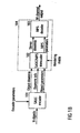
- Fig. 2 illustrates the operation of a spatial audio object (SAOC) encoder 101 taught by current invention.
- the N audio objects are fed both into a downmixer 201 and an audio object parameter extractor 202.
- the downmixer 201 mixes the objects into an object downmix consisting of K > 1 audio channels, according to the encoder parameters and also outputs downmix information.
- This information includes a description of the applied downmix weight matrix D and, optionally, if the subsequent audio object parameter extractor operates in prediction mode, parameters describing the power and correlation of the object downmix.
- the audio object parameter extractor 202 extracts object parameters according to the encoder parameters.
- the encoder control determines on a time and frequency varying basis which one of two encoder modes is applied, the energy based or the prediction based mode. In the energy based mode, the encoder parameters further contains information on a grouping of the N audio objects into P stereo objects and N -2 P mono objects. Each mode will be further described by Figures 3 and 4 .
- Fig. 3 illustrates an audio object parameter extractor 202 operating in energy based mode.
- a grouping 301 into P stereo objects and N- 2 P mono objects is performed according to grouping information contained in the encoder parameters. For each considered time frequency interval the following operations are then performed.
- Two object powers and one normalized correlation are extracted for each of the P stereo objects by the stereo parameter extractor 302.
- One power parameter is extracted for each of the N -2 P mono objects by the mono parameter extractor 303.
- the total set of N power parameters and P normalized correlation parameters is then encoded in 304 together with the grouping data to form the object parameters.
- the encoding can contain a normalization step with respect to the largest object power or with respect to the sum of extracted object powers.
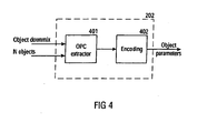
- Fig. 4 illustrates an audio object parameter extractor 202 operating in prediction based mode. For each considered time frequency interval the following operations are performed. For each of the N objects, a linear combination of the K object downmix channels is derived which matches the given object in a least squares sense. The K weights of this linear combination are called Object Prediction Coefficients (OPC) and they are computed by the OPC extractor 401 . The total set of N ⁇ K OPC's are encoded in 402 to form the object parameters. The encoding can incorporate a reduction of total number of OPC's based on linear interdependencies. As taught by the present invention, this total number can be reduced to max ⁇ K ⁇ ( N-K ),0 ⁇ if the downmix weight matrix D has full rank.
- OPC Object Prediction Coefficients
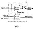
- Fig. 5 illustrates the structure of an SAOC to MPEG Surround transcoder 102 as taught by the current invention.
- the downmix side information and the object parameters are combined with the rendering matrix by the parameter calculator 502 to form MPEG Surround parameters of type CLD, CPC, and ICC, and a downmix converter matrix G of size 2 ⁇ K .
- the downmix converter 501 converts the object downmix into a stereo downmix by applying a matrix operation according to the G matrices.
- this matrix is the identity matrix and the object downmix is passed unaltered through as stereo downmix.
- This mode is illustrated in the drawing with the selector switch 503 in position A, whereas the normal operation mode has the switch in position B.
- An additional advantage of the transcoder is its usability as a stand alone application where the MPEG Surround parameters are ignored and the output of the downmix converter is used directly as a stereo rendering.
- Fig. 6 illustrates different operation modes of a downmix converter 501 as taught by the present invention.
- this bitstream is first decoded by the audio decoder 601 into K time domain audio signals. These signals are then all transformed to the frequency domain by an MPEG Surround hybrid QMF filter bank in the T/F unit 602.
- the time and frequency varying matrix operation defined by the converter matrix data is performed on the resulting hybrid QMF domain signals by the matrixing unit 603 which outputs a stereo signal in the hybrid QMF domain.
- the hybrid synthesis unit 604 converts the stereo hybrid QMF domain signal into a stereo QMF domain signal.
- the hybrid QMF domain is defined in order to obtain better frequency resolution towards lower frequencies by means of a subsequent filtering of the QMF subbands.
- this subsequent filtering is defined by banks of Nyquist filters
- the conversion from the hybrid to the standard QMF domain consists of simply summing groups of hybrid subband signals, see [ E. Schuijers, J. Breebart, and H. Purnhagen "Low complexity parametric stereo coding" Proc 116th AES convention Berlin ,Germany 2004, Preprint 6073 ].
- This signal constitutes the first possible output format of the downmix converter as defined by the selector switch 607 in position A.
- Such a QMF domain signal can be fed directly into the corresponding QMF domain interface of an MPEG Surround decoder, and this is the most advantageous operation mode in terms of delay, complexity and quality.
- the next possibility is obtained by performing a QMF filter bank synthesis 605 in order to obtain a stereo time domain signal. With the selector switch 607 in position B the converter outputs a digital audio stereo signal that also can be fed into the time domain interface of a subsequent MPEG Surround decoder, or rendered directly in a stereo playback device.
- the third possibility with the selector switch 607 in position C is obtained by encoding the time domain stereo signal with a stereo audio encoder 606.
- the output format of the downmix converter is then a stereo audio bitstream which is compatible with a core decoder contained in the MPEG decoder.
- This third mode of operation is suitable for the case where the SAOC to MPEG Surround transcoder is separated by the MPEG decoder by a connection that imposes restrictions on bitrate, or in the case where the user desires to store a particular object rendering for future playback.
- Fig 7 illustrates the structure of an MPEG Surround decoder for a stereo downmix.
- the stereo downmix is converted to three intermediate channels by the Two-To-Three (TTT) box.
- TTT Two-To-Three
- OTT One-To-Two
- Fig. 8 illustrates a practical use case including an SAOC encoder.
- An audio mixer 802 outputs a stereo signal (L and R) which typically is composed by combining mixer input signals (here input channels 1-6) and optionally additional inputs from effect returns such as reverb etc.
- the mixer also outputs an individual channel (here channel 5) from the mixer. This could be done e.g. by means of commonly used mixer functionalities such as "direct outputs" or "auxiliary send” in order to output an individual channel post any insert processes (such as dynamic processing and EQ).
- the stereo signal (L and R) and the individual channel output (obj5) are input to the SAOC encoder 801 , which is nothing but a special case of the SAOC encoder 101 in Fig. 1 .
- a signal block of L samples represents the signal in a time and frequency interval which is a part of the perceptually motivated tiling of the time-frequency plane which is applied for the description of signal properties.
- the task of the SAOC decoder is to generate an approximation in the perceptual sense of the target rendering Y of the original audio objects, given the rendering matrix A , the downmix X the downmix matrix D, and object parameters.
- the object parameters in the energy mode taught by the present invention carry information about the covariance of the original objects.
- this covariance is given in un-normalized form by the matrix product SS * where the star denotes the complex conjugate transpose matrix operation.
- energy mode object parameters furnish a positive semi-definite N ⁇ N matrix E such that, possibly up to a scale factor, SS * ⁇ E .
- the transcoder has to output a stereo downmix ( l 0 , r 0 ) and parameters for the TTT and OTT boxes.
- K 2
- K 2
- the object parameters can be in both energy or prediction mode, but the transcoder should preferably operate in prediction mode. If the downmix audio coder is not a waveform coder the in the considered frequency interval, the object encoder and the and the transcoder should both operate in energy mode.
- the fourth combination is of less relevance so the subsequent description will address the first three combinations only.
- the data available to the transcoder is described by the triplet of matrices (D, E, A).
- the MPEG Surround OTT parameters are obtained by performing energy and correlation estimates on a virtual rendering derived from the transmitted parameters and the 6 ⁇ N rendering matrix A.
- the MPEG surround decoder will be instructed to use some decorrelation between right front and right surround but no decorrelation between left front and left surround.
- the matrix C 3 contains the best weights for obtaining an approximation to the desired object rendering to the combined channels ( l, r, qc ) from the object downmix.
- This general type of matrix operation cannot be implemented by the MPEG surround decoder, which is tied to a limited space of TTT matrices through the use of only two parameters.
- the object of the inventive downmix converter is to pre-process the object downmix such that the combined effect of the pre-processing and the MPEG Surround TTT matrix is identical to the desired upmix described by C 3 .
- the available data is represented by the matrix triplet (D,C,A) where C is the N ⁇ 2 matrix holding the N pairs of OPC's. Due to the relative nature of prediction coefficients, it will further be necessary for the estimation of energy based MPEG Surround parameters to have access to an approximation to the 2 ⁇ 2 covariance matrix of the object downmix, XX * ⁇ Z .
- This information is preferably transmitted from the object encoder as part of the downmix side information, but it could also be estimated at the transcoder from measurements performed on the received downmix, or indirectly derived from (D, C) by approximate object model considerations.
- OPC's arises in combination with MPEG Surround TTT parameters in prediction mode.
- the resulting matrix G is fed to the downmix converter and the TTT parameters ( ⁇ , ⁇ ) are transmitted to the MPEG Surround decoder.
- the object to stereo downmix converter 501 outputs an approximation to a stereo downmix of the 5.1 channel rendering of the audio objects.
- this downmix is interesting in its own right and a direct manipulation of the stereo rendering A 2 is attractive.
- the design of the downmix converter matrix is based on GDS ⁇ A 2 ⁇ S .
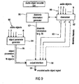
- Fig. 9 illustrates a preferred embodiment of an audio object coder in accordance with one aspect of the present invention.
- the audio object encoder 101 has already been generally described in connection with the preceding figures.
- the audio object coder for generating the encoded object signal uses the plurality of audio objects 90 which have been indicated in Fig. 9 as entering a downmixer 92 and an object parameter generator 94.
- the audio object encoder 101 includes the downmix information generator 96 for generating downmix information 97 indicating a distribution of the plurality of audio objects into at least two downmix channels indicated at 93 as leaving the downmixer 92.
- the object parameter generator is for generating object parameters 95 for the audio objects, wherein the object parameters are calculated such that the reconstruction of the audio object is possible using the object parameters and at least two downmix channels 93. Importantly, however, this reconstruction does not take place on the encoder side, but takes place on the decoder side. Nevertheless, the encoder-side object parameter generator calculates the object parameters for the objects 95 so that this full reconstruction can be performed on the decoder side.
- the audio object encoder 101 includes an output interface 98 for generating the encoded audio object signal 99 using the downmix information 97 and the object parameters 95.
- the downmix channels 93 can also be used and encoded into the encoded audio object signal.
- the output interface 98 generates an encoded audio object signal 99 which does not include the downmix channels. This situation may arise when any downmix channels to be used on the decoder side are already at the decoder side, so that the downmix information and the object parameters for the audio objects are transmitted separately from the downmix channels.
- Such a situation is useful when the object downmix channels 93 can be purchased separately from the object parameters and the downmix information for a smaller amount of money, and the object parameters and the downmix information can be purchased for an additional amount of money in order to provide the user on the decoder side with an added value.
- the object parameters and the downmix information enable the user to form a flexible rendering of the audio objects at any intended audio reproduction setup, such as a stereo system, a multi-channel system or even a wave field synthesis system. While wave field synthesis systems are not yet very popular, multi-channel systems such as 5.1 systems or 7.1 systems are becoming increasingly popular on the consumer market.
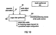
- Fig. 10 illustrates an audio synthesizer for generating output data.
- the audio synthesizer includes an output data synthesizer 100.
- the output data synthesizer receives, as an input, the downmix information 97 and audio object parameters 95 and, probably, intended audio source data such as a positioning of the audio sources or a user-specified volume of a specific source, which the source should have been when rendered as indicated at 101.
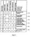
- the output data synthesizer 100 is for generating output data usable for creating a plurality of output channels of a predefined audio output configuration representing a plurality of audio objects. Particularly, the output data synthesizer 100 is operative to use the downmix information 97, and the audio object parameters 95. As discussed in connection with Fig. 11 later on, the output data can be data of a large variety of different useful applications, which include the specific rendering of output channels or which include just a reconstruction of the source signals or which include a transcoding of parameters into spatial rendering parameters for a spatial upmixer configuration without any specific rendering of output channels, but e.g. for storing or transmitting such spatial parameters.
- Fig. 14 The general application scenario of the present invention is summarized in Fig. 14 .
- an encoder side 140 which includes the audio object encoder 101 which receives, as an input, N audio objects.
- the output of the preferred audio object encoder comprises, in addition to the downmix information and the object parameters which are not shown in Fig. 14 , the K downmix channels.
- the number of downmix channels in accordance with the present invention is greater than or equal to two.
- the downmix channels are transmitted to a decoder side 142, which includes a spatial upmixer 143.
- the spatial upmixer 143 may include the inventive audio synthesizer, when the audio synthesizer is operated in a transcoder mode.
- the audio synthesizer 101 as illustrated in Fig. 10 works in a spatial upmixer mode, then the spatial upmixer 143 and the audio synthesizer are the same device in this embodiment.
- the spatial upmixer generates M output channels to be played via M speakers. These speakers are positioned at predefined spatial locations and together represent the predefined audio output configuration.
- An output channel of the predefined audio output configuration may be seen as a digital or analog speaker signal to be sent from an output of the spatial upmixer 143 to the input of a loudspeaker at a predefined position among the plurality of predefined positions of the predefined audio output configuration.
- the number of M output channels can be equal to two when stereo rendering is performed.
- the number of M output channels is larger than two.
- M is larger than K and may even be much larger than K, such as double the size or even more.
- Fig. 14 furthermore includes several matrix notations in order to illustrate the functionality of the inventive encoder side and the inventive decoder side.
- blocks of sampling values are processed. Therefore, as is indicated in equation (2), an audio object is represented as a line of L sampling values.
- the matrix S has N lines corresponding to the number of objects and L columns corresponding to the number of samples.
- the matrix E is calculated as indicated in equation (5) and has N columns and N lines.
- the matrix E includes the object parameters when the object parameters are given in the energy mode.
- the matrix E has, as indicated before in connection with equation (6) only main diagonal elements, wherein a main diagonal element gives the energy of an audio object. All off-diagonal elements represent, as indicated before, a correlation of two audio objects, which is specifically useful when some objects are two channels of the stereo signal.
- equation (2) is a time domain signal. Then a single energy value for the whole band of audio objects is generated.
- the audio objects are processed by a time/frequency converter which includes, for example, a type of a transform or a filter bank algorithm.
- equation (2) is valid for each subband so that one obtains a matrix E for each subband and, of course, each time frame.
- the downmix channel matrix X has K lines and L columns and is calculated as indicated in equation (3).
- the M output channels are calculated using the N objects by applying the so-called rendering matrix A to the N objects.
- the N objects can be regenerated on the decoder side using the downmix and the object parameters and the rendering can be applied to the reconstructed object signals directly.
- the downmix can be directly transformed to the output channels without an explicit calculation of the source signals.
- the rendering matrix A indicates the positioning of the individual sources with respect to the predefined audio output configuration. If one had six objects and six output channels, then one could place each object at each output channel and the rendering matrix would reflect this scheme. If, however, one would like to place all objects between two output speaker locations, then the rendering matrix A would look different and would reflect this different situation.
- the rendering matrix or, more generally stated, the intended positioning of the objects and also an intended relative volume of the audio sources can in general be calculated by an encoder and transmitted to the decoder as a so-called scene description.
- this scene description can be generated by the user herself/himself for generating the user-specific upmix for the user-specific audio output configuration.
- a transmission of the scene description is, therefore, not necessarily required, but the scene description can also be generated by the user in order to fulfill the wishes of the user.
- the user might, for example, like to place certain audio objects at places which are different from the places where these objects were when generating these objects.
- the audio objects are designed by themselves and do not have any "original" location with respect to the other objects. In this situation, the relative location of the audio sources is generated by the user at the first time.
- a downmixer 92 is illustrated.
- the downmixer is for downmixing the plurality of audio objects into the plurality of downmix channels, wherein the number of audio objects is larger than the number of downmix channels, and wherein the downmixer is coupled to the downmix information generator so that the distribution of the plurality of audio objects into the plurality of downmix channels is conducted as indicated in the downmix information.
- the downmix information generated by the downmix information generator 96 in Fig. 9 can be automatically created or manually adjusted. It is preferred to provide the downmix information with a resolution smaller than the resolution of the object parameters.
- the downmix information represents a downmix matrix having K lines and N columns.
- the value in a line of the downmix matrix has a certain value when the audio object corresponding to this value in the downmix matrix is in the downmix channel represented by the row of the downmix matrix.
- the values of more than one row of the downmix matrix have a certain value.
- Other values, however, are possible as well.
- audio objects can be input into one or more downmix channels with varying levels, and these levels can be indicated by weights in the downmix matrix which are different from one and which do not add up to 1.0 for a certain audio object.
- the encoded audio object signal may be for example a time-multiplex signal in a certain format.
- the encoded audio object signal can be any signal which allows the separation of the object parameters 95, the downmix information 97 and the downmix channels 93 on a decoder side.
- the output interface 98 can include encoders for the object parameters, the downmix information or the downmix channels. Encoders for the object parameters and the downmix information may be differential encoders and/or entropy encoders, and encoders for the downmix channels can be mono or stereo audio encoders such as MP3 encoders or AAC encoders. All these encoding operations result in a further data compression in order to further decrease the data rate required for the encoded audio object signal 99.
- the downmixer 92 is operative to include the stereo representation of background music into the at least two downmix channels and furthermore introduces the voice track into the at least two downmix channels in a predefined ratio.
- a first channel of the background music is within the first downmix channel and the second channel of the background music is within the second downmix channel. This results in an optimum replay of the stereo background music on a stereo rendering device. The user can, however, still modify the position of the voice track between the left stereo speaker and the right stereo speaker.
- the first and the second background music channels can be included in one downmix channel and the voice track can be included in the other downmix channel.
- a downmixer 92 is adapted to perform a sample by sample addition in the time domain. This addition uses samples from audio objects to be downmixed into a single downmix channel. When an audio object is to be introduced into a downmix channel with a certain percentage, a pre-weighting is to take place before the sample-wise summing process. Alternatively, the summing can also take place in the frequency domain, or a subband domain, i.e., in a domain subsequent to the time/frequency conversion. Thus, one could even perform the downmix in the filter bank domain when the time/frequency conversion is a filter bank or in the transform domain when the time/frequency conversion is a type of FFT, MDCT or any other transform.
- the object parameter generator 94 generates energy parameters and, additionally, correlation parameters between two objects when two audio objects together represent the stereo signal as becomes clear by the subsequent equation (6).
- the object parameters are prediction mode parameters.
- Fig. 15 illustrates algorithm steps or means of a calculating device for calculating these audio object prediction parameters. As has been discussed in connection with equations (7) to (12), some statistical information on the downmix channels in the matrix X and the audio objects in the matrix S has to be calculated. Particularly, block 150 illustrates the first step of calculating the real part of S ⁇ X* and the real part of X ⁇ X*.
- step 150 can be calculated using available data in the audio object encoder 101.
- the prediction matrix C is calculated as illustrated in step 152.
- the equation system is solved as known in the art so that all values of the prediction matrix C which has N lines and K columns are obtained.
- the weighting factors c n,i as given in equation (8) are calculated such that the weighted linear addition of all downmix channels reconstructs a corresponding audio object as well as possible. This prediction matrix results in a better reconstruction of audio objects when the number of downmix channels increases.
- Fig. 7 illustrates several kinds of output data usable for creating a plurality of output channels of a predefined audio output configuration.
- Line 111 illustrates a situation in which the output data of the output data synthesizer 100 are reconstructed audio sources.
- the input data required by the output data synthesizer 100 for rendering the reconstructed audio sources include downmix information, the downmix channels and the audio object parameters.
- an output configuration and an intended positioning of the audio sources themselves in the spatial audio output configuration are not necessarily required.
- the output data synthesizer 100 would output reconstructed audio sources.
- the output data synthesizer 100 works as defined by equation (7).
- the output data synthesizer uses an inverse of the downmix matrix and the energy matrix for reconstructing the source signals.
- the output data synthesizer 100 operates as a transcoder as illustrated for example in block 102 in Fig. 1b .
- the output synthesizer is a type of a transcoder for generating spatial mixer parameters
- the downmix information, the audio object parameters, the output configuration and the intended positioning of the sources are required.
- the output configuration and the intended positioning are provided via the rendering matrix A.
- the downmix channels are not required for generating the spatial mixer parameters as will be discussed in more detail in connection with Fig. 12 .
- the spatial mixer parameters generated by the output data synthesizer 100 can then be used by a straight-forward spatial mixer such as an MPEG-surround mixer for upmixing the downmix channels.
- This embodiment does not necessarily need to modify the object downmix channels, but may provide a simple conversion matrix only having diagonal elements as discussed in equation (13).
- the output data synthesizer 100 would, therefore, output spatial mixer parameters and, preferably, the conversion matrix G as indicated in equation (13), which includes gains that can be used as arbitrary downmix gain parameters (ADG) of the MPEG-surround decoder.
- ADG arbitrary downmix gain parameters
- the output data include spatial mixer parameters at a conversion matrix such as the conversion matrix illustrated in connection with equation (25).
- the output data synthesizer 100 does not necessarily have to perform the actual downmix conversion to convert the object downmix into a stereo downmix.
- a different mode of operation indicated by mode number 4 in line 114 in Fig. 11 illustrates the output data synthesizer 100 of Fig. 10 .
- the transcoder is operated as indicated by 102 in Fig. 1b and outputs not only spatial mixer parameters but additionally outputs a converted downmix. However, it is not necessary anymore to output the conversion matrix G in addition to the converted downmix. Outputting the converted downmix and the spatial mixer parameters is sufficient as indicated by Fig. 1b .
- Mode number 5 indicates another usage of the output data synthesizer 100 illustrated in Fig. 10 .
- the output data generated by the output data synthesizer do not include any spatial mixer parameters but only include a conversion matrix G as indicated by equation (35) for example or actually includes the output of the stereo signals themselves as indicated at 115.
- a stereo rendering is of interest and any spatial mixer parameters are not required.
- all available input information as indicated in Fig. 11 is required.
- Another output data synthesizer mode is indicated by mode number 6 at line 116.
- the output data synthesizer 100 generates a multi-channel output, and the output data synthesizer 100 would be similar to element 104 in Fig. 1b .
- the output data synthesizer 100 requires all available input information and outputs a multi-channel output signal having more than two output channels to be rendered by a corresponding number of speakers to be positioned at intended speaker positions in accordance with the predefined audio output configuration.
- Such a multi-channel output is a 5.1 output, a 7.1 output or only a 3.0 output having a left speaker, a center speaker and a right speaker.
- Fig. 11 illustrates one example for calculating several parameters from the Fig. 7 parameterization concept known from the MPEG-surround decoder.
- Fig. 7 illustrates an MPEG-surround decoder-side parameterization starting from the stereo downmix 70 having a left downmix channel l 0 and a right downmix channel r 0 .
- both downmix channels are input into a so-called Two-To-Three box 71.
- the Two-To-Three box is controlled by several input parameters 72.
- Box 71 generates three output channels 73a, 73b, 73c. Each output channel is input into a One-To-Two box.
- channel 73a is input into box 74a
- channel 73b is input into box 74b
- channel 73c is input into box 74c.
- Each box outputs two output channels.
- Box 74a outputs a left front channel l f and a left surround channel l s .
- box 74b outputs a right front channel r f and a right surround channel r s .
- box 74c outputs a center channel c and a low-frequency enhancement channel Ife.
- the whole upmix from the downmix channels 70 to the output channels is performed using a matrix operation, and the tree structure as shown in Fig. 7 is not necessarily implemented step by step but can be implemented via a single or several matrix operations.
- the intermediate signals indicated by 73a, 73b and 73c are not explicitly calculated by a certain embodiment, but are illustrated in Fig. 7 only for illustration purposes.
- boxes 74a, 74b receive some residual signals res 1 OTT , res 2 OTT which can be used for introducing a certain randomness into the output signals.
- box 71 is controlled either by prediction parameters CPC or energy parameters CLD TTT .
- prediction parameters CPC For the upmix from two channels to three channels, at least two prediction parameters CPC1, CPC2 or at least two energy parameters CLD 1 TTT and CLD 2 TTT are required.
- the correlation measure ICC TTT can be put into the box 71 which is, however, only an optional feature which is not used in one embodiment of the invention.
- Figs. 12 and 13 illustrate the necessary steps and/or means for calculating all parameters CPC/CLD TTT , CLD0, CLD1, ICC1, CLD2, ICC2 from the object parameters 95 of Fig. 9 , the downmix information 97 of Fig. 9 and the intended positioning of the audio sources, e.g. the scene description 101 as illustrated in Fig. 10 .
- These parameters are for the predefined audio output format of a 5.1 surround system.
- a rendering matrix A is provided.
- the rendering matrix indicates where the source of the plurality of sources is to be placed in the context of the predefined output configuration.
- Step 121 illustrates the derivation of the partial downmix matrix D 36 as indicated in equation (20). This matrix reflects the situation of a downmix from six output channels to three channels and has a size of 3xN. When one intends to generate more output channels than the 5.1 configuration, such as an 8-channel output configuration (7.1), then the matrix determined in block 121 would be a D 38 matrix.
- a reduced rendering matrix A 3 is generated by multiplying matrix D 36 and the full rendering matrix as defined in step 120.
- the downmix matrix D is introduced. This downmix matrix D can be retrieved from the encoded audio object signal when the matrix is fully included in this signal. Alternatively, the downmix matrix could be parameterized e.g. for the specific downmix information example and the downmix matrix G.
- the object energy matrix is provided in step 124.
- This object energy matrix is reflected by the object parameters for the N objects and can be extracted from the imported audio objects or reconstructed using a certain reconstruction rule.
- This reconstruction rule may include an entropy decoding etc.
- step 125 the "reduced" prediction matrix C 3 is defined.
- the values of this matrix can be calculated by solving the system of linear equations as indicated in step 125. Specifically, the elements of matrix C 3 can be calculated by multiplying the equation on both sides by an inverse of (DED*).
- step 126 the conversion matrix G is calculated.
- the conversion matrix G has a size of KxK and is generated as defined by equation (25).
- the specific matrix D TTT is to be provided as indicated by step 127.
- An example for this matrix is given in equation (24) and the definition can be derived from the corresponding equation for C TTT as defined in equation (22). Equation (22), therefore, defines what is to be done in step 128.
- Step 129 defines the equations for calculating matrix C TTT .
- the parameters ⁇ , ⁇ and ⁇ which are the CPC parameters, can be output.
- ⁇ is set to 1 so that the only remaining CPC parameters input into block 71 are ⁇ and ⁇ .
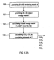
- the rendering matrix A is provided.
- the size of the rendering matrix A is N lines for the number of audio objects and M columns for the number of output channels.
- This rendering matrix includes the information from the scene vector, when a scene vector is used.
- the rendering matrix includes the information of placing an audio source in a certain position in an output setup.
- the rendering matrix is generated on the decoder side without any information from the encoder side. This allows a user to place the audio objects wherever the user likes without paying attention to a spatial relation of the audio objects in the encoder setup.
- the relative or absolute location of audio sources can be encoded on the encoder side and transmitted to the decoder as a kind of a scene vector. Then, on the decoder side, this information on locations of audio sources which is preferably independent of an intended audio rendering setup is processed to result in a rendering matrix which reflects the locations of the audio sources customized to the specific audio output configuration.
- step 131 the object energy matrix E which has already been discussed in connection with step 124 of Fig. 12 is provided.
- This matrix has the size ofNxN and includes the audio object parameters.
- such an object energy matrix is provided for each subband and each block of time-domain samples or subband-domain samples.
- the output energy matrix F is calculated.
- F is the covariance matrix of the output channels. Since the output channels are, however, still unknown, the output energy matrix F is calculated using the rendering matrix and the energy matrix.
- These matrices are provided in steps 130 and 131 and are readily available on the decoder side. Then, the specific equations (15), (16), (17), (18) and (19) are applied to calculate the channel level difference parameters CLD 0 , CLD 1 , CLD 2 and the inter-channel coherence parameters ICC 1 and ICC 2 so that the parameters for the boxes 74a, 74b, 74c are available. Importantly, the spatial parameters are calculated by combining the specific elements of the output energy matrix F.
- step 133 all parameters for a spatial upmixer, such as the spatial upmixer as schematically illustrated in Fig. 7 , are available.
- the object parameters were given as energy parameters.
- the object parameters are given as prediction parameters, i.e. as an object prediction matrix C as indicated by item 124a in Fig. 12
- the calculation of the reduced prediction matrix C 3 is just a matrix multiplication as illustrated in block 125a and discussed in connection with equation (32).
- the matrix A 3 as used in block 125a is the same matrix A 3 as mentioned in block 122 of Fig. 12 .
- the object prediction matrix C is generated by an audio object encoder and transmitted to the decoder, then some additional calculations are required for generating the parameters for the boxes 74a, 74b, 74c. These additional steps are indicated in Fig. 13b .
- the object prediction matrix C is provided as indicated by 124a in Fig. 13b , which is the same as discussed in connection with block 124a of Fig. 12 .
- the covariance matrix of the object downmix Z is calculated using the transmitted downmix or is generated and transmitted as additional side information.
- the decoder does not necessarily have to perform any energy calculations which inherently introduce some delayed processing and increase the processing load on the decoder side.
- step 134 the object energy matrix E can be calculated as indicated by step 135 by using the prediction matrix C and the downmix covariance or "downmix energy" matrix Z.
- step 135 all steps discussed in connection with Fig. 13a can be performed, such as steps 132, 133, to generate all parameters for blocks 74a, 74b, 74c of Fig. 7 .
- Fig. 16 illustrates a further embodiment, in which only a stereo rendering is required.
- the stereo rendering is the output as provided by mode number 5 or line 115 of Fig. 11 .
- the output data synthesizer 100 of Fig. 10 is not interested in any spatial upmix parameters but is mainly interested in a specific conversion matrix G for converting the object downmix into a useful and, of course, readily influencable and readily controllable stereo downmix.
- an M-to-2 partial downmix matrix is calculated.
- the partial downmix matrix would be a downmix matrix from six to two channels, but other downmix matrices are available as well.
- the calculation of this partial downmix matrix can be, for example, derived from the partial downmix matrix D 36 as generated in step 121 and matrix D TTT as used in step 127 of Fig. 12 .
- a stereo rendering matrix A 2 is generated using the result of step 160 and the "big" rendering matrix A is illustrated in step 161.
- the rendering matrix A is the same matrix as has been discussed in connection with block 120 in Fig. 12 .
- the stereo rendering matrix may be parameterized by placement parameters ⁇ and ⁇ .
- ⁇ is set to 1 and ⁇ is set to 1 as well, then the equation (33) is obtained, which allows a variation of the voice volume in the example described in connection with equation (33).
- other parameters such as ⁇ and ⁇ are used, then the placement of the sources can be varied as well.
- the conversion matrix G is calculated by using equation (33).
- the matrix (DED*) can be calculated, inverted and the inverted matrix can be multiplied to the right-hand side of the equation in block 163.
- the conversion matrix G is there, and the object downmix X can be converted by multiplying the conversion matrix and the object downmix as indicated in block 164.
- the converted downmix X' can be stereo-rendered using two stereo speakers.
- certain values for ⁇ , ⁇ and ⁇ can be set for calculating the conversion matrix G.
- the conversion matrix G can be calculated using all these three parameters as variables so that the parameters can be set subsequent to step 163 as required by the user.
- Preferred embodiments solve the problem of transmitting a number of individual audio objects (using a multi-channel downmix and additional control data describing the objects) and rendering the objects to a given reproduction system (loudspeaker configuration).
- a technique on how to modify the object related control data into control data that is compatible to the reproduction system is introduced. It further proposes suitable encoding methods based on the MPEG Surround coding scheme.
- the inventive methods and signals can be implemented in hardware or in software.
- the implementation can be performed using a digital storage medium, in particular a disk or a CD having electronically readable control signals stored thereon, which can cooperate with a programmable computer system such that the inventive methods are performed.
- the present invention is, therefore, a computer program product with a program code stored on a machine-readable carrier, the program code being configured for performing at least one of the inventive methods, when the computer program products runs on a computer.
- the inventive methods are, therefore, a computer program having a program code for performing the inventive methods, when the computer program runs on a computer.
- an audio object coder for generating an encoded audio object signal using a plurality of audio objects comprises a downmix information generator for generating downmix information indicating a distribution of the plurality of audio objects into at least two downmix channels; an object parameter generator for generating object parameters for the audio objects; and an output interface for generating the encoded audio object signal using the downmix information and the object parameters.
- the output interface may operate to generate the encoded audio signal by additionally using the plurality of downmix channels.
- the parameter generator may be operative to generate the object parameters with a first time and frequency resolution, and wherein the downmix information generator is operative to generate the downmix information with a second time and frequency resolution, the second time and frequency resolution being smaller than the first time and frequency resolution.
- the downmix information generator may be operative to generate the downmix information such that the downmix information is equal for the whole frequency band of the audio objects.
- the information on a portion may be a factor smaller than 1 and greater than 0.
- the downmixer may be operative to include the stereo representation of background music into the at least two downmix channels, and to introduce a voice track into the at least two downmix channels in a predefined ratio.
- the downmixer may be operative to perform a sample-wise addition of signals to be input into a downmix channel as indicated by the downmix information.
- the output interface may be operative to perform a data compression of the downmix information and the object parameters before generating the encoded audio object signal.
- the plurality of audio objects may include a stereo object represented by two audio objects having a certain non-zero correlation, and in which the downmix information generator generates a grouping information indicating the two audio objects forming the stereo object.
- the object parameter generator may be operative to generate object prediction parameters for the audio objects, the prediction parameters being calculated such that the weighted addition of the downmix channels for a source object controlled by the prediction parameters or the source object results in an approximation of the source object.
- the prediction parameters may be generated per frequency band, and wherein the audio objects cover a plurality of frequency bands.
- the number of audio object may be equal to N
- the number of downmix channels is equal to K
- the number of object prediction parameters calculated by the object parameter generator is equal to or smaller than N ⁇ K.
- the object parameter generator may be operative to calculate at most K ⁇ (N-K) object prediction parameters.
- the object parameter generator may include an upmixer for upmixing the plurality of downmix channels using different sets of test object prediction parameters; and in which the audio object coder furthermore comprises an iteration controller for finding the test object prediction parameters resulting in the smallest deviation between a source signal reconstructed by the upmixer and the corresponding original source signal among the different sets of test object prediction parameters.
- the output data synthesizer may be operative to determine the conversion matrix using the downmix information, wherein the conversion matrix is calculated so that at least portions of the downmix channels are swapped when an audio object included in a first downmix channel representing the first half of a stereo plane is to be played in the second half of the stereo plane.
- the audio synthesizer may comprise a channel renderer for rendering audio output channels for the predefined audio output configuration using the spatial parameters and the at least two downmix channels or the converted downmix channels.
- the output data synthesizer may be operative to output the output channels of the predefined audio output configuration additionally using the at least two downmix channels.
- the output data synthesizer may be operative to calculate actual downmix weights for the partial downmix matrix such that an energy of a weighted sum of two channels is equal to the energies of the channels within a limit factor.
- the output data synthesizer may be operative to calculate separate coefficients of the prediction matrix by solving a system of linear equations.
- the prediction parameters for the Two-To-Three upmix may be derived from a parameterization of the prediction matrix so that the prediction matrix is defined by using two parameters only, and in which the output data synthesizer is operative to preprocess the at least two downmix channels so that the effect of the preprocessing and the parameterized prediction matrix corresponds to a desired upmix matrix.
- the prediction parameters for the Two-To-Three upmix may be determined as ⁇ and ⁇ , wherein ⁇ is set to 1.
- the output data synthesizer may be operative to calculate the energy parameters by combining elements of the energy matrix.
- or a real value operator ⁇ (z) Re ⁇ z ⁇ , wherein CLD 0 is a first channel level difference energy parameter, wherein CLD 1 is a second channel level difference energy parameter, wherein CLD 2 is a third channel level difference energy parameter, wherein ICC 1 is a first inter-channel coherence energy parameter, and ICC 2 is a second inter-channel coherence energy parameter, and wherein f ij are elements of an energy matrix F at positions ij in this matrix.
- the first group of parameters may include energy parameters, and in which the output data synthesizer is operative to derive the energy parameters by combining elements of the energy matrix F.
- the output data synthesizer may be operative to calculate weight factors for weighting the downmix channels, the weight factors being used for controlling arbitrary downmix gain factors of the spatial decoder.
- the parameterized stereo rendering matrix A 2 may be determined as follows: ⁇ 1 - ⁇ ⁇ 1 - ⁇ ⁇ ⁇ wherein ⁇ , ⁇ , and ⁇ are real valued parameters to be set in accordance with position and volume of one or more source audio objects.
Claims (13)
- Synthétiseur audio (104) pour générer des données de sortie à l'aide d'un signal d'objet audio codé (95, 97), comprenant:un synthétiseur de données de sortie (100) destiné à générer les données de sortie utilisables pour rendre une pluralité de canaux de sortie d'une configuration de sortie audio prédéfinie représentant la pluralité d'objets audio, le synthétiseur de données de sortie étant opérationnel pour utiliser les informations de mélange vers le bas indiquant une répartition de la pluralité d'objets audio dans au moins deux canaux de mélange vers le bas, les informations de puissance et les informations de corrélation indiquant une caractéristique de puissance et une caractéristique de corrélation des au moins deux canaux de mélange vers le bas (93), et les paramètres d'objet audio pour les objets audio, où le synthétiseur de données de sortie (100) est opérationnel pour transcoder (502) les paramètres d'objet audio en paramètres spatiaux pour la configuration de sortie audio prédéfinie en plus à l'aide d'un positionnement prévu des objets audio (90) dans la configuration de sortie audio.
- Synthétiseur audio selon la revendication 1, dans lequel le synthétiseur de données de sortie (100) est opérationnel pour convertir une pluralité canaux de mélange vers le bas en mélange vers le bas stéréo pour la configuration de sortie audio prédéfinie à l'aide d'une matrice de conversion dérivée du positionnement prévu des objets audio
- Synthétiseur audio selon la revendication 1, dans lequel les paramètres spatiaux comportent le premier groupe de paramètres pour un mélange vers le haut Deux-à-Trois et un deuxième groupe de paramètres d'énergie pour un mélange vers le haut Trois-à-Six, et
dans lequel le synthétiseur de données de sortie (100) est opérationnel pour calculer les paramètres de prédiction pour la matrice de prédiction Deux-à-Trois à l'aide d'une matrice de rendu telle que déterminée par un positionnement prévu des objets audio (90), une matrice de mélange vers le bas partiel décrivant le mélange vers le bas des canaux de sortie à trois canaux générés par un processus de mélange vers le haut Deux-à-Trois hypothétique, et la matrice de mélange vers le bas. - Synthétiseur audio selon la revendication 3, dans lequel les paramètres d'objet sont des paramètres de prédiction d'objet, et dans lequel le synthétiseur de données de sortie (100) est opérationnel pour pré-calculer une matrice d'énergie sur base des paramètres de prédiction d'objet, des informations de mélange vers le bas et des informations d'énergie correspondant aux canaux de mélange vers le bas.
- Synthétiseur audio selon la revendication 1, dans lequel le synthétiseur de données de sortie (100) est opérationnel pour générer (165) deux canaux stéréo pour une configuration de sortie stéréo en calculant une matrice de rendu stéréo paramétrisée et une matrice de conversion dépendant de la matrice de rendu stéréo paramétrisée.
- Procédé de synthétisation audio pour générer des données de sortie à l'aide d'un signal d'objet audio codé (95, 97), comprenant:générer les données de sortie utilisables pour créer une pluralité de canaux de sortie d'une configuration de sortie audio prédéfinie représentant la pluralité d'objets audio (90), où sont utilisées les informations de mélange vers le bas indiquant une répartition de la pluralité d'objets audio dans au moins deux canaux de mélange vers le bas, les informations de puissance, les informations de corrélation indiquant une caractéristique de puissance et une caractéristique de corrélation des au moins deux canaux de mélange vers le bas (93), et les paramètres d'objet audio pour les objets audio, et où les paramètres d'objet audio sont transcodés (502) en paramètres spatiaux pour la configuration de sortie audio prédéfinie en plus à l'aide d'un positionnement prévu des objets audio (90) dans la configuration de sortie audio.
- Codeur d'objet audio (101) pour générer un signal d'objet audio codé à l'aide d'une pluralité d'objets audio (90), comprenant:un générateur d'informations de mélange vers le bas (96) destiné à générer des informations de mélange vers le bas (97) indiquant une répartition de la pluralité d'objets audio dans au moins deux canaux de mélange vers le bas, où le générateur d'informations de mélange vers le bas (96) est configuré pour générer (150) une information de puissance et une information de corrélation indiquant une caractéristique de puissance et une caractéristique de corrélation des au moins deux canaux de mélange vers le bas (93);un générateur de paramètres d'objet (94) destiné à générer des paramètres d'objet (95) pour les objets audio; etune interface de sortie (98) destinée à générer le signal d'objet audio codé (99), le signal d'objet codé comprenant les informations de mélange vers le bas, les informations de puissance, les informations de corrélation, et les paramètres d'objet.
- Codeur d'objet audio selon la revendication 7, comprenant par ailleurs:un mélangeur vers le bas (92) destiné à mélanger vers le bas la pluralité d'objets audio la pluralité de canaux de mélange vers le bas, où le nombre d'objets audio est supérieur au nombre de canaux de mélange vers le bas, et où le mélangeur vers le bas (92) est couplé au générateur d'informations de mélange vers le bas de sorte que la répartition de la pluralité d'objets audio dans la pluralité de canaux de mélange vers le bas soit réalisée tel qu'indiqué dans les informations de mélange vers le bas.
- Codeur d'objet audio selon la revendication 7, dans lequel le générateur d'informations de mélange vers le bas (96) est opérationnel pour calculer les informations de mélange vers le bas de sorte que les informations de mélange vers le bas indiquent l'objet audio qui est totalement ou partiellement inclus dans un ou plusieurs de la pluralité de canaux de mélange vers le bas, et lorsqu'un objet audio est inclus dans plus d'un canal de mélange vers le bas, une information sur une partie des objets audio inclus dans un canal de mélange vers le bas parmi les plus d'un canal de mélange vers le bas.
- Procédé de codage d'un objet audio (101) pour générer un signal d'objet audio codé à l'aide d'une pluralité d'objets audio, comprenant:générer les informations de mélange vers le bas (97) indiquant une répartition de la pluralité d'objets audio (90) dans au moins deux canaux de mélange vers le bas,générer (150) une information de puissance et une information de corrélation indiquant une caractéristique de puissance et une caractéristique de corrélation des au moins deux canaux de mélange vers le bas;générer les paramètres d'objet (94) pour les objets audio; etgénérer le signal d'objet audio codé (99), le signal d'objet audio codé comprenant l'information de puissance, l'information de corrélation, l'information de mélange vers le bas et les paramètres d'objet.
- Signal d'objet audio codé comportant une information de mélange vers le bas indiquant une répartition d'une pluralité d'objets audio en au moins deux canaux de mélange vers le bas, une information de puissance et une information de corrélation indiquant une caractéristique de puissance et une caractéristique de corrélation des au moins deux canaux de mélange vers le bas, et des paramètres d'objet, les paramètres d'objet étant tels que la reconstruction des objets audio soit possible à l'aide des paramètres d'objet et des au moins deux canaux de mélange vers le bas.
- Signal d'objet audio codé selon la revendication 11 mémorisé sur un support de mémoire lisible par ordinateur.
- Programme d'ordinateur pour réaliser, lorsqu'il est exécuté sur un ordinateur, un procédé selon l'un quelconque des procédés des revendications 6 ou 10.
Priority Applications (2)
| Application Number | Priority Date | Filing Date | Title |
|---|---|---|---|
| EP11153938.3A EP2372701B1 (fr) | 2006-10-16 | 2007-10-05 | Codage amélioré et représentation de paramètre de codage d'objet à mélange abaisseur multicanaux |
| PL09004406T PL2068307T3 (pl) | 2006-10-16 | 2007-10-05 | Udoskonalony sposób kodowania i odtwarzania parametrów w wielokanałowym kodowaniu obiektów poddanych procesowi downmiksu |
Applications Claiming Priority (2)
| Application Number | Priority Date | Filing Date | Title |
|---|---|---|---|
| US82964906P | 2006-10-16 | 2006-10-16 | |
| EP07818759A EP2054875B1 (fr) | 2006-10-16 | 2007-10-05 | Codage amélioré et représentation de paramètres d'un codage d'objet à mélange abaisseur multi-canal |
Related Parent Applications (2)
| Application Number | Title | Priority Date | Filing Date |
|---|---|---|---|
| EP07818759.8 Division | 2007-10-05 | ||
| EP07818759A Division EP2054875B1 (fr) | 2006-10-16 | 2007-10-05 | Codage amélioré et représentation de paramètres d'un codage d'objet à mélange abaisseur multi-canal |
Related Child Applications (1)
| Application Number | Title | Priority Date | Filing Date |
|---|---|---|---|
| EP11153938.3 Division-Into | 2011-02-10 |
Publications (2)
| Publication Number | Publication Date |
|---|---|
| EP2068307A1 EP2068307A1 (fr) | 2009-06-10 |
| EP2068307B1 true EP2068307B1 (fr) | 2011-12-07 |
Family
ID=38810466
Family Applications (3)
| Application Number | Title | Priority Date | Filing Date |
|---|---|---|---|
| EP09004406A Active EP2068307B1 (fr) | 2006-10-16 | 2007-10-05 | Codage amélioré et représentation de paramètre de codage d'objet à mélange abaisseur multicanaux |
| EP11153938.3A Active EP2372701B1 (fr) | 2006-10-16 | 2007-10-05 | Codage amélioré et représentation de paramètre de codage d'objet à mélange abaisseur multicanaux |
| EP07818759A Active EP2054875B1 (fr) | 2006-10-16 | 2007-10-05 | Codage amélioré et représentation de paramètres d'un codage d'objet à mélange abaisseur multi-canal |
Family Applications After (2)
| Application Number | Title | Priority Date | Filing Date |
|---|---|---|---|
| EP11153938.3A Active EP2372701B1 (fr) | 2006-10-16 | 2007-10-05 | Codage amélioré et représentation de paramètre de codage d'objet à mélange abaisseur multicanaux |
| EP07818759A Active EP2054875B1 (fr) | 2006-10-16 | 2007-10-05 | Codage amélioré et représentation de paramètres d'un codage d'objet à mélange abaisseur multi-canal |
Country Status (21)
| Country | Link |
|---|---|
| US (2) | US9565509B2 (fr) |
| EP (3) | EP2068307B1 (fr) |
| JP (3) | JP5270557B2 (fr) |
| KR (2) | KR101103987B1 (fr) |
| CN (3) | CN102892070B (fr) |
| AT (2) | ATE503245T1 (fr) |
| AU (2) | AU2007312598B2 (fr) |
| CA (3) | CA2874454C (fr) |
| DE (1) | DE602007013415D1 (fr) |
| ES (1) | ES2378734T3 (fr) |
| HK (3) | HK1133116A1 (fr) |
| MX (1) | MX2009003570A (fr) |
| MY (1) | MY145497A (fr) |
| NO (1) | NO340450B1 (fr) |
| PL (1) | PL2068307T3 (fr) |
| PT (1) | PT2372701E (fr) |
| RU (1) | RU2430430C2 (fr) |
| SG (1) | SG175632A1 (fr) |
| TW (1) | TWI347590B (fr) |
| UA (1) | UA94117C2 (fr) |
| WO (1) | WO2008046531A1 (fr) |
Families Citing this family (139)
| Publication number | Priority date | Publication date | Assignee | Title |
|---|---|---|---|---|
| CN101228575B (zh) * | 2005-06-03 | 2012-09-26 | 杜比实验室特许公司 | 利用侧向信息的声道重新配置 |
| KR20080093422A (ko) * | 2006-02-09 | 2008-10-21 | 엘지전자 주식회사 | 오브젝트 기반 오디오 신호의 부호화 및 복호화 방법과 그장치 |
| CN101617360B (zh) | 2006-09-29 | 2012-08-22 | 韩国电子通信研究院 | 用于编码和解码具有各种声道的多对象音频信号的设备和方法 |
| CN101529898B (zh) * | 2006-10-12 | 2014-09-17 | Lg电子株式会社 | 用于处理混合信号的装置及其方法 |
| ATE539434T1 (de) | 2006-10-16 | 2012-01-15 | Fraunhofer Ges Forschung | Vorrichtung und verfahren für mehrkanalparameterumwandlung |
| MX2009003570A (es) | 2006-10-16 | 2009-05-28 | Dolby Sweden Ab | Codificacion mejorada y representacion de parametros para codificacion de objetos de mezcla descendente de multicanal. |
| US8571875B2 (en) * | 2006-10-18 | 2013-10-29 | Samsung Electronics Co., Ltd. | Method, medium, and apparatus encoding and/or decoding multichannel audio signals |
| KR20090028723A (ko) * | 2006-11-24 | 2009-03-19 | 엘지전자 주식회사 | 오브젝트 기반 오디오 신호의 부호화 및 복호화 방법과 그 장치 |
| AU2007328614B2 (en) | 2006-12-07 | 2010-08-26 | Lg Electronics Inc. | A method and an apparatus for processing an audio signal |
| EP2097895A4 (fr) * | 2006-12-27 | 2013-11-13 | Korea Electronics Telecomm | Dispositif et procédé de codage et décodage de signal audio multi-objet avec différents canaux avec conversion de débit binaire d'information |
| JP5232795B2 (ja) * | 2007-02-14 | 2013-07-10 | エルジー エレクトロニクス インコーポレイティド | オブジェクトベースのオーディオ信号の符号化及び復号化方法並びにその装置 |
| WO2008102527A1 (fr) * | 2007-02-20 | 2008-08-28 | Panasonic Corporation | Dispositif de décodage multiplex, procédé de décodage multiplex, programme et circuit intégré à semi-conducteur |
| KR20080082917A (ko) * | 2007-03-09 | 2008-09-12 | 엘지전자 주식회사 | 오디오 신호 처리 방법 및 이의 장치 |
| EP2137726B1 (fr) * | 2007-03-09 | 2011-09-28 | LG Electronics Inc. | Procédé et appareil de traitement de signal audio |
| EP2130304A4 (fr) | 2007-03-16 | 2012-04-04 | Lg Electronics Inc | Procédé et dispositif de traitement de signal audio |
| JP5220840B2 (ja) * | 2007-03-30 | 2013-06-26 | エレクトロニクス アンド テレコミュニケーションズ リサーチ インスチチュート | マルチチャネルで構成されたマルチオブジェクトオーディオ信号のエンコード、並びにデコード装置および方法 |
| JP2010538571A (ja) | 2007-09-06 | 2010-12-09 | エルジー エレクトロニクス インコーポレイティド | オーディオ信号のデコーディング方法及び装置 |
| BRPI0816557B1 (pt) * | 2007-10-17 | 2020-02-18 | Fraunhofer-Gesellschaft Zur Foerderung Der Angewandten Forschung E.V. | Codificação de áudio usando upmix |
| US20110282674A1 (en) * | 2007-11-27 | 2011-11-17 | Nokia Corporation | Multichannel audio coding |
| US8600532B2 (en) * | 2007-12-09 | 2013-12-03 | Lg Electronics Inc. | Method and an apparatus for processing a signal |
| WO2009086174A1 (fr) | 2007-12-21 | 2009-07-09 | Srs Labs, Inc. | Système pour ajuster la sonie perçue de signaux audio |
| US8386267B2 (en) * | 2008-03-19 | 2013-02-26 | Panasonic Corporation | Stereo signal encoding device, stereo signal decoding device and methods for them |
| KR101461685B1 (ko) * | 2008-03-31 | 2014-11-19 | 한국전자통신연구원 | 다객체 오디오 신호의 부가정보 비트스트림 생성 방법 및 장치 |
| BR122020009727B1 (pt) * | 2008-05-23 | 2021-04-06 | Koninklijke Philips N.V. | Método |
| US8315396B2 (en) * | 2008-07-17 | 2012-11-20 | Fraunhofer-Gesellschaft Zur Foerderung Der Angewandten Forschung E.V. | Apparatus and method for generating audio output signals using object based metadata |
| RU2495503C2 (ru) * | 2008-07-29 | 2013-10-10 | Панасоник Корпорэйшн | Устройство кодирования звука, устройство декодирования звука, устройство кодирования и декодирования звука и система проведения телеконференций |
| KR101335975B1 (ko) | 2008-08-14 | 2013-12-04 | 돌비 레버러토리즈 라이쎈싱 코오포레이션 | 복수의 오디오 입력 신호를 리포맷팅하는 방법 |
| US8861739B2 (en) | 2008-11-10 | 2014-10-14 | Nokia Corporation | Apparatus and method for generating a multichannel signal |
| EP2194526A1 (fr) * | 2008-12-05 | 2010-06-09 | Lg Electronics Inc. | Procédé et appareil de traitement de signal audio |
| KR20100065121A (ko) * | 2008-12-05 | 2010-06-15 | 엘지전자 주식회사 | 오디오 신호 처리 방법 및 장치 |
| EP2395504B1 (fr) * | 2009-02-13 | 2013-09-18 | Huawei Technologies Co., Ltd. | Procede et dispositif de codage stereo |
| RU2520329C2 (ru) | 2009-03-17 | 2014-06-20 | Долби Интернешнл Аб | Усовершенствованное стереофоническое кодирование на основе комбинации адаптивно выбираемого левого/правого или среднего/побочного стереофонического кодирования и параметрического стереофонического кодирования |
| GB2470059A (en) * | 2009-05-08 | 2010-11-10 | Nokia Corp | Multi-channel audio processing using an inter-channel prediction model to form an inter-channel parameter |
| JP2011002574A (ja) * | 2009-06-17 | 2011-01-06 | Nippon Hoso Kyokai <Nhk> | 3次元音響符号化装置、3次元音響復号装置、符号化プログラム及び復号プログラム |
| US20100324915A1 (en) * | 2009-06-23 | 2010-12-23 | Electronic And Telecommunications Research Institute | Encoding and decoding apparatuses for high quality multi-channel audio codec |
| KR101283783B1 (ko) * | 2009-06-23 | 2013-07-08 | 한국전자통신연구원 | 고품질 다채널 오디오 부호화 및 복호화 장치 |
| US8538042B2 (en) * | 2009-08-11 | 2013-09-17 | Dts Llc | System for increasing perceived loudness of speakers |
| JP5345024B2 (ja) * | 2009-08-28 | 2013-11-20 | 日本放送協会 | 3次元音響符号化装置、3次元音響復号装置、符号化プログラム及び復号プログラム |
| JP5758902B2 (ja) * | 2009-10-16 | 2015-08-05 | フラウンホッファー−ゲゼルシャフト ツァ フェルダールング デァ アンゲヴァンテン フォアシュンク エー.ファオ | ダウンミックス信号表現と、ダウンミックス信号表現に関係するパラメトリックサイド情報に基づくアップミックス信号表現の提供に対して、平均値を用いて、1つ以上の調整されたパラメータを提供する装置、方法およびコンピュータプログラム |
| EP2704143B1 (fr) * | 2009-10-21 | 2015-01-07 | Panasonic Intellectual Property Corporation of America | Dispositif, procédé et programme informatique pour le traitement d'un signal audio |
| KR20110049068A (ko) * | 2009-11-04 | 2011-05-12 | 삼성전자주식회사 | 멀티 채널 오디오 신호의 부호화/복호화 장치 및 방법 |
| WO2011061174A1 (fr) * | 2009-11-20 | 2011-05-26 | Fraunhofer-Gesellschaft zur Förderung der angewandten Forschung e.V. | Appareil servant à fournir une représentation d'un signal de mixage élévateur sur la base de la représentation d'un signal de mixage réducteur, appareil servant à fournir un flux binaire représentant un signal audio multicanal, procédés, programmes informatiques et flux binaire représentant un signal audio multicanal utilisant un paramètre de combinaison linéaire |
| WO2011071928A2 (fr) * | 2009-12-07 | 2011-06-16 | Pixel Instruments Corporation | Détecteur de dialogue et correction |
| US20120277894A1 (en) * | 2009-12-11 | 2012-11-01 | Nsonix, Inc | Audio authoring apparatus and audio playback apparatus for an object-based audio service, and audio authoring method and audio playback method using same |
| EP2522016A4 (fr) | 2010-01-06 | 2015-04-22 | Lg Electronics Inc | Appareil pour traiter un signal audio et procédé associé |
| EP2539889B1 (fr) * | 2010-02-24 | 2016-08-24 | Fraunhofer-Gesellschaft zur Förderung der Angewandten Forschung e.V. | Appareil de génération de signal de mixage réducteur amélioré, procédé de génération de signal de mixage réducteur amélioré et programme informatique |
| US10158958B2 (en) | 2010-03-23 | 2018-12-18 | Dolby Laboratories Licensing Corporation | Techniques for localized perceptual audio |
| CN113490132B (zh) | 2010-03-23 | 2023-04-11 | 杜比实验室特许公司 | 音频再现方法和声音再现系统 |
| JP5604933B2 (ja) * | 2010-03-30 | 2014-10-15 | 富士通株式会社 | ダウンミクス装置およびダウンミクス方法 |
| CA3076786C (fr) * | 2010-04-09 | 2021-04-13 | Dolby International Ab | Codage stereo a prediction complexe a base de mdct |
| JP5714002B2 (ja) * | 2010-04-19 | 2015-05-07 | パナソニック インテレクチュアル プロパティ コーポレーション オブアメリカPanasonic Intellectual Property Corporation of America | 符号化装置、復号装置、符号化方法及び復号方法 |
| KR20120038311A (ko) | 2010-10-13 | 2012-04-23 | 삼성전자주식회사 | 공간 파라미터 부호화 장치 및 방법,그리고 공간 파라미터 복호화 장치 및 방법 |
| US9456289B2 (en) | 2010-11-19 | 2016-09-27 | Nokia Technologies Oy | Converting multi-microphone captured signals to shifted signals useful for binaural signal processing and use thereof |
| US9055371B2 (en) | 2010-11-19 | 2015-06-09 | Nokia Technologies Oy | Controllable playback system offering hierarchical playback options |
| US9313599B2 (en) | 2010-11-19 | 2016-04-12 | Nokia Technologies Oy | Apparatus and method for multi-channel signal playback |
| KR20120071072A (ko) * | 2010-12-22 | 2012-07-02 | 한국전자통신연구원 | 객체 기반 오디오를 제공하는 방송 송신 장치 및 방법, 그리고 방송 재생 장치 및 방법 |
| EP4322161A3 (fr) * | 2011-04-20 | 2024-05-01 | Panasonic Holdings Corporation | Dispositif et procédé d'exécution de codage de huffman |
| US9966080B2 (en) * | 2011-11-01 | 2018-05-08 | Koninklijke Philips N.V. | Audio object encoding and decoding |
| WO2013073810A1 (fr) * | 2011-11-14 | 2013-05-23 | 한국전자통신연구원 | Appareil d'encodage et appareil de décodage prenant en charge un signal audio multicanal pouvant être mis à l'échelle, et procédé pour des appareils effectuant ces encodage et décodage |
| KR20130093798A (ko) | 2012-01-02 | 2013-08-23 | 한국전자통신연구원 | 다채널 신호 부호화 및 복호화 장치 및 방법 |
| WO2013150341A1 (fr) | 2012-04-05 | 2013-10-10 | Nokia Corporation | Appareil de capture d'élément audio spatial flexible |
| US9312829B2 (en) | 2012-04-12 | 2016-04-12 | Dts Llc | System for adjusting loudness of audio signals in real time |
| EP2862370B1 (fr) | 2012-06-19 | 2017-08-30 | Dolby Laboratories Licensing Corporation | Représentation et reproduction d'audio spatial utilisant des systèmes audio à la base de canaux |
| MX342150B (es) * | 2012-07-09 | 2016-09-15 | Koninklijke Philips Nv | Codificacion y decodificacion de señales de audio. |
| US9190065B2 (en) | 2012-07-15 | 2015-11-17 | Qualcomm Incorporated | Systems, methods, apparatus, and computer-readable media for three-dimensional audio coding using basis function coefficients |
| US9479886B2 (en) | 2012-07-20 | 2016-10-25 | Qualcomm Incorporated | Scalable downmix design with feedback for object-based surround codec |
| US9761229B2 (en) | 2012-07-20 | 2017-09-12 | Qualcomm Incorporated | Systems, methods, apparatus, and computer-readable media for audio object clustering |
| CN104541524B (zh) | 2012-07-31 | 2017-03-08 | 英迪股份有限公司 | 一种用于处理音频信号的方法和设备 |
| AU2013298462B2 (en) * | 2012-08-03 | 2016-10-20 | Fraunhofer-Gesellschaft Zur Foerderung Der Angewandten Forschung E. V. | Decoder and method for multi-instance spatial-audio-object-coding employing a parametric concept for multichannel downmix/upmix cases |
| US9489954B2 (en) * | 2012-08-07 | 2016-11-08 | Dolby Laboratories Licensing Corporation | Encoding and rendering of object based audio indicative of game audio content |
| MX350687B (es) * | 2012-08-10 | 2017-09-13 | Fraunhofer Ges Forschung | Métodos y aparatos para adaptar información de audio en codificación de objeto de audio espacial. |
| KR20140027831A (ko) * | 2012-08-27 | 2014-03-07 | 삼성전자주식회사 | 오디오 신호 전송 장치 및 그의 오디오 신호 전송 방법, 그리고 오디오 신호 수신 장치 및 그의 오디오 소스 추출 방법 |
| EP2717265A1 (fr) | 2012-10-05 | 2014-04-09 | Fraunhofer-Gesellschaft zur Förderung der angewandten Forschung e.V. | Codeur, décodeur et procédés pour adaptation dynamique rétrocompatible de résolution dans le temps/fréquence pour le codage d'objet audio spatial |
| US9774973B2 (en) * | 2012-12-04 | 2017-09-26 | Samsung Electronics Co., Ltd. | Audio providing apparatus and audio providing method |
| BR112015016593B1 (pt) | 2013-01-15 | 2021-10-05 | Koninklijke Philips N.V. | Aparelho para processar um sinal de áudio; aparelho para gerar um fluxo de bits; método de processamento de áudio; método para gerar um fluxo de bits; e fluxo de bits |
| JP6179122B2 (ja) * | 2013-02-20 | 2017-08-16 | 富士通株式会社 | オーディオ符号化装置、オーディオ符号化方法、オーディオ符号化プログラム |
| KR102268933B1 (ko) | 2013-03-15 | 2021-06-25 | 디티에스, 인코포레이티드 | 다수의 오디오 스템들로부터의 자동 다-채널 뮤직 믹스 |
| EP2982139A4 (fr) | 2013-04-04 | 2016-11-23 | Nokia Technologies Oy | Appareil de traitement audiovisuel |
| CN114566183A (zh) | 2013-04-05 | 2022-05-31 | 杜比实验室特许公司 | 使用高级频谱延拓降低量化噪声的压扩装置和方法 |
| BR112015025092B1 (pt) | 2013-04-05 | 2022-01-11 | Dolby International Ab | Sistema de processamento de áudio e método para processar um fluxo de bits de áudio |
| US9905231B2 (en) | 2013-04-27 | 2018-02-27 | Intellectual Discovery Co., Ltd. | Audio signal processing method |
| EP2804176A1 (fr) * | 2013-05-13 | 2014-11-19 | Fraunhofer-Gesellschaft zur Förderung der angewandten Forschung e.V. | Séparation d'un objet audio d'un signal de mélange utilisant des résolutions de temps/fréquence spécifiques à l'objet |
| WO2014184618A1 (fr) | 2013-05-17 | 2014-11-20 | Nokia Corporation | Appareil audio orienté objet spatial |
| EP3312835B1 (fr) | 2013-05-24 | 2020-05-13 | Dolby International AB | Codage efficace de scènes audio comprenant des objets audio |
| EP2973551B1 (fr) | 2013-05-24 | 2017-05-03 | Dolby International AB | Reconstruction de scènes audio à partir d'un signal de mixage réducteur |
| US9818412B2 (en) * | 2013-05-24 | 2017-11-14 | Dolby International Ab | Methods for audio encoding and decoding, corresponding computer-readable media and corresponding audio encoder and decoder |
| ES2640815T3 (es) * | 2013-05-24 | 2017-11-06 | Dolby International Ab | Codificación eficiente de escenas de audio que comprenden objetos de audio |
| MY178342A (en) | 2013-05-24 | 2020-10-08 | Dolby Int Ab | Coding of audio scenes |
| UA112833C2 (uk) * | 2013-05-24 | 2016-10-25 | Долбі Інтернешнл Аб | Аудіо кодер і декодер |
| WO2014195190A1 (fr) * | 2013-06-05 | 2014-12-11 | Thomson Licensing | Procédé de codage de signaux audio, appareil de codage de signaux audio, procédé de décodage de signaux audio et appareil de décodage de signaux audio |
| CN104240711B (zh) | 2013-06-18 | 2019-10-11 | 杜比实验室特许公司 | 用于生成自适应音频内容的方法、系统和装置 |
| WO2015000819A1 (fr) | 2013-07-05 | 2015-01-08 | Dolby International Ab | Codage amélioré de champs acoustiques utilisant une génération paramétrée de composantes |
| WO2015009040A1 (fr) * | 2013-07-15 | 2015-01-22 | 한국전자통신연구원 | Codeur et procédé de codage pour signal multicanal, ainsi que décodeur et procédé de décodage pour signal multicanal. |
| EP2830046A1 (fr) | 2013-07-22 | 2015-01-28 | Fraunhofer-Gesellschaft zur Förderung der angewandten Forschung e.V. | Appareil et procédé permettant de décoder un signal audio codé pour obtenir des signaux de sortie modifiés |
| EP2830333A1 (fr) | 2013-07-22 | 2015-01-28 | Fraunhofer-Gesellschaft zur Förderung der angewandten Forschung e.V. | Décorrélateur multicanal, décodeur audio multicanal, codeur audio multicanal, procédés et programme informatique utilisant un prémélange de signaux d'entrée de décorrélateur |
| MX361115B (es) | 2013-07-22 | 2018-11-28 | Fraunhofer Ges Forschung | Descodificador de audio multicanal, codificador de audio multicanal, métodos, programa de computadora y representación de audio codificada usando una decorrelación de señales de audio renderizadas. |
| EP2830045A1 (fr) * | 2013-07-22 | 2015-01-28 | Fraunhofer-Gesellschaft zur Förderung der angewandten Forschung e.V. | Concept de codage et décodage audio pour des canaux audio et des objets audio |
| EP2830047A1 (fr) | 2013-07-22 | 2015-01-28 | Fraunhofer-Gesellschaft zur Förderung der angewandten Forschung e.V. | Appareil et procédé de codage de métadonnées d'objet à faible retard |
| EP2830059A1 (fr) * | 2013-07-22 | 2015-01-28 | Fraunhofer-Gesellschaft zur Förderung der angewandten Forschung e.V. | Réglage d'énergie de remplissage de bruit |
| EP2830050A1 (fr) | 2013-07-22 | 2015-01-28 | Fraunhofer-Gesellschaft zur Förderung der angewandten Forschung e.V. | Appareil et procédé de codage amélioré d'objet audio spatial |
| RU2716037C2 (ru) * | 2013-07-31 | 2020-03-05 | Долби Лэборетериз Лайсенсинг Корпорейшн | Обработка пространственно-диффузных или больших звуковых объектов |
| BR112016004299B1 (pt) | 2013-08-28 | 2022-05-17 | Dolby Laboratories Licensing Corporation | Método, aparelho e meio de armazenamento legível por computador para melhora de fala codificada paramétrica e codificada com forma de onda híbrida |
| KR102243395B1 (ko) * | 2013-09-05 | 2021-04-22 | 한국전자통신연구원 | 오디오 부호화 장치 및 방법, 오디오 복호화 장치 및 방법, 오디오 재생 장치 |
| ES2641538T3 (es) * | 2013-09-12 | 2017-11-10 | Dolby International Ab | Codificación de contenido de audio multicanal |
| TW202322101A (zh) * | 2013-09-12 | 2023-06-01 | 瑞典商杜比國際公司 | 多聲道音訊系統中之解碼方法、解碼裝置、包含用於執行解碼方法的指令之非暫態電腦可讀取的媒體之電腦程式產品、包含解碼裝置的音訊系統 |
| TWI557724B (zh) * | 2013-09-27 | 2016-11-11 | 杜比實驗室特許公司 | 用於將 n 聲道音頻節目編碼之方法、用於恢復 n 聲道音頻節目的 m 個聲道之方法、被配置成將 n 聲道音頻節目編碼之音頻編碼器及被配置成執行 n 聲道音頻節目的恢復之解碼器 |
| JP6429092B2 (ja) * | 2013-10-09 | 2018-11-28 | ソニー株式会社 | 符号化装置および方法、復号装置および方法、並びにプログラム |
| ES2660778T3 (es) * | 2013-10-21 | 2018-03-26 | Dolby International Ab | Reconstrucción paramétrica de señales de audio |
| JP6396452B2 (ja) * | 2013-10-21 | 2018-09-26 | ドルビー・インターナショナル・アーベー | オーディオ・エンコーダおよびデコーダ |
| EP2866227A1 (fr) * | 2013-10-22 | 2015-04-29 | Fraunhofer-Gesellschaft zur Förderung der angewandten Forschung e.V. | Procédé de décodage et de codage d'une matrice de mixage réducteur, procédé de présentation de contenu audio, codeur et décodeur pour une matrice de mixage réducteur, codeur audio et décodeur audio |
| EP2866475A1 (fr) | 2013-10-23 | 2015-04-29 | Thomson Licensing | Procédé et appareil pour décoder une représentation du champ acoustique audio pour lecture audio utilisant des configurations 2D |
| KR102107554B1 (ko) * | 2013-11-18 | 2020-05-07 | 인포뱅크 주식회사 | 네트워크를 이용한 멀티미디어 합성 방법 |
| EP2879131A1 (fr) | 2013-11-27 | 2015-06-03 | Fraunhofer-Gesellschaft zur Förderung der angewandten Forschung e.V. | Décodeur, codeur et procédé pour estimation de sons informée des systèmes de codage audio à base d'objets |
| EP3092642B1 (fr) | 2014-01-09 | 2018-05-16 | Dolby Laboratories Licensing Corporation | Métrique d'erreur spatiale de contenu audio |
| WO2016036163A2 (fr) * | 2014-09-03 | 2016-03-10 | 삼성전자 주식회사 | Procédé et appareil d'apprentissage et de reconnaissance de signal audio |
| US9774974B2 (en) * | 2014-09-24 | 2017-09-26 | Electronics And Telecommunications Research Institute | Audio metadata providing apparatus and method, and multichannel audio data playback apparatus and method to support dynamic format conversion |
| TWI587286B (zh) | 2014-10-31 | 2017-06-11 | 杜比國際公司 | 音頻訊號之解碼和編碼的方法及系統、電腦程式產品、與電腦可讀取媒體 |
| EP3067885A1 (fr) | 2015-03-09 | 2016-09-14 | Fraunhofer-Gesellschaft zur Förderung der angewandten Forschung e.V. | Appareil et procédé pour le codage ou le décodage d'un signal multicanal |
| CN107852561B (zh) * | 2015-07-16 | 2021-04-13 | 索尼公司 | 信息处理装置、信息处理方法及计算机可读介质 |
| CA3219512A1 (fr) | 2015-08-25 | 2017-03-02 | Dolby International Ab | Codage et decodage audio a l'aide de parametres de transformation de presentation |
| EP3353779B1 (fr) * | 2015-09-25 | 2020-06-24 | VoiceAge Corporation | Procédé et système pour coder un signal sonore stéréo à l'aide de paramètres de codage d'un canal primaire pour coder un canal secondaire |
| US9961467B2 (en) * | 2015-10-08 | 2018-05-01 | Qualcomm Incorporated | Conversion from channel-based audio to HOA |
| RU2020116816A (ru) * | 2015-11-17 | 2020-07-28 | Долби Лэборетериз Лайсенсинг Корпорейшн | Система и способ слежения за движением головы для получения параметрического бинаурального выходного сигнала |
| CA3005113C (fr) | 2015-11-17 | 2020-07-21 | Dolby Laboratories Licensing Corporation | Suivi des mouvements de tete pour systeme et procede de sortie binaurale parametrique |
| KR20240028560A (ko) | 2016-01-27 | 2024-03-05 | 돌비 레버러토리즈 라이쎈싱 코오포레이션 | 음향 환경 시뮬레이션 |
| US10135979B2 (en) * | 2016-11-02 | 2018-11-20 | International Business Machines Corporation | System and method for monitoring and visualizing emotions in call center dialogs by call center supervisors |
| US10158758B2 (en) | 2016-11-02 | 2018-12-18 | International Business Machines Corporation | System and method for monitoring and visualizing emotions in call center dialogs at call centers |
| CN106604199B (zh) * | 2016-12-23 | 2018-09-18 | 湖南国科微电子股份有限公司 | 一种数字音频信号的矩阵处理方法及装置 |
| GB201718341D0 (en) | 2017-11-06 | 2017-12-20 | Nokia Technologies Oy | Determination of targeted spatial audio parameters and associated spatial audio playback |
| US10650834B2 (en) | 2018-01-10 | 2020-05-12 | Savitech Corp. | Audio processing method and non-transitory computer readable medium |
| GB2572650A (en) | 2018-04-06 | 2019-10-09 | Nokia Technologies Oy | Spatial audio parameters and associated spatial audio playback |
| GB2574239A (en) | 2018-05-31 | 2019-12-04 | Nokia Technologies Oy | Signalling of spatial audio parameters |
| CN110556119B (zh) * | 2018-05-31 | 2022-02-18 | 华为技术有限公司 | 一种下混信号的计算方法及装置 |
| CN110970008A (zh) * | 2018-09-28 | 2020-04-07 | 广州灵派科技有限公司 | 一种嵌入式混音方法、装置、嵌入式设备及存储介质 |
| JP7471326B2 (ja) * | 2019-06-14 | 2024-04-19 | フラウンホファー ゲセルシャフト ツール フェールデルンク ダー アンゲヴァンテン フォルシュンク エー.ファオ. | パラメータの符号化および復号 |
| KR102079691B1 (ko) * | 2019-11-11 | 2020-02-19 | 인포뱅크 주식회사 | 네트워크를 이용한 멀티미디어 합성 단말기 |
| WO2022245076A1 (fr) * | 2021-05-21 | 2022-11-24 | 삼성전자 주식회사 | Appareil et procédé de traitement de signal audio multicanal |
| CN114463584B (zh) * | 2022-01-29 | 2023-03-24 | 北京百度网讯科技有限公司 | 图像处理、模型训练方法、装置、设备、存储介质及程序 |
| CN114501297B (zh) * | 2022-04-02 | 2022-09-02 | 北京荣耀终端有限公司 | 一种音频处理方法以及电子设备 |
Family Cites Families (62)
| Publication number | Priority date | Publication date | Assignee | Title |
|---|---|---|---|---|
| ES2165370T3 (es) * | 1993-06-22 | 2002-03-16 | Thomson Brandt Gmbh | Metodo para obtener una matriz decodificadora multicanal. |
| EP0699334B1 (fr) | 1994-02-17 | 2002-02-20 | Motorola, Inc. | Procede et appareil de codage en groupe de signaux |
| US6128597A (en) * | 1996-05-03 | 2000-10-03 | Lsi Logic Corporation | Audio decoder with a reconfigurable downmixing/windowing pipeline and method therefor |
| US5912976A (en) * | 1996-11-07 | 1999-06-15 | Srs Labs, Inc. | Multi-channel audio enhancement system for use in recording and playback and methods for providing same |
| JP3743671B2 (ja) | 1997-11-28 | 2006-02-08 | 日本ビクター株式会社 | オーディオディスク及びオーディオ再生装置 |
| JP2005093058A (ja) | 1997-11-28 | 2005-04-07 | Victor Co Of Japan Ltd | オーディオ信号のエンコード方法及びデコード方法 |
| US6016473A (en) | 1998-04-07 | 2000-01-18 | Dolby; Ray M. | Low bit-rate spatial coding method and system |
| US6788880B1 (en) | 1998-04-16 | 2004-09-07 | Victor Company Of Japan, Ltd | Recording medium having a first area for storing an audio title set and a second area for storing a still picture set and apparatus for processing the recorded information |
| US6122619A (en) * | 1998-06-17 | 2000-09-19 | Lsi Logic Corporation | Audio decoder with programmable downmixing of MPEG/AC-3 and method therefor |
| CA2859333A1 (fr) * | 1999-04-07 | 2000-10-12 | Dolby Laboratories Licensing Corporation | Perfectionnements matriciels de codage et de decodage sans perte |
| KR100392384B1 (ko) | 2001-01-13 | 2003-07-22 | 한국전자통신연구원 | 엠펙-2 데이터에 엠펙-4 데이터를 동기화시켜 전송하는장치 및 그 방법 |
| US7292901B2 (en) | 2002-06-24 | 2007-11-06 | Agere Systems Inc. | Hybrid multi-channel/cue coding/decoding of audio signals |
| JP2002369152A (ja) | 2001-06-06 | 2002-12-20 | Canon Inc | 画像処理装置、画像処理方法、画像処理プログラム及び画像処理プログラムが記憶されたコンピュータにより読み取り可能な記憶媒体 |
| CN1553841A (zh) * | 2001-09-14 | 2004-12-08 | �Ʒ� | 金属包层废料件去除包层的方法 |
| CN1666572A (zh) * | 2002-04-05 | 2005-09-07 | 皇家飞利浦电子股份有限公司 | 信号处理 |
| JP3994788B2 (ja) * | 2002-04-30 | 2007-10-24 | ソニー株式会社 | 伝達特性測定装置、伝達特性測定方法、及び伝達特性測定プログラム、並びに増幅装置 |
| BRPI0305434B1 (pt) * | 2002-07-12 | 2017-06-27 | Koninklijke Philips Electronics N.V. | Methods and arrangements for encoding and decoding a multichannel audio signal, and multichannel audio coded signal |
| US7542896B2 (en) * | 2002-07-16 | 2009-06-02 | Koninklijke Philips Electronics N.V. | Audio coding/decoding with spatial parameters and non-uniform segmentation for transients |
| JP2004193877A (ja) | 2002-12-10 | 2004-07-08 | Sony Corp | 音像定位信号処理装置および音像定位信号処理方法 |
| KR20040060718A (ko) * | 2002-12-28 | 2004-07-06 | 삼성전자주식회사 | 오디오 스트림 믹싱 방법, 그 장치 및 그 정보저장매체 |
| JP2006521577A (ja) | 2003-03-24 | 2006-09-21 | コーニンクレッカ フィリップス エレクトロニクス エヌ ヴィ | マルチチャネル信号を表す主信号と副信号の符号化 |
| US7447317B2 (en) * | 2003-10-02 | 2008-11-04 | Fraunhofer-Gesellschaft Zur Foerderung Der Angewandten Forschung E.V | Compatible multi-channel coding/decoding by weighting the downmix channel |
| US7555009B2 (en) * | 2003-11-14 | 2009-06-30 | Canon Kabushiki Kaisha | Data processing method and apparatus, and data distribution method and information processing apparatus |
| JP4378157B2 (ja) | 2003-11-14 | 2009-12-02 | キヤノン株式会社 | データ処理方法および装置 |
| US7805313B2 (en) * | 2004-03-04 | 2010-09-28 | Agere Systems Inc. | Frequency-based coding of channels in parametric multi-channel coding systems |
| BRPI0509100B1 (pt) * | 2004-04-05 | 2018-11-06 | Koninl Philips Electronics Nv | Codificador de multicanal operável para processar sinais de entrada, método paracodificar sinais de entrada em um codificador de multicanal |
| WO2005098826A1 (fr) | 2004-04-05 | 2005-10-20 | Koninklijke Philips Electronics N.V. | Procede, dispositif, appareil de codage, appareil de decodage et systeme audio |
| SE0400998D0 (sv) * | 2004-04-16 | 2004-04-16 | Cooding Technologies Sweden Ab | Method for representing multi-channel audio signals |
| US7391870B2 (en) * | 2004-07-09 | 2008-06-24 | Fraunhofer-Gesellschaft Zur Foerderung Der Angewandten Forschung E V | Apparatus and method for generating a multi-channel output signal |
| TWI393121B (zh) * | 2004-08-25 | 2013-04-11 | Dolby Lab Licensing Corp | 處理一組n個聲音信號之方法與裝置及與其相關聯之電腦程式 |
| BRPI0515128A (pt) * | 2004-08-31 | 2008-07-08 | Matsushita Electric Ind Co Ltd | aparelho de geração de sinal estéreo e método de geração de sinal estéreo |
| JP2006101248A (ja) | 2004-09-30 | 2006-04-13 | Victor Co Of Japan Ltd | 音場補正装置 |
| SE0402652D0 (sv) * | 2004-11-02 | 2004-11-02 | Coding Tech Ab | Methods for improved performance of prediction based multi- channel reconstruction |
| US8340306B2 (en) * | 2004-11-30 | 2012-12-25 | Agere Systems Llc | Parametric coding of spatial audio with object-based side information |
| EP1691348A1 (fr) | 2005-02-14 | 2006-08-16 | Ecole Polytechnique Federale De Lausanne | Codage paramétrique combiné de sources audio |
| US7573912B2 (en) * | 2005-02-22 | 2009-08-11 | Fraunhofer-Gesellschaft Zur Foerderung Der Angewandten Forschunng E.V. | Near-transparent or transparent multi-channel encoder/decoder scheme |
| KR101271069B1 (ko) * | 2005-03-30 | 2013-06-04 | 돌비 인터네셔널 에이비 | 다중채널 오디오 인코더 및 디코더와, 인코딩 및 디코딩 방법 |
| US7991610B2 (en) * | 2005-04-13 | 2011-08-02 | Fraunhofer-Gesellschaft Zur Foerderung Der Angewandten Forschung E.V. | Adaptive grouping of parameters for enhanced coding efficiency |
| US7961890B2 (en) * | 2005-04-15 | 2011-06-14 | Fraunhofer-Gesellschaft Zur Foerderung Der Angewandten Forschung, E.V. | Multi-channel hierarchical audio coding with compact side information |
| WO2007004831A1 (fr) * | 2005-06-30 | 2007-01-11 | Lg Electronics Inc. | Procede et appareil permettant de coder et de decoder un signal audio |
| US20070055510A1 (en) * | 2005-07-19 | 2007-03-08 | Johannes Hilpert | Concept for bridging the gap between parametric multi-channel audio coding and matrixed-surround multi-channel coding |
| JP5113050B2 (ja) * | 2005-07-29 | 2013-01-09 | エルジー エレクトロニクス インコーポレイティド | 符号化されたオーディオ信号の生成方法及びオーディオ信号の処理方法 |
| WO2007055464A1 (fr) * | 2005-08-30 | 2007-05-18 | Lg Electronics Inc. | Dispositif pour coder et decoder un signal audio et procede correspondant |
| KR100857106B1 (ko) * | 2005-09-14 | 2008-09-08 | 엘지전자 주식회사 | 오디오 신호의 디코딩 방법 및 장치 |
| US8238561B2 (en) * | 2005-10-26 | 2012-08-07 | Lg Electronics Inc. | Method for encoding and decoding multi-channel audio signal and apparatus thereof |
| KR100888474B1 (ko) * | 2005-11-21 | 2009-03-12 | 삼성전자주식회사 | 멀티채널 오디오 신호의 부호화/복호화 장치 및 방법 |
| KR100644715B1 (ko) * | 2005-12-19 | 2006-11-10 | 삼성전자주식회사 | 능동적 오디오 매트릭스 디코딩 방법 및 장치 |
| EP1974344A4 (fr) | 2006-01-19 | 2011-06-08 | Lg Electronics Inc | Procede et appareil pour decoder un signal |
| CN103366747B (zh) * | 2006-02-03 | 2017-05-17 | 韩国电子通信研究院 | 用于控制音频信号的渲染的设备和方法 |
| KR100852223B1 (ko) * | 2006-02-03 | 2008-08-13 | 한국전자통신연구원 | 멀티채널 오디오 신호 시각화 장치 및 방법 |
| JP2009526467A (ja) | 2006-02-09 | 2009-07-16 | エルジー エレクトロニクス インコーポレイティド | オブジェクトベースオーディオ信号の符号化及び復号化方法とその装置 |
| KR20080093422A (ko) * | 2006-02-09 | 2008-10-21 | 엘지전자 주식회사 | 오브젝트 기반 오디오 신호의 부호화 및 복호화 방법과 그장치 |
| RU2407226C2 (ru) * | 2006-03-24 | 2010-12-20 | Долби Свидн Аб | Генерация пространственных сигналов понижающего микширования из параметрических представлений мультиканальных сигналов |
| CN101411214B (zh) * | 2006-03-28 | 2011-08-10 | 艾利森电话股份有限公司 | 用于多信道环绕声音的解码器的方法和装置 |
| US7965848B2 (en) * | 2006-03-29 | 2011-06-21 | Dolby International Ab | Reduced number of channels decoding |
| ATE527833T1 (de) | 2006-05-04 | 2011-10-15 | Lg Electronics Inc | Verbesserung von stereo-audiosignalen mittels neuabmischung |
| JP5134623B2 (ja) * | 2006-07-07 | 2013-01-30 | フラウンホッファー−ゲゼルシャフト ツァ フェルダールング デァ アンゲヴァンテン フォアシュンク エー.ファオ | 複数のパラメータ的に符号化された音源を合成するための概念 |
| US20080235006A1 (en) * | 2006-08-18 | 2008-09-25 | Lg Electronics, Inc. | Method and Apparatus for Decoding an Audio Signal |
| RU2551797C2 (ru) | 2006-09-29 | 2015-05-27 | ЭлДжи ЭЛЕКТРОНИКС ИНК. | Способы и устройства кодирования и декодирования объектно-ориентированных аудиосигналов |
| CN101617360B (zh) | 2006-09-29 | 2012-08-22 | 韩国电子通信研究院 | 用于编码和解码具有各种声道的多对象音频信号的设备和方法 |
| CN101529898B (zh) * | 2006-10-12 | 2014-09-17 | Lg电子株式会社 | 用于处理混合信号的装置及其方法 |
| MX2009003570A (es) | 2006-10-16 | 2009-05-28 | Dolby Sweden Ab | Codificacion mejorada y representacion de parametros para codificacion de objetos de mezcla descendente de multicanal. |
-
2007
- 2007-10-05 MX MX2009003570A patent/MX2009003570A/es active IP Right Grant
- 2007-10-05 UA UAA200903977A patent/UA94117C2/ru unknown
- 2007-10-05 CN CN201210276103.1A patent/CN102892070B/zh active Active
- 2007-10-05 CA CA2874454A patent/CA2874454C/fr active Active
- 2007-10-05 RU RU2009113055/09A patent/RU2430430C2/ru active
- 2007-10-05 CA CA2874451A patent/CA2874451C/fr active Active
- 2007-10-05 SG SG2011075256A patent/SG175632A1/en unknown
- 2007-10-05 EP EP09004406A patent/EP2068307B1/fr active Active
- 2007-10-05 CN CN201310285571.XA patent/CN103400583B/zh active Active
- 2007-10-05 MY MYPI20091442A patent/MY145497A/en unknown
- 2007-10-05 CN CN2007800383647A patent/CN101529501B/zh active Active
- 2007-10-05 US US12/445,701 patent/US9565509B2/en active Active
- 2007-10-05 ES ES09004406T patent/ES2378734T3/es active Active
- 2007-10-05 AT AT07818759T patent/ATE503245T1/de not_active IP Right Cessation
- 2007-10-05 KR KR1020107029462A patent/KR101103987B1/ko active IP Right Grant
- 2007-10-05 AT AT09004406T patent/ATE536612T1/de active
- 2007-10-05 EP EP11153938.3A patent/EP2372701B1/fr active Active
- 2007-10-05 DE DE602007013415T patent/DE602007013415D1/de active Active
- 2007-10-05 WO PCT/EP2007/008683 patent/WO2008046531A1/fr active Application Filing
- 2007-10-05 KR KR1020097007957A patent/KR101012259B1/ko active IP Right Grant
- 2007-10-05 AU AU2007312598A patent/AU2007312598B2/en active Active
- 2007-10-05 JP JP2009532703A patent/JP5270557B2/ja active Active
- 2007-10-05 CA CA2666640A patent/CA2666640C/fr active Active
- 2007-10-05 EP EP07818759A patent/EP2054875B1/fr active Active
- 2007-10-05 PT PT111539383T patent/PT2372701E/pt unknown
- 2007-10-05 PL PL09004406T patent/PL2068307T3/pl unknown
- 2007-10-11 TW TW096137940A patent/TWI347590B/zh active
-
2009
- 2009-05-14 NO NO20091901A patent/NO340450B1/no unknown
- 2009-06-26 HK HK09111503.8A patent/HK1133116A1/xx unknown
- 2009-06-26 HK HK09105759.1A patent/HK1126888A1/xx unknown
- 2009-06-26 HK HK12103182.8A patent/HK1162736A1/xx unknown
-
2011
- 2011-03-11 AU AU2011201106A patent/AU2011201106B2/en active Active
-
2012
- 2012-03-22 JP JP2012064886A patent/JP5297544B2/ja active Active
-
2013
- 2013-05-13 JP JP2013100865A patent/JP5592974B2/ja active Active
-
2016
- 2016-11-04 US US15/344,170 patent/US20170084285A1/en not_active Abandoned
Also Published As
Similar Documents
| Publication | Publication Date | Title |
|---|---|---|
| EP2068307B1 (fr) | Codage amélioré et représentation de paramètre de codage d'objet à mélange abaisseur multicanaux | |
| EP2137725B1 (fr) | Dispositif et procédé pour synthétiser un signal de sortie | |
| RU2558612C2 (ru) | Декодер аудиосигнала, способ декодирования аудиосигнала и компьютерная программа с использованием ступеней каскадной обработки аудиообъектов | |
| JP5189979B2 (ja) | 聴覚事象の関数としての空間的オーディオコーディングパラメータの制御 | |
| EP2082397B1 (fr) | Appareil et procédé de transformation de paramètres de canaux multiples | |
| KR20070107698A (ko) | 오디오 소스의 파라메트릭 조인트 코딩 | |
| Hotho et al. | A backward-compatible multichannel audio codec | |
| RU2485605C2 (ru) | Усовершенствованный метод кодирования и параметрического представления кодирования многоканального объекта после понижающего микширования | |
| BRPI0715559B1 (pt) | Codificação aprimorada e representação de parâmetros de codificação de objeto de downmix multicanal |
Legal Events
| Date | Code | Title | Description |
|---|---|---|---|
| PUAI | Public reference made under article 153(3) epc to a published international application that has entered the european phase |
Free format text: ORIGINAL CODE: 0009012 |
|
| 17P | Request for examination filed |
Effective date: 20090326 |
|
| AC | Divisional application: reference to earlier application |
Ref document number: 2054875 Country of ref document: EP Kind code of ref document: P |
|
| AK | Designated contracting states |
Kind code of ref document: A1 Designated state(s): AT BE BG CH CY CZ DE DK EE ES FI FR GB GR HU IE IS IT LI LT LU LV MC MT NL PL PT RO SE SI SK TR |
|
| AKX | Designation fees paid |
Designated state(s): AT BE BG CH CY CZ DE DK EE ES FI FR GB GR HU IE IS IT LI LT LU LV MC MT NL PL PT RO SE SI SK TR |
|
| REG | Reference to a national code |
Ref country code: HK Ref legal event code: DE Ref document number: 1133116 Country of ref document: HK |
|
| 17Q | First examination report despatched |
Effective date: 20100304 |
|
| RAP1 | Party data changed (applicant data changed or rights of an application transferred) |
Owner name: DOLBY INTERNATIONAL AB |
|
| GRAP | Despatch of communication of intention to grant a patent |
Free format text: ORIGINAL CODE: EPIDOSNIGR1 |
|
| GRAS | Grant fee paid |
Free format text: ORIGINAL CODE: EPIDOSNIGR3 |
|
| GRAA | (expected) grant |
Free format text: ORIGINAL CODE: 0009210 |
|
| RAP1 | Party data changed (applicant data changed or rights of an application transferred) |
Owner name: DOLBY INTERNATIONAL AB |
|
| AC | Divisional application: reference to earlier application |
Ref document number: 2054875 Country of ref document: EP Kind code of ref document: P |
|
| AK | Designated contracting states |
Kind code of ref document: B1 Designated state(s): AT BE BG CH CY CZ DE DK EE ES FI FR GB GR HU IE IS IT LI LT LU LV MC MT NL PL PT RO SE SI SK TR |
|
| REG | Reference to a national code |
Ref country code: GB Ref legal event code: FG4D |
|
| REG | Reference to a national code |
Ref country code: CH Ref legal event code: EP |
|
| REG | Reference to a national code |
Ref country code: IE Ref legal event code: FG4D |
|
| REG | Reference to a national code |
Ref country code: DE Ref legal event code: R096 Ref document number: 602007019249 Country of ref document: DE Effective date: 20120301 |
|
| REG | Reference to a national code |
Ref country code: NL Ref legal event code: VDEP Effective date: 20111207 |
|
| REG | Reference to a national code |
Ref country code: ES Ref legal event code: FG2A Ref document number: 2378734 Country of ref document: ES Kind code of ref document: T3 Effective date: 20120417 |
|
| PG25 | Lapsed in a contracting state [announced via postgrant information from national office to epo] |
Ref country code: LT Free format text: LAPSE BECAUSE OF FAILURE TO SUBMIT A TRANSLATION OF THE DESCRIPTION OR TO PAY THE FEE WITHIN THE PRESCRIBED TIME-LIMIT Effective date: 20111207 |
|
| LTIE | Lt: invalidation of european patent or patent extension |
Effective date: 20111207 |
|
| PG25 | Lapsed in a contracting state [announced via postgrant information from national office to epo] |
Ref country code: GR Free format text: LAPSE BECAUSE OF FAILURE TO SUBMIT A TRANSLATION OF THE DESCRIPTION OR TO PAY THE FEE WITHIN THE PRESCRIBED TIME-LIMIT Effective date: 20120308 Ref country code: SE Free format text: LAPSE BECAUSE OF FAILURE TO SUBMIT A TRANSLATION OF THE DESCRIPTION OR TO PAY THE FEE WITHIN THE PRESCRIBED TIME-LIMIT Effective date: 20111207 Ref country code: NL Free format text: LAPSE BECAUSE OF FAILURE TO SUBMIT A TRANSLATION OF THE DESCRIPTION OR TO PAY THE FEE WITHIN THE PRESCRIBED TIME-LIMIT Effective date: 20111207 Ref country code: LV Free format text: LAPSE BECAUSE OF FAILURE TO SUBMIT A TRANSLATION OF THE DESCRIPTION OR TO PAY THE FEE WITHIN THE PRESCRIBED TIME-LIMIT Effective date: 20111207 Ref country code: SI Free format text: LAPSE BECAUSE OF FAILURE TO SUBMIT A TRANSLATION OF THE DESCRIPTION OR TO PAY THE FEE WITHIN THE PRESCRIBED TIME-LIMIT Effective date: 20111207 |
|
| PG25 | Lapsed in a contracting state [announced via postgrant information from national office to epo] |
Ref country code: BE Free format text: LAPSE BECAUSE OF FAILURE TO SUBMIT A TRANSLATION OF THE DESCRIPTION OR TO PAY THE FEE WITHIN THE PRESCRIBED TIME-LIMIT Effective date: 20111207 Ref country code: CY Free format text: LAPSE BECAUSE OF FAILURE TO SUBMIT A TRANSLATION OF THE DESCRIPTION OR TO PAY THE FEE WITHIN THE PRESCRIBED TIME-LIMIT Effective date: 20111207 |
|
| REG | Reference to a national code |
Ref country code: HK Ref legal event code: GR Ref document number: 1133116 Country of ref document: HK |
|
| PG25 | Lapsed in a contracting state [announced via postgrant information from national office to epo] |
Ref country code: EE Free format text: LAPSE BECAUSE OF FAILURE TO SUBMIT A TRANSLATION OF THE DESCRIPTION OR TO PAY THE FEE WITHIN THE PRESCRIBED TIME-LIMIT Effective date: 20111207 Ref country code: BG Free format text: LAPSE BECAUSE OF FAILURE TO SUBMIT A TRANSLATION OF THE DESCRIPTION OR TO PAY THE FEE WITHIN THE PRESCRIBED TIME-LIMIT Effective date: 20120307 Ref country code: IS Free format text: LAPSE BECAUSE OF FAILURE TO SUBMIT A TRANSLATION OF THE DESCRIPTION OR TO PAY THE FEE WITHIN THE PRESCRIBED TIME-LIMIT Effective date: 20120407 Ref country code: CZ Free format text: LAPSE BECAUSE OF FAILURE TO SUBMIT A TRANSLATION OF THE DESCRIPTION OR TO PAY THE FEE WITHIN THE PRESCRIBED TIME-LIMIT Effective date: 20111207 Ref country code: SK Free format text: LAPSE BECAUSE OF FAILURE TO SUBMIT A TRANSLATION OF THE DESCRIPTION OR TO PAY THE FEE WITHIN THE PRESCRIBED TIME-LIMIT Effective date: 20111207 |
|
| REG | Reference to a national code |
Ref country code: PL Ref legal event code: T3 |
|
| PG25 | Lapsed in a contracting state [announced via postgrant information from national office to epo] |
Ref country code: RO Free format text: LAPSE BECAUSE OF FAILURE TO SUBMIT A TRANSLATION OF THE DESCRIPTION OR TO PAY THE FEE WITHIN THE PRESCRIBED TIME-LIMIT Effective date: 20111207 Ref country code: PT Free format text: LAPSE BECAUSE OF FAILURE TO SUBMIT A TRANSLATION OF THE DESCRIPTION OR TO PAY THE FEE WITHIN THE PRESCRIBED TIME-LIMIT Effective date: 20120409 |
|
| REG | Reference to a national code |
Ref country code: AT Ref legal event code: MK05 Ref document number: 536612 Country of ref document: AT Kind code of ref document: T Effective date: 20111207 |
|
| PLBE | No opposition filed within time limit |
Free format text: ORIGINAL CODE: 0009261 |
|
| STAA | Information on the status of an ep patent application or granted ep patent |
Free format text: STATUS: NO OPPOSITION FILED WITHIN TIME LIMIT |
|
| PG25 | Lapsed in a contracting state [announced via postgrant information from national office to epo] |
Ref country code: DK Free format text: LAPSE BECAUSE OF FAILURE TO SUBMIT A TRANSLATION OF THE DESCRIPTION OR TO PAY THE FEE WITHIN THE PRESCRIBED TIME-LIMIT Effective date: 20111207 |
|
| 26N | No opposition filed |
Effective date: 20120910 |
|
| REG | Reference to a national code |
Ref country code: DE Ref legal event code: R097 Ref document number: 602007019249 Country of ref document: DE Effective date: 20120910 |
|
| PG25 | Lapsed in a contracting state [announced via postgrant information from national office to epo] |
Ref country code: AT Free format text: LAPSE BECAUSE OF FAILURE TO SUBMIT A TRANSLATION OF THE DESCRIPTION OR TO PAY THE FEE WITHIN THE PRESCRIBED TIME-LIMIT Effective date: 20111207 |
|
| PG25 | Lapsed in a contracting state [announced via postgrant information from national office to epo] |
Ref country code: MC Free format text: LAPSE BECAUSE OF NON-PAYMENT OF DUE FEES Effective date: 20121031 |
|
| REG | Reference to a national code |
Ref country code: CH Ref legal event code: PL |
|
| PG25 | Lapsed in a contracting state [announced via postgrant information from national office to epo] |
Ref country code: FI Free format text: LAPSE BECAUSE OF FAILURE TO SUBMIT A TRANSLATION OF THE DESCRIPTION OR TO PAY THE FEE WITHIN THE PRESCRIBED TIME-LIMIT Effective date: 20111207 |
|
| REG | Reference to a national code |
Ref country code: IE Ref legal event code: MM4A |
|
| PG25 | Lapsed in a contracting state [announced via postgrant information from national office to epo] |
Ref country code: IE Free format text: LAPSE BECAUSE OF NON-PAYMENT OF DUE FEES Effective date: 20121005 Ref country code: LI Free format text: LAPSE BECAUSE OF NON-PAYMENT OF DUE FEES Effective date: 20121031 Ref country code: CH Free format text: LAPSE BECAUSE OF NON-PAYMENT OF DUE FEES Effective date: 20121031 |
|
| PG25 | Lapsed in a contracting state [announced via postgrant information from national office to epo] |
Ref country code: MT Free format text: LAPSE BECAUSE OF FAILURE TO SUBMIT A TRANSLATION OF THE DESCRIPTION OR TO PAY THE FEE WITHIN THE PRESCRIBED TIME-LIMIT Effective date: 20111207 |
|
| PG25 | Lapsed in a contracting state [announced via postgrant information from national office to epo] |
Ref country code: LU Free format text: LAPSE BECAUSE OF NON-PAYMENT OF DUE FEES Effective date: 20121005 |
|
| PG25 | Lapsed in a contracting state [announced via postgrant information from national office to epo] |
Ref country code: HU Free format text: LAPSE BECAUSE OF FAILURE TO SUBMIT A TRANSLATION OF THE DESCRIPTION OR TO PAY THE FEE WITHIN THE PRESCRIBED TIME-LIMIT Effective date: 20071005 |
|
| REG | Reference to a national code |
Ref country code: FR Ref legal event code: PLFP Year of fee payment: 9 |
|
| REG | Reference to a national code |
Ref country code: FR Ref legal event code: PLFP Year of fee payment: 10 |
|
| REG | Reference to a national code |
Ref country code: FR Ref legal event code: PLFP Year of fee payment: 11 |
|
| REG | Reference to a national code |
Ref country code: FR Ref legal event code: PLFP Year of fee payment: 12 |
|
| REG | Reference to a national code |
Ref country code: FR Ref legal event code: PLFP Year of fee payment: 16 |
|
| REG | Reference to a national code |
Ref country code: DE Ref legal event code: R081 Ref document number: 602007019249 Country of ref document: DE Owner name: DOLBY INTERNATIONAL AB, IE Free format text: FORMER OWNER: DOLBY INTERNATIONAL AB, AMSTERDAM, NL Ref country code: DE Ref legal event code: R081 Ref document number: 602007019249 Country of ref document: DE Owner name: DOLBY INTERNATIONAL AB, NL Free format text: FORMER OWNER: DOLBY INTERNATIONAL AB, AMSTERDAM, NL |
|
| REG | Reference to a national code |
Ref country code: DE Ref legal event code: R081 Ref document number: 602007019249 Country of ref document: DE Owner name: DOLBY INTERNATIONAL AB, IE Free format text: FORMER OWNER: DOLBY INTERNATIONAL AB, DP AMSTERDAM, NL |
|
| P01 | Opt-out of the competence of the unified patent court (upc) registered |
Effective date: 20230512 |
|
| PGFP | Annual fee paid to national office [announced via postgrant information from national office to epo] |
Ref country code: TR Payment date: 20230925 Year of fee payment: 17 Ref country code: IT Payment date: 20230920 Year of fee payment: 17 Ref country code: GB Payment date: 20230920 Year of fee payment: 17 |
|
| PGFP | Annual fee paid to national office [announced via postgrant information from national office to epo] |
Ref country code: PL Payment date: 20230928 Year of fee payment: 17 Ref country code: FR Payment date: 20230920 Year of fee payment: 17 |
|
| PGFP | Annual fee paid to national office [announced via postgrant information from national office to epo] |
Ref country code: ES Payment date: 20231102 Year of fee payment: 17 |
|
| PGFP | Annual fee paid to national office [announced via postgrant information from national office to epo] |
Ref country code: DE Payment date: 20230920 Year of fee payment: 17 |