EP2068143A1 - Manipulation of magnetic micro particles in a high pressure fluid system and extraction process - Google Patents
Manipulation of magnetic micro particles in a high pressure fluid system and extraction process Download PDFInfo
- Publication number
- EP2068143A1 EP2068143A1 EP07023765A EP07023765A EP2068143A1 EP 2068143 A1 EP2068143 A1 EP 2068143A1 EP 07023765 A EP07023765 A EP 07023765A EP 07023765 A EP07023765 A EP 07023765A EP 2068143 A1 EP2068143 A1 EP 2068143A1
- Authority
- EP
- European Patent Office
- Prior art keywords
- mobile phase
- microparticles
- analyte
- extractor
- inlet
- Prior art date
- Legal status (The legal status is an assumption and is not a legal conclusion. Google has not performed a legal analysis and makes no representation as to the accuracy of the status listed.)
- Withdrawn
Links
Images


Classifications
-
- G—PHYSICS
- G01—MEASURING; TESTING
- G01N—INVESTIGATING OR ANALYSING MATERIALS BY DETERMINING THEIR CHEMICAL OR PHYSICAL PROPERTIES
- G01N30/00—Investigating or analysing materials by separation into components using adsorption, absorption or similar phenomena or using ion-exchange, e.g. chromatography or field flow fractionation
- G01N30/02—Column chromatography
- G01N30/04—Preparation or injection of sample to be analysed
- G01N30/06—Preparation
- G01N30/08—Preparation using an enricher
-
- B—PERFORMING OPERATIONS; TRANSPORTING
- B03—SEPARATION OF SOLID MATERIALS USING LIQUIDS OR USING PNEUMATIC TABLES OR JIGS; MAGNETIC OR ELECTROSTATIC SEPARATION OF SOLID MATERIALS FROM SOLID MATERIALS OR FLUIDS; SEPARATION BY HIGH-VOLTAGE ELECTRIC FIELDS
- B03C—MAGNETIC OR ELECTROSTATIC SEPARATION OF SOLID MATERIALS FROM SOLID MATERIALS OR FLUIDS; SEPARATION BY HIGH-VOLTAGE ELECTRIC FIELDS
- B03C1/00—Magnetic separation
- B03C1/005—Pretreatment specially adapted for magnetic separation
- B03C1/015—Pretreatment specially adapted for magnetic separation by chemical treatment imparting magnetic properties to the material to be separated, e.g. roasting, reduction, oxidation
-
- B—PERFORMING OPERATIONS; TRANSPORTING
- B03—SEPARATION OF SOLID MATERIALS USING LIQUIDS OR USING PNEUMATIC TABLES OR JIGS; MAGNETIC OR ELECTROSTATIC SEPARATION OF SOLID MATERIALS FROM SOLID MATERIALS OR FLUIDS; SEPARATION BY HIGH-VOLTAGE ELECTRIC FIELDS
- B03C—MAGNETIC OR ELECTROSTATIC SEPARATION OF SOLID MATERIALS FROM SOLID MATERIALS OR FLUIDS; SEPARATION BY HIGH-VOLTAGE ELECTRIC FIELDS
- B03C1/00—Magnetic separation
- B03C1/02—Magnetic separation acting directly on the substance being separated
- B03C1/28—Magnetic plugs and dipsticks
- B03C1/288—Magnetic plugs and dipsticks disposed at the outer circumference of a recipient
-
- B—PERFORMING OPERATIONS; TRANSPORTING
- B03—SEPARATION OF SOLID MATERIALS USING LIQUIDS OR USING PNEUMATIC TABLES OR JIGS; MAGNETIC OR ELECTROSTATIC SEPARATION OF SOLID MATERIALS FROM SOLID MATERIALS OR FLUIDS; SEPARATION BY HIGH-VOLTAGE ELECTRIC FIELDS
- B03C—MAGNETIC OR ELECTROSTATIC SEPARATION OF SOLID MATERIALS FROM SOLID MATERIALS OR FLUIDS; SEPARATION BY HIGH-VOLTAGE ELECTRIC FIELDS
- B03C2201/00—Details of magnetic or electrostatic separation
- B03C2201/18—Magnetic separation whereby the particles are suspended in a liquid
-
- B—PERFORMING OPERATIONS; TRANSPORTING
- B03—SEPARATION OF SOLID MATERIALS USING LIQUIDS OR USING PNEUMATIC TABLES OR JIGS; MAGNETIC OR ELECTROSTATIC SEPARATION OF SOLID MATERIALS FROM SOLID MATERIALS OR FLUIDS; SEPARATION BY HIGH-VOLTAGE ELECTRIC FIELDS
- B03C—MAGNETIC OR ELECTROSTATIC SEPARATION OF SOLID MATERIALS FROM SOLID MATERIALS OR FLUIDS; SEPARATION BY HIGH-VOLTAGE ELECTRIC FIELDS
- B03C2201/00—Details of magnetic or electrostatic separation
- B03C2201/26—Details of magnetic or electrostatic separation for use in medical applications
-
- G—PHYSICS
- G01—MEASURING; TESTING
- G01N—INVESTIGATING OR ANALYSING MATERIALS BY DETERMINING THEIR CHEMICAL OR PHYSICAL PROPERTIES
- G01N30/00—Investigating or analysing materials by separation into components using adsorption, absorption or similar phenomena or using ion-exchange, e.g. chromatography or field flow fractionation
- G01N30/02—Column chromatography
- G01N30/04—Preparation or injection of sample to be analysed
- G01N30/06—Preparation
- G01N30/08—Preparation using an enricher
- G01N2030/085—Preparation using an enricher using absorbing precolumn
-
- G—PHYSICS
- G01—MEASURING; TESTING
- G01N—INVESTIGATING OR ANALYSING MATERIALS BY DETERMINING THEIR CHEMICAL OR PHYSICAL PROPERTIES
- G01N30/00—Investigating or analysing materials by separation into components using adsorption, absorption or similar phenomena or using ion-exchange, e.g. chromatography or field flow fractionation
- G01N30/02—Column chromatography
- G01N30/88—Integrated analysis systems specially adapted therefor, not covered by a single one of the groups G01N30/04 - G01N30/86
- G01N2030/8809—Integrated analysis systems specially adapted therefor, not covered by a single one of the groups G01N30/04 - G01N30/86 analysis specially adapted for the sample
- G01N2030/8813—Integrated analysis systems specially adapted therefor, not covered by a single one of the groups G01N30/04 - G01N30/86 analysis specially adapted for the sample biological materials
-
- G—PHYSICS
- G01—MEASURING; TESTING
- G01N—INVESTIGATING OR ANALYSING MATERIALS BY DETERMINING THEIR CHEMICAL OR PHYSICAL PROPERTIES
- G01N2446/00—Magnetic particle immunoreagent carriers
- G01N2446/20—Magnetic particle immunoreagent carriers the magnetic material being present in the particle core
Definitions
- the present invention is concerned with the automation of extraction processes using functionalized surface magnetic microparticles.
- target analytes For the majority of in vitro diagnostic studies, it is necessary to extract one or more target analytes from complex sample materials (serum, plasma, whole blood, urine, etc.). In this case, the respective target analytes are enriched by different methods, while components of the sample matrix which would hinder the subsequent analysis (for example proteins, peptides, salts) are depleted.
- the following extraction methods have hitherto been used for the enrichment of target analytes: protein precipitation with organic solvents or acids; liquid-liquid extraction (solvent extraction) with an evaporation step; Solid-phase extraction on cartridges containing particles with defined surface structures (especially hydrocarbon-functionalized silica particles, solid phase extraction, SPE).
- Extraction methods known from the prior art are associated with a high manual workload. Methods for the automation of such extraction processes have hitherto been technically complicated and have numerous disadvantages. On the one hand they require sophisticated mechanical constructions, eg. B. pipetting systems and / or vacuum systems. On the other hand, there is a high demand for solid and liquid consumables for known processes, for. As extraction cartridges, extraction plates, solvents. In addition, they require a long processing time and are characterized by low sample throughput and limited series lengths.
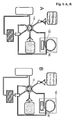
- a first aspect of the invention is a device with a fluid system (FS), comprising means for producing fluidic connections (30), a first and a second inlet (10, 20), at least one pressure generating means (40), an injection device (50), two reservoirs (60, 70) for a first and a second mobile phase (65, 75) in liquid state, a receptacle (80), an extractor (90), an outlet (100) and a means suitable for producing two different ones fluid communication states (switching unit, 110), characterized in that the first inlet (10) is designed so that the HFS under pressure, the first mobile phase (65) from the first reservoir (60) can be supplied via a fluidic connection; the first inlet (10) is further fluidly connected to an injection device (50), the injection device being adapted to introduce a mixture (120) of liquid sample material (121) and microparticles (122) suspended therein through the device Inlet introduced first mobile phase allowed; the second inlet (20) is configured so that the second mobile phase (75) can be supplied under pressure from the second reservoir
- Another aspect of the invention is the use of the device according to the invention for the manipulation of magnetic microparticles and two different mobile phases with liquid state of matter.
- An aspect of the invention is further a method for preparing a purified analyte from a complex liquid sample material containing said analyte, comprising the steps of (a) contacting the liquid sample material (121) containing the analyte with microparticles (122) of a magnetic or paramagnetic material a functionalized surface (123), wherein the analyte adsorbs to the surface; followed by (b) introducing the sample material with the microparticles into a device according to the invention using the injection device (50); followed by (c) pumping a first mobile phase (65) from a first storage vessel (60) into the first inlet (10) of the device, wherein the switching unit (110) of the device establishes the connection state (I) and in the extractor (90) a magnetic field is applied to a first section (97a) of the line (95) therein, which is suitable for containing in the mobile phase passing through the line (95) magnetic or paramagnetic microparticles (122) on the inner wall next
- Method for detecting an analyte in a complex liquid sample material containing said analyte comprising the steps of (a) providing a device which is characterized in that the outlet (100) of the HFS with a separation unit (130) and the separation unit with a detector ( 140) is fluidically connected, and the output (145) of the detector is fluidically connected to the collecting vessel (80).
- the invention provides a fluid system with which magnetic or paramagnetic microparticles and two different mobile phases, preferably liquid phases, can be manipulated.
- the present invention is illustrated by the use of corresponding microparticles having a hydrocarbon-functionalized surface.
- Such microparticles have hitherto not been used for quantitative clinical chemical analyzes. But they have considerable advantages in the preparation of clinical sample material. These advantages are particularly evident when low molecular weight analytes, typically between 50 and 1000 daltons, are to be detected. In particular, the expert in a quantitative chromatographic analysis benefit from the use of such particles.
- magnetic or paramagnetic microparticles are brought into contact with hydrocarbon-functionalized surfaces in a reaction vessel together with liquid sample material, for example whole blood, serum, plasma or hemolyzed blood. This is followed by adsorption of the analyte from the liquid phase to the functionalized surface of the particles. After a certain residence time, solid and liquid phases are separated from each other. This may preferably be done by removing the liquid phase from the vessel while the particles are retained by a magnetic field in the vessel. For example, a permanent magnet can be brought from the outside against the wall of the vessel, so that the magnetic particles are immobilized at this point on the vessel inner wall. The particles can then be washed.
- liquid sample material for example whole blood, serum, plasma or hemolyzed blood.
- the magnet can be removed, for example, and then the particles are resuspended in a washing buffer. After re-immobilizing the particles and removing the wash buffer, the analyte is eluted from the surface of the particles by contacting the microparticles with a solvent suitable for the desorption of the analyte. After separation of solid and liquid phase, the analyte can be detected from the solvent with the aid of chromatographic methods.
- the direct automation of the manual operations as described above does not yet sufficiently overcome the disadvantages of the prior art.
- the present invention describes a possibility of automating the extraction in a liquid system, preferably a high-pressure liquid system, which surprisingly offers many advantages.
- the device according to the invention makes do with a minimum of moving parts and thus makes the use of complicated, in three dimensions movable pipetting or expensive vacuum systems superfluous.
- a particularly preferred embodiment of the present invention is a substantially closed high pressure fluid system and the use thereof for the manipulation of magnetic or paramagnetic microparticles suspended in liquid sample material and two different mobile phases.
- a largely closed system in the sense of the present The invention is a high pressure fluid system in which there is no operationally open connection between the space filled by the mobile phases and the environment.
- the high-pressure fluid system according to the invention is a largely closed system, since it has an injection device by means of which a mixture of liquid sample material and extraction particles can be introduced into the fluid system in a controlled manner.
- the first mobile phase is chosen so that it can be separated from extraction particles and other sample material.
- “remaining sample material” means that material from the liquid sample from which at least portions of the analyte contained therein have been extracted by adsorption onto the extraction particles.
- the second mobile phase With the second mobile phase, the analyte is released from the extraction particles.
- the first and second mobile phases have a liquid state of aggregation or are respectively located in the liquid aggregate state in the high-pressure liquid system according to the invention. This also implies the use of mobile phases which are volatile at room temperature and normal ambient pressure.
- the introduced material remains from the injection of the mixture of extraction particles and sample material until the chromatographic analysis of the analyte within the system.
- the described method allows in a simple manner the manipulation of magnetic or paramagnetic microparticles which are used for extractive-analytical purposes, preferably in the high-pressure liquid system according to the invention.
- An automated operation of the device according to the invention is easily possible.
- the principle of microparticle manipulation allows the construction of analytical extraction systems that require a minimum of moving parts. Particularly expensive xyz pipetting units or vacuum systems are no longer required, in contrast to previously used automated extraction systems.
- the system according to the invention can be configured extremely compact and the demand for solid or liquid consumables is minimized.
- the construction of a closed system allows the use of liquid phases with a comparatively high vapor pressure, which in open systems such as Pipetting leads to problems, for example due to the build-up of pressure by evaporation of the liquid phase in the pipette chamber.
- the system according to the invention also enables very short cycle times and thus a high sample throughput.
- FIG. 2 The structure of a particularly preferred device according to the invention is in FIG. 2 shown.
- the device can be constructed largely from commercially available HPLC components.
- One component with a special function is the extractor (90).
- this is a toroidal transformer which builds up a strong magnetic field under current flow and on which an HPLC line is fixed in the form of a loop ( FIG. 7 ).
- Very particular preference is given to an HPLC line with an internal diameter of between 0.2 mm and 2.0 mm.
- Preferred materials for the conduit are polyphenylsulfone (PPSU), polyetheretherketone (PEEK) and silicone.
- serum is mixed with a suspension of C18 functionalized ferromagnetic microparticles (extraction particles).
- C18 functionalized ferromagnetic microparticles extraction particles
- low-polar analyte molecules are adsorbed to the hydrophobic chains of the microparticles.
- the mixture of sample and particles is injected via an injection valve into the device according to the invention.
- the first mobile phase of this system is an aqueous solution.
- the mixture of sample and particles is transferred to an electromagnet.
- the loaded with analyte ferromagnetic particles in the tube system using the activated Electromagnets retained and immobilized.
- the non-particle-bound sample matrix is transported by the continuous stream of the first mobile phase into the collecting vessel (waste).
- the aqueous mobile phase in the tube system is now replaced by an organic solvent as the second mobile phase.
- the electromagnet is de-energized; In the loop of the extractor resuspends the particles in the organic solvent and the detachment of the target analyte from the functionalized particles. After a few seconds, the electromagnet is switched on again, the particles that are now mobile in the loop are immobilized again. The cell eluted from the particles Zeilanalyt molecules are transferred directly to an analytical chromatography column. This separation column is followed by a chromatographic detector. On the basis of this working principle, the prototype of an extraction system was manufactured, the extractor in FIG. 7 is shown.
- the antimicrobial drug Itraconazole was considered.
- the quantification of this substance in the therapeutic concentration range from human sample matrix was carried out.
- serum samples with known itraconazole concentrations determined by means of LC tandem mass spectrometry and "drug-free" sera were investigated.
- C18-modified magnetic or paramagnetic extraction particles from Dynal (Oslo, Norway) were used (Dynabeads® 18, 50 mg / ml). 15 ⁇ l of this bead suspension were pipetted into a reaction vessel; this was positioned on a permanent magnetic particle extractor (Dynal MPC-S Magnetic Particle Concentrator). The particle-free dissolution medium was lifted off. The particles were then washed twice with 200 ⁇ l each of 0.1% trichloroacetic acid; For this purpose, the reaction vessel was repeatedly removed from the extractor and positioned again in order to immobilize the particles so. Finally, the particles were suspended in 1000 ⁇ l of water.
- Figures 8 AC show exemplary chromatograms for the analysis of a blank sample (a), a calibrator sample (b) with an itraconazole concentration of 2.9 mg / l, and a pooled patient sample (c). If the patient sample is quantified using the calibrator sample, a concentration of 2.0 mg / l is calculated. The same result was found for this sample by means of a recognized mass spectrometric analysis method for the determination of itraconazole ( Vogeser M, Spschreiber U, Schiel X. Determination of itraconazole and hydroxyitraconazole in plasma by means of liquid chromatography-tandem mass spectrometry with on-line solid-phase extraction. Clin Chem Lab Med 2003; 41: 915-20 ).
Abstract
Description
Die vorliegende Erfindung beschäftigt sich mit der Automatisierung von Extraktionsprozessen mittels magnetischer Mikropartikel mit funktionalisierter Oberfläche.The present invention is concerned with the automation of extraction processes using functionalized surface magnetic microparticles.
Für einen Großteil in-vitro diagnostischer Untersuchungen ist es erforderlich, einen oder mehrere Zielanalyten aus komplexen Probenmaterialien (Serum, Plasma, Vollblut, Urin etc.) zu extrahieren. Hierbei werden die jeweiligen Zielanalyte durch unterschiedliche Verfahren angereichert, während Komponenten der Probenmatrix, die die nachfolgende Analyse behindern würden (z. B. Proteine, Peptide, Salze), abgereichert werden. Folgende Extraktionsverfahren werden bislang für die Anreicherung von Zielanalyten eingesetzt: Proteinfällung mit organischen Lösungsmitteln oder Säuren; flüssig-flüssig Extraktion (solvent extraction) mit einem Evaporationsschritt; Festphasen-Extraktion an Kartuschen, die Partikel mit definierten Oberflächenstrukturen beinhalten (vor allem kohlenwasserstofffunktionalisierte Silica-Partikel; solid phase extraction, SPE).For the majority of in vitro diagnostic studies, it is necessary to extract one or more target analytes from complex sample materials (serum, plasma, whole blood, urine, etc.). In this case, the respective target analytes are enriched by different methods, while components of the sample matrix which would hinder the subsequent analysis (for example proteins, peptides, salts) are depleted. The following extraction methods have hitherto been used for the enrichment of target analytes: protein precipitation with organic solvents or acids; liquid-liquid extraction (solvent extraction) with an evaporation step; Solid-phase extraction on cartridges containing particles with defined surface structures (especially hydrocarbon-functionalized silica particles, solid phase extraction, SPE).
Aus dem Stand der Technik bekannte Extraktionsverfahren sind mit einem hohen manuellen Arbeitsaufwand verbunden. Verfahren zur Automatisierung solcher Extraktionsprozesse sind bislang technisch aufwändig und weisen zahlreiche Nachteile auf. Sie erfordern einerseits anspruchsvolle mechanische Konstruktionen, z. B. Pipettiersysteme und/oder Vakuumsysteme. Andererseits besteht für bekannte Verfahren ein hoher Bedarf an festen und flüssigen Verbrauchsmaterialien, z. B. Extraktionskartuschen, Extraktionsplatten, Lösungsmittel. Darüber hinaus erfordern sie eine lange Bearbeitungsdauer und sind charakterisiert durch geringen Probendurchsatz und begrenzte Serienlängen.Extraction methods known from the prior art are associated with a high manual workload. Methods for the automation of such extraction processes have hitherto been technically complicated and have numerous disadvantages. On the one hand they require sophisticated mechanical constructions, eg. B. pipetting systems and / or vacuum systems. On the other hand, there is a high demand for solid and liquid consumables for known processes, for. As extraction cartridges, extraction plates, solvents. In addition, they require a long processing time and are characterized by low sample throughput and limited series lengths.
Ein wichtiges Ziel der Arbeiten zur vorliegenden Erfindung ist es gewesen, ein Extraktionssystem zu entwickeln, das in Kombination mit einem Trenn- und Analysesystem ein weitgehend geschlossenes System bildet. Mit dem erfindungsgemäßen Flüssigkeitssystem, das bevorzugt ein Hochdruck-Flüssigkeitssystem ist, werden die Limitierungen gegenwärtig vorhandener automatisierter Extraktionsprozesse überwunden.An important aim of the work of the present invention has been to develop an extraction system which, in combination with a separation and analysis system, forms a largely closed system. With the liquid system according to the invention, which is preferably a high-pressure liquid system, the limitations of currently existing automated extraction processes are overcome.
Ein erster Aspekt der Erfindung ist eine Vorrichtung mit einem Flüssigkeitssystem (FS), umfassend Mittel zur Herstellung fluidischer Verbindungen (30), einen ersten und einen zweiten Einlass (10, 20), mindestens ein Druckerzeugungsmittel (40), eine Injektionsvorrichtung (50), zwei Vorratsbehälter (60, 70) für eine erste und eine zweite mobile Phase (65, 75) mit flüssigem Aggregatzustand, ein Auffanggefäß (80), einen Extraktor (90), einen Auslass (100) und ein Mittel geeignet zur Herstellung von zwei verschiedenen fluiden Verbindungszuständen (Schalteinheit, 110), dadurch gekennzeichnet, dass der erste Einlass (10) so ausgeführt ist, dass dem HFS unter Druck die erste mobile Phase (65) aus dem ersten Vorratsbehälter (60) über eine fluidische Verbindung zuführt werden kann; der erste Einlass (10) weiterhin mit einer Injektionsvorrichtung (50) fluidisch verbunden ist, wobei die Injektionsvorrichtung so ausgeführt ist, dass sie das Einbringen einer Mischung (120) aus flüssigem Probenmaterial (121) und darin suspendierten Mikropartikeln (122) in die durch den Einlass eingebrachte erste mobile Phase erlaubt; der zweite Einlass (20) so ausgeführt ist, dass dem HFS unter Druck die zweite mobile Phase (75) aus dem zweiten Vorratsbehälter (70) über eine fluidische Verbindung zuführt werden kann; der erste Einlass (10) mit einem ersten Eingang (E1) der Schalteinheit (110) und der zweite Einlass (20) mit einem zweiten Eingang (E2) der Schalteinheit fluidisch verbunden sind; der Extraktor (90) über einen Eingang (91) und einen Ausgang (92) verfügt, wobei der Eingang (91) des Extraktors mit einem ersten Ausgang (A1) der Schalteinheit fluidisch verbunden ist und der Ausgang (92) des Extraktors mit einem dritten Eingang (E3) der Schalteinheit fluidisch verbunden ist; der Extraktor ferner eine fluidisch verbindende Leitung (95) zwischen dem Eingang (91) und dem Ausgang (92) umfasst, ferner eine steuerbare Vorrichtung (96), mit der an zwei oder mehr hintereinander angeordneten Abschnitten (97a, 97b) dieser Leitung zeitweilig ein lokales Magnetfeld angelegt werden kann; der zweite Ausgang (A2) der Schalteinheit (110) der Auslass (100) ist oder fluidisch mit dem Auslass (100) verbunden ist; der dritte Ausgang (A3) der Schalteinheit (110) mit dem Auffanggefäß (80) fluidisch verbunden ist; und die Schalteinheit (110) dazu geeignet ist, im ersten Verbidungszustand (I) E1 und A1, E2 und A2 sowie E3 und A3 fluidisch zu verbinden und im zweiten Verbidungszustand (II) E2 und A1, E3 und A2 sowie E1 und A3 fluidisch zu verbinden.A first aspect of the invention is a device with a fluid system (FS), comprising means for producing fluidic connections (30), a first and a second inlet (10, 20), at least one pressure generating means (40), an injection device (50), two reservoirs (60, 70) for a first and a second mobile phase (65, 75) in liquid state, a receptacle (80), an extractor (90), an outlet (100) and a means suitable for producing two different ones fluid communication states (switching unit, 110), characterized in that the first inlet (10) is designed so that the HFS under pressure, the first mobile phase (65) from the first reservoir (60) can be supplied via a fluidic connection; the first inlet (10) is further fluidly connected to an injection device (50), the injection device being adapted to introduce a mixture (120) of liquid sample material (121) and microparticles (122) suspended therein through the device Inlet introduced first mobile phase allowed; the second inlet (20) is configured so that the second mobile phase (75) can be supplied under pressure from the second reservoir (70) to the HFS via a fluidic connection; the first inlet (10) is fluidically connected to a first input (E1) of the switching unit (110) and the second inlet (20) is fluidly connected to a second input (E2) of the switching unit; the extractor (90) has an inlet (91) and an outlet (92), the inlet (91) of the extractor being fluidically connected to a first outlet (A1) of the switching unit and the outlet (92) of the extractor being connected to a third Input (E3) of the switching unit is fluidly connected; the extractor further comprises a fluidically connecting line (95) between the inlet (91) and the outlet (92), further comprising a controllable device (96) with which one or more sections (97a, 97b) of this line are arranged in succession local magnetic field can be applied; the second output (A2) of the switching unit (110) is the outlet (100) or is fluidly connected to the outlet (100); the third output (A3) of the switching unit (110) is fluidically connected to the collecting vessel (80); and the switching unit (110) is adapted to fluidly connect E1 and A1, E2 and A2 as well as E3 and A3 in the first connection state (I) and fluidly to E2 and A1, E3 and A2 as well as E1 and A3 in the second connection state (II) connect.
Ein weiterer Aspekt der Erfindung ist die Verwendung der erfindungsgemäßen Vorrichtung für die Manipulation von magnetischen Mikropartikeln und zwei verschiedenen mobilen Phasen mit flüssigem Aggregatzustand.Another aspect of the invention is the use of the device according to the invention for the manipulation of magnetic microparticles and two different mobile phases with liquid state of matter.
Ein Aspekt der Erfindung ist ferner eine Methode zur Darstellung eines gereinigten Analyten aus einem komplexen flüssigen Probenmaterial enthaltend besagten Analyten, umfassend die Schritte (a) Inkontaktbringen des flüssigen Probenmaterials (121) enthaltend den Analyten mit Mikropartikeln (122) aus einem magnetischen oder paramagnetischen Material mit einer funktionalisierten Oberfläche (123), wobei der Analyt an die Oberfläche adsorbiert; gefolgt von (b) Einbringen des Probenmaterials mit den Mikropartikeln in eine erfindungsgemäße Vorrichtung unter Verwendung der Injektionsvorrichtung (50); gefolgt von (c) Einpumpen einer ersten mobilen Phase (65) aus einem ersten Vorratsgefäß (60) in den ersten Einlass (10) der Vorrichtung, wobei die Schalteinheit (110) der Vorrichtung den Verbindungszustand (I) herstellt und im Extraktor (90) an einem ersten Abschnitt (97a) der darin befindlichen Leitung (95) ein Magnetfeld angelegt wird, das geeignet ist, in der durch die Leitung (95) gelangenden mobilen Phase enthaltene magnetische oder paramagnetische Mikropartikel (122) an der dem Magnetfeld nächst zugewandten Innenwand (93) der Leitung (95) im ersten Abschnitt (97a) zu immobilisieren; gefolgt von (d) Immobilisieren der Mikropartikel (122) im Extraktor (90) in dem ersten Abschnitt (97a) der Innenwand (93) der Leitung (95); gefolgt von (e) Trennen der Mikropartikel (122) vom übrigen Probenmaterial durch weiteres Einpumpen der ersten mobilen Phase (65) aus dem ersten Vorratsgefäß (60) in den ersten Einlass (10), wobei die immobilisierten Mikropartikel gewaschen werden und das übrige Probenmaterial dem Auffangbehälter (80) zugeführt wird; gefolgt von (f) Umschalten der Schalteinheit (110) in den Verbindungszustand (II) und Einpumpen einer zweiten mobilen Phase (75) aus dem zweiten Vorratsgefäß (70) in den zweiten Einlass (20) der Vorrichtung, wobei die zweite mobile Phase (75) geeignet ist, den adsorbierten Analyten von der Oberfläche der Mikropartikel (122) zu lösen; gefolgt von (g) Eluieren des Analyten durch Inkontaktbringen der Mikropartikel (122) mit der zweiten mobilen Phase (75), wobei gleichzeitig das Magnetfeld vom ersten Abschnitt (97a) der Leitung (95) im Extraktor (90) abgeschwächt oder entfernt wird und die Mikropartikel (122) in der Leitung (95) durch die Bewegung der mobilen Phase (75) in Richtung eines zweiten Abschnitts (97b) der Leitung (95) bewegt werden; (h) Anlegen eines Magnetfelds an dem zweiten Abschnitt (97b) der Leitung (95), wobei das Magnetfeld geeignet ist, in der durch die Leitung (95) gelangenden mobilen Phase enthaltene magnetische oder paramagnetische Mikropartikel (122) an der dem Magnetfeld nächst zugewandten Innenwand (93) der Leitung (95) im zweiten Abschnitt (97b) zu immobilisieren; gefolgt von (i) Immobilisieren der Mikropartikel (122) an der Innenwand (93) in dem zweiten Abschnitt (97b) der Leitung; gefolgt von (k) Bewegen der zweiten mobilen Phase mit dem eluierten Analyten zum Auslass (100) der Vorrichtung durch weiteres Einpumpen der zweiten mobilen Phase (75) aus dem zweiten Vorratsgefäß (70) in den zweiten Eingang (20), wodurch der Analyt am Auslass (100) gereinigt dargestellt wird.An aspect of the invention is further a method for preparing a purified analyte from a complex liquid sample material containing said analyte, comprising the steps of (a) contacting the liquid sample material (121) containing the analyte with microparticles (122) of a magnetic or paramagnetic material a functionalized surface (123), wherein the analyte adsorbs to the surface; followed by (b) introducing the sample material with the microparticles into a device according to the invention using the injection device (50); followed by (c) pumping a first mobile phase (65) from a first storage vessel (60) into the first inlet (10) of the device, wherein the switching unit (110) of the device establishes the connection state (I) and in the extractor (90) a magnetic field is applied to a first section (97a) of the line (95) therein, which is suitable for containing in the mobile phase passing through the line (95) magnetic or paramagnetic microparticles (122) on the inner wall next to the magnetic field ( 93) of the conduit (95) in the first section (97a); followed by (d) immobilizing the microparticles (122) in the extractor (90) in the first portion (97a) of the inner wall (93) of the conduit (95); followed by (e) separating the microparticles (122) from the remainder of the sample material by further pumping the first mobile phase (65) from the first storage vessel (60) into the first inlet (10), washing the immobilized microparticles and the remainder of the sample material Receiving container (80) is supplied; followed by (f) switching the switching unit (110) to the connection state (II) and pumping a second mobile phase (75) from the second storage vessel (70) into the second inlet (20) of the device, the second mobile phase (75 ) is capable of dissolving the adsorbed analyte from the surface of the microparticles (122); followed by (g) eluting the analyte by contacting the microparticles (122) with the second mobile phase (75) while simultaneously attenuating or removing the magnetic field from the first portion (97a) of the conduit (95) in the extractor (90); Microparticles (122) in the conduit (95) are moved by the movement of the mobile phase (75) towards a second portion (97b) of the conduit (95); (h) applying a magnetic field to the second portion (97b) of the conduit (95), wherein the magnetic field is suitable, in which through the conduit (95) reaching mobile phase containing magnetic or paramagnetic microparticles (122) on the magnetic field next facing inner wall (93) of the conduit (95) in the second section (97b) to immobilize; followed by (i) immobilizing the microparticles (122) on the inner wall (93) in the second portion (97b) of the conduit; followed by (k) moving the second mobile phase with the eluted analyte to the outlet (100) of the device by further pumping the second mobile phase (75) from the second storage vessel (70) into the second inlet (20), whereby the analyte at Outlet (100) is shown cleaned.
Methode zur Detektion eines Analyten in einem komplexen flüssigen Probenmaterial enthaltend besagten Analyten, umfassend die Schritte (a) Bereitstellen einer Vorrichtung, die dadurch gekennzeichnet ist, dass der Auslass (100) des HFS mit einer Trenneinheit (130) und die Trenneinheit mit einem Detektor (140) fluidisch verbunden ist, und der Ausgang (145) des Detektors mit dem Auffanggefäß (80) fluidisch verbunden ist. (b) Darstellung des gereinigten Analyten aus dem Probenmaterial unter Verwendung einer erfindungsgemäßen Vorrichtung, wobei der Analyt am Auslass (100) der Vorrichtung gereinigt dargestellt wird und die Schalteinheit (110) den Verbindungszustand (II) herstellt; (c) Bewegen der zweiten mobilen Phase mit (i) dem Analyten und (ii) gegebenenfalls zusammen mit dem Analyt eluierten weiteren Substanzen durch die Trenneinheit (130) und in den Detektor (140), wobei die Bewegung getrieben wird durch Einpumpen der zweiten mobilen Phase (75) aus dem zweiten Vorratsgefäß (70) in den zweiten Eingang (20); (d) Detektion des Analyten durch den Detektor (140).Method for detecting an analyte in a complex liquid sample material containing said analyte, comprising the steps of (a) providing a device which is characterized in that the outlet (100) of the HFS with a separation unit (130) and the separation unit with a detector ( 140) is fluidically connected, and the output (145) of the detector is fluidically connected to the collecting vessel (80). (b) depicting the purified analyte from the sample material using a device according to the invention, wherein the analyte is rendered purified at the outlet (100) of the device and the switching unit (110) establishes the connection state (II); (c) moving the second mobile phase with (i) the analyte and (ii) optionally further eluted along with the analyte further substances through the separation unit (130) and into the detector (140), wherein the movement is driven by pumping the second mobile Phase (75) from the second storage vessel (70) in the second input (20); (d) Detection of the analyte by the detector (140).
Die Erfindung stellt ein Flüssigkeitssystem zur Verfügung, mit dem magnetische oder paramagnetische Mikropartikel und zwei verschiedene mobile Phasen, bevorzugt Flüssigphasen, manipuliert werden können. Beispielhaft wird die vorliegende Erfindung illustriert anhand der Verwendung entsprechender Mikropartikel mit kohlenwasserstoff-funktionalisierter Oberfläche. Solche Mikropartikel finden bislang keinen Einsatz für quantitative klinisch-chemische Analysen. Sie haben aber erhebliche Vorteile bei der Aufbereitung klinischen Probenmaterials. Diese Vorteile zeigen sich besonders dann, wenn Analyten mit einem niedrigen Molekulargewicht, typischerweise zwischen 50 und 1000 Dalton, nachgewiesen werden sollen. Insbesondere kann der Fachmann bei einer quantitativ chromatographischen Analyse von der Verwendung solcher Partikel profitieren.The invention provides a fluid system with which magnetic or paramagnetic microparticles and two different mobile phases, preferably liquid phases, can be manipulated. By way of example, the present invention is illustrated by the use of corresponding microparticles having a hydrocarbon-functionalized surface. Such microparticles have hitherto not been used for quantitative clinical chemical analyzes. But they have considerable advantages in the preparation of clinical sample material. These advantages are particularly evident when low molecular weight analytes, typically between 50 and 1000 daltons, are to be detected. In particular, the expert in a quantitative chromatographic analysis benefit from the use of such particles.
Zur Probenaufarbeitung werden im einfachen Fall magnetische oder paramagnetische Mikropartikel (Extraktionspartikel) mit kohlenwasserstofffunktionalisierten Oberflächen in einem Reaktionsgefäß zusammen mit flüssigem Probenmaterial, beispielsweise Vollblut, Serum, Plasma oder hämolysiertem Blut in Kontakt gebracht. Daraufhin erfolgt eine Adsorption des Analyten aus der Flüssigphase an die funktionalisierte Oberfläche der Partikel. Nach einer gewissen Verweilzeit werden feste und flüssige Phase voneinander getrennt. Dies kann bevorzugt durch Entfernen der Flüssigphase aus dem Gefäß erfolgen, während die Partikel durch ein Magnetfeld im Gefäß zurück gehalten werden. Beispielsweise kann ein Permanentmagnet von außen an die Wand des Gefäßes gebracht werden, so dass die magnetischen Teilchen an dieser Stelle an der Gefäßinnenwand immobilisiert werden. Die Partikel können anschließend gewaschen werden. Hierzu kann der Magnet beispielsweise entfernt und die Partikel daraufhin in einem Waschpuffer resuspendiert werden. Nach erneuter Immobilisierung der Partikel und Entfernung des Waschpuffers wird der Analyt von der Oberfläche der Partikel eluiert durch Inkontaktbringen der Mikropartikel mit einem für die Desorption des Analyten geeigneten Lösungsmittel. Nach Trennung von Fest- und Flüssigphase kann der Analyt aus dem Lösungsmittel unter Zuhilfenahme chromatografischer Methoden nachgewiesen werden.For sample processing, in the simple case, magnetic or paramagnetic microparticles (extraction particles) are brought into contact with hydrocarbon-functionalized surfaces in a reaction vessel together with liquid sample material, for example whole blood, serum, plasma or hemolyzed blood. This is followed by adsorption of the analyte from the liquid phase to the functionalized surface of the particles. After a certain residence time, solid and liquid phases are separated from each other. This may preferably be done by removing the liquid phase from the vessel while the particles are retained by a magnetic field in the vessel. For example, a permanent magnet can be brought from the outside against the wall of the vessel, so that the magnetic particles are immobilized at this point on the vessel inner wall. The particles can then be washed. For this purpose, the magnet can be removed, for example, and then the particles are resuspended in a washing buffer. After re-immobilizing the particles and removing the wash buffer, the analyte is eluted from the surface of the particles by contacting the microparticles with a solvent suitable for the desorption of the analyte. After separation of solid and liquid phase, the analyte can be detected from the solvent with the aid of chromatographic methods.
Die direkte Automatisierung der manuell durchgeführten Arbeitsschritte wie oben beschrieben beseitigt die Nachteile des Standes der Technik noch nicht in befriedigender Weise. Die vorliegende Erfindung beschreibt dagegen eine Möglichkeit der Automatisierung der Extraktion in einem Flüssigkeitssystem, bevorzugt einem Hochdruck-Flüssigkeitssystem, das überraschenderweise viele Vorteile bietet. Insbesondere kommt die erfindungsgemäße Vorrichtung mit einem Minimum an beweglichen Teilen aus und macht so die Verwendung von komplizierten, in drei Dimensionen bewegbaren Pipettiereinheiten oder aufwändigen Vakuumsystemen überflüssig.The direct automation of the manual operations as described above does not yet sufficiently overcome the disadvantages of the prior art. By contrast, the present invention describes a possibility of automating the extraction in a liquid system, preferably a high-pressure liquid system, which surprisingly offers many advantages. In particular, the device according to the invention makes do with a minimum of moving parts and thus makes the use of complicated, in three dimensions movable pipetting or expensive vacuum systems superfluous.
Eine besonders bevorzugte Ausführungsform der vorliegenden Erfindung ist ein weitgehend geschlossenes Hochdruck-Flüssigkeitssystem und die Verwendung desselben zur Manipulation von in flüssigem Probenmaterial suspendierten magnetischen oder paramagnetischen Mikropartikeln und zwei verschiedenen mobilen Phasen. Ein weitgehend geschlossenes System im Sinne der vorliegenden Erfindung ist ein Hochdruck-Flüssigkeitssystem, bei dem zwischen dem von den mobilen Phasen ausgefüllten Raum und der Umgebung keine betriebsmäßig offene Verbindung besteht. Das erfindungsgemäße Hochdruck-Flüssigkeitssystem ist ein weitgehend geschlossenes System, da es über eine Injektionsvorrichtung verfügt, mittels derer sich in kontrollierter Weise ein Gemisch von flüssigem Probenmaterial und Extraktionspartikeln in das Flüssigkeitssystem einbringen lässt.A particularly preferred embodiment of the present invention is a substantially closed high pressure fluid system and the use thereof for the manipulation of magnetic or paramagnetic microparticles suspended in liquid sample material and two different mobile phases. A largely closed system in the sense of the present The invention is a high pressure fluid system in which there is no operationally open connection between the space filled by the mobile phases and the environment. The high-pressure fluid system according to the invention is a largely closed system, since it has an injection device by means of which a mixture of liquid sample material and extraction particles can be introduced into the fluid system in a controlled manner.
Erfindungsgemäß finden zwei unterschiedliche mobile Phasen Anwendung. Die erste mobile Phase wird so gewählt, dass mit ihr eine Trennung von Extraktionspartikeln und übrigem Probenmaterial erfolgen kann. In diesem Zusammenhang bedeutet "übriges Probenmaterial" dasjenige Material aus der flüssigen Probe, aus dem zumindest Anteile des darin enthaltenden Analyten durch Adsorption an die Extraktionspartikel extrahiert wurden. Mit der zweiten mobilen Phase wird der Analyt von den Extraktionspartikeln gelöst. Dabei ist es bevorzugt dass die erste und zweite mobile Phase flüssigen Aggregatzustand aufweisen bzw. im erfindungsgemäßen Hochdruck-Flüssigkeitssystem jeweils sich im flüssigen Aggregatzutand befinden. Dies impliziert auch die Verwendung von mobilen Phasen, die bei Raumtemperatur und normalem Umgebungsdruck flüchtig sind.According to the invention, two different mobile phases are used. The first mobile phase is chosen so that it can be separated from extraction particles and other sample material. In this context, "remaining sample material" means that material from the liquid sample from which at least portions of the analyte contained therein have been extracted by adsorption onto the extraction particles. With the second mobile phase, the analyte is released from the extraction particles. In this case, it is preferred that the first and second mobile phases have a liquid state of aggregation or are respectively located in the liquid aggregate state in the high-pressure liquid system according to the invention. This also implies the use of mobile phases which are volatile at room temperature and normal ambient pressure.
Bei Verwendung des erfindungsgemäßen Hochdruck-Flüssigkeitsystems verbleibt das eingebrachte Material ab der der Injektion des Gemisches aus Extraktionspartikeln und Probenmaterial bis zur chromatographischen Analyse des Analyten innerhalb des Systems.When using the high-pressure liquid system according to the invention, the introduced material remains from the injection of the mixture of extraction particles and sample material until the chromatographic analysis of the analyte within the system.
Das beschriebene Verfahren erlaubt auf einfache Weise die Manipulation von magnetischen oder paramagnetischen Mikropartikeln, die zu extraktiv-analytischen Zwecken verwendet werden, bevorzugt im erfindungsgemäßen Hochdruck-Flüssigkeitssystem. Ein automatisierter Betrieb der erfindungsgemäßen Vorrichtung ist leicht möglich. Durch das Prinzip der Manipulation der Mikropartikel ist der Aufbau von analytischen Exktraktions-Systemen möglich, bei denen ein Minimum an bewegten Bauteilen eingesetzt werden müssen. Insbesondere aufwändige x-y-z-Pipettierungseinheiten oder Vakuumsysteme sind im Gegensatz zu bisher gebräuchlichen automatisierten Extraktionssystemen nicht mehr erforderlich. Das erfindungsgemäße System kann darüber hinaus außerordentlich kompakt konfiguriert werden und der Bedarf an festen bzw. flüssigen Verbrauchsmaterialien ist minimiert. Weiterhin ermöglicht der Aufbau eines geschlossenen Systems die Verwendung von Flüssigphasen mit einem vergleichsweise hohen Dampfdruck, der bei offenen Systemen wie Pipettierautomaten zu Problemen führt, beispielsweise infolge des Aufbaus von Druck durch Verdampfen der Flüssigphase in der Pipettenkammer. Verglichen mit bisherigen Systemen werden durch das erfindungsgemäße System auch sehr kurze Zykluszeiten und dadurch ein hoher Probendurchsatz ermöglicht.The described method allows in a simple manner the manipulation of magnetic or paramagnetic microparticles which are used for extractive-analytical purposes, preferably in the high-pressure liquid system according to the invention. An automated operation of the device according to the invention is easily possible. The principle of microparticle manipulation allows the construction of analytical extraction systems that require a minimum of moving parts. Particularly expensive xyz pipetting units or vacuum systems are no longer required, in contrast to previously used automated extraction systems. Moreover, the system according to the invention can be configured extremely compact and the demand for solid or liquid consumables is minimized. Furthermore, the construction of a closed system allows the use of liquid phases with a comparatively high vapor pressure, which in open systems such as Pipetting leads to problems, for example due to the build-up of pressure by evaporation of the liquid phase in the pipette chamber. Compared with previous systems, the system according to the invention also enables very short cycle times and thus a high sample throughput.
Der Aufbau einer besonders bevorzugten erfindungsgemäßen Vorrichtung ist in
Im Detail enthält die Erfindung die folgenden Aspekte:
- 1. Vorrichtung mit einem Flüssigkeitssystem (FS) gemäß
Figur 1- der erste Einlass (10) so ausgeführt ist, dass dem HFS unter Druck die erste mobile Phase (65) aus dem ersten Vorratsbehälter (60) über eine fluidische Verbindung zuführt werden kann;
- der erste Einlass (10) weiterhin mit einer Injektionsvorrichtung (50) fluidisch verbunden ist, wobei die Injektionsvorrichtung so ausgeführt ist, dass sie das Einbringen einer Mischung (120) aus flüssigem Probenmaterial (121) und darin suspendierten Mikropartikeln (122) in die durch den Einlass eingebrachte erste mobile Phase erlaubt;
- der zweite Einlass (20) so ausgeführt ist, dass dem HFS unter Druck die zweite mobile Phase (75) aus dem zweiten Vorratsbehälter (70) über eine fluidische Verbindung zuführt werden kann;
- der erste Einlass (10) mit einem ersten Eingang (E1) der Schalteinheit (110) und der zweite Einlass (20) mit einem zweiten Eingang (E2) der Schalteinheit fluidisch verbunden sind;
- der Extraktor (90) über einen Eingang (91) und einen Ausgang (92) verfügt, wobei der Eingang (91) des Extraktors mit einem ersten Ausgang (A1) der Schalteinheit fluidisch verbunden ist und der Ausgang (92) des Extraktors mit einem dritten Eingang (E3) der Schalteinheit fluidisch verbunden ist;
- der Extraktor ferner eine fluidisch verbindende Leitung (95) zwischen dem Eingang (91) und dem Ausgang (92) umfasst, ferner eine steuerbare Vorrichtung (96), mit der an zwei oder mehr hintereinander angeordneten Abschnitten (97) dieser Leitung zeitweilig ein lokales Magnetfeld angelegt werden kann;
- der zweite Ausgang (A2) der Schalteinheit (110) der Auslass (100) ist oder fluidisch mit dem Auslass (100) verbunden ist;
- der dritte Ausgang (A3) der Schalteinheit (110) mit dem Auffanggefäß (80) fluidisch verbunden ist; und
- die Schalteinheit (110) dazu geeignet ist, im ersten Verbidungszustand (I) E1 und A1, E2 und A2 sowie E3 und A3 (auch als Stellung (I) bezeichnet) fluidisch zu verbinden und im zweiten Verbidungszustand (II) E2 und A1, E3 und A2 sowie E1 und A3 (auch als Stellung (II) bezeichnet) fluidisch zu verbinden.
- 2.
Vorrichtung gemäß Punkt 1 undFigur 2 , dadurch gekennzeichnet, dass das FS ein Hochdruck-FS (HFS) ist, das HFS bevorzugt ein weitgehend geschlossenes System ist und der Auslass (100) mit einer Trenneinheit (130) und die Trenneinheit mit einem Detektor (140) fluidisch verbunden ist, und der Ausgang (145) des Detektors mit dem Auffanggefäß (80) fluidisch verbunden ist. - 3. Vorrichtung gemäß Punkt 2, dadurch gekennzeichnet, dass die Trenneinheit (130) eine Chromatografie-Säule ist.
- 4. Vorrichtung gemäß einem der Punkte 2 oder 3, dadurch gekennzeichnet, dass der Detektor (140) ausgewählt ist aus der Gruppe bestehend aus UV/Vis-Spektrometer, Diodenarray-Detektor, Lichtstreudetektor, Fluoreszenzdetektor, Brechungsindexdetektor, Massenspektrometer, Leitfähigkeitsdetektor, Elektrochemischer Detektor.
- 5. Vorrichtung gemäß einem der Punkte 1
bis 4, dadurch gekennzeichnet, dass die steuerbare Vorrichtung (96) des Extraktors (90) einen Elektromagneten umfasst. - 6.
Vorrichtung gemäß Punkt 5, dadurch gekennzeichnet, dass die Leitung (95) zwischen Eingang (91) und Ausgang (92) des Extraktors (90) helikal mit einer Windung (99), auch als Schleife bezeichnet, ausgeführt ist, wobei die jeweils zum Eingang und Ausgang führenden Abschnitte (97a, 97b) der Leitung nebeneinander angeordnet sind. - 7.
Vorrichtung gemäß Punkt 6 undFigur 2B , dadurch gekennzeichnet, dass die die Leitung (95) zwischen Eingang (91) und Ausgang (92) des Extraktors (90) helikal und mit zwei oder mehr Windungen bzw. Schleifen (99a, 99b) ausgeführt ist, wobei ein oder mehrere Abschnitte (97c) der Windungen und die jeweils zum Eingang (91) und Ausgang (92) führenden Abschnitte (97a, 97b) der Leitung nebeneinander angeordnet sind. - 8. Vorrichtung gemäß einem der Punkte 5 bis 7, dadurch gekennzeichnet, dass der Elektromagnet so angeordnet ist, dass das Magnetfeld auf zwei oder mehr nebeneinander angeordnete Abschnitte (97) der Leitung (95) zwischen Eingang (91) und Ausgang (92) des Extraktors (90) wirken kann.
- 9. Vorrichtung gemäß einem der Punkte 5
bis 8, weiterhin umfassend eine Steuereinheit und dadurch gekennzeichnet, dass die Steuereinheit das Druckerzeugungsmittel (40), die Schalteinheit (110) und den Elektromagneten steuert. - 10. Vorrichtung gemäß einem der Punkte 2
bis 9, dadurch gekennzeichnet, dass das Druckerzeugungsmittel zwei HPLC-Pumpen umfasst. - 11. Vorrichtung gemäß einem der Punkte 1
bis 10, dadurch gekennzeichnet, dass das Auffanggefäß (80) einen Magneten oder Elektromagneten umfasst. - 12. Vorrichtung gemäß einem der Punkte 1
bis 11, weiterhin umfassend eine erste (65) und eine zweite (75) mobile Phase mit flüssigem Aggregatzustand. - 13. Vorrichtung gemäß einem der Punkte 1 bis 12, weiterhin umfassend magnetische oder paramagnetische Mikropartikel (122).
- 14. Vorrichtung gemäß Punkt 13, dadurch gekennzeichnet, dass die Mikropartikel eine funktionalisierte Oberfläche (123) aufweisen.
- 15. Vorrichtung gemäß Punkt 14, dadurch gekennzeichnet, dass die Oberfläche die Adsorption eines Analyten erlaubt.
- 16. Vorrichtung gemäß Punkt 15, dadurch gekennzeichnet, dass die Oberfläche der Mikropartikel hydrophob ist.
- 17. Vorrichtung gemäß Punkt 15, dadurch gekennzeichnet, dass die Oberfläche der Mikropartikel hydrophob ist.
- 18. Vorrichtung gemäß Punkt 15, dadurch gekennzeichnet, dass die Oberfläche ausgewählt ist aus der Gruppe bestehend aus Anionenaustauschermaterial, Kationenaustauschermaterial, gemischt hydrophobes und hydrophiles Kopolymer und Silica.
- 19.
Vorrichtung gemäß Punkt 17, dadurch gekennzeichnet, dass die Oberfläche C1-C50, bevorzugt C5-C20 Kohlenwasserstoffreste umfasst. - 20. Vorrichtung gemäß einem der Punkte 13 bis 19, weiterhin umfassend flüssiges Probenmaterial.
- 21.
Vorrichtung gemäß Punkt 20, durch gekennzeichnet, dass das Probenmaterial eine Suspension ist. - 22. Vorrichtung gemäß Punkt 21, durch gekennzeichnet, dass das Probenmaterial ein Homogenat ist.
- 23. Vorrichtung gemäß einem der Punkte 20 bis 22, durch gekennzeichnet, dass das Probenmaterial Nahrungsmittelbestandteile, Bestandteile einer Bodenprobe oder Abwasser enthält.
- 24.
Vorrichtung gemäß Punkt 20, durch gekennzeichnet, dass das Probenmaterial eine biologische Flüssigkeit, eine Suspension oder ein Homogenat mit biologischem Material oder ein Lysat von biologischem Material umfasst. - 25. Vorrichtung gemäß Punkt 24, durch gekennzeichnet, dass das Probenmaterial ausgewählt ist aus der Gruppe bestehend aus Vollblut, Citrat-Blut, Heparin-Blut, EDTA-Blut, Plasma, Serum, Urin, Sputum, Synovialflüsigkeit, Bronchiallavage, Atemluft-Kondensat und Liquor.
- 26. Verwendung einer Vorrichtung gemäß einem der Punkte 1 bis 25 für die Manipulation von magnetischen Mikropartikeln und zwei verschiedenen mobilen Phasen mit flüssigem Aggregatzustand.
- 27. Verwendung gemäß Punkt 26, weiterhin für die Manipulation von flüssigem Probenmaterial.
- 28. Methode zur Darstellung eines gereinigten Analyten aus einem komplexen flüssigen Probenmaterial enthaltend besagten Analyten, umfassend die Schritte
- (a) Inkontaktbringen des flüssigen Probenmaterials (121) enthaltend den Analyten mit Mikropartikeln (122) aus einem magnetischen oder paramagnetischen Material mit einer funktionalisierten Oberfläche (123), wobei der Analyt an die Oberfläche adsorbiert; gefolgt von
- (b) Einbringen des Probenmaterials mit den Mikropartikeln in eine Vorrichtung gemäß einem der Punkte 1 bis 25 unter Verwendung der Injektionsvorrichtung (50); gefolgt von
- (c) Einpumpen einer ersten mobilen Phase (65) aus dem ersten Vorratsgefäß (60) in den ersten Einlass (10) der Vorrichtung, wobei die Schalteinheit (110) der Vorrichtung den Verbindungszustand (I) herstellt und im Extraktor (90) an dem ersten Abschnitt (97a) der darin befindlichen Leitung (95) ein Magnetfeld angelegt wird, das geeignet ist, in der durch die Leitung (95) gelangenden mobilen Phase enthaltene magnetische oder paramagnetische Mikropartikel (122) an der dem Magnetfeld nächst zugewandten Innenwand (93) der Leitung (95) im ersten Abschnitt (97a) zu immobilisieren; gefolgt von
- (d) Immobilisieren der Mikropartikel (122) im Extraktor (90) an der Innenwand (93) in dem ersten Abschnitt (97a) der Leitung; gefolgt von
- (e) Trennen der Mikropartikel (122) vom übrigen Probenmaterial durch weiteres Einpumpen der ersten mobilen Phase (65) aus dem ersten Vorratsgefäß (60) in den ersten Einlass (10), wobei die immobilisierten Mikropartikel mit der ersten mobilen Phase gewaschen werden und das übrige Probenmaterial dem Auffangbehälter (80) zugeführt wird; gefolgt von
- (f) Umschalten der Schalteinheit (110) in den Verbindungszustand (II) und Einpumpen einer zweiten mobilen Phase (75) aus dem zweiten Vorratsgefäß (70) in den zweiten Einlass (20) der Vorrichtung, wobei die zweite mobile Phase (75) geeignet ist, den adsorbierten Analyten von der Oberfläche der Mikropartikel (122) zu lösen; gefolgt von
- (g) Eluieren des Analyten durch Inkontaktbringen der Mikropartikel (122) mit der zweiten mobilen Phase (75), wobei gleichzeitig das Magnetfeld vom ersten Abschnitt (97a) der Leitung (95) im Extraktor (90) abgeschwächt oder entfernt wird und die Mikropartikel (122) in der Leitung (95) durch die Bewegung der mobilen Phase (75) in Richtung eines zweiten Abschnitts (97b) der Leitung (95) bewegt werden;
- (h) Anlegen eines Magnetfelds an dem zweiten Abschnitt (97b) der Leitung (95), wobei das Magnetfeld geeignet ist, in der durch die Leitung (95) gelangenden mobilen Phase enthaltene magnetische oder paramagnetische Mikropartikel (122) an der dem Magnetfeld nächst zugewandten Innenwand (93) der Leitung (95) im zweiten Abschnitt (97b) zu immobilisieren; gefolgt von
- (i) Immobilisieren der Mikropartikel (122) an der Innenwand (93) in dem zweiten Abschnitt (97b) der Leitung; gefolgt von
- (j) Bewegen der zweiten mobilen Phase mit dem eluierten Analyten zum Auslass (100) der Vorrichtung durch weiteres Einpumpen der zweiten mobilen Phase (75) aus dem zweiten Vorratsgefäß (70) in den zweiten Eingang (20), wodurch der Analyt am Auslass (100) gereinigt dargestellt wird.
- 29. Methode gemäß Punkt 28, dadurch gekennzeichnet, dass in der Vorrichtung die Leitung (95) zwischen dem Eingang (91) und dem Ausgang (92) des Extraktors (90) helikal und mit n (n = 2 oder größer als 2) Windungen (99) ausgeführt ist, wobei n Abschnitte (97c) der Windungen und die jeweils zum Eingang (91) und Ausgang (92) führenden Abschnitte (97a, 97b) der Leitung nebeneinander angeordnet sind, das Magnetfeld auf die nebeneinander angeordnete Abschnitte der Leitung zwischen Eingang und Ausgang des Extraktors (97a, 97b, 97c) wirken kann, und Schritt (e) gefolgt wird von den Schritten (e') Waschen der Mikropartikel (122) durch weiteres Einpumpen der ersten mobilen Phase (65) in den ersten Einlass (10), wobei gleichzeitig das Magnetfeld an dem Abschnitt der Leitung im Extraktor, and dem die Mikropartikel immobilisiert sind, abgeschwächt oder entfernt wird und die Mikropartikel in der Leitung durch die Bewegung der mobilen Phase in Richtung des nächsten für eine Immobilisierung geeigneten Abschnitts bewegt werden; gefolgt von (e") erneutes Immobilisieren der Mikropartikel durch Anlegen eines Magnetfelds an den nächsten für eine Immobilisierung geeigneten Abschnitt der Leitung; wobei (e') und (e") n-1 mal durchgeführt werden können.
- 30. Methode gemäß einem der Punkte 28 und 29, dadurch gekennzeichnet, dass die erste mobile Phase Wasser oder eine wässrige Lösung ist.
- 31. Methode gemäß einem der Punkte 28
bis 30, dadurch gekennzeichnet, dass die zweite mobile Phase ein organisches Lösungsmittel ist. - 32. Methode gemäß einem der Punkte 28 bis 31, dadurch gekennzeichnet, dass die zweite mobile Phase ein unpolares organisches Lösungsmittel ist.
- 33. Methode gemäß einem der Punkte 28 bis 31, dadurch gekennzeichnet, dass die zweite mobile Phase ein polares organisches Lösungsmittel ist.
- 34. Methode gemäß einem der Punkte 28 bis 31, dadurch gekennzeichnet, dass die zweite mobile Phase ein organisches Lösungsmittel is, das ausgewählt ist aus der Gruppe bestehend aus einem C1-C6 aliphatischen Alkohol, Acetonitril, Methyl-tert-butylether (MTBE), Aceton, Ethylacetat, Hexan, Dimethylsulfoxid, Diisopropylether, Dichlormethan, Trichlormethan, und Tetrachlormethan.
- 35. Methode gemäß einem der Punkte 28 bis 34, dadurch gekennzeichnet, dass das Probenmaterial eine biologische Flüssigkeit, eine Suspension oder ein Homogenat mit biologischem Material oder ein Lysat von biologischem Material umfasst.
- 36. Methode gemäß Punkt 35, dadurch gekennzeichnet, dass das Probenmaterial ausgewählt ist aus der Gruppe bestehend aus Vollblut, Citrat-Blut, Heparin-Blut, EDTA-Blut, Plasma, Serum, Urin, Sputum, Synovialflüsigkeit, Bronchiallavage, Atemluft-Kondensat und Liquor.
- 37. Methode zur Detektion eines Analyten in einem komplexen flüssigen Probenmaterial enthaltend besagten Analyten, umfassend die Schritte
- (a) Bereitstellen einer Vorrichtung gemäß einem der Punkte 2 bis 25;
- (b) Darstellung des gereinigten Analyten aus dem Probenmaterial unter Einsatz einer Methode gemäß einem der Punkte 28 bis 36, wobei der Analyt am Auslass (100) der Vorrichtung gereinigt dargestellt wird und die Schalteinheit (110) den Verbindungszustand (II) herstellt;
- (c) Bewegen der zweiten mobilen Phase mit (i) dem Analyten und (ii) gegebenenfalls zusammen mit dem Analyt von den Mikropartikeln eluierten weiteren Substanzen durch die Trenneinheit (130) und in den Detektor (140), wobei die Bewegung getrieben wird durch Einpumpen der zweiten mobilen Phase (75) aus dem zweiten Vorratsgefäß (70) in den zweiten Eingang (20);
- (d) Detektion des Analyten durch den Detektor (140).
- 38. Methode gemäß Punkt 37, dadurch gekennzeichnet, dass Schritt (d) gefolgt wird von den Schritten
- (e) Umschalten der Schalteinheit (110) in den Verbindungszustand (I);
- (f) Abschwächen oder Entfernen des Magnetfelds im Extraktor (90);
- (g) Einpumpen der ersten mobilen Phase (65) aus dem zweiten Vorratsgefäß (60) in den ersten Einlass (10), wobei die Mikropartikel (122) in Richtung des Auffanggefäßes (80) bewegt werden;
- (h) Bewegen der Mikropartikel mit der ersten mobilen Phase in das Auffanggefäß.
- 39. Methode gemäß Punkt 38, dadurch gekennzeichnet, dass eine Vorrichtung gemäß einem der Punkte 11
bis 18 verwendet wird und die Mikropartikel im Auffanggefäß durch ein Magnetfeld immobilisiert werden. Die folgenden Beispiele, Publikationen und die Abbildungen erläutern die Erfindung, deren Schutzumfang sich aus den Patentansprüchen ergibt, weiter. Die beschriebenen Vorrichtungen und Verfahren sind als Beispiele zu verstehen, die auch noch nach Modifikationen den Gegenstand der Erfindung beschreiben.
- 1. Device with a fluid system (FS) according to
FIG. 1 , comprising means for producing fluidic connections (30), a first and a second inlet (10, 20), at least one pressure generating means (40), an injection device (50), two reservoirs (60, 70) for a first and a second mobile Liquid state phase (65, 75), a receptacle (80), an extractor (90), an outlet (100) and means suitable for producing two different fluid communication states (switching unit, 110), characterized in that- the first inlet (10) is configured to supply to the HFS under pressure the first mobile phase (65) from the first reservoir (60) via a fluidic connection;
- the first inlet (10) is further fluidly connected to an injection device (50), the injection device being adapted to introduce a mixture (120) of liquid sample material (121) and microparticles (122) suspended therein through the device Inlet introduced first mobile phase allowed;
- the second inlet (20) is configured so that the second mobile phase (75) can be supplied under pressure from the second reservoir (70) to the HFS via a fluidic connection;
- the first inlet (10) is fluidically connected to a first input (E1) of the switching unit (110) and the second inlet (20) is fluidly connected to a second input (E2) of the switching unit;
- the extractor (90) has an inlet (91) and an outlet (92), the inlet (91) of the extractor being fluidically connected to a first outlet (A1) of the switching unit and the outlet (92) of the extractor being connected to a third Input (E3) of the switching unit is fluidly connected;
- the extractor further comprises a fluidically connecting line (95) between the input (91) and the output (92), further comprising a controllable device (96), with the temporarily at a two or more successively arranged portions (97) of this line, a local magnetic field can be created;
- the second output (A2) of the switching unit (110) is the outlet (100) or is fluidly connected to the outlet (100);
- the third output (A3) of the switching unit (110) is fluidically connected to the collecting vessel (80); and
- the switching unit (110) is adapted to fluidly connect E1 and A1, E2 and A2 and E3 and A3 (also referred to as position (I)) in the first connection state (I) and E2 and A1, E3 in the second connection state (II) and A2 and E1 and A3 (also referred to as position (II)) to fluidly connect.
- 2. Device according to
item 1 andFIG. 2 characterized in that the FS is a high pressure FS (HFS), the HFS is preferably a substantially closed system and the outlet (100) is fluidly connected to a separation unit (130) and the separation unit is fluidly connected to a detector (140), and the output (145) of the detector is fluidically connected to the collecting vessel (80). - 3. Device according to item 2, characterized in that the separation unit (130) is a chromatography column.
- 4. Device according to one of the items 2 or 3, characterized in that the detector (140) is selected from the group consisting of UV / Vis spectrometer, diode array detector, light scattering detector, fluorescence detector, refractive index detector, mass spectrometer, conductivity detector, electrochemical detector.
- 5. Device according to one of the
items 1 to 4, characterized in that the controllable device (96) of the extractor (90) comprises an electromagnet. - 6. The device according to
item 5, characterized in that the line (95) between the input (91) and output (92) of the extractor (90) helically with a winding (99), also referred to as a loop, is executed, wherein each to the input and output leading portions (97a, 97b) of the line are arranged side by side. - 7. Device according to
point 6 andFIG. 2B characterized in that the conduit (95) between the inlet (91) and outlet (92) of the extractor (90) is helical and formed with two or more coils (99a, 99b), one or more sections ( 97c) of the windings and each of the input (91) and output (92) leading portions (97a, 97b) of the line are arranged side by side. - 8. Device according to one of the
items 5 to 7, characterized in that the electromagnet is arranged so that the magnetic field on two or more juxtaposed sections (97) of the line (95) between the input (91) and output (92) of the Extractor (90) can act. - 9. The device according to any one of
items 5 to 8, further comprising a control unit and characterized in that the control unit controls the pressure generating means (40), the switching unit (110) and the electromagnet. - 10. Device according to one of the items 2 to 9, characterized in that the pressure generating means comprises two HPLC pumps.
- 11. Device according to one of the
items 1 to 10, characterized in that the collecting vessel (80) comprises a magnet or electromagnet. - 12. The device according to any one of
items 1 to 11, further comprising a first (65) and a second (75) mobile phase in a liquid state. - 13. Device according to any one of
items 1 to 12, further comprising magnetic or paramagnetic microparticles (122). - 14. Device according to item 13, characterized in that the microparticles have a functionalized surface (123).
- 15. The device according to item 14, characterized in that the surface allows the adsorption of an analyte.
- 16. The device according to item 15, characterized in that the surface of the microparticles is hydrophobic.
- 17. The device according to item 15, characterized in that the surface of the microparticles is hydrophobic.
- 18. Device according to item 15, characterized in that the surface is selected from the group consisting of anion exchange material, cation exchange material, mixed hydrophobic and hydrophilic copolymer and silica.
- 19. The device according to
item 17, characterized in that the surface comprises C1-C50, preferably C5-C20 hydrocarbon radicals. - 20. Device according to any of items 13 to 19, further comprising liquid sample material.
- 21. The device according to
item 20, characterized in that the sample material is a suspension. - 22. The device according to item 21, characterized in that the sample material is a homogenate.
- 23. Device according to one of the
items 20 to 22, characterized in that the sample material contains food ingredients, components of a soil sample or wastewater. - 24. The device according to
item 20, characterized in that the sample material comprises a biological fluid, a suspension or a homogenate with biological material or a lysate of biological material. - 25. Device according to item 24, characterized in that the sample material is selected from the group consisting of whole blood, citrated blood, Heparin blood, EDTA blood, plasma, serum, urine, sputum, synovial fluid, bronchial lavage, respiratory condensate and cerebrospinal fluid.
- 26. Use of a device according to any one of
items 1 to 25 for the manipulation of magnetic microparticles and two different mobile phases with a liquid state of matter. - 27. Use according to item 26, further for the manipulation of liquid sample material.
- A method of preparing a purified analyte from a complex liquid sample material containing said analyte comprising the steps
- (a) contacting the liquid sample material (121) containing the analyte with microparticles (122) of a magnetic or paramagnetic material having a functionalized surface (123), the analyte adsorbing to the surface; followed by
- (b) introducing the sample material with the microparticles into a device according to any one of
items 1 to 25 using the injection device (50); followed by - (C) pumping a first mobile phase (65) from the first storage vessel (60) into the first inlet (10) of the device, wherein the switching unit (110) of the device establishes the connection state (I) and in the extractor (90) on the a magnetic field is applied to the first section (97a) of the line (95) therein, which is suitable for containing magnetic or paramagnetic microparticles (122) in the inner wall (93) which faces the magnetic field in the mobile phase passing through the line (95). the line (95) in the first section (97a) to immobilize; followed by
- (d) immobilizing the microparticles (122) in the extractor (90) on the inner wall (93) in the first portion (97a) of the conduit; followed by
- (e) separating the microparticles (122) from the remainder of the sample material by further pumping the first mobile phase (65) from the first storage vessel (60) into the first inlet (10), washing the immobilized microparticles with the first mobile phase; remaining sample material is supplied to the collecting container (80); followed by
- (f) switching the switching unit (110) to the connection state (II) and pumping a second mobile phase (75) from the second storage vessel (70) into the second inlet (20) of the device, the second mobile phase (75) being suitable is to dissolve the adsorbed analyte from the surface of the microparticles (122); followed by
- (g) eluting the analyte by contacting the microparticles (122) with the second mobile phase (75) while simultaneously attenuating or removing the magnetic field from the first portion (97a) of the conduit (95) in the extractor (90) and removing the microparticles ( 122) in the conduit (95) are moved by the movement of the mobile phase (75) towards a second portion (97b) of the conduit (95);
- (h) applying a magnetic field to the second portion (97b) of the lead (95), the magnetic field being suitable for containing magnetic or paramagnetic microparticles (122) proximate the magnetic field in the mobile phase passing through the lead (95) Inner wall (93) of the conduit (95) in the second section (97b) to immobilize; followed by
- (i) immobilizing the microparticles (122) on the inner wall (93) in the second portion (97b) of the conduit; followed by
- (j) moving the second mobile phase with the eluted analyte to the outlet (100) of the device by further pumping the second mobile phase (75) from the second storage vessel (70) into the second inlet (20), whereby the analyte at the outlet ( 100) is shown cleaned.
- 29. The method according to item 28, characterized in that in the device, the line (95) between the input (91) and the output (92) of the extractor (90) helical and with n (n = 2 or greater than 2) turns (99), wherein n sections (97c) of the windings and the sections (97a, 97b) of the line leading to the input (91) and output (92) are arranged side by side, the magnetic field is applied to the juxtaposed sections of the line Input and output of the extractor (97a, 97b, 97c), and step (e) is followed by the steps (e ') of washing the microparticles (122) by further pumping the first mobile phase (65) into the first inlet (16). 10), at the same time the Magnetic field at the portion of the conduit in the extractor where the microparticles are immobilized, attenuated or removed and the microparticles in the conduit are moved by the movement of the mobile phase towards the next portion suitable for immobilization; followed by (e ") re-immobilizing the microparticles by applying a magnetic field to the next portion of the conduit suitable for immobilization, wherein (e ') and (e") can be performed n-1 times.
- 30. Method according to one of the items 28 and 29, characterized in that the first mobile phase is water or an aqueous solution.
- 31. Method according to one of the items 28 to 30, characterized in that the second mobile phase is an organic solvent.
- 32. Method according to any one of items 28 to 31, characterized in that the second mobile phase is a non-polar organic solvent.
- 33. Method according to any one of items 28 to 31, characterized in that the second mobile phase is a polar organic solvent.
- 34. The method according to any one of items 28 to 31, characterized in that the second mobile phase is an organic solvent which is selected from the group consisting of a C1-C6 aliphatic alcohol, acetonitrile, methyl tert-butyl ether (MTBE), Acetone, ethyl acetate, hexane, dimethyl sulfoxide, diisopropyl ether, dichloromethane, trichloromethane, and tetrachloromethane.
- 35. The method according to any one of items 28 to 34, characterized in that the sample material comprises a biological fluid, a suspension or a homogenate with biological material or a lysate of biological material.
- 36. The method according to item 35, characterized in that the sample material is selected from the group consisting of whole blood, citrated blood, heparin blood, EDTA blood, plasma, serum, urine, sputum, Synovialflüsigkeit, bronchial lavage, breathing air condensate and Liquor.
- 37. Method for detecting an analyte in a complex liquid sample material containing said analyte, comprising the steps
- (a) providing a device according to any one of items 2 to 25;
- (b) displaying the purified analyte from the sample material using a method according to any one of items 28 to 36, wherein the analyte is purified at the outlet (100) of the device and the switching unit (110) establishes the connection state (II);
- (c) moving the second mobile phase with (i) the analyte and (ii) optionally together with the analyte eluted from the microparticles further substances through the separation unit (130) and into the detector (140), wherein the movement is driven by pumping the second mobile phase (75) from the second storage vessel (70) into the second input (20);
- (d) Detection of the analyte by the detector (140).
- 38. Method according to item 37, characterized in that step (d) is followed by the steps
- (e) switching the switching unit (110) to the connection state (I);
- (f) attenuating or removing the magnetic field in the extractor (90);
- (g) pumping the first mobile phase (65) from the second storage vessel (60) into the first inlet (10), the microparticles (122) being moved towards the collection vessel (80);
- (h) moving the microparticles with the first mobile phase into the collection vessel.
- 39. The method according to item 38, characterized in that a device according to any of
items 11 to 18 is used and the microparticles are immobilized in the collecting vessel by a magnetic field. The following examples, publications and figures further illustrate the invention, the scope of which is defined in the claims. The described devices and methods are to be understood as examples which describe the subject matter of the invention even after modifications.
- Figur 1FIG. 1
- Vorrichtung mit einem Flüssigkeitssystem (FS), umfassend Mittel zur Herstellung fluidischer Verbindungen (30), einen ersten und einen zweiten Einlass (10, 20), mindestens ein Druckerzeugungsmittel (40), eine Injektionsvorrichtung (50), zwei Vorratsbehälter (60, 70) für eine erste und eine zweite mobile Phase (65, 75) mit flüssigem Aggregatzustand, ein Auffanggefäß (80), einen Extraktor (90), einen Auslass (100) und ein Mittel geeignet zur Herstellung von zwei verschiedenen fluiden Verbindungszuständen (Schalteinheit, 110). In der abgebildeten bevorzugten Ausführungsform besteht das Druckerzeugungsmittel aus zwei Pumpen, die jeweils zwischen Vorratsbehälter und Einlass angeordnet sind. Alternativ wäre es möglich, die Vorratsbehälter unter Druck zu setzen. Bei dem Extraktor (90) ist die Leitung (95) zwischen Eingang (91) und Ausgang (92) des Extraktors (90) helikal mit einer Windung (99) ausgeführt, wobei die jeweils zum Eingang und Ausgang führenden Abschnitte (97a, 97b) der Leitung nebeneinander angeordnet sind.Die mit (97a) und (97b) bezeichneten zum Eingang (91) und Ausgang (92) des Extraktors führenden Abschnitte der Leitung werden in ihrer Gesamtheit auch mit (97) bezeichnet.Device having a fluid system (FS), comprising means for producing fluidic connections (30), first and second inlets (10, 20), at least one pressure generating means (40), an injection device (50), two reservoirs (60, 70) for a first and a second mobile phase (65, 75) with a liquid state of aggregation, a collecting vessel (80), an extractor (90), an outlet (100) and a means suitable for producing two different fluid connection states (switching unit, 110) , In the illustrated preferred embodiment, the pressure generating means consists of two pumps, each arranged between the reservoir and the inlet. Alternatively, it would be possible to pressurize the reservoirs. In the extractor (90), the conduit (95) between the inlet (91) and outlet (92) of the extractor (90) is helically formed with a winding (99), the sections (97a, 97b) leading to the inlet and outlet respectively. The sections of the line leading to the inlet (91) and exit (92) of the extractor, designated (97a) and (97b), are also designated (97) in their entirety.
- Figur 2FIG. 2
-
Bevorzugtes Hochdruck-FS (HFS), wobei das HFS ein weitgehend geschlossenes System ist und der Auslass (100) mit einer Trenneinheit (130) und die Trenneinheit mit einem Detektor (140) fluidisch verbunden ist, und der Ausgang (145) des Detektors mit dem Auffanggefäß (80) fluidisch verbunden ist. In Bezug auf den Extraktor wird auf die Beschreibung zu
Figur 1 hingewiesen.Preferred high-pressure FS (HFS), wherein the HFS is a largely closed system and the outlet (100) with a separation unit (130) and the separation unit with a detector (140) is fluidly connected, and the output (145) of the detector with the collecting vessel (80) is fluidly connected. For the extractor, see the descriptionFIG. 1 pointed. - Figur 3FIG. 3
-
A - Vergrößerter Ausschnitt aus
Figur 1 undFigur 2 , der die zwei durch die Schalteinheit (110) herstellbaren Verbindungszustände zeigt. In Zustand (I) werden A1 und E1, A2 und E2, sowie A3 und E3 gleichzeitig fluidisch verbunden; in Zustand (II) werden A3 und E1, A1 und E2, sowie A2 und E3 gleichzeitig fluidisch verbunden. B - Besonders bevorzugte Form des Extraktors (90), wobei die Leitung (95) zwischen Eingang (91) und Ausgang (92) des Extraktors (90) helikal und mit zwei oder mehr Windungen (99a, 99b) ausgeführt ist, wobei ein oder mehrere Abschnitte (97c) der Windungen und die jeweils zum Eingang (91) und Ausgang (92) führenden Abschnitte (97a, 97b) der Leitung nebeneinander angeordnet sind.A - Enlarged section offFIG. 1 andFIG. 2 which shows the two connection states producible by the switching unit (110). In state (I) A1 and E1, A2 and E2, as well as A3 and E3 are simultaneously fluidly connected; in condition (II) A3 and E1, A1 and E2, as well as A2 and E3 are simultaneously fluidly connected. B - Particularly preferred form of the extractor (90), wherein the conduit (95) between the inlet (91) and outlet (92) of the extractor (90) helical and with two or more windings (99a, 99b), wherein one or a plurality of sections (97c) of the windings and each of the input (91) and output (92) leading portions (97a, 97b) of the line are arranged side by side. - Figur 4FIG. 4
-
Schematische Darstellung der Extraktionspartikel (122) und deren Verwendung zur Adsorption des im flüssigen Probenmaterial (121) enthaltenen Analyten (124) und gegebenenfalls weiterer Substanzen (125), die an die Oberfläche (123) der Extraktionspartikel adsorbieren können. Zu diesem Zweck ist die Oberfläche (123) der Extraktionspartikel funktionalisiert, z.B. ist sie in einer besonders bevorzugten Ausführungsform zumindest teilweise mit einer hydrophoben Schicht überzogen. Der Kern der Extraktionspartikel enthält ein magnetisches oder paramagnetisches Material. Die Mischung (120) aus Probenmaterial (121) und Extraktionspartikeln (122) mit adsorbiertem Analyten (124) wird unter Verwendung der Injektionsvorrichtung (50), s.
Figur 1 undFigur2 in die erfindungsgemäße Vorrichtung eingebracht.Schematic representation of the extraction particles (122) and their use for adsorption of the analyte (124) contained in the liquid sample material (121) and optionally further substances (125) which can adsorb to the surface (123) of the extraction particles. For this purpose, the surface (123) of the extraction particles is functionalized, for example in a particularly preferred embodiment it is at least partially coated with a hydrophobic layer. The core of the extraction particles contains a magnetic or paramagnetic material. The mixture (120) of sample material (121) and analyte (124) adsorbent particles (122) is extracted using the injection device (50), s.FIG. 1 andFigur2 introduced into the device according to the invention. - Figur 5FIG. 5
- Schematische Darstellung der Wirkung des Extraktors (90). A - Im Bereich (97a) liegt vermittelt durch die Vorrichtung (96) ein Magnetfeld an (symbolisiert durch waagerechte Textur von (96)), das die Extraktionspatikel mit den adsorbierten Substanzen an der dem Magnetfeld zugewandten Seite der Innenwand (93) der Leitung (95) immobilisiert. Parallel wird die erste mobile Phase (65) zusammen mit dem übrigen Probenmaterial in Richtung Ausgang des Extraktors und Auffanggefäß (80) bewegt. Während dieses Arbeitsschritts werden die Extraktionspartikel vom übrigen Probenmaterial getrennt. Da hierbei ständig weitere erste mobile Phase in das FS gepumpt wird, sind die Partikel schließlich komplett von der ersten mobilen Phase umgeben. B - Nachfolgend werden die Extraktionspartikel mit dem adsorbierten Analyten mit der zweiten mobilen Phase in Kontakt gebracht und das Magnetfeld ausgeschaltet (bzw. ausreichend reduziert), so dass die Extraktionspartikel durch den Fluß der zweiten mobilen Phase in der Leitung (95) wieder mobilisiert werden und in die Schleife (99) gelangen. Dargestellt ist dieser Bereich, in dem die adsorbierten Substanzen (124, 125) von den Extraktionspartikeln (122) dabei sind, gelöst zu werden. Dieser Vorgang findet kontinuierlich statt, während die Extraktionspartikel die Schleife (99) durchlaufen. C - Anschließend werden die Extraktionspartikel durch den Fluß der zweiten mobilen Phase (75) durch die Leitung (95) an den Bereich (97b) transportiert, wo sie mittels eines ein magnetischen Feldes (erzeugt unter Verwendung von (96)) erneut immobilisiert werden. Die von den Extraktionspartikeln gelösten Substanzen, darunter der Analyt, liegen nun in gereinigter Form in der zweiten mobilen Phase vor. Sie werden anschließend weiter in Flußrichtung transportiert, um beispielsweise eine analytischen Trennvorrichtung und einen Detektor zu durchlaufen.Schematic representation of the effect of the extractor (90). A - In the area (97a) is mediated by the device (96) to a magnetic field (symbolized by horizontal texture of (96)), the extraction particles with the adsorbed substances on the magnetic field facing side of the inner wall (93) of the line ( 95) immobilized. In parallel, the first mobile phase (65) is moved together with the remaining sample material in the direction of the exit of the extractor and the collecting vessel (80). During this step, the extraction particles are separated from the rest of the sample material. As further first mobile phase is constantly being pumped into the FS, the particles are finally completely surrounded by the first mobile phase. B - Subsequently, the extraction particles with the adsorbed analyte are brought into contact with the second mobile phase and the magnetic field is switched off (or reduced sufficiently), so that the extraction particles are affected by the flow of the second mobile phase in the line (95) are mobilized again and enter the loop (99). Shown is this area where the adsorbed substances (124, 125) of the extraction particles (122) are going to be dissolved. This process takes place continuously as the extraction particles pass through the loop (99). C- Subsequently, the extraction particles are transported by the flow of the second mobile phase (75) through the conduit (95) to the region (97b) where they are re-immobilized by means of a magnetic field (generated using (96)). The substances dissolved by the extraction particles, including the analyte, are now present in purified form in the second mobile phase. They are then further transported in the flow direction, for example, to go through an analytical separation device and a detector.
- Figur 6FIG. 6
-
Schematische Darstellung des Ablaufs der Probenreinigung mittels der in
Figur 2 erfindungsgemäßen Vorrichtung. Die gezeigten Elemente der Vorrichtung entsprechen exakt den in denFiguren 1 ,2 und3 gezeigten und hierfür beschriebenen Elementen. Die in A-D dargestellten Schritte werden in Beispiel 1 beschrieben.Schematic representation of the sequence of sample cleaning by means of inFIG. 2 Device according to the invention. The elements of the device shown correspond exactly to those in theFIGS. 1 .2 and3 shown and described elements. The steps shown in AD are described in Example 1. - Figur 7FIG. 7
-
Eine mögliche und bevorzugte Ausführungsform des Extraktors, umfassend einen Elektromagneten mit einem Ringkerntransformator (98). Der Elektromagnet kann beispielsweise über eine Steuervorrichtung angesteuert werden,
wobei bevorzugt die Steuervorrichtung auch die Schaltzustände der Schalteinheit (110) einstellt. Die Schleifeder Leitung des Extraktors ist in Form einer ersten und zweiten Windung ausgeführt (99a, 99b). Für eine längere Verweilzeit der Extraktionspartikel in der Schleife können weitere Windungen hinzugefügt werden. Die in diesem Extraktor konkret verwendete Leitung besteht aus HPLC-Rohr aus Polyphenylsulfon (PPSU). Eingang (91) und Ausgang (92) des Extraktors sind mit Kupplungen versehen. Im gezeigten Beispiel sind drei Bereiche, in denen die Extraktionspartikel durch Anlegen eines Magnetfelds immobilisiert werden können, 97a, 97b und 97c.A possible and preferred embodiment of the extractor, comprising an electromagnet with a toroidal transformer (98). The electromagnet can be controlled, for example via a control device,
wherein preferably the control device also sets the switching states of the switching unit (110). The loop of the extractor line is made in the form of first and second turns (99a, 99b). For a longer residence time of the extraction particles in the loop, more turns can be added. The specific pipe used in this extractor consists of HPLC pipe made of polyphenylsulfone (PPSU). The extractor inlet (91) and outlet (92) are provided with couplings. In the example shown, three areas in which the extraction particles can be immobilized by applying a magnetic field are 97a, 97b and 97c.
- Figur 8FIG. 8
-
Exemplarische Chromatogramme von Proben, die mit Hilfe eines erfindungsgemäßen Hochdruck-Flüssigkeitssystems mit angeschlossener Trenn- und Detektionseinheit aufgearbeitet und analysiert wurden (siehe Beispiel 3). Die X-Achse zeigt die Retentionszeit, die Y-Achse die am UV-Spektrometer gemessene Absorption.
- A - Chromatogramm einer "drug-free" Patientenprobe
- B - Chromatogramm der Kalibratorprobe mit einer eingestellten Itraconazol-Konzentration von 2,9 mg/l. Die Peak-Fläche umfasst 81234 counts, die Retentionszeit beträgt 6,56 min.
- C - Chromatogramm der analysierten Patientenprobe. Die ermittelte Itraconazol-Konzentration ist 2,0 mg/l. Die Peak-
- A - Chromatogram of a "drug-free" patient sample
- B - Chromatogram of the calibrator sample with an adjusted itraconazole concentration of 2.9 mg / l. The peak area is 81234 counts, the retention time is 6.56 minutes.
- C - Chromatogram of the analyzed patient sample. The determined itraconazole concentration is 2.0 mg / l. The peak
Beschreibung der Verwendung der erfindungsgemäßen VorrichtungDescription of the use of the device according to the invention
Allgemein kann man die Verwendung der Vorrichtung zyklisch gestalten, wobei die Abschnitte eines Zyklus exemplarisch in A-D unterteilt werden können. In diesem zusammenhang wird auf die
- A - Nach der Injektion des Gemisches aus Probenmaterial und Extraktionspartikeln gelangt die Mischung in den Extraktor, wo die Partikel (122) das erste Mal immobilisiert werden. Dieser Abschnitt entspricht der in
Figur 5 A gezeigten Situation im Extraktor. Die Schalteinheit befindet sich in Stellung (I), wodurch die erste mobile Phase in das System geleitet wird. Mittels der Vorrichtung (96) liegt ein Magnetfeld an, symbolisiert durch die waagerechte Textur von (96). - B - Die Schalteinheit befindet sich in Stellung (II), wodurch die zweite mobile Phase in das System geleitet wird. Nach der Trennung des übrigen Probenmaterials von den Partikeln und dem Wechsel von der ersten zur zweiten mobilen Phase gelangen die Extraktionspartikel (122) in die Schleife des Extraktors, entsprechend der in
Figur 5B gezeigten Situation. In diesem Prozessschritt liegt kein Magnetfeld an bzw. das Magnetfeld ist soweit reduziert, dass die Mobilität der Extraktionspartikel wieder möglich ist, symbolisiert durch die senkrechte Textur von (96). Die Verweilzeit der Extraktionspartikel in der Schleife (99) wird bevorzugt so eingestellt, dassmindestens 20%, mehr bevorzugtmindestens 30%, noch mehr bevorzugtmindestens 50%, noch mehr bevorzugtmindestens 75%, noch mehr bevorzugtmindestens 90% des Analyten in die zweite mobile Phase eluiert werden. Für quantitative Bestimmungen ist es von Vorteil, dass bei gleichen Elutionszeiten sich die Menge des eluierten Analyten proportional verhält zur Konzentration des Analyten im Probenmaterial. - C - Im anschließenden Schritt wird vor dem Ausgang des Extraktors erneut ein Magnetfeld an der Leitung angelegt (s. Textur von (96)). Die in der vorbeifließenden mobilen Phase suspendierten Partikel (122) werden erneut immobilisiert, entsprechend der in
Figur 5C gezeigten Situation. Die Schalteinheit befindet sich auch in diesem Prozessschritt in Stellung (II), wodurch die von den Partikeln gelösten Substanzen (darunter auch der Analyt) zusammen mit der zweiten mobilen Phase der Trenneinheit und dem Detektor zugeführt werden. Das durch (96) erzeugte Magnetfeld wird dabei aufrecht erhalten und die Partikel (122) festgehalten. - D - Im Anschluss an den erfolgten Trennungs- und Detektionsschritt wird die Vorrichtung regeneriert. Die Schalteinheit wird in Stellung (I) gebracht und die erste mobile Phase wird in das Flüssigkeitsystem eingeleitet (eingepumpt). In diesem Prozessschritt liegt kein Magnetfeld an bzw. das Magnetfeld ist soweit reduziert, dass die Mobilität der Extraktionspartikel wieder möglich ist, symbolisiert durch die senkrechte Textur von (96). Die Partikel (122) werden zusammen mit der sie umgebenden Flüssigphase in den Auffangbehälter (80) transportiert. In dem Behälter können die Partikel optional durch ein lokales Magnetfeld konzentriert werden, um beispielsweise einer Wiedergewinnung leichter zugänglich zu sein.
- A - After injection of the sample and extraction particle mixture, the mixture enters the extractor where the particles (122) are immobilized for the first time. This section corresponds to the one in
Figure 5 A shown situation in the extractor. The switching unit is in position (I), whereby the first mobile phase is led into the system. By means of the device (96) is applied to a magnetic field, symbolized by the horizontal texture of (96). - B - The switching unit is in position (II), guiding the second mobile phase into the system. After the separation of the remaining sample material from the particles and the change from the first to the second mobile phase, the extraction particles (122) enter the loop of the extractor, corresponding to that in FIG
FIG. 5B shown situation. In this process step, no magnetic field is applied or the magnetic field is reduced so much that the mobility of the extraction particles is again possible, symbolized by the vertical texture of (96). The residence time of the extraction particles in the loop (99) is preferably adjusted so that at least 20%, more preferably at least 30%, even more preferably at least 50%, even more preferably at least 75%, even more preferably, at least 90% of the analyte is eluted into the second mobile phase. For quantitative determinations, it is advantageous that, given the same elution times, the amount of eluted analyte is proportional to the concentration of the analyte in the sample material. - C - In the subsequent step, a magnetic field is applied to the line before the output of the extractor (see texture of (96)). The suspended in the mobile phase passing particles (122) are immobilized again, according to the in
FIG. 5C shown situation. The switching unit is also in this process step in position (II), whereby the substances dissolved by the particles (including the analyte) are fed together with the second mobile phase of the separation unit and the detector. The magnetic field generated by (96) is thereby maintained and the particles (122) are held. - D - Following the completed separation and detection step, the device is regenerated. The switching unit is placed in position (I) and the first mobile phase is introduced (pumped in) into the fluid system. In this process step, no magnetic field is applied or the magnetic field is reduced so much that the mobility of the extraction particles is again possible, symbolized by the vertical texture of (96). The particles (122) are transported together with the surrounding liquid phase into the collecting container (80). In the container, the particles may optionally be concentrated by a local magnetic field to be more easily accessible for retrieval, for example.
Aufarbeitung und Analyse von ProbenmaterialProcessing and analysis of sample material
Als exemplarisches biologisches Probenmaterial wird Serum mit einer Suspension C18 funktionalisierter ferromagnetischer Mikropartikel (Extraktionspartikel) gemischt. Beim Mischprozess werden niedrig-polare Analytmoleküle an die hydrophoben Ketten der Mikropartikel adsorbiert. Das Gemisch von Probe und Partikeln wird über ein Injektionsventil in die erfindungsgemäße Vorrichtung injiziert. Die erste mobile Phase dieses Systems ist eine wässrige Lösung. Durch Einleiten der ersten mobilen Phase wird das Gemisch von Probe und Partikeln zu einem Elektromagneten transferiert. Dort werden die mit Analyt beladenen ferromagnetischen Partikel im Schlauchsystem mit Hilfe des aktivierten Elektromagneten zurückgehalten und immobilisiert. Die nicht partikelgebundene Probenmatrix wird vom kontinuierlichen Strom der ersten mobilen Phase in das Auffanggefäß (Abfall) transportiert. Mit Hilfe eines 6-Port-HPLC-Schaltventils wird nun die wässrige mobile Phase im Schlauchsystem durch ein organisches Lösungsmittel als zweite mobile Phase ersetzt. Für eine kurze Zeit wird der Elektromagnet stromlos geschaltet; in der Schleife des Extraktors kommt es zur Resuspendierung der Partikel im organischen Lösungsmittel und zur Ablösung der Zielanalyte von den funktionalisierten Partikeln. Nach wenigen Sekunden wird der Elektromagnet wieder eingeschaltet, die in der Schlauchschleife zwischenzeitlich mobilen Partikel werden wieder immobilisiert. Die von den Partikeln eluierten Zeilanalyt-Moleküle werden direkt auf eine analytische Chromatografie- Säule transferriert. Dieser Trennsäule ist ein chromatografischer Detektor nachgeschaltet. Auf Grundlage dieses Arbeitsprinzips wurde der Prototyp eines Extraktionssystems gefertigt, dessen Extraktor in
Testmessung unter Verwendung der erfindungsgemäßen VorrichtungTest measurement using the device according to the invention
Als exemplarischer Analyt der in-vitro-Diagnostik wurde das antimikrobielle Pharmakon Itraconazol betrachtet. Es erfolgte die Quantifizierung dieses Stoffes im therapeutischen Konzentrationbereich aus humaner Probenmatrix. Hierfür wurden Serum-Proben mit bekannten, mittels LC-Tandem-Massenspektrometrie bestimmten Itraconazol-Konzentrationen sowie "drug-free"-Seren untersucht.As an exemplary analyte of in vitro diagnostics, the antimicrobial drug Itraconazole was considered. The quantification of this substance in the therapeutic concentration range from human sample matrix was carried out. For this purpose, serum samples with known itraconazole concentrations determined by means of LC tandem mass spectrometry and "drug-free" sera were investigated.
Es fanden C18-modifizierte magnetische oder paramagnetische Extraktionspartikel der Firma Dynal (Oslo, Norwegen) Verwendung (Dynabeads® 18, 50 mg/ml). 15 µl dieser Bead-Suspension wurden in ein Reagiergefäß pipettiert; dieses wurde auf einen permanentmagnetischen Partikel-Extraktor (Dynal MPC-S Magnetic Particle Concentrator) positioniert. Das partikelfreie Lösungsmedium wurde abgehoben. Die Partikel wurden dann zweimal mit jeweils 200 µl 0,1 %-iger Trichloressigsäure gewaschen; hierfür wurde das Reagiergefäß wiederholt aus dem Extraktor entnommen und wieder darin positioniert, um die Partikel so zu immobilisieren. Schließlich wurden die Partikel in 1000 µl Wasser suspendiert.C18-modified magnetic or paramagnetic extraction particles from Dynal (Oslo, Norway) were used (
Für die Analyse von Serum-Proben mittels des in der vorliegen Erfindung beschriebenen Systems wurden in einem Reagiergefäß 15 µl Probe mit 15 µl der vorbereiteten wässrigen Partikelsuspension gemischt. Dieses Gemisch wurde jeweils über das Hand-Injektionsventil in die beschriebene Vorrichtung injiziert und entsprechend des oben dargestellten Arbeitsprozesses aufgearbeitet. Unter Verwendung eines konventionellen Autosamplers kann das Aufziehen von Probenaliquots, die Mischung von Probe und Extraktionspartikeln sowie die Injektion, die im Aufbau eines ersten Prototypen manuell vorgenommen werden, ebenso vollautomatisch erfolgen.For the analysis of serum samples by means of the system described in the present invention, 15 μl of sample were mixed with 15 μl of the prepared aqueous particle suspension in a reaction vessel. This mixture was injected in each case via the manual injection valve in the described device and worked up according to the work process shown above. Using a conventional autosampler, the collection of sample aliquots, the mixture of sample and extraction particles as well as the injection, which are performed manually in the construction of a first prototype, can also be done fully automatically.
Die Abbildungen 8 A-C zeigen exemplarisch Chromatogramme der Analyse einer Blank-Probe (a), einer Kalibrator-Probe (b) mit einer Itraconazol-Konzentration von 2,9 mg/l, sowie einer gepoolten Patientenprobe (c). Wird die Patientenprobe anhand der Kalibrator-Probe quantifiziert, errechnet sich eine Konzentration von 2,0 mg/l. Das gleiche Resultat wurde für diese Probe mittels einer anerkannten massenspektrometrischen Analysenmethode zur Bestimmung von Itraconazol gefunden (
Claims (16)
wobei (e') und (e") n-1 mal durchgeführt werden können.Method according to claim 11, characterized in that in the device the conduit (95) between the inlet (91) and the outlet (92) of the extractor (90) helically and with n (n = 2 or greater than 2) turns (99 ), wherein n portions (97c) of the windings and each of the input (91) and output (92) leading portions (97a, 97b) of the line are arranged side by side, the magnetic field on the juxtaposed portions of the line between input and Output of the extractor (97a, 97b, 97c), and step (e) is followed by the steps (e ') of washing the microparticles (122) by further pumping the first mobile phase (65) into the first inlet (10). in which, at the same time, the magnetic field at the portion of the conduit in the extractor to which the microparticles are immobilized is attenuated or removed, and the microparticles in the conduit are agitated by the movement of the mobile Phase are moved towards the next section suitable for immobilization; followed by (e ") re-immobilizing the microparticles by applying a magnetic field to the next portion of the conduit suitable for immobilization;
where (e ') and (e ") can be performed n-1 times.
Priority Applications (4)
| Application Number | Priority Date | Filing Date | Title |
|---|---|---|---|
| EP07023765A EP2068143A1 (en) | 2007-12-07 | 2007-12-07 | Manipulation of magnetic micro particles in a high pressure fluid system and extraction process |
| US12/328,228 US8337704B2 (en) | 2007-12-07 | 2008-12-04 | Manipulation of magnetic microparticles in a high pressure liquid system and extraction process |
| EP08021245.9A EP2068144B1 (en) | 2007-12-07 | 2008-12-06 | Manipulation of magnetic microparticles in a high pressure liquid system and extraction process |
| EP08021311.9A EP2068145B1 (en) | 2007-12-07 | 2008-12-08 | Manipulation of magnetic microparticles in a high pressure liquid system and extraction process |
Applications Claiming Priority (1)
| Application Number | Priority Date | Filing Date | Title |
|---|---|---|---|
| EP07023765A EP2068143A1 (en) | 2007-12-07 | 2007-12-07 | Manipulation of magnetic micro particles in a high pressure fluid system and extraction process |
Publications (1)
| Publication Number | Publication Date |
|---|---|
| EP2068143A1 true EP2068143A1 (en) | 2009-06-10 |
Family
ID=39247348
Family Applications (3)
| Application Number | Title | Priority Date | Filing Date |
|---|---|---|---|
| EP07023765A Withdrawn EP2068143A1 (en) | 2007-12-07 | 2007-12-07 | Manipulation of magnetic micro particles in a high pressure fluid system and extraction process |
| EP08021245.9A Active EP2068144B1 (en) | 2007-12-07 | 2008-12-06 | Manipulation of magnetic microparticles in a high pressure liquid system and extraction process |
| EP08021311.9A Active EP2068145B1 (en) | 2007-12-07 | 2008-12-08 | Manipulation of magnetic microparticles in a high pressure liquid system and extraction process |
Family Applications After (2)
| Application Number | Title | Priority Date | Filing Date |
|---|---|---|---|
| EP08021245.9A Active EP2068144B1 (en) | 2007-12-07 | 2008-12-06 | Manipulation of magnetic microparticles in a high pressure liquid system and extraction process |
| EP08021311.9A Active EP2068145B1 (en) | 2007-12-07 | 2008-12-08 | Manipulation of magnetic microparticles in a high pressure liquid system and extraction process |
Country Status (2)
| Country | Link |
|---|---|
| US (1) | US8337704B2 (en) |
| EP (3) | EP2068143A1 (en) |
Cited By (4)
| Publication number | Priority date | Publication date | Assignee | Title |
|---|---|---|---|---|
| EP2068144A3 (en) * | 2007-12-07 | 2011-03-23 | Roche Diagnostics GmbH | Manipulation of magnetic microparticles in a high pressure liquid system and extraction process |
| US8337705B2 (en) | 2008-12-04 | 2012-12-25 | Roche Diagnostics Operations, Inc. | Manipulation of magnetic microparticles in a high pressure liquid system and extraction process |
| CN108854157A (en) * | 2018-06-29 | 2018-11-23 | 中国环境科学研究院 | A kind of magnetic nano solid extracting device and extracting process based on electromagnetism separation |
| US11099154B2 (en) | 2014-06-04 | 2021-08-24 | Roche Diagnostics Operations, Inc. | Method and device for separating metabolites or stereoisomers |
Families Citing this family (7)
| Publication number | Priority date | Publication date | Assignee | Title |
|---|---|---|---|---|
| CN103052374A (en) * | 2010-07-06 | 2013-04-17 | 齐托内有限责任公司 | Devices and methods for processing a biomaterial in a closed system |
| US9841419B2 (en) | 2012-09-04 | 2017-12-12 | Koninklijke Philips N.V. | Sensor device and a method of sampling |
| CN103698196B (en) * | 2013-12-09 | 2017-08-25 | 核工业北京地质研究院 | A kind of multichannel negative-pressure magnetic stirring organic solvent enrichment facility and method |
| CN105301265B (en) * | 2015-10-10 | 2017-06-30 | 山西师范大学 | On-line automaticization Magnetic solid phases micro-extraction desorbs detection means and its method |
| CN106111323B (en) * | 2016-08-29 | 2018-03-09 | 上海交通大学 | The half reverse-flow concentration equipment for reclaiming Magnaglo in ultra-fine mixed-powder |
| CN111721599B (en) * | 2020-06-23 | 2021-08-27 | 南京大学 | Atomic-level material beam variable-temperature liquid coating collection method and device in vacuum |
| CN111732149B (en) * | 2020-06-30 | 2023-06-23 | 自然资源部第四海洋研究所(中国—东盟国家海洋科技联合研发中心) | Seawater heavy metal multichannel pretreatment device and method |
Citations (2)
| Publication number | Priority date | Publication date | Assignee | Title |
|---|---|---|---|---|
| US20030168392A1 (en) * | 2002-03-06 | 2003-09-11 | Shimadzu Corporation And The Government Of The United States Of America, | Multi-dimensional liquid chromatography separation system |
| WO2007009519A1 (en) * | 2005-07-22 | 2007-01-25 | Forschungszentrum Karlsruhe Gmbh | Device for affinity separating by means of magnetic particles |
Family Cites Families (6)
| Publication number | Priority date | Publication date | Assignee | Title |
|---|---|---|---|---|
| EP1712921A2 (en) * | 1997-09-29 | 2006-10-18 | F.Hoffmann-La Roche Ag | Apparatus for separating magnetic particles |
| CA2413634A1 (en) * | 2000-06-14 | 2001-12-20 | Peter R. C. Gascoyne | Method and apparatus for combined magnetophoretic and dielectrophoretic manipulation of analyte mixtures |
| DE102005039175A1 (en) * | 2005-08-18 | 2007-02-22 | Qiagen Gmbh | Apparatus and method for separating magnetic particles from a liquid |
| WO2008109675A1 (en) * | 2007-03-05 | 2008-09-12 | Anderson Forschung Group Llc | Magnetic bead trap and mass spectrometer interface |
| EP2068143A1 (en) | 2007-12-07 | 2009-06-10 | Roche Diagnostics GmbH | Manipulation of magnetic micro particles in a high pressure fluid system and extraction process |
| US8337705B2 (en) * | 2008-12-04 | 2012-12-25 | Roche Diagnostics Operations, Inc. | Manipulation of magnetic microparticles in a high pressure liquid system and extraction process |
-
2007
- 2007-12-07 EP EP07023765A patent/EP2068143A1/en not_active Withdrawn
-
2008
- 2008-12-04 US US12/328,228 patent/US8337704B2/en active Active
- 2008-12-06 EP EP08021245.9A patent/EP2068144B1/en active Active
- 2008-12-08 EP EP08021311.9A patent/EP2068145B1/en active Active
Patent Citations (2)
| Publication number | Priority date | Publication date | Assignee | Title |
|---|---|---|---|---|
| US20030168392A1 (en) * | 2002-03-06 | 2003-09-11 | Shimadzu Corporation And The Government Of The United States Of America, | Multi-dimensional liquid chromatography separation system |
| WO2007009519A1 (en) * | 2005-07-22 | 2007-01-25 | Forschungszentrum Karlsruhe Gmbh | Device for affinity separating by means of magnetic particles |
Non-Patent Citations (3)
| Title |
|---|
| CLIN CHEM LAB MED, vol. 41, 2003, pages 915 - 20 |
| HUBBUCH J J ET AL: "High-gradient magnetic affinity separation of trypsin from porcine pancreatin", BIOTECHNOLOGY AND BIOENGINEERING, INTERSCIENCE PUBLISHERS, LONDON, GB, vol. 79, no. 3, 5 August 2002 (2002-08-05), pages 301 - 313, XP002310325, ISSN: 0006-3592 * |
| MATTHIAS FRANZREB ET AL: "Protein purification using magnetic adsorbent particles", APPLIED MICROBIOLOGY AND BIOTECHNOLOGY, SPRINGER-VERLAG, BE, vol. 70, no. 5, 1 May 2006 (2006-05-01), pages 505 - 516, XP019332155, ISSN: 1432-0614 * |
Cited By (6)
| Publication number | Priority date | Publication date | Assignee | Title |
|---|---|---|---|---|
| EP2068144A3 (en) * | 2007-12-07 | 2011-03-23 | Roche Diagnostics GmbH | Manipulation of magnetic microparticles in a high pressure liquid system and extraction process |
| EP2068145A3 (en) * | 2007-12-07 | 2011-03-30 | Roche Diagnostics GmbH | Manipulation of magnetic microparticles in a high pressure liquid system and extraction process |
| US8337704B2 (en) | 2007-12-07 | 2012-12-25 | Roche Diagnostics Operations, Inc. | Manipulation of magnetic microparticles in a high pressure liquid system and extraction process |
| US8337705B2 (en) | 2008-12-04 | 2012-12-25 | Roche Diagnostics Operations, Inc. | Manipulation of magnetic microparticles in a high pressure liquid system and extraction process |
| US11099154B2 (en) | 2014-06-04 | 2021-08-24 | Roche Diagnostics Operations, Inc. | Method and device for separating metabolites or stereoisomers |
| CN108854157A (en) * | 2018-06-29 | 2018-11-23 | 中国环境科学研究院 | A kind of magnetic nano solid extracting device and extracting process based on electromagnetism separation |
Also Published As
| Publication number | Publication date |
|---|---|
| EP2068145A2 (en) | 2009-06-10 |
| EP2068144A3 (en) | 2011-03-23 |
| US20100291712A1 (en) | 2010-11-18 |
| EP2068145B1 (en) | 2019-04-17 |
| EP2068144B1 (en) | 2018-10-17 |
| EP2068145A3 (en) | 2011-03-30 |
| EP2068144A2 (en) | 2009-06-10 |
| US8337704B2 (en) | 2012-12-25 |
Similar Documents
| Publication | Publication Date | Title |
|---|---|---|
| EP2068143A1 (en) | Manipulation of magnetic micro particles in a high pressure fluid system and extraction process | |
| Ozcan et al. | Determination of polycyclic aromatic hydrocarbons in waters by ultrasound-assisted emulsification-microextraction and gas chromatography–mass spectrometry | |
| Chen et al. | Speciation of selenium in cells by HPLC-ICP-MS after (on-chip) magnetic solid phase extraction | |
| WO2009098104A1 (en) | Method and device for the automated processing of a sample | |
| CN102288709A (en) | Method for efficiently extracting endocrine disrupters in sample | |
| EP2174715A1 (en) | Pipette tip with separating material | |
| US8337705B2 (en) | Manipulation of magnetic microparticles in a high pressure liquid system and extraction process | |
| EP0776374A1 (en) | Process and device for determining the activity of enzymes in liquids, or the concentration and/or activity of inhibitors in liquids | |
| KR101816288B1 (en) | Method of pre-treating sample with super absorbent polymer and device therefor | |
| Li et al. | Rapid determination of 18 glucocorticoids in serum using reusable on-line SPE polymeric monolithic column coupled with LC-quadrupole/orbitrap high-resolution mass spectrometer | |
| WO2023117616A1 (en) | Method for concentration and for automated online detection of at least one biological target substance in a sample liquid, and concentrator unit | |
| DE602004002888T2 (en) | Apparatus and method for refurbishing and desalting biological samples | |
| EP2192987A1 (en) | Apparatus and method for the treatment of liquids with magnetic particles | |
| DE10111520B4 (en) | Process for the purification of biomolecules using magnetic particles | |
| EP2115137A1 (en) | Device and process for purifying nucleic acids | |
| DE4129195C2 (en) | ||
| DE60031891T2 (en) | PURIFICATION METHOD FOR COLUMNS FOR MATCHING IONIC POLYNUCLEOTIDE CHROMATOGRAPHY | |
| DE19847439A1 (en) | Rapid liquid chromatographic substance separation and identification, e.g. of pharmaceutically active materials, comprises software controlled two-stage separation | |
| DE112013002108T5 (en) | Method and apparatus for combined sample preparation and nanoelectrospray ionization mass spectrometry | |
| DE202013102057U1 (en) | Device for extracting nucleic acids by means of magnetic beads | |
| DE102019205509B3 (en) | Dead volume free fraction collection device | |
| Werres | Characterization of extra-column peak broadening in capillary high-performance liquid chromatography | |
| WO1997028448A1 (en) | Carrier material loadable by a through flow for solid phase assays | |
| WO2006056001A1 (en) | Device for qualitatively and quantitatively analyzing analytes | |
| DE19928074A1 (en) | Pressure liquid chromatographic separation apparatus for separation and preparative extraction of organic components of material mixtures |
Legal Events
| Date | Code | Title | Description |
|---|---|---|---|
| PUAI | Public reference made under article 153(3) epc to a published international application that has entered the european phase |
Free format text: ORIGINAL CODE: 0009012 |
|
| AK | Designated contracting states |
Kind code of ref document: A1 Designated state(s): AT BE BG CH CY CZ DE DK EE ES FI FR GB GR HU IE IS IT LI LT LU LV MC MT NL PL PT RO SE SI SK TR |
|
| AX | Request for extension of the european patent |
Extension state: AL BA HR MK RS |
|
| AKX | Designation fees paid | ||
| STAA | Information on the status of an ep patent application or granted ep patent |
Free format text: STATUS: THE APPLICATION IS DEEMED TO BE WITHDRAWN |
|
| 18D | Application deemed to be withdrawn |
Effective date: 20091211 |
|
| REG | Reference to a national code |
Ref country code: DE Ref legal event code: 8566 |