EP2068104A2 - Controller and control method for refrigerating system - Google Patents
Controller and control method for refrigerating system Download PDFInfo
- Publication number
- EP2068104A2 EP2068104A2 EP08021209A EP08021209A EP2068104A2 EP 2068104 A2 EP2068104 A2 EP 2068104A2 EP 08021209 A EP08021209 A EP 08021209A EP 08021209 A EP08021209 A EP 08021209A EP 2068104 A2 EP2068104 A2 EP 2068104A2
- Authority
- EP
- European Patent Office
- Prior art keywords
- showcase
- defrost operation
- output power
- refrigerating machine
- refrigerating
- Prior art date
- Legal status (The legal status is an assumption and is not a legal conclusion. Google has not performed a legal analysis and makes no representation as to the accuracy of the status listed.)
- Withdrawn
Links
- 238000000034 method Methods 0.000 title claims description 14
- 239000003507 refrigerant Substances 0.000 claims description 46
- 230000007423 decrease Effects 0.000 claims description 15
- 238000010257 thawing Methods 0.000 claims description 5
- 238000012545 processing Methods 0.000 description 22
- 238000001816 cooling Methods 0.000 description 14
- 238000004891 communication Methods 0.000 description 12
- 239000007791 liquid phase Substances 0.000 description 9
- 238000010276 construction Methods 0.000 description 6
- 238000010586 diagram Methods 0.000 description 6
- 239000012071 phase Substances 0.000 description 6
- 238000005259 measurement Methods 0.000 description 3
- 230000009467 reduction Effects 0.000 description 3
- 230000008859 change Effects 0.000 description 2
- 238000009434 installation Methods 0.000 description 2
- 238000012986 modification Methods 0.000 description 2
- 230000004048 modification Effects 0.000 description 2
- 230000004044 response Effects 0.000 description 2
- 230000008016 vaporization Effects 0.000 description 2
- 238000013459 approach Methods 0.000 description 1
- 238000006243 chemical reaction Methods 0.000 description 1
- 235000013365 dairy product Nutrition 0.000 description 1
- 230000000694 effects Effects 0.000 description 1
- 235000019688 fish Nutrition 0.000 description 1
- 230000006870 function Effects 0.000 description 1
- 239000007788 liquid Substances 0.000 description 1
- 239000004973 liquid crystal related substance Substances 0.000 description 1
- 235000013372 meat Nutrition 0.000 description 1
- 230000005855 radiation Effects 0.000 description 1
- 238000000926 separation method Methods 0.000 description 1
- 230000001360 synchronised effect Effects 0.000 description 1
- 238000009834 vaporization Methods 0.000 description 1
Images

Classifications
-
- F—MECHANICAL ENGINEERING; LIGHTING; HEATING; WEAPONS; BLASTING
- F25—REFRIGERATION OR COOLING; COMBINED HEATING AND REFRIGERATION SYSTEMS; HEAT PUMP SYSTEMS; MANUFACTURE OR STORAGE OF ICE; LIQUEFACTION SOLIDIFICATION OF GASES
- F25D—REFRIGERATORS; COLD ROOMS; ICE-BOXES; COOLING OR FREEZING APPARATUS NOT OTHERWISE PROVIDED FOR
- F25D21/00—Defrosting; Preventing frosting; Removing condensed or defrost water
- F25D21/002—Defroster control
- F25D21/006—Defroster control with electronic control circuits
-
- F—MECHANICAL ENGINEERING; LIGHTING; HEATING; WEAPONS; BLASTING
- F25—REFRIGERATION OR COOLING; COMBINED HEATING AND REFRIGERATION SYSTEMS; HEAT PUMP SYSTEMS; MANUFACTURE OR STORAGE OF ICE; LIQUEFACTION SOLIDIFICATION OF GASES
- F25B—REFRIGERATION MACHINES, PLANTS OR SYSTEMS; COMBINED HEATING AND REFRIGERATION SYSTEMS; HEAT PUMP SYSTEMS
- F25B2600/00—Control issues
- F25B2600/02—Compressor control
- F25B2600/021—Inverters therefor
-
- Y—GENERAL TAGGING OF NEW TECHNOLOGICAL DEVELOPMENTS; GENERAL TAGGING OF CROSS-SECTIONAL TECHNOLOGIES SPANNING OVER SEVERAL SECTIONS OF THE IPC; TECHNICAL SUBJECTS COVERED BY FORMER USPC CROSS-REFERENCE ART COLLECTIONS [XRACs] AND DIGESTS
- Y02—TECHNOLOGIES OR APPLICATIONS FOR MITIGATION OR ADAPTATION AGAINST CLIMATE CHANGE
- Y02B—CLIMATE CHANGE MITIGATION TECHNOLOGIES RELATED TO BUILDINGS, e.g. HOUSING, HOUSE APPLIANCES OR RELATED END-USER APPLICATIONS
- Y02B30/00—Energy efficient heating, ventilation or air conditioning [HVAC]
- Y02B30/70—Efficient control or regulation technologies, e.g. for control of refrigerant flow, motor or heating
Definitions
- the present invention relates to a controller and a control method for a refrigerating system.
- JP-A-2004-257666 discloses a technique of a refrigerating system having plural showcases, plural refrigerating machines and control units for controlling the plural showcases and the refrigerating machines.
- this refrigerating system when a defrost operation of removing frost adhering to a heat exchanger of a showcase to be defrosted is executed, under the control of each control unit provided to a defrost target showcase (or the same type (i.e., low-temperature type or high-temperature type) of defrost target showcases), circulation of refrigerant through the defrost target showcase is stopped to increase the temperature of the heat exchanger and thus defrost the heat exchanger concerned, and then the inside temperature of the defrost target showcase is cooled to a set temperature.
- the present invention has been implemented in view of the foregoing situation, and has an object to provide a controller and a control method that can efficiently execute a defrost operation in a refrigerating system.
- a controller for a refrigerating system including at least refrigerating machines and at least one showcase connected to the refrigerating machine through a refrigerant pipe, comprises: a defrost showcase detecting unit for detecting, on the basis of a defrost operation indicating information, a showcase that is about to execute a defrost operation; an output-power decrease instructing unit for instructing at least one of the refrigerating machines to reduce the output power of the at least one refrigerating machine to a value lower than stationary output power of the at least one refrigerating machine concerned when the showcase concerned executes the defrost operation; and an output-power increase instruction unit for instructing the at least one refrigerating machine to increase the output power of the at least one refrigeratingmachine to a value higher than the stationary output power of the at least one refrigerating machine when the defrost operation is finished.
- the above controller may further comprise a detecting unit for detecting as the defrost operation indicating information a notification that is transmitted from the showcase concerned when the showcase concerned is about to execute the defrost operation.
- the above controller may further comprise a storage unit for storing a defrost operation start time of the showcase concerned, a comparing unit for comparing the defrost operation start time stored in the storage unit with present time, and a step of instructing the at least one refrigerating machine to increase the output power thereof when the defrost operation start time is coincident with the present time.
- the output-power increase instruction unit may reduce the output power of the at least one refrigerating machine to the stationary state when the inside temperature of the showcase concerned is restored to a neighborhood of set temperature after the output power of the at least one refrigerating machine is increased.
- the above controller may further comprise a storage unit for pre-storing a decrease amount of the output power of the at least one refrigerating machine which is measured every refrigeratingmachine, and the output-power decrease instructing unit instructs the at least one refrigerating machine to reduce the output power thereof on the basis of the decrease amount of the output power pre-stored in the storage unit when the defrost operation is started.
- the output-power increase instructing unit instructs the at least one refrigerating machine to stepwise increase the output power thereof in accordance with the number of showcases in which the defrosting operation has been finished.
- a control method for a refrigerating system including at least refrigerating machines and at least one showcase connected to the refrigerating machine through a refrigerant pipe, comprises: a defrost showcase detecting step for detecting, on the basis of a defrost operation indicating information, a showcase that is about to execute a defrost operation; an output-power decrease instructing step for instructing at least one of the refrigerating machines to reduce the output power of the at least one refrigerating machine when the showcase concerned executes the defrost operation; and an output-power increase instruction step for instructing the at least one refrigerating machine to increase the output power of the at least one refrigerating machine when the showcase concerned finishes the defrost operation.
- the above control method may further comprise a detecting step for detecting as the defrost operation indicating information a notification that is transmitted from the showcase concerned when the showcase concerned is about to execute the defrost operation.
- the above control method may further comprise a storage step for storing a defrost operation start time of the showcase concerned, a comparing step for comparing the defrost operation start time stored in the storage unit with present time and a instructing step of instructing the at least one refrigerating machine to increase the output power thereof when the defrost operation start time is coincident with the present time.
- the controller and the control method for the refrigerating system of the present invention when the defrost operation is started, the output power of the refrigerating machine(s) is reduced, and when the defrost operation is finished, the output power of the refrigerating machine (s) is increased. Accordingly, the defrost operation of the refrigerating machine(s) can be efficiently performed.
- the output power of the refrigerating machine is increased at the end time of the defrost operation and then the inside temperature of the showcase is restored to a neighborhood of the set temperature, the output power of the refrigerating machine is reduced till the stationary state. Accordingly, when the defrost operation is finished and the inside temperature of the showcase approaches to the set temperature, the output power of the refrigerating machine can be rapidly restored to the stationary state, whereby power consumption can be suppressed.
- the output power of the refrigerating machine when the defrost operation is started is reduced on the basis of the storage value. Therefore, the control can be performed on the basis of the stored actual measurement value, and thus the power consumption can be suppressed by the optimum control.
- the output power of the refrigerating machine is increased in accordance with the number of showcases in which the defrost operation is finished. Therefore, even when the required time of the defrost operation is different every showcase, the output power of the refrigerating machine can be stepwise increased, whereby the optimum control can be performed and the power consumption can be suppressed.
- Fig. 1 is a diagram showing an example of the construction of an embodiment of the present invention. As shown in Fig. 1 , a refrigerating system according to the embodiment is disposed in a store such as a supermarket, a convenience store or the like to keep goods cold or freeze goods.
- a store such as a supermarket, a convenience store or the like to keep goods cold or freeze goods.
- the refrigerating system contains a controller 10 for controlling the overall operation of the refrigerating system, one or more showcases (in this embodiment, four showcases 21 to 24) in which goods are kept in cold storage or frozen, one or more refrigerating machines (in this embodiment, two refrigerating machines 31, 32), one or more refrigerant pipes (in this embodiment, two refrigerant pipes 41, 42) through which the showcases and the refrigerating machines are connected to one another, and a communication line 50 through which data communications are executed among the showcases 21 to 24, the refrigerating machines 31 and 32 and the controller 10.
- the numbers of the showcases and the refrigerating machines are not limited to the following embodiment, and any number may be adopted according to the situation.
- the controller 10 comprises a general-purpose computer such as a personal computer or the like, and controls the showcases 21 to 24 and the refrigerating machines 31 and 32.
- the showcases 21 to 24 are disposed in a store such a supermarket, a convenience store or the like, and goods are placed on show in these showcases.
- the showcases 21 to 24 are connected to each of the refrigerant pipes 41, 42 in parallel. Liquid-phase refrigerantistakenfrom the refrigerating machines 31, 32 through the refrigerant pipe 41 into each showcase, evaporated in a cooling device (described later) provided to the showcase and heat-exchanged with air in the showcase, thereby reducing the temperature of the inside of the showcase. Gas-phase refrigerant vaporized in the cooling device is returned to the refrigerating machines 31, 32 through the refrigerant pipe 42.
- the showcases 21 to 24 are connected to the controller 10 through the communication line 50, and communicate information with the controller 10.
- Each of the refrigeratingmachines 31 and 32 has a compressor, a heat-exchanger, condenser, etc. as described later.
- the gas-phase refrigerant evaporated in the showcases 21 to 24 is withdrawn through the refrigerant pipe 42 into each refrigerating machine, compressed in the compressor and then condensed in the condenser to be changed to liquid-phase refrigerant again.
- the liquid-phase refrigerant concerned is supplied through the refrigerant pipe 41 to the showcases 21 to 24.
- the refrigerating machines 31 and 32 are connected to the controller 10 through the communication line 50, and receives/transmits information from/to the controller 10 through the communication line 50.
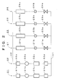
- Fig. 2 shows the refrigerant circuit comprising the showcases 21 to 24 and the refrigerating machines 31 and 32 shown in Fig. 1 .
- the refrigerating machines 31 and 32 and the showcases 21 to 24 are connected to the refrigerant pipes 41, 42 in parallel.
- the refrigerant circuit of the refrigerating machine 31 includes an accumulator 31a, a compressor 31b, a condenser 31c and a receiver 31d.
- the accumulator 31a executes gas-liquid separation on the gas-phase refrigerant supplied from the showcases 21 to 24, and supplies only the gas-phase refrigerant to the compressor 31b.
- the compressor 31b is driven by a motor (not shown) to compress the gas-phase refrigerant supplied from the accumulator 31a, and supplies the compressed refrigerant as high-temperature and high-pressure refrigerant to the condenser 31c.
- the condenser 31c condenses the gas-phase refrigerant supplied from the compressor 31b by heat radiation, and supplies the condensed refrigerant as liquid-phase refrigerant to the receiver 31d.
- the receiver 31d temporarily stocks the liquid-phase refrigerant supplied from the condenser 31c, and then supplies the liquid-phase refrigerant through the refrigerant pipe 41 to the showcases 21 to 24.
- the refrigerating machine 32 has the same construction as the refrigerating machine 31, and thus the description thereof is omitted.
- the showcase 21 has an electromagnetic valve 21a, an expansion valve 21b and a cooling device 21c.
- the electromagnetic valve 21a is a valve which is turned on or off to allow or prohibit flow of liquid-phase refrigerant into the showcase 21.
- the expansion valve 21b is a valve for expanding and vaporizing the liquid-phase refrigerant supplied through the electromagnetic valve 21a.
- the cooling device 21c is supplied with refrigerant expanded by the expansion valve 21b, and the expanded refrigerant is heat-exchanged with air in the showcase. Through this heat-exchange, the refrigerant is vaporized while absorbing vaporization heat from the air. Therefore, the temperature in the showcase is reduced to a set temperature.
- Each of the showcases 22 to 24 has the same construction as the showcase 21, and thus the description thereof is omitted.
- the electromagnetic valves 21a to 24a are provided to the showcases 21 to 24, respectively.
- only one electromagnetic valve may be provided so that the refrigerant pipe 41 is connected to the inlet side of the electromagnetic valve and the expansion valves 21b to 24b are connected to the outlet side of the electromagnetic valve.
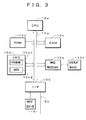
- Fig. 3 is a block diagram showing an example of the electrical construction of the controller 10 shown in Fig. 1 .
- the controller 10 has CPU (Central Processing Unit) 10a, ROM (Read Only Memory) 10b, RAM (Random Access Memory) 10c, HDD (Hard Disk Drive0 10d, an image processor 10e, a display device 10f, a bus 10g, I/F (Interface) 10h and an input device 10i.
- CPU 10a executes various kinds of operation processing in accordance with programs stored in ROM 10b and HDD 100d, and also controls the showcases 21 to 24 and the refrigerating machines 31 and 32.
- ROM 10b stores a basic program to be executed by CPU 10a.
- RAM 10c is used as a work area when CPU 10a executes the programs.
- HDD 10d is a storage device for reading/writing information from/into a hard disk, and a program 10d1 and data 10d2 are stored in HDD 10d in the example of Fig. 3 .
- the program 10d1 has OS and a program in which the procedure for executing processing described later is described.
- the data 10d2 has information to be referred to in processing described later.
- the image processor 10e executes drawing processing on the basis of a drawing instruction supplied from CPU 10a, converts an obtained image to a video signal and supplies the video signal to the display device 10f.
- the display device 10f comprises LCD (Liquid Crystal Display) or the like, and displays a video signal supplied from the image processor 10e on a display unit.
- CPU 10a, Rom 10b, RAM 10c, HDD 10d, the image processor 10e and I/F 10h are mutually connected to one another through a bus 10g, and information can be communicated among them.
- I/F 10h are connected to the showcases 21 to 24 and the refrigerating machines 31 and 32 through the communication line 50, and executes conversion of the protocol, etc. when information are transmitted/received to/from them.
- an input device 10i is connected to I/F 10h, and when a manager operates the input device 10i, information output from the input device 10i is supplied through I/F 10h to CPU 10.
- a system manager operates the input device 10i of the controller 10 to set the inside temperature of each of the showcases 21 to 24 in accordance with goods to be put on show, and also executes settings concerning a defrost operation of the showcases 21 to 24. Specifically, the setting of the inside temperature is executed in accordance with the types of goods (for example, meats, fishes, dairy products, etc. to be put on show in each showcase.
- grouping when the defrost operation is executed is set.
- the showcases 21 and 22 are set as belonging to a defrost group A
- the showcases 23 and 24 are set as belonging to a defrost group B.
- the grouping is executed so that showcases arranged to be adjacent to each other belong to the same group. Accordingly, air which is warmed through the defrost operation in some showcase can be prevented from flowing into other adjacent showcases and thus increasing the inside temperature of the adjacent showcases concerned.
- the manager operates the input device 10i of the controller 10 to input a time at which the defrost operation of each defrost group is started (hereinafter referred to as "defrost operation start time").
- defrost operation start time a time at which the defrost operation of each defrost group is started.
- the input defrost operation start time is supplied to the showcases 21 to 24 through the communication line 50, and a control unit (not shown) which is provided to each of the showcases 21 to 24 and controls the overall operation (containing the defrost operation) of the corresponding showcase obtains and stores the defrost operation start time concerned.
- each of the showcases 21 to 24 compares a time notified from a timer (not shown) with the stored defrost operation start time, and if these times are coincident with each other, the processing shown in Fig. 4 is executed.
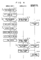
- Fig. 4 shows an example of the processing executed in the showcases 21 and 22, the controller 10 and the refrigerating machines 31 and 32 when the defrost operation is executed in the defrost group A.
- CPU of each of the showcases 21 and 22 belonging to the defrost group A determines in step S10 whether the defrost operation start time set in the controller 10 has come, and if the defrost operation start time has come (step S10: Yes), the processing goes to step S11. If not so (step S10; No), the same processing is repeated until the defrost operation start time has come.
- the timers of the showcases 21 and 22 are synchronized with each other, and the defrost operation start time is set to the same value in the showcases of the same group. Accordingly, when the defrost operation start time has come, "Yes" is determined in step S10, and the processing goes to step S11.
- step S11 the showcases 21 and 22 notify the start of the defrost operation to the controller 10 through the communication line 50. That is, each of the control units (not shown) of the showcases 21 and 22 transmits a notification indicating the start of the defrosting operation through the communication line 50 to the controller 10.
- CPU 10a receives the defrost operation starting notification from the respective control units through I/F 10h, and the processing goes to step S12, so that CPU 10a instructs the refrigerating machines 31 and 32 to reduce the output power thereof.
- CPU 10a instructs the refrigerating machines 31 and 32 so that the total decrease amount of the output power of the refrigerating machines 31 and 32 corresponds to the decrease amount of output power caused by the defrost operation executed in the defrost group A.
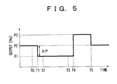
- the total output power of the refrigerating machines 31 and 32 at To is equal to P2
- the total output power p2 is reduced by ⁇ P and set to P1.
- the specific value of ⁇ P may be determined as follows. That is, the defrosting group A is made to actually execute the defrost operation, and the output power which is actually reduced through this defrost operation is measured and ⁇ P is set to this measurement value.
- the set temperature, the machine type, the type and amount of goods to be put on show, etc. are different from the defrost group A, and thus ⁇ P is required to be determined separately.
- the control of reducing the total output power by only ⁇ P is executed. For example, when a motor for driving the compressor 31b 932b) is driven with power supplied from an inverter, the rotational number of the motor is reduced by lowering the frequency of the inverter to reduce the output power. Furthermore, when the motor has no inverter, both or any one of the refrigerating machines 31 and 32 may be intermittently stopped to reduce the average output power. By executing the control as described above, the total output power of the refrigerating machines 31 and 32 is reduced by ⁇ P and set to P1 at the time T1.
- step S14 the processing of step S14 is executed, and it is determined whether a predetermined time elapses from the notification of the start of the defrost operation in step S11. If the predetermined time elapses (step S14; Yes), the processing goes to step S15. In the other cases (step S14; No), the same processing is repeated until the predetermined time elapses.
- the "predetermined time” in step S14 is different every system. Accordingly, an optimum value is determined every system and the determined optimum value is set as the "predetermined time".
- a time at which temperature increase at the inlets of the refrigerant machines 31, 32 at the start time of the defrost operation is lowest is determined.
- the predetermined time it is also required to pay attention to a delay time caused by the communication from the notification time of the start of the defrost operation till the arrival time of the output power reducing indication at the refrigerating machines 31, 32.
- the expansion valves 21b and 22b or the electromagnetic valves 21a and 22a are closed to interrupt the flow-in of refrigerant into the cooling devices 21c and 22c, and also air is blown to the cooling devices 21c, 22c to start an operation of removing frost adhering to the cooling devices 21c and 22c.
- the defrosting operation is started as described above, no refrigerant is circulated through the showcases 21 and 22, and thus it is required to reduce the output power of the refrigerating machines 31 and 32.
- the total output power of the refrigerating machines 31 and 32 is reduced prior to the start of the defrost operation, and thus needless refrigerant can be prevented frombeing supplied to the showcases 21 to 24, and thus the output power of the refrigerating machines 31 and 32 can be prevented from being needlessly wasted.
- step S16 the showcases 21 and 22 determine whether the defrost operation is finished or not. If it is finished (step S16; Yes), the processing goes to step S17. In the other cases (step S16; No), the same processing is repeated until the defrost is finished. More specifically, in the showcases 21 and 22, the temperature of each of the cooling devices 21c, 22c is detected by a sensor, and when the detected temperature is equal to a predetermined temperature or more, it is determined that the defrost is finished, and the processing goes to step S17. The end of the defrost operation is determined every showcase because the set temperature is different or the amount (number) of goods which are put on show in each showcase is different between the showcases.
- step S17 the showcase which determines the end of the defrost finishes the defrost operation.
- step S18 the showcase in which the defrost is finished notifies the controller 10 of the end of the defrost operation and the start of a cooling operation of reducing the inside temperature of the showcase to a set temperature.
- CPU 10a receives the cooling start notification through I/F 10h.
- CPU 10a recognizes the reception of the cooling start notification, and transmits an output power increasing instruction to the refrigerating machines 31 and 32 through I/F 10h and the communication line 50 so that the output power of the refrigerating machines 31 and 32 is increased in step S19.
- step S20 the refrigerating machines 31, 32 increases the frequency of the inverter and thus increases the rotational numbers of the compressors 31b and 32b.
- the amounts of the liquid-phase refrigerant discharged from the refrigerating machines 31 and 32 increase.
- the increase amounts are set so as to maximize the output power of the refrigerating machines 31 and 32.
- the inside temperature of each showcase is increased by the defrost operation, and thus it is necessary to rapidly reduce the inside temperature of each showcase.
- step S21 the showcase in which defrost is finished starts to cool the inside of the showcase concerned. That is, the showcase in which defrost is finished executes the processing of setting the expansion valve or the electromagnetic valve to an open state so that refrigerant is led to the cooling device. As a result, re-cooling of the inside of the showcase is started in the showcase in which defrost has been completed.
- step S22 CPU 10a determines whether a predetermined time elapses from the instruction of increasing the output power. If the predetermined time elapses (step S22; Yes), the processing goes to step S22, and if not so (step S22; No), the same processing is repeated until the predetermined time elapses.
- the "predetermined time” in step S22 may be set to a time required till the temperature of each of the showcases 21, 22 is returned to the set temperature from the start of cooling. As described above, the "predetermined time” may be calculated by actual measurement.
- step S23 CPU 10a instructs the refrigerating machines 31, 32 to output the stationary output power. That is, CPU 10a transmits a control signal to each of the refrigerating machines 31, 32 through I/F 10h and the communication line 50 to instruct the refrigerating machines 31, 32 so that the output power thereof is returned to the stationary output power.
- step S24 the frequencies of the refrigerating machines 31, 32 are returned to the frequencies under the stationary state, and thus the total output power of the refrigerating machines 31, 32 is returned to P2 which is the total output power under the stationary state.
- the stationary output power means the output power of the refrigeratingmachines 31, 32 when the refrigerating system is under the stationary state.
- the stationary state varies in accordance with the environment in which the showcases 21 to 24 are disposed, the type and number of goods put on show in each showcase, the set temperature, etc., and thus it is not set to a fixed state at all times. Accordingly, an output value under a state before the defrost operation is started may be utilized as a stationary state value.
- the defrost group A executes the defrost operation.
- the defrost group B executes the defrost operation, the same processing is executed as in the case of the defrost group A.
- the controller 10 instructs the refrigerating machines 31 and 32 to reduce the output power thereof when some showcase executes the defrost operation, and the refrigerating machines 31 and 32 reduce the output power in response to the instruction from the controller 10. Accordingly, before the defrost operation is executed or substantially in synchronization with the defrost operation, the output power of each of the refrigerating machines 31 and 32 (or the total output power of the refrigerating machines 31 and 32) can be reduced. Therefore, refrigerant can be prevented from being excessively supplied and thus the operation efficiency can be enhanced.
- the output power of each of the refrigerating machines 31 and 32 is increased. Therefore, the temperature of the showcase in which the defrost operation is finished can be rapidly reduced. Accordingly, the temperature of goods put on show in the showcase can be prevented from increasing. Furthermore, when the output power is increased and then the temperature of the showcase is reduced till the vicinity of the set temperature, the refrigerating machines 31 and 32 returns to the stationary operation. Accordingly, when the temperature of the inside of the showcase decreases till the set temperature, the power loss can be reduced by reducing the output power.
- the decrease of the output power of each refrigerating machine 31, 32 (or the decrease of the total output power of the refrigerating machines 31 and 32) is measured and stored in HDD 10d every defrost group in advance, and when the defrost operation is started, the output power of each of the refrigerating machines 31, 32 (the total output power of the refrigerating machines 31 and 32) is reduced on the basis of the information stored in HDD 10d. Therefore, when the defrost operation is executed, the output power of the refrigerating machine(s) can be rapidly reduced to a proper value.
- the refrigerating system contains the four showcases and the two refrigerating machines.
- the number of the showcases may be set to three or less or five or more, and the number of the refrigerating machines may be set to one or three or more.
- Each defrost group comprises two showcases, and thus two defrost groups are provided.
- the number of showcases constituting each defrost group may be set to one or three or more, and thus one or three or more defrost groups may be provided.
- the respective defrost groups may have different numbers of showcases.
- each of the refrigerating machines 31 and 32 controls the frequency of the inverter to change the output power.
- a predetermined refrigerating machine out of plural refrigerating machines may be stopped or intermittently operated to change the total output of the refrigerating machines.
- the controller 10 when the controller 10 receives the defrost operation start notification from the showcases 21 to 24, the control instructs the reduction of the output power.
- the defrost operation start time of each defrost group may be stored in HDD 10d of the controller 10 in advance.
- the controller 10 compares the stored defrost operation start time with the present time, and detects the start of the defrost operation to instruct the reduction of the output power.
- the controller instructs the reduction of the output power at a time which is earlier than the defrost operation start time by a predetermined time, it would be unnecessary for the showcase side to determine whether the predetermined time elapses or not (step S14).
- the controller 10 may adjust the predetermined time on the basis of the past control, whereby the predetermined time is optimized and the operation efficiency can be further enhanced.
- the controller 10 instructs the output power amount (AP in Fig. 5 ) to be reduced.
- the controller 10 may notify only information for specifying the defrost group in which the defrost operation is started.
- the refrigerating machines reduce the output power on the basis of the notified information for specifying the defrost group. For example, when it is notified from the controller 10 that the defrost group A starts the defrost operation, the refrigerating machines 31, 32 reduce the total output power by only ⁇ PA. When it is notified from the controller 10 that the defrost group B starts the defrost operation, the refrigerating machines 31, 32 reduces the total output power by only ⁇ PB.
- the controller 10 increases the output power of each of the refrigerating machines 31, 32 (or the total output power of the refrigerating machines 31, 32) to the maximum level.
- the output power may be stepwise increased in accordance with the number or type of showcases in which the defrost operation is finished. For example, when the showcase 21 finishes the defrost operation during the defrost operation of the defrost group A, the output power is increased by only the amount corresponding to the showcase 21, and when the showcase 22 finishes the defrost operation, the output power is increased by only the amount corresponding to the showcase 22.
- the output power can be increased by only an optimum amount in accordance with the type of the showcase, the set temperature, the amount (number) of goods put on show in the showcase, etc. , and thus the operation efficiency can be enhanced.
- the stationary operation when the operation is returned to the stationary operation after the output power is increased, it is determined on the basis of the judgment as to whether a predetermined time elapses or not in step S22.
- the stationary operation may be restored on the basis of the inside temperature of the showcase in which the defrost operation is finished or the like. Specifically, when the inside temperature of the showcase 21 is first restored to the set temperature, the output power is reduced by the corresponding amount, and then when the inside temperature of the showcase 22 is restored to the set temperature, the output power may be reduced by the corresponding amount.
- each of the refrigerating machines 31 and 32 when the defrost operation is started, each of the refrigerating machines 31 and 32 reduces the output power thereof so that the total output power of the refrigerating machines 31 and 32 is reduced by a predetermined amount.
- only any one of the refrigerating machines 31 and 32 may reduce the output power thereof so that the total output power of the refrigerating machines 31 and 32 is reduced by a predetermined amount.
- the controller 10 instructs the refrigerating machines to reduce the total output power thereof.
- the refrigerating machines 31, 32 reduces the output power thereof by themselves. Accordingly, even when each of the showcases and the refrigerating machines is exchanged by a new one or another type one, or even when a new showcase and/or a new refrigerating machine is added, the same effect as described above can be obtained by merely interposing the controller 10 between the showcase and the refrigerating machine insofar as each of the showcases and the refrigerating machines has the function as shown in Fig. 4 .
Landscapes
- Engineering & Computer Science (AREA)
- Chemical & Material Sciences (AREA)
- Combustion & Propulsion (AREA)
- Physics & Mathematics (AREA)
- Mechanical Engineering (AREA)
- Thermal Sciences (AREA)
- General Engineering & Computer Science (AREA)
- Defrosting Systems (AREA)
- Devices That Are Associated With Refrigeration Equipment (AREA)
Abstract
Description
- The present invention relates to a controller and a control method for a refrigerating system.
-
JP-A-2004-257666 - The present invention has been implemented in view of the foregoing situation, and has an object to provide a controller and a control method that can efficiently execute a defrost operation in a refrigerating system.
- In order to attain the above object, according to an aspect of the present invention, a controller for a refrigerating system including at least refrigerating machines and at least one showcase connected to the refrigerating machine through a refrigerant pipe, comprises: a defrost showcase detecting unit for detecting, on the basis of a defrost operation indicating information, a showcase that is about to execute a defrost operation; an output-power decrease instructing unit for instructing at least one of the refrigerating machines to reduce the output power of the at least one refrigerating machine to a value lower than stationary output power of the at least one refrigerating machine concerned when the showcase concerned executes the defrost operation; and an output-power increase instruction unit for instructing the at least one refrigerating machine to increase the output power of the at least one refrigeratingmachine to a value higher than the stationary output power of the at least one refrigerating machine when the defrost operation is finished.
- The above controller may further comprise a detecting unit for detecting as the defrost operation indicating information a notification that is transmitted from the showcase concerned when the showcase concerned is about to execute the defrost operation.
- The above controller may further comprise a storage unit for storing a defrost operation start time of the showcase concerned, a comparing unit for comparing the defrost operation start time stored in the storage unit with present time, and a step of instructing the at least one refrigerating machine to increase the output power thereof when the defrost operation start time is coincident with the present time.
- In the above controller, the output-power increase instruction unit may reduce the output power of the at least one refrigerating machine to the stationary state when the inside temperature of the showcase concerned is restored to a neighborhood of set temperature after the output power of the at least one refrigerating machine is increased.
- The above controller may further comprise a storage unit for pre-storing a decrease amount of the output power of the at least one refrigerating machine which is measured every refrigeratingmachine, and the output-power decrease instructing unit instructs the at least one refrigerating machine to reduce the output power thereof on the basis of the decrease amount of the output power pre-stored in the storage unit when the defrost operation is started.
- In the above controller, when plural showcases start the defrost operation in synchronization with one another, the output-power increase instructing unit instructs the at least one refrigerating machine to stepwise increase the output power thereof in accordance with the number of showcases in which the defrosting operation has been finished.
- According to a second aspect of the present invention, a control method for a refrigerating system including at least refrigerating machines and at least one showcase connected to the refrigerating machine through a refrigerant pipe, comprises: a defrost showcase detecting step for detecting, on the basis of a defrost operation indicating information, a showcase that is about to execute a defrost operation; an output-power decrease instructing step for instructing at least one of the refrigerating machines to reduce the output power of the at least one refrigerating machine when the showcase concerned executes the defrost operation; and an output-power increase instruction step for instructing the at least one refrigerating machine to increase the output power of the at least one refrigerating machine when the showcase concerned finishes the defrost operation.
- The above control method may further comprise a detecting step for detecting as the defrost operation indicating information a notification that is transmitted from the showcase concerned when the showcase concerned is about to execute the defrost operation.
- The above control method may further comprise a storage step for storing a defrost operation start time of the showcase concerned, a comparing step for comparing the defrost operation start time stored in the storage unit with present time and a instructing step of instructing the at least one refrigerating machine to increase the output power thereof when the defrost operation start time is coincident with the present time.
- According to the controller and the control method for the refrigerating system of the present invention, when the defrost operation is started, the output power of the refrigerating machine(s) is reduced, and when the defrost operation is finished, the output power of the refrigerating machine (s) is increased. Accordingly, the defrost operation of the refrigerating machine(s) can be efficiently performed.
- Furthermore, when the output power of the refrigerating machine is increased at the end time of the defrost operation and then the inside temperature of the showcase is restored to a neighborhood of the set temperature, the output power of the refrigerating machine is reduced till the stationary state. Accordingly, when the defrost operation is finished and the inside temperature of the showcase approaches to the set temperature, the output power of the refrigerating machine can be rapidly restored to the stationary state, whereby power consumption can be suppressed.
- According to the present invention, the output power of the refrigerating machine when the defrost operation is started is reduced on the basis of the storage value. Therefore, the control can be performed on the basis of the stored actual measurement value, and thus the power consumption can be suppressed by the optimum control.
- Furthermore,according to the presentinvention,the output power of the refrigerating machine is increased in accordance with the number of showcases in which the defrost operation is finished. Therefore, even when the required time of the defrost operation is different every showcase, the output power of the refrigerating machine can be stepwise increased, whereby the optimum control can be performed and the power consumption can be suppressed.
-
-
Fig. 1 is a diagram showing the construction of a refrigerating system according to an embodiment of the present invention; -
Fig. 2 is a diagram showing a refrigerant circuit of the refrigerating system shown inFig. 1 ; -
Fig. 3 is a diagram showing an example of the detailed construction of a controller shown inFig. 1 ; -
Fig. 4 is a flowchart showing the operation of the refrigerating system shown inFig. 1 ; and -
Fig. 5 is a diagram showing time-variation of the output of a refrigerating machine of the refrigerating system shown inFig. 1 . - Preferred embodiments according to the present invention will be described hereunder with reference to the accompanying drawings.
-
Fig. 1 is a diagram showing an example of the construction of an embodiment of the present invention. As shown inFig. 1 , a refrigerating system according to the embodiment is disposed in a store such as a supermarket, a convenience store or the like to keep goods cold or freeze goods. The refrigerating system contains acontroller 10 for controlling the overall operation of the refrigerating system, one or more showcases (in this embodiment, fourshowcases 21 to 24) in which goods are kept in cold storage or frozen, one or more refrigerating machines (in this embodiment, two refrigeratingmachines 31, 32), one or more refrigerant pipes (in this embodiment, tworefrigerant pipes 41, 42) through which the showcases and the refrigerating machines are connected to one another, and acommunication line 50 through which data communications are executed among theshowcases 21 to 24, the refrigeratingmachines controller 10. In the present invention, the numbers of the showcases and the refrigerating machines are not limited to the following embodiment, and any number may be adopted according to the situation. - Here, as described later, the
controller 10 comprises a general-purpose computer such as a personal computer or the like, and controls theshowcases 21 to 24 and the refrigeratingmachines showcases 21 to 24 are disposed in a store such a supermarket, a convenience store or the like, and goods are placed on show in these showcases. Theshowcases 21 to 24 are connected to each of therefrigerant pipes machines refrigerant pipe 41 into each showcase, evaporated in a cooling device (described later) provided to the showcase and heat-exchanged with air in the showcase, thereby reducing the temperature of the inside of the showcase. Gas-phase refrigerant vaporized in the cooling device is returned to the refrigeratingmachines refrigerant pipe 42. Theshowcases 21 to 24 are connected to thecontroller 10 through thecommunication line 50, and communicate information with thecontroller 10. - Each of the
refrigeratingmachines showcases 21 to 24 is withdrawn through therefrigerant pipe 42 into each refrigerating machine, compressed in the compressor and then condensed in the condenser to be changed to liquid-phase refrigerant again. The liquid-phase refrigerant concerned is supplied through therefrigerant pipe 41 to theshowcases 21 to 24. Furthermore, the refrigeratingmachines controller 10 through thecommunication line 50, and receives/transmits information from/to thecontroller 10 through thecommunication line 50. -
Fig. 2 shows the refrigerant circuit comprising theshowcases 21 to 24 and the refrigeratingmachines Fig. 1 . As shown inFig. 2 , the refrigeratingmachines showcases 21 to 24 are connected to therefrigerant pipes machine 31 includes an accumulator 31a, a compressor 31b, acondenser 31c and a receiver 31d. Here, the accumulator 31a executes gas-liquid separation on the gas-phase refrigerant supplied from theshowcases 21 to 24, and supplies only the gas-phase refrigerant to the compressor 31b. The compressor 31b is driven by a motor (not shown) to compress the gas-phase refrigerant supplied from the accumulator 31a, and supplies the compressed refrigerant as high-temperature and high-pressure refrigerant to thecondenser 31c. Thecondenser 31c condenses the gas-phase refrigerant supplied from the compressor 31b by heat radiation, and supplies the condensed refrigerant as liquid-phase refrigerant to the receiver 31d. The receiver 31d temporarily stocks the liquid-phase refrigerant supplied from thecondenser 31c, and then supplies the liquid-phase refrigerant through therefrigerant pipe 41 to theshowcases 21 to 24. The refrigeratingmachine 32 has the same construction as the refrigeratingmachine 31, and thus the description thereof is omitted. - The
showcase 21 has an electromagnetic valve 21a, an expansion valve 21b and a cooling device 21c. Here, the electromagnetic valve 21a is a valve which is turned on or off to allow or prohibit flow of liquid-phase refrigerant into theshowcase 21. The expansion valve 21b is a valve for expanding and vaporizing the liquid-phase refrigerant supplied through the electromagnetic valve 21a. The cooling device 21c is supplied with refrigerant expanded by the expansion valve 21b, and the expanded refrigerant is heat-exchanged with air in the showcase. Through this heat-exchange, the refrigerant is vaporized while absorbing vaporization heat from the air. Therefore, the temperature in the showcase is reduced to a set temperature. Each of theshowcases 22 to 24 has the same construction as theshowcase 21, and thus the description thereof is omitted. In the example ofFig. 2 , the electromagnetic valves 21a to 24a are provided to theshowcases 21 to 24, respectively. However, only one electromagnetic valve may be provided so that therefrigerant pipe 41 is connected to the inlet side of the electromagnetic valve and the expansion valves 21b to 24b are connected to the outlet side of the electromagnetic valve. -
Fig. 3 is a block diagram showing an example of the electrical construction of thecontroller 10 shown inFig. 1 . - As shown in
Fig. 3 , thecontroller 10 has CPU (Central Processing Unit) 10a, ROM (Read Only Memory) 10b, RAM (Random Access Memory) 10c, HDD (Hard Disk Drive0 10d, an image processor 10e, a display device 10f, a bus 10g, I/F (Interface) 10h and an input device 10i. Here, CPU 10a executes various kinds of operation processing in accordance with programs stored in ROM 10b and HDD 100d, and also controls theshowcases 21 to 24 and the refrigeratingmachines HDD 10d is a storage device for reading/writing information from/into a hard disk, and a program 10d1 and data 10d2 are stored inHDD 10d in the example ofFig. 3 . The program 10d1 has OS and a program in which the procedure for executing processing described later is described. The data 10d2 has information to be referred to in processing described later. The image processor 10e executes drawing processing on the basis of a drawing instruction supplied from CPU 10a, converts an obtained image to a video signal and supplies the video signal to the display device 10f. For example, the display device 10f comprises LCD (Liquid Crystal Display) or the like, and displays a video signal supplied from the image processor 10e on a display unit. CPU 10a, Rom 10b, RAM 10c,HDD 10d, the image processor 10e and I/F 10h are mutually connected to one another through a bus 10g, and information can be communicated among them. I/F 10h are connected to theshowcases 21 to 24 and the refrigeratingmachines communication line 50, and executes conversion of the protocol, etc. when information are transmitted/received to/from them. Furthermore, an input device 10i is connected to I/F 10h, and when a manager operates the input device 10i, information output from the input device 10i is supplied through I/F 10h toCPU 10. - Next, the operation of this embodiment will be described.
- When installation of the
controller 10, theshowcases 21 to 24 and the refrigeratingmachines controller 10 to set the inside temperature of each of theshowcases 21 to 24 in accordance with goods to be put on show, and also executes settings concerning a defrost operation of theshowcases 21 to 24. Specifically, the setting of the inside temperature is executed in accordance with the types of goods (for example, meats, fishes, dairy products, etc. to be put on show in each showcase. - Furthermore, with respect to the defrost operation, grouping when the defrost operation is executed is set. In the example of
Fig. 1 , theshowcases showcases - Still furthermore, the manager operates the input device 10i of the
controller 10 to input a time at which the defrost operation of each defrost group is started (hereinafter referred to as "defrost operation start time"). As a result, the input defrost operation start time is supplied to theshowcases 21 to 24 through thecommunication line 50, and a control unit (not shown) which is provided to each of theshowcases 21 to 24 and controls the overall operation (containing the defrost operation) of the corresponding showcase obtains and stores the defrost operation start time concerned. When the group to be defrosted and the defrost operation start time are set as described above, each of theshowcases 21 to 24 compares a time notified from a timer (not shown) with the stored defrost operation start time, and if these times are coincident with each other, the processing shown inFig. 4 is executed. -
Fig. 4 shows an example of the processing executed in theshowcases controller 10 and the refrigeratingmachines showcases controller 10 has come, and if the defrost operation start time has come (step S10: Yes), the processing goes to step S11. If not so (step S10; No), the same processing is repeated until the defrost operation start time has come. The timers of theshowcases - In step S11, the
showcases controller 10 through thecommunication line 50. That is, each of the control units (not shown) of theshowcases communication line 50 to thecontroller 10. As a result, in thecontroller 10, CPU 10a receives the defrost operation starting notification from the respective control units through I/F 10h, and the processing goes to step S12, so that CPU 10a instructs the refrigeratingmachines machines machines Fig. 5 , when the total output power of the refrigeratingmachines - In the
refrigerating machines controller 10, the control of reducing the total output power by only ΔP is executed. For example, when a motor for driving the compressor 31b 932b) is driven with power supplied from an inverter, the rotational number of the motor is reduced by lowering the frequency of the inverter to reduce the output power. Furthermore, when the motor has no inverter, both or any one of the refrigeratingmachines machines - At this time, in the
showcases machines refrigerant machines machines - When the defrost operation is started in step S15 in the
showcases showcases machines machines showcases 21 to 24, and thus the output power of the refrigeratingmachines - In step S16, the
showcases showcases - In step S17, the showcase which determines the end of the defrost finishes the defrost operation. In step S18, the showcase in which the defrost is finished notifies the
controller 10 of the end of the defrost operation and the start of a cooling operation of reducing the inside temperature of the showcase to a set temperature. As a result, in thecontroller 10, CPU 10a receives the cooling start notification through I/F 10h. CPU 10a recognizes the reception of the cooling start notification, and transmits an output power increasing instruction to therefrigerating machines communication line 50 so that the output power of the refrigeratingmachines machines machines machines - The above operation will be more specifically described.
- As shown in
Fig. 5 , when defrost is finished at a time T3, the total output power of the refrigeratingmachines - In step S22, CPU 10a determines whether a predetermined time elapses from the instruction of increasing the output power. If the predetermined time elapses (step S22; Yes), the processing goes to step S22, and if not so (step S22; No), the same processing is repeated until the predetermined time elapses. The "predetermined time" in step S22 may be set to a time required till the temperature of each of the
showcases - In step S23, CPU 10a instructs the refrigerating
machines machines communication line 50 to instruct therefrigerating machines machines machines refrigeratingmachines showcases 21 to 24 are disposed, the type and number of goods put on show in each showcase, the set temperature, etc., and thus it is not set to a fixed state at all times. Accordingly, an output value under a state before the defrost operation is started may be utilized as a stationary state value. - In the foregoing description, the defrost group A executes the defrost operation. However, when the defrost group B executes the defrost operation, the same processing is executed as in the case of the defrost group A.
- As described above, according to the embodiment of the present invention, the
controller 10 instructs the refrigeratingmachines machines controller 10. Accordingly, before the defrost operation is executed or substantially in synchronization with the defrost operation, the output power of each of the refrigeratingmachines 31 and 32 (or the total output power of the refrigeratingmachines 31 and 32) can be reduced. Therefore, refrigerant can be prevented from being excessively supplied and thus the operation efficiency can be enhanced. - Furthermore, according to this embodiment, when the defrost operation is finished, the output power of each of the refrigerating
machines machines - Still furthermore, according to this embodiment, the decrease of the output power of each refrigerating
machine 31, 32 (or the decrease of the total output power of the refrigeratingmachines 31 and 32) is measured and stored inHDD 10d every defrost group in advance, and when the defrost operation is started, the output power of each of the refrigeratingmachines 31, 32 (the total output power of the refrigeratingmachines 31 and 32) is reduced on the basis of the information stored inHDD 10d. Therefore, when the defrost operation is executed, the output power of the refrigerating machine(s) can be rapidly reduced to a proper value. - The above embodiment is an example of the present invention, and any modification and any application may be performed without departing from the subject matter of the preset invention.
- For example, in the above embodiment, the refrigerating system contains the four showcases and the two refrigerating machines. However, the number of the showcases may be set to three or less or five or more, and the number of the refrigerating machines may be set to one or three or more. Each defrost group comprises two showcases, and thus two defrost groups are provided. However, the number of showcases constituting each defrost group may be set to one or three or more, and thus one or three or more defrost groups may be provided. Furthermore, the respective defrost groups may have different numbers of showcases.
- In the above embodiment, each of the refrigerating
machines - Furthermore, in the above embodiment, when the
controller 10 receives the defrost operation start notification from theshowcases 21 to 24, the control instructs the reduction of the output power. Alternatively, the defrost operation start time of each defrost group may be stored inHDD 10d of thecontroller 10 in advance. In this case, thecontroller 10 compares the stored defrost operation start time with the present time, and detects the start of the defrost operation to instruct the reduction of the output power. In this embodiment, if the controller instructs the reduction of the output power at a time which is earlier than the defrost operation start time by a predetermined time, it would be unnecessary for the showcase side to determine whether the predetermined time elapses or not (step S14). Furthermore, thecontroller 10 may adjust the predetermined time on the basis of the past control, whereby the predetermined time is optimized and the operation efficiency can be further enhanced. - In the above embodiment, the
controller 10 instructs the output power amount (AP inFig. 5 ) to be reduced. Alternatively, thecontroller 10 may notify only information for specifying the defrost group in which the defrost operation is started. In this case, the refrigerating machines reduce the output power on the basis of the notified information for specifying the defrost group. For example, when it is notified from thecontroller 10 that the defrost group A starts the defrost operation, the refrigeratingmachines controller 10 that the defrost group B starts the defrost operation, the refrigeratingmachines - Furthermore, in the above embodiment, when the defrost operation is finished in one showcase, the
controller 10 increases the output power of each of the refrigeratingmachines 31, 32 (or the total output power of the refrigeratingmachines 31, 32) to the maximum level. However, the output power (total output power) may be stepwise increased in accordance with the number or type of showcases in which the defrost operation is finished. For example, when theshowcase 21 finishes the defrost operation during the defrost operation of the defrost group A, the output power is increased by only the amount corresponding to theshowcase 21, and when theshowcase 22 finishes the defrost operation, the output power is increased by only the amount corresponding to theshowcase 22. According to this method, the output power can be increased by only an optimum amount in accordance with the type of the showcase, the set temperature, the amount (number) of goods put on show in the showcase, etc. , and thus the operation efficiency can be enhanced. - Furthermore, in the above embodiment, when the operation is returned to the stationary operation after the output power is increased, it is determined on the basis of the judgment as to whether a predetermined time elapses or not in step S22. However, the stationary operation may be restored on the basis of the inside temperature of the showcase in which the defrost operation is finished or the like. Specifically, when the inside temperature of the
showcase 21 is first restored to the set temperature, the output power is reduced by the corresponding amount, and then when the inside temperature of theshowcase 22 is restored to the set temperature, the output power may be reduced by the corresponding amount. - In the above-described embodiment, when the defrost operation is started, each of the refrigerating
machines machines machines machines - As described above, according to the present invention, on the basis of a notification indicating the start of the defrost operation from each showcase or from a timer, the
controller 10 instructs the refrigerating machines to reduce the total output power thereof. In response to the instruction from thecontroller 10, the refrigeratingmachines controller 10 between the showcase and the refrigerating machine insofar as each of the showcases and the refrigerating machines has the function as shown inFig. 4 .
Claims (9)
- A controller for a refrigerating system including at least refrigerating machines and at least one showcase connected to the refrigerating machine through a refrigerant pipe, comprising:a defrost showcase detecting unit for detecting, on the basis of a defrost operation indicating information, a showcase that is about to execute a defrost operation;an output-power decrease instructing unit for instructing at least one of the refrigerating machines to reduce the output power of the at least one refrigerating machine to a value lower than stationary output power of the at least one refrigerating machine concerned when the showcase concerned executes the defrost operation; andan output-power increase instruction unit for instructing the at least one refrigerating machine to increase the output power of the at least one refrigerating machine to a value higher than the stationary output power of the at least one refrigerating machine when the defrost operation is finished.
- The controller according to claim 1, further comprising a detecting unit for detecting as the defrost operation indicating information a notification that is transmitted from the showcase concerned when the showcase concerned is about to execute the defrost operation.
- The controller according to claim 1, further comprising a storage unit for storing a defrost operation start time of the showcase concerned, a comparing unit for comparing the defrost operation start time stored in the storage unit with present time, and a step of instructing the at least one refrigerating machine to increase the output power thereof when the defrost operation start time is coincident with the present time.
- The controller according to claim 1, wherein the output-power increase instruction unit reduces the output power of the at least one refrigerating machine to the stationary state when the inside temperature of the showcase concerned is restored to a neighborhood of set temperature after the output power of the at least one refrigerating machine is increased.
- The controller according to claim 1, further comprising a storage unit for pre-storing a decrease amount of the output power of the at least one refrigerating machine which is measured every refrigerating machine, and the output-power decrease instructing unit instructs the at least one refrigerating machine to reduce the output power thereof on the basis of the decrease amount of the output power pre-stored in the storage unit when the defrost operation is started.
- The controller according to claim 1, wherein when plural showcases start the defrost operation in synchronization with one another, the output-power increase instructing unit instructs the at least one refrigerating machine to stepwise increase the output power thereof in accordance with the number of showcases in which the defrosting operation has been finished.
- A control method for a refrigerating system including at least refrigerating machines and at least one showcase connected to the refrigerating machine through a refrigerant pipe, comprising:a defrost showcase detecting step for detecting, on the basis of a defrost operation indicating information, a showcase that is about to execute a defrost operation;an output-power decrease instructing step for instructing at least one of the refrigerating machines to reduce the output power of the at least one refrigerating machine when the showcase concerned executes the defrost operation; andan output-power increase instruction step for instructing the at least one refrigerating machine to increase the output power of the at least one refrigerating machine when the showcase concerned finishes the defrost operation.
- The control method according to claim 7, further comprising a detecting step for detecting as the defrost operation indicating information a notification that is transmitted from the showcase concerned when the showcase concerned is about to execute the defrost operation.
- The control method according to claim 7, further comprising a storage step for storing a defrost operation start time of the showcase concerned, a comparing step for comparing the defrost operation start time stored in the storage unit with present time and a instructing step of instructing the at least one refrigerating machine to increase the output power thereof when the defrost operation start time is coincident with the present time.
Applications Claiming Priority (1)
| Application Number | Priority Date | Filing Date | Title |
|---|---|---|---|
| JP2007316596A JP2009139028A (en) | 2007-12-07 | 2007-12-07 | Control device and control method of control device |
Publications (2)
| Publication Number | Publication Date |
|---|---|
| EP2068104A2 true EP2068104A2 (en) | 2009-06-10 |
| EP2068104A3 EP2068104A3 (en) | 2018-02-14 |
Family
ID=40468480
Family Applications (1)
| Application Number | Title | Priority Date | Filing Date |
|---|---|---|---|
| EP08021209.5A Withdrawn EP2068104A3 (en) | 2007-12-07 | 2008-12-05 | Controller and control method for refrigerating system |
Country Status (4)
| Country | Link |
|---|---|
| US (1) | US8397526B2 (en) |
| EP (1) | EP2068104A3 (en) |
| JP (1) | JP2009139028A (en) |
| CN (1) | CN101451784B (en) |
Families Citing this family (4)
| Publication number | Priority date | Publication date | Assignee | Title |
|---|---|---|---|---|
| CN102934036B (en) | 2010-02-15 | 2016-04-27 | 开利公司 | For estimating the system and method based on model of parameter in temperature controlled space and state |
| CN104930791B (en) * | 2014-03-21 | 2017-03-01 | 青月村燊股份有限公司 | A multifunctional freezer |
| JPWO2019082599A1 (en) * | 2017-10-25 | 2020-11-12 | ダイキン工業株式会社 | Refrigeration system |
| CN107940873B (en) * | 2017-11-17 | 2020-12-04 | 合肥美的电冰箱有限公司 | Defrost method, defrost system, computer readable storage medium and refrigeration apparatus |
Citations (1)
| Publication number | Priority date | Publication date | Assignee | Title |
|---|---|---|---|---|
| JP2004257666A (en) | 2003-02-26 | 2004-09-16 | Sanyo Electric Co Ltd | Controller of cooling system |
Family Cites Families (13)
| Publication number | Priority date | Publication date | Assignee | Title |
|---|---|---|---|---|
| US3905202A (en) * | 1974-01-08 | 1975-09-16 | Emhart Corp | Refrigeration system |
| US4151722A (en) * | 1975-08-04 | 1979-05-01 | Emhart Industries, Inc. | Automatic defrost control for refrigeration systems |
| JPS59185955A (en) * | 1983-04-08 | 1984-10-22 | 株式会社日立製作所 | Air conditioner combining air cooling and heating |
| SE451394B (en) * | 1986-01-31 | 1987-10-05 | Stal Refrigeration Ab | PROCEDURE FOR REGULATING A ROTATING COMPRESSOR |
| JPH04113183A (en) * | 1990-09-04 | 1992-04-14 | Sanyo Electric Co Ltd | Method for operating open show case |
| JPH04369354A (en) * | 1991-06-17 | 1992-12-22 | Mitsubishi Electric Corp | Refrigerator |
| JPH0571822A (en) * | 1991-09-10 | 1993-03-23 | Toshiba Corp | Air conditioner |
| JP3661337B2 (en) * | 1997-02-24 | 2005-06-15 | 富士電機リテイルシステムズ株式会社 | Showcase cooling system |
| US20040016253A1 (en) * | 2000-03-14 | 2004-01-29 | Hussmann Corporation | Refrigeration system and method of operating the same |
| JP2002243349A (en) * | 2001-02-16 | 2002-08-28 | Nippon Kentetsu Co Ltd | Defrosting control method for refrigerated showcase |
| US6629422B2 (en) * | 2001-06-07 | 2003-10-07 | Keith E. Wellman | Sequential defrosting of refrigerated display cases |
| JP4232945B2 (en) * | 2001-12-25 | 2009-03-04 | 中野冷機株式会社 | Showcase operation control method |
| US7337621B2 (en) * | 2004-01-07 | 2008-03-04 | Bbc Enterprises, Inc. | Optical frost sensor |
-
2007
- 2007-12-07 JP JP2007316596A patent/JP2009139028A/en active Pending
-
2008
- 2008-10-13 CN CN2008101701446A patent/CN101451784B/en not_active Expired - Fee Related
- 2008-12-05 EP EP08021209.5A patent/EP2068104A3/en not_active Withdrawn
- 2008-12-08 US US12/329,721 patent/US8397526B2/en not_active Expired - Fee Related
Patent Citations (1)
| Publication number | Priority date | Publication date | Assignee | Title |
|---|---|---|---|---|
| JP2004257666A (en) | 2003-02-26 | 2004-09-16 | Sanyo Electric Co Ltd | Controller of cooling system |
Also Published As
| Publication number | Publication date |
|---|---|
| CN101451784B (en) | 2011-01-12 |
| EP2068104A3 (en) | 2018-02-14 |
| JP2009139028A (en) | 2009-06-25 |
| US20090145144A1 (en) | 2009-06-11 |
| US8397526B2 (en) | 2013-03-19 |
| CN101451784A (en) | 2009-06-10 |
Similar Documents
| Publication | Publication Date | Title |
|---|---|---|
| EP2217872B1 (en) | Control method of refrigerator | |
| CN102472541B (en) | Apparatus for managing operation of freezing machine | |
| EP2446200B1 (en) | Low ambient operating procedure for cooling systems with high efficiency condensers | |
| EP3224554B1 (en) | Systems and methods for free and positive defrost | |
| JP2009210161A (en) | Equipment control system, control device, and control program | |
| CN108826820B (en) | Refrigeration method of multi-temperature control refrigeration house and refrigeration system of multi-temperature control refrigeration house | |
| US8397526B2 (en) | Controller and control method for refrigerating system | |
| US20040107709A1 (en) | Method for operating compressors of air conditioner | |
| JP2007060848A (en) | Apparatus and method for controlling electric energy and its program | |
| CN103216983B (en) | Cooling system | |
| JP2019078444A (en) | Cooling box | |
| KR102459591B1 (en) | Control Method of Air Conditioner | |
| JP5980002B2 (en) | Refrigeration / refrigeration system | |
| WO2018179366A1 (en) | Refrigeration cycle system and communication traffic adjustment method | |
| JP2013096589A (en) | Store centralized control device and method of measuring degree of influence of air conditioner on showcase | |
| JPH10122608A (en) | Ice heat storage device for freezing / refrigeration equipment and control method thereof | |
| JP3191561B2 (en) | Vending machine power saving device | |
| JP5914815B2 (en) | Control system | |
| JP7856914B2 (en) | Remote control devices, refrigeration systems | |
| JP6011290B2 (en) | Refrigeration system | |
| JP5906944B2 (en) | Demand control apparatus and demand control method | |
| CN110906670A (en) | Quick-freezing control method for reducing food freezing damage and quick-freezing refrigerator | |
| JP2002081713A (en) | Refrigeration equipment control device | |
| JP2012255566A (en) | Control device of refrigeration equipment | |
| JP4476948B2 (en) | Refrigeration apparatus and control method of refrigeration apparatus |
Legal Events
| Date | Code | Title | Description |
|---|---|---|---|
| PUAI | Public reference made under article 153(3) epc to a published international application that has entered the european phase |
Free format text: ORIGINAL CODE: 0009012 |
|
| AK | Designated contracting states |
Kind code of ref document: A2 Designated state(s): AT BE BG CH CY CZ DE DK EE ES FI FR GB GR HR HU IE IS IT LI LT LU LV MC MT NL NO PL PT RO SE SI SK TR |
|
| AX | Request for extension of the european patent |
Extension state: AL BA MK RS |
|
| PUAL | Search report despatched |
Free format text: ORIGINAL CODE: 0009013 |
|
| AK | Designated contracting states |
Kind code of ref document: A3 Designated state(s): AT BE BG CH CY CZ DE DK EE ES FI FR GB GR HR HU IE IS IT LI LT LU LV MC MT NL NO PL PT RO SE SI SK TR |
|
| AX | Request for extension of the european patent |
Extension state: AL BA MK RS |
|
| RIC1 | Information provided on ipc code assigned before grant |
Ipc: F25D 21/00 20060101AFI20180111BHEP |
|
| STAA | Information on the status of an ep patent application or granted ep patent |
Free format text: STATUS: THE APPLICATION HAS BEEN PUBLISHED |
|
| AKY | No designation fees paid | ||
| AXX | Extension fees paid |
Extension state: RS Extension state: BA Extension state: MK Extension state: AL |
|
| REG | Reference to a national code |
Ref country code: DE Ref legal event code: R108 |
|
| STAA | Information on the status of an ep patent application or granted ep patent |
Free format text: STATUS: THE APPLICATION IS DEEMED TO BE WITHDRAWN |
|
| 18D | Application deemed to be withdrawn |
Effective date: 20180815 |