EP2068024A2 - Joint homocinétique fixe avec chemins de roulements de forme d'entonnoir differentes - Google Patents
Joint homocinétique fixe avec chemins de roulements de forme d'entonnoir differentes Download PDFInfo
- Publication number
- EP2068024A2 EP2068024A2 EP08169288A EP08169288A EP2068024A2 EP 2068024 A2 EP2068024 A2 EP 2068024A2 EP 08169288 A EP08169288 A EP 08169288A EP 08169288 A EP08169288 A EP 08169288A EP 2068024 A2 EP2068024 A2 EP 2068024A2
- Authority
- EP
- European Patent Office
- Prior art keywords
- group
- ball tracks
- member ball
- funnels
- longitudinal axis
- Prior art date
- Legal status (The legal status is an assumption and is not a legal conclusion. Google has not performed a legal analysis and makes no representation as to the accuracy of the status listed.)
- Granted
Links
- 230000007935 neutral effect Effects 0.000 description 2
- 230000008878 coupling Effects 0.000 description 1
- 238000010168 coupling process Methods 0.000 description 1
- 238000005859 coupling reaction Methods 0.000 description 1
- 230000001419 dependent effect Effects 0.000 description 1
- 238000010586 diagram Methods 0.000 description 1
- 238000000034 method Methods 0.000 description 1
- 238000012986 modification Methods 0.000 description 1
- 230000004048 modification Effects 0.000 description 1
- 230000036316 preload Effects 0.000 description 1
Images

Classifications
-
- F—MECHANICAL ENGINEERING; LIGHTING; HEATING; WEAPONS; BLASTING
- F16—ENGINEERING ELEMENTS AND UNITS; GENERAL MEASURES FOR PRODUCING AND MAINTAINING EFFECTIVE FUNCTIONING OF MACHINES OR INSTALLATIONS; THERMAL INSULATION IN GENERAL
- F16D—COUPLINGS FOR TRANSMITTING ROTATION; CLUTCHES; BRAKES
- F16D3/00—Yielding couplings, i.e. with means permitting movement between the connected parts during the drive
- F16D3/16—Universal joints in which flexibility is produced by means of pivots or sliding or rolling connecting parts
- F16D3/20—Universal joints in which flexibility is produced by means of pivots or sliding or rolling connecting parts one coupling part entering a sleeve of the other coupling part and connected thereto by sliding or rolling members
- F16D3/22—Universal joints in which flexibility is produced by means of pivots or sliding or rolling connecting parts one coupling part entering a sleeve of the other coupling part and connected thereto by sliding or rolling members the rolling members being balls, rollers, or the like, guided in grooves or sockets in both coupling parts
- F16D3/223—Universal joints in which flexibility is produced by means of pivots or sliding or rolling connecting parts one coupling part entering a sleeve of the other coupling part and connected thereto by sliding or rolling members the rolling members being balls, rollers, or the like, guided in grooves or sockets in both coupling parts the rolling members being guided in grooves in both coupling parts
-
- F—MECHANICAL ENGINEERING; LIGHTING; HEATING; WEAPONS; BLASTING
- F16—ENGINEERING ELEMENTS AND UNITS; GENERAL MEASURES FOR PRODUCING AND MAINTAINING EFFECTIVE FUNCTIONING OF MACHINES OR INSTALLATIONS; THERMAL INSULATION IN GENERAL
- F16D—COUPLINGS FOR TRANSMITTING ROTATION; CLUTCHES; BRAKES
- F16D3/00—Yielding couplings, i.e. with means permitting movement between the connected parts during the drive
- F16D3/16—Universal joints in which flexibility is produced by means of pivots or sliding or rolling connecting parts
- F16D3/20—Universal joints in which flexibility is produced by means of pivots or sliding or rolling connecting parts one coupling part entering a sleeve of the other coupling part and connected thereto by sliding or rolling members
- F16D3/22—Universal joints in which flexibility is produced by means of pivots or sliding or rolling connecting parts one coupling part entering a sleeve of the other coupling part and connected thereto by sliding or rolling members the rolling members being balls, rollers, or the like, guided in grooves or sockets in both coupling parts
- F16D3/223—Universal joints in which flexibility is produced by means of pivots or sliding or rolling connecting parts one coupling part entering a sleeve of the other coupling part and connected thereto by sliding or rolling members the rolling members being balls, rollers, or the like, guided in grooves or sockets in both coupling parts the rolling members being guided in grooves in both coupling parts
- F16D2003/22303—Details of ball cages
-
- F—MECHANICAL ENGINEERING; LIGHTING; HEATING; WEAPONS; BLASTING
- F16—ENGINEERING ELEMENTS AND UNITS; GENERAL MEASURES FOR PRODUCING AND MAINTAINING EFFECTIVE FUNCTIONING OF MACHINES OR INSTALLATIONS; THERMAL INSULATION IN GENERAL
- F16D—COUPLINGS FOR TRANSMITTING ROTATION; CLUTCHES; BRAKES
- F16D3/00—Yielding couplings, i.e. with means permitting movement between the connected parts during the drive
- F16D3/16—Universal joints in which flexibility is produced by means of pivots or sliding or rolling connecting parts
- F16D3/20—Universal joints in which flexibility is produced by means of pivots or sliding or rolling connecting parts one coupling part entering a sleeve of the other coupling part and connected thereto by sliding or rolling members
- F16D3/22—Universal joints in which flexibility is produced by means of pivots or sliding or rolling connecting parts one coupling part entering a sleeve of the other coupling part and connected thereto by sliding or rolling members the rolling members being balls, rollers, or the like, guided in grooves or sockets in both coupling parts
- F16D3/223—Universal joints in which flexibility is produced by means of pivots or sliding or rolling connecting parts one coupling part entering a sleeve of the other coupling part and connected thereto by sliding or rolling members the rolling members being balls, rollers, or the like, guided in grooves or sockets in both coupling parts the rolling members being guided in grooves in both coupling parts
- F16D2003/22306—Universal joints in which flexibility is produced by means of pivots or sliding or rolling connecting parts one coupling part entering a sleeve of the other coupling part and connected thereto by sliding or rolling members the rolling members being balls, rollers, or the like, guided in grooves or sockets in both coupling parts the rolling members being guided in grooves in both coupling parts having counter tracks, i.e. ball track surfaces which diverge in opposite directions
Definitions
- the subject invention relates to a constant velocity joint, and more specifically to a fixed center constant velocity joint.
- Fixed center constant velocity joints typically comprise an outer member, which defines a spherical interior and a plurality of outer member ball tracks within the interior.
- the interior and the plurality of outer member ball tracks extend along a longitudinal axis.
- the plurality of outer member ball tracks includes a first group of outer member ball tracks and a second group of outer member ball tracks.
- An inner member is disposed within the interior, and defines a spherical outer surface and a plurality of inner member ball tracks extending along the longitudinal axis.
- the plurality of inner member ball tracks includes a first group of inner member ball tracks and a second group of inner member ball tracks.
- the first group of inner member ball tracks opposes the first group of outer member ball tracks to define a first group of funnels.
- the second group of inner member ball tracks opposes the second group of outer member ball tracks to define a second group of funnels.
- the constant velocity joint further comprises a plurality of drive balls, with one of the drive balls disposed within each of the first group of funnels and within each of the second group of funnels.
- a cage is disposed between the outer member and the inner member, and defines a plurality of windows. One of the drive balls is disposed within each of the windows.
- the first group of funnels and the second group of funnels include a diverging width, which urges the drive ball contained within each of the funnels in the direction of the diverging funnel.
- the diverging widths of the first group of funnels and the second group of funnels are equal, with the first group of funnels and the second group of funnels arranged in opposing directions to theoretically place the cage in a neutral non-biased state.
- first group of funnels diverges at the same rate along the longitudinal axis in an opposite direction relative to the second group of funnels, with the first group of funnels and the second group of funnels spaced radially about the longitudinal axis in an alternating relationship.
- the diverging configuration of the funnels urges the drive balls in the direction in which the funnel diverges to steer the cage, i.e., pre-load the cage to de-lash the joint and keep the cage from rattling.
- the first group of funnels and the second group of funnels divert at the same rate, the first group of funnels and the second group of funnels provide an equal force to bias the cage, i.e., the cage is in a neutral state and is free to move within the interior creating undesirable vibration and noise.
- the subject invention provides a constant velocity joint.
- the constant velocity joint comprises an outer member.
- the outer member includes an attachment end for attachment to a drive shaft, and defines an interior and a plurality of outer member ball tracks within the interior.
- the plurality of outer member ball tracks extends along a longitudinal axis.
- the plurality of outer member ball tracks includes a first group of outer member ball tracks and a second group of outer member ball tracks.
- An inner member is disposed within the interior, and defines a plurality of inner member ball tracks.
- the plurality of inner member ball tracks extends along the longitudinal axis.
- the plurality of inner member ball tracks includes a first group of inner member ball tracks and a second group of inner member ball tracks.
- the constant velocity joint further comprises a plurality of drive balls.
- One of the plurality of drive balls is disposed within each of the first group of funnels and within each of the second group of funnels.
- a cage is disposed between the outer member and the inner member. The cage defines a plurality of windows, with one of the plurality of drive balls disposed within each of the plurality of windows.
- the first group of inner member ball tracks and the first group of outer member ball tracks of the first group of funnels are spaced from each other in non-parallel relationship to define a first diverging width.
- the first diverging width diverges toward the attachment end in a first direction along the longitudinal axis to urge the plurality of drive balls disposed within the first group of funnels in the first direction.
- the second group of inner member ball tracks and the second group of outer member ball tracks of the second group of funnels are spaced from each other in non-parallel relationship to define a second diverging width.
- the second diverging width diverges away from the attachment end in a second direction along the longitudinal axis to urge the plurality of drive balls disposed within the second group of funnels in the second direction.
- the first diverging width increases in value along the longitudinal axis in the first direction at a first rate of divergence.
- the second diverging width increases in value along the longitudinal axis in the second direction at a second rate of divergence.
- the first rate of divergence is different from the second rate of divergence to bias the cage in one of the first direction and the second direction.
- the rate of divergence of the first group of funnels and the second group of funnels relates to a force in which the first group of funnels directs the cage in the first direction and the second group of funnels directs the cage in the second direction. Because the first rate of divergence is different from the second rate of divergence, the first group of funnels applies a force to the cage that is different from the second group of funnels. Accordingly, the cage is constantly pre-loaded in one of the first direction or the second direction to limit movement of the cage within the interior of the outer member to reduce undesirable noise and vibration.
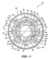
- Figure 1 is an end view of a constant velocity joint
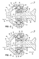
- Figure 2 is a cross section view along cut line 2-2 shown in Figure 1 ;
- Figure 3 is a cross section view along cut line 3-3 shown in Figure 1 ;
- Figure 4 is a force diagram indicating the forces acting on individual drive balls of the constant velocity joint.
- Figure 5 is an alternative embodiment of the constant velocity joint indicating the forces acting on individual drive balls of the constant velocity joint.
- a constant velocity joint is shown generally at 20.
- the constant velocity joint 20 rotatably couples a drive shaft 22 to a driven shaft 24.
- the constant velocity joint 20 permits relative rotation between the drive shaft 22 and the driven shaft 24 when the drive shaft 22 and the driven shaft 24 are angled relative to each other as is well known in the art.
- the constant velocity joint 20 includes an outer member 26.
- the outer member 26 includes an attachment end 28 for coupling the outer member 26 to the drive shaft 22.
- the drive shaft 22 is integrally formed with the outer member 26.
- the drive shaft 22 may be fixedly connected to the attachment end 28 of the outer member 26 by any suitable method.
- the outer member 26 defines an interior 30 and a plurality of outer member ball tracks 32, 34 within the interior 30.
- the interior 30 and the plurality of outer member ball tracks 32, 34 extend along a longitudinal axis L.
- the plurality of outer member ball tracks 32, 34 includes a first group of outer member ball tracks 32 and a second group of outer member ball tracks 34.
- the first group of outer member ball tracks 32 and the second group of outer member ball tracks 34 include a longitudinally arcuate profile extending along the longitudinal axis L, and a semi-circular cross section extending transverse to the longitudinal axis L.
- each of the first group of outer member ball tracks 32 and the second group of outer member ball tracks 34 defines an outer race center 36 positioned axially along the longitudinal axis L.
- first group of outer member ball tracks 32 and the second group of outer member ball tracks 34 may include a shape other than the arcuate profile shown and described herein.
- An inner member 38 is disposed within the interior 30 of the outer member 26.
- the inner member 38 defines an aperture 40 for receiving the driven shaft 24 therein, which extends away from the attachment end 28.
- the driven shaft 24 is coupled to the inner member 38 for rotation with the inner member 38.
- the aperture 40 and the driven shaft 24 may include complimentary splines for engaging each other. It should be appreciated, however, that the driven shaft 24 may be coupled to the inner member 38 in some other suitable manner not described herein.
- the inner member 38 defines a plurality of inner member ball tracks 42, 44, which extend along the longitudinal axis L.
- the plurality of inner member ball tracks 42, 44 includes a first group of inner member ball tracks 42 and a second group of inner member ball tracks 44.
- the first group of inner member ball tracks 42 and the second group of inner member ball tracks 44 include an arcuate profile extending along the longitudinal axis L, and a semi-circular cross section extending transverse to the longitudinal axis L.
- the arcuate profile of each of the first group of inner member ball tracks 42 and the second group of inner member ball tracks 44 define an inner race center 46 positioned axially along the longitudinal axis L.
- the first group of inner member ball tracks 42 and the second group of inner member ball tracks 44 may include a shape other than the arcuate profile shown and described herein.
- the first group of inner member ball tracks 42 opposes the first group of outer member ball tracks 32 to define a first group of funnels 48.
- the first group of inner member ball tracks 42 and the first group of outer member ball tracks 32 of the first group of funnels 48 are spaced from each other in non-parallel relationship relative to each other, and cooperate to define a first diverging width 50 between the first group of inner member ball tracks 42 and the first group of outer member ball tracks 32 that diverges toward the attachment end 28 in a first direction 52 along the longitudinal axis L to urge the drive balls 54 disposed within the first group of funnels 48 in the first direction 52.
- the arcuate profile of the first group of inner member ball tracks 42 and the first group of outer member ball tracks 32 cooperate such that the first group of funnels 48 includes an arcuate profile along the longitudinal axis L.
- the second group of inner member ball tracks 44 opposes the second group of outer member ball tracks 34 to define a second group of funnels 56.
- the second group of inner member ball tracks 44 and the second group of outer member ball tracks 34 of the second group of funnels 56 are spaced from each other in non-parallel relationship to define a second diverging width 58 between the second group of inner member ball tracks 44 and the second group of outer member ball tracks 34 that diverges away from the attachment end 28 in a second direction 60 along the longitudinal axis L to urge the drive balls 54 disposed within the second group of funnels 56 in the second direction 60.
- the arcuate profile of the second group of inner member ball tracks 44 and the second group of outer member ball tracks 34 cooperate such that the second group of funnels 56 includes an arcuate profile along the longitudinal axis L.
- the constant velocity joint 20 further comprises a plurality of drive balls 54.
- the plurality of drive balls 54 includes a spherical shape and transmits torque between the outer member 26 and the inner member 38.
- One of the plurality of drive balls 54 is disposed within each of the first group of funnels 48 and within each of the second group of funnels 56.
- Each of the drive balls 54 include a ball center 62 axially positioned along the longitudinal axis L.
- a cage 64 is disposed between the outer member 26 and the inner member 38.
- the cage 64 defines a plurality of windows 66 with one of the plurality of drive balls 54 disposed within each of the plurality of windows 66.
- the cage 64 maintains the drive balls 54 in a plane as the constant velocity joint 20 articulates to permit relative angular movement between the drive shaft 22 and the drive shaft 22.
- the first group of funnels 48 and the second group of funnels 56 are arranged radially about the longitudinal axis L in alternating relationship relative to each other.
- the first group of funnels 48 and the second group of funnels 56 are equally spaced from each other radially about the longitudinal axis L. Accordingly, there are an equal number of funnels in the first group of funnels 48 and in the second group of funnels 56.
- the first group of funnels 48 includes a group having four funnels and the second group of funnels 56 includes a group having four funnels.
- the number of funnels in the first group of funnels 48 and the number of funnels in the second group of funnels 56 may vary from that shown or described herein.
- the first diverging width 50 increases in value along the longitudinal axis L in the first direction 52 at a first rate of divergence.
- the second diverging width 58 increases in value along the longitudinal axis L in the second direction 60 at a second rate of divergence, which is different from the first rate of divergence.
- the difference between the first rate of divergence and the second rate of divergence results in a net force applied to the drive balls 54 in either the first direction 52 or the second direction 60 to steer the cage 64, i.e., to bias the cage 64 in one of the first direction 52 and the second direction 60.
- the direction the drive balls 54 are urged by the funnels 48, 56 is dependent upon the direction in which the funnels 48, 56 are diverging.
- the first group of funnels 48 diverges toward the attachment end 28 in the first direction 52, and therefore urges the drive balls 54 within the first group of funnels 48 in the first direction 52.
- the drive balls 54 are urged in the first direction 52 toward the attachment end 28.
- the second group of funnels 56 diverges away from the attachment end 28 in the second direction 60 and therefore urges the drive balls 54 within the second group of funnels 56 in the second direction 60.
- the drive balls 54 are urged in a second direction 60 away from the attachment end 28.
- first group of funnels 48 and the second group of funnels 56 include the arcuate profile along the longitudinal axis L
- the first rate of divergence and the second rate of divergence are variable along the longitudinal axis L because of the continuously changing slope of the arcuate profile relative to the longitudinal axis L.
- the arcuate profile of the first group of outer member ball tracks 32 is different from the arcuate profile of the second group of outer member ball tracks 34. So that the first diverging width 50 differs from the second diverging width 58.
- the arcuate profile of the first group of inner member ball tracks 42 is different from the arcuate profile of the second group of inner member ball tracks 44 so that the fist diverging width differs from the second diverging width 58.
- the first group of funnels 48 and the second group of funnels 56 do not include the arcuate profile, then the first rate of divergence and the second rate of divergence is not variable, but fixed.
- the first rate of divergence may be greater than the second rate of divergence to bias the cage 64 in the first direction 52, or alternatively, the second rate of divergence may be greater than the first rate of divergence to bias the cage 64 in the second direction 60.
- the first rate of divergence is greater than the second rate of divergence, with the second rate of divergence being preferably at least eighty percent (i.e, ⁇ is equal to 0.80%) of the first rate of divergence, and more preferably the second rate of divergence is at least ninety five percent (i.e, ⁇ is equal to 0.95%) of the first rate of divergence.
- the second rate of divergence is greater than the first rate of divergence, with the first rate of divergence being preferably at least eighty percent (i.e, ⁇ is equal to 0.80%) of the second rate of divergence, and more preferably the first rate of divergence is at least ninety five percent (i.e, ⁇ is equal to 0.95%) of the second rate of divergence.
- one way to control the direction in which the first group of funnels 48 and the second group of funnels 56 diverge is the relative placement of the inner race centers 46 and the outer race centers 36 along the longitudinal axis L. If the outer race center 36 is positioned along the longitudinal axis L farther from the attachment end 28 than the inner race center 46, with the ball center 62 positioned therebetween, the offset between the outer race center 36 and the inner race center 46 opens the diverging funnel toward the attachment end 28 and will urge the drive ball 54 in the first direction 52 toward the attachment end 28.
- the offset between the outer race center 36 and the inner race center 46 opens the diverging funnel away from the attachment end 28 and will urge the drive ball 54 in the second direction 60 away from the attachment end 28.
- each of the first group of inner member ball tracks 42 and the second group of inner member ball tracks 44 defines an inner race center 46 along the longitudinal axis L.
- the arcuate profile of each of the first group of outer member ball tracks 32 and the second group of outer member ball tracks 34 defines an outer race center 36 along the longitudinal axis L.
- the inner race centers 46 of the first group of inner member ball tracks 42 are spaced from the outer race centers 36 of the first group of outer member ball tracks 32 along the longitudinal axis L a first distance 68 to define a first offset
- the inner race centers 46 of the second group of inner member ball tracks 44 are spaced from the outer race centers 36 of the second group of outer member ball tracks 34 along the longitudinal axis L a second distance 70 different from the first distance 68 to define a second offset.
- the inner race centers 46 of the first group of inner member ball tracks 42 is farther from the attachment end 28 than the outer race centers 36 of the first group of outer member ball tracks 32 and the inner race centers 46 of the second group of inner member ball tracks 44 is nearer the attachment end 28 than the outer race centers 36 of the second group of outer member ball tracks 34.
Landscapes
- Engineering & Computer Science (AREA)
- General Engineering & Computer Science (AREA)
- Mechanical Engineering (AREA)
- Friction Gearing (AREA)
- Joints Allowing Movement (AREA)
- Crushing And Grinding (AREA)
Applications Claiming Priority (1)
| Application Number | Priority Date | Filing Date | Title |
|---|---|---|---|
| US11/950,047 US8414405B2 (en) | 2007-12-04 | 2007-12-04 | Fixed center constant velocity joint with different funnel offsets |
Publications (3)
| Publication Number | Publication Date |
|---|---|
| EP2068024A2 true EP2068024A2 (fr) | 2009-06-10 |
| EP2068024A3 EP2068024A3 (fr) | 2013-05-29 |
| EP2068024B1 EP2068024B1 (fr) | 2016-09-07 |
Family
ID=40414089
Family Applications (1)
| Application Number | Title | Priority Date | Filing Date |
|---|---|---|---|
| EP08169288.1A Ceased EP2068024B1 (fr) | 2007-12-04 | 2008-11-17 | Joint homocinétique fixe avec chemins de roulements de forme d'entonnoir differentes |
Country Status (2)
| Country | Link |
|---|---|
| US (1) | US8414405B2 (fr) |
| EP (1) | EP2068024B1 (fr) |
Families Citing this family (1)
| Publication number | Priority date | Publication date | Assignee | Title |
|---|---|---|---|---|
| US12234864B2 (en) * | 2018-06-15 | 2025-02-25 | Steering Solutions Ip Holding Corporation | Constant velocity joint with asymmetric opposed tracks |
Citations (1)
| Publication number | Priority date | Publication date | Assignee | Title |
|---|---|---|---|---|
| US6848999B2 (en) | 2002-05-10 | 2005-02-01 | Gkn Automotive Gmbh | Counter-track joint having identically orientated opposed pairs of tracks |
Family Cites Families (6)
| Publication number | Priority date | Publication date | Assignee | Title |
|---|---|---|---|---|
| US2046584A (en) * | 1934-08-08 | 1936-07-07 | Alfred H Rzeppa | Universal joint |
| US2325460A (en) | 1940-09-20 | 1943-07-27 | Walter E Amberg | Constant velocity universal joint |
| US3475924A (en) | 1968-08-01 | 1969-11-04 | Loehr & Bromkamp Gmbh | Universal joint |
| DE10060120B4 (de) * | 2000-12-04 | 2005-12-22 | Gkn Driveline International Gmbh | Kugelgleichlaufgelenk als Gegenbahngelenk |
| DE10304156B4 (de) * | 2003-02-03 | 2011-10-20 | Gkn Driveline International Gmbh | Gegenbahngelenk mit verbessertem Käfig |
| DE102005042909B4 (de) * | 2005-09-08 | 2015-06-18 | Gkn Driveline International Gmbh | Gegenbahngelenk mit begrenzter Axialverschiebung |
-
2007
- 2007-12-04 US US11/950,047 patent/US8414405B2/en active Active
-
2008
- 2008-11-17 EP EP08169288.1A patent/EP2068024B1/fr not_active Ceased
Patent Citations (1)
| Publication number | Priority date | Publication date | Assignee | Title |
|---|---|---|---|---|
| US6848999B2 (en) | 2002-05-10 | 2005-02-01 | Gkn Automotive Gmbh | Counter-track joint having identically orientated opposed pairs of tracks |
Also Published As
| Publication number | Publication date |
|---|---|
| EP2068024A3 (fr) | 2013-05-29 |
| US20090143150A1 (en) | 2009-06-04 |
| EP2068024B1 (fr) | 2016-09-07 |
| US8414405B2 (en) | 2013-04-09 |
Similar Documents
| Publication | Publication Date | Title |
|---|---|---|
| US6478684B2 (en) | Constant velocity joint and rolling bearing unit for wheel | |
| US9388860B2 (en) | Retaining ring for a constant velocity joint and method of assembly using the same | |
| US6902487B2 (en) | Longitudinal displacement unit with braking rollers | |
| KR20120023789A (ko) | 플런징 교차 트랙 등속 조인트 | |
| CA2415820A1 (fr) | Unite d'entrainement de roue | |
| US6817950B2 (en) | High angle constant velocity joint | |
| EP2299134B1 (fr) | Joint homocinétique du type fixe | |
| JP4248924B2 (ja) | 固定型等速自在継手 | |
| DE112006000412T5 (de) | Radlagervorrichtung mit integrierter Raddrehzahldetektionsvorrichtung und Verfahren zu ihrer Montage | |
| EP2831437B1 (fr) | Joint homocinétique | |
| EP2068024B1 (fr) | Joint homocinétique fixe avec chemins de roulements de forme d'entonnoir differentes | |
| EP2068025B1 (fr) | Joint de vitesse constante à centre fixe | |
| EP2532909B1 (fr) | Joint universel à billes pour un véhicule automobile | |
| US11187273B2 (en) | Propeller shaft assembly | |
| JP2003021159A (ja) | 等速自在継手 | |
| EP3327304B1 (fr) | Ensemble de joint à rigidité variable comportant un ensemble de douille | |
| US12345300B2 (en) | Tapered minor diameter spline to increase strength and fatigue life | |
| JP3767168B2 (ja) | 等速ジョイント及び等速ジョイント付車輪用転がり軸受ユニット | |
| EP1671044B1 (fr) | Joint homocinetique fixe pourvu de chemins de roulement a billes croises, arbre articule et procede de production du même | |
| US6971958B2 (en) | Apparatus and method for attachment and torque transfer for a constant velocity joint | |
| EP1950437B1 (fr) | Joint homocinétique fixe | |
| JP2002130317A (ja) | 等速自在継手及びこれを用いたプロペラシャフト | |
| US7448952B2 (en) | Light weight low angle fixed constant velocity joint and improved packaging | |
| US20040254022A1 (en) | Light weight low angle fixed constant velocity joint and improved packaging | |
| JP2006017143A (ja) | 等速ジョイント |
Legal Events
| Date | Code | Title | Description |
|---|---|---|---|
| PUAI | Public reference made under article 153(3) epc to a published international application that has entered the european phase |
Free format text: ORIGINAL CODE: 0009012 |
|
| AK | Designated contracting states |
Kind code of ref document: A2 Designated state(s): AT BE BG CH CY CZ DE DK EE ES FI FR GB GR HR HU IE IS IT LI LT LU LV MC MT NL NO PL PT RO SE SI SK TR |
|
| AX | Request for extension of the european patent |
Extension state: AL BA MK RS |
|
| RAP1 | Party data changed (applicant data changed or rights of an application transferred) |
Owner name: GM GLOBAL TECHNOLOGY OPERATIONS, INC. |
|
| RAP1 | Party data changed (applicant data changed or rights of an application transferred) |
Owner name: GM GLOBAL TECHNOLOGY OPERATIONS LLC |
|
| RAP1 | Party data changed (applicant data changed or rights of an application transferred) |
Owner name: STEERING SOLUTIONS IP HOLDING CORPORATION Owner name: GM GLOBAL TECHNOLOGY OPERATIONS LLC |
|
| PUAL | Search report despatched |
Free format text: ORIGINAL CODE: 0009013 |
|
| AK | Designated contracting states |
Kind code of ref document: A3 Designated state(s): AT BE BG CH CY CZ DE DK EE ES FI FR GB GR HR HU IE IS IT LI LT LU LV MC MT NL NO PL PT RO SE SI SK TR |
|
| AX | Request for extension of the european patent |
Extension state: AL BA MK RS |
|
| RIC1 | Information provided on ipc code assigned before grant |
Ipc: F16D 3/223 20110101AFI20130422BHEP |
|
| 17P | Request for examination filed |
Effective date: 20131129 |
|
| RBV | Designated contracting states (corrected) |
Designated state(s): AT BE BG CH CY CZ DE DK EE ES FI FR GB GR HR HU IE IS IT LI LT LU LV MC MT NL NO PL PT RO SE SI SK TR |
|
| AKX | Designation fees paid |
Designated state(s): DE GB |
|
| 17Q | First examination report despatched |
Effective date: 20140205 |
|
| GRAP | Despatch of communication of intention to grant a patent |
Free format text: ORIGINAL CODE: EPIDOSNIGR1 |
|
| INTG | Intention to grant announced |
Effective date: 20160317 |
|
| GRAS | Grant fee paid |
Free format text: ORIGINAL CODE: EPIDOSNIGR3 |
|
| GRAA | (expected) grant |
Free format text: ORIGINAL CODE: 0009210 |
|
| AK | Designated contracting states |
Kind code of ref document: B1 Designated state(s): DE GB |
|
| REG | Reference to a national code |
Ref country code: GB Ref legal event code: FG4D |
|
| REG | Reference to a national code |
Ref country code: DE Ref legal event code: R096 Ref document number: 602008046098 Country of ref document: DE |
|
| REG | Reference to a national code |
Ref country code: DE Ref legal event code: R097 Ref document number: 602008046098 Country of ref document: DE |
|
| PLBE | No opposition filed within time limit |
Free format text: ORIGINAL CODE: 0009261 |
|
| STAA | Information on the status of an ep patent application or granted ep patent |
Free format text: STATUS: NO OPPOSITION FILED WITHIN TIME LIMIT |
|
| 26N | No opposition filed |
Effective date: 20170608 |
|
| PGFP | Annual fee paid to national office [announced via postgrant information from national office to epo] |
Ref country code: DE Payment date: 20171129 Year of fee payment: 10 |
|
| PGFP | Annual fee paid to national office [announced via postgrant information from national office to epo] |
Ref country code: GB Payment date: 20171127 Year of fee payment: 10 |
|
| REG | Reference to a national code |
Ref country code: DE Ref legal event code: R119 Ref document number: 602008046098 Country of ref document: DE |
|
| GBPC | Gb: european patent ceased through non-payment of renewal fee |
Effective date: 20181117 |
|
| PG25 | Lapsed in a contracting state [announced via postgrant information from national office to epo] |
Ref country code: DE Free format text: LAPSE BECAUSE OF NON-PAYMENT OF DUE FEES Effective date: 20190601 |
|
| PG25 | Lapsed in a contracting state [announced via postgrant information from national office to epo] |
Ref country code: GB Free format text: LAPSE BECAUSE OF NON-PAYMENT OF DUE FEES Effective date: 20181117 |