EP2067985A2 - Starter with compact structure - Google Patents
Starter with compact structure Download PDFInfo
- Publication number
- EP2067985A2 EP2067985A2 EP08021091A EP08021091A EP2067985A2 EP 2067985 A2 EP2067985 A2 EP 2067985A2 EP 08021091 A EP08021091 A EP 08021091A EP 08021091 A EP08021091 A EP 08021091A EP 2067985 A2 EP2067985 A2 EP 2067985A2
- Authority
- EP
- European Patent Office
- Prior art keywords
- pinion
- shielding member
- gear
- ring gear
- starter
- Prior art date
- Legal status (The legal status is an assumption and is not a legal conclusion. Google has not performed a legal analysis and makes no representation as to the accuracy of the status listed.)
- Granted
Links
Images


Classifications
-
- F—MECHANICAL ENGINEERING; LIGHTING; HEATING; WEAPONS; BLASTING
- F02—COMBUSTION ENGINES; HOT-GAS OR COMBUSTION-PRODUCT ENGINE PLANTS
- F02N—STARTING OF COMBUSTION ENGINES; STARTING AIDS FOR SUCH ENGINES, NOT OTHERWISE PROVIDED FOR
- F02N15/00—Other power-operated starting apparatus; Component parts, details, or accessories, not provided for in, or of interest apart from groups F02N5/00 - F02N13/00
- F02N15/02—Gearing between starting-engines and started engines; Engagement or disengagement thereof
- F02N15/04—Gearing between starting-engines and started engines; Engagement or disengagement thereof the gearing including disengaging toothed gears
- F02N15/06—Gearing between starting-engines and started engines; Engagement or disengagement thereof the gearing including disengaging toothed gears the toothed gears being moved by axial displacement
-
- F—MECHANICAL ENGINEERING; LIGHTING; HEATING; WEAPONS; BLASTING
- F02—COMBUSTION ENGINES; HOT-GAS OR COMBUSTION-PRODUCT ENGINE PLANTS
- F02N—STARTING OF COMBUSTION ENGINES; STARTING AIDS FOR SUCH ENGINES, NOT OTHERWISE PROVIDED FOR
- F02N11/00—Starting of engines by means of electric motors
-
- F—MECHANICAL ENGINEERING; LIGHTING; HEATING; WEAPONS; BLASTING
- F02—COMBUSTION ENGINES; HOT-GAS OR COMBUSTION-PRODUCT ENGINE PLANTS
- F02N—STARTING OF COMBUSTION ENGINES; STARTING AIDS FOR SUCH ENGINES, NOT OTHERWISE PROVIDED FOR
- F02N2250/00—Problems related to engine starting or engine's starting apparatus
- F02N2250/08—Lubrication of starters; Sealing means for starters
-
- Y—GENERAL TAGGING OF NEW TECHNOLOGICAL DEVELOPMENTS; GENERAL TAGGING OF CROSS-SECTIONAL TECHNOLOGIES SPANNING OVER SEVERAL SECTIONS OF THE IPC; TECHNICAL SUBJECTS COVERED BY FORMER USPC CROSS-REFERENCE ART COLLECTIONS [XRACs] AND DIGESTS
- Y10—TECHNICAL SUBJECTS COVERED BY FORMER USPC
- Y10T—TECHNICAL SUBJECTS COVERED BY FORMER US CLASSIFICATION
- Y10T74/00—Machine element or mechanism
- Y10T74/13—Machine starters
Definitions
- the starter device is of the type including a housing 100 having a nose portion 101 protruding toward an engine and internally formed with an opening portion 102, and a motor 110 fixedly mounted on the housing 100.
- the motor 110 has an armature 111 provided with an armature shaft 111a, to which an output shaft 150 is connected via a speed reduction gear unit 120 and a clutch 130.
- the output shaft 150 has one axial end, placed in opposition to the motor 110, which is rotatably supported with the nose portion 101 at a distal end thereof via a bearing 140.
- the output shaft 150 has an outer circumferential periphery formed with a spline 102, to which a spline tube 160 is held in spline coupling engagement.
- the spline tube 160 has one axial end integrally formed with a pinion gear 170.
- a shift lever 190 is drivably actuated to push the spline tube 160 toward the engine (rightward as viewed in FIG. 4 ). This causes the pinion gear 170 to be brought into meshing engagement with the ring gear 200 of the engine.
- the present invention has been completed with a view to addressing the above issues and has an object to provide a starter that can suppress grit and dust or water droplets from intruding from an opening portion of a nose portion to an inside of a housing to prevent the occurrence of degraded performance and defective operation of the starter.
- the present invention provides a starter comprising a housing having an engine mounting surface adapted to rest on an engine having a ring gear, and a nose portion extending from the engine mounting portion toward the engine and having an opening portion, a motor fixedly mounted on the housing and having an armature generating a rotational force and an armature shaft on which the armature is supported, an output shaft disposed in a coaxial relationship with the armature shaft and having axial ends one end of which is rotatably supported with the nose portion by means of a bearing at a position opposite to the motor, and a pinion moving body having a pinion gear operative to mesh with the ring gear to transfer the rotational force to the ring gear and fitted on the output shaft at an outer periphery thereof in helical spline engagement.
- the pinion moving body comprises a pinion shielding member connected to the pinion gear at one end axially placed in opposition to the ring gear.
- the pinion shielding member has an outer circumferential periphery, having an outer diameter greater than a diameter of an addendum circle of the pinion gear, and a bottomed cylindrical configuration formed with a hollow portion having one axial end facing the ring gear and opened and the other axial end directed in opposition to the ring gear and closed.
- the pinion shielding member has the outer circumferential periphery with the outer diameter greater than the diameter of the addendum circle of the pinion gear.
- the starter can have a clearance between an inner circumferential portion of the nose portion and the outer circumferential periphery of the pinion shielding member that is made less than a clearance between the inner circumferential portion of the nose portion and the diameter of the addendum circle of the pinion gear.
- the pinion shielding member has a function to serve as water proofing wall. This suppresses foreign materials such as grit and dust or water droplets, collected up by the ring gear, from intruding to the inside of the housing.
- the pinion shielding member has the hollow portion having one axial end facing the ring gear and opened and the other axial end directed in opposition to the ring gear and closed. Therefore, even if the water droplets, collected up by the ring gear, intrude from the opening portion of the nose portion into the hollow portion, the hollow portion can block the intrusion of the water droplets. Thus, no risk takes place for the water droplets intrude into a further inside area of the starter.
- a water flow, intruded from the opening portion of the nose portion has a momentum that is weakened with the hollow portion, providing improved effect of preventing the intrusion of water.
- the nose portion of the housing and the pinion shielding member may preferably have a relationship in that a clearance, defined between an inner circumferential periphery of the nose portion and the outer circumferential periphery of the pinion shielding member, is kept constant in an area starting from a stop position, in which the pinion disengages from the ring gear to be halted, to a meshing position in which the pinion meshes with the ring gear.
- the pinion shielding member may preferably have a plurality of ribs radially extending between an inner periphery and an outer periphery of the hollow portion.
- the hollow portion provided with the plural ribs compensates for the drop in strength of the pinion shielding member caused by the formation of the hollow portion.
- the hollow portion is divided with the ribs into a plurality of compartments, which can minimize the momentum of a water stream intruded into the hollow portion, thereby providing an increased effect of preventing water from intruding to the inside of the housing.
- the pinion shielding member may be preferably made of resin separately from the pinion gear and assembled to the pinion gear by snap fitting with elasticity.
- Providing the pinion shielding member independently of the pinion gear enables the pinion shielding member to be easily formed by resin molding, while enabling the pinion gear and the pinion shielding member to be easily assembled in a snap fitting fashion.
- an electromagnetic switch may be further preferably provided to be operative to form an electromagnet providing an attraction force to drive a shift lever for moving the pinion moving body toward the ring gear of the engine, wherein the pinion shielding member is integrally formed with a lever engaging portion held in engagement with the shift lever.
- the term "front” refers to a front portion of a component part at a position axially closer to an engine or a ring gear of the engine, i.e., an area oriented in a direction opposite to a motor incorporated in a starter to which the present invention is related.
- the term “rear” refers to a rear portion of the component part closer to the motor incorporated in the starter, i.e., the other area oriented in a direction opposite to the engine.
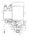
- FIG. 1 is a cross sectional view showing the starter 1 of the present embodiment implementing the present invention.
- the starter 1 of the present embodiment includes a motor 2 having an armature (not shown) for generating a rotational force, an output shaft 3 to which the rotational force is transferred from the armature through a clutch (not shown), a pinion moving body PM (described later) located on the output shaft 3 at its outer circumferential periphery, an electromagnetic switch 5 having not only a function to open or close a main contact (not shown) disposed in an energization circuit (motor circuit) of the motor 2 but also a function to move the pinion moving body PM via a shift lever 4 in an axial direction, and a housing 6 to which the motor 2 and the electromagnetic switch 5 are fixedly mounted.
- the motor 2 is a well-known DC electric motor operative such that with the main contact being closed upon energization of the electromagnetic switch 5, the DC electric motor is supplied with electric power from an on-vehicle battery (not shown) to cause the armature to generate the rotational force.
- the clutch takes the form of a one-way clutch that is operative to transfer drive torque from the motor 2 to the output shaft 3 during a startup of an engine whereas when an engine rotation is transferred to the starter 1 due to the startup of the engine, a power transfer path between an input and an output (on a side of the output shaft) is disconnected to interrupt a transfer of torque for preventing the engine rotation from being transferred to the input (on the side of the motor) of the clutch.
- a speed reduction gear unit may be disposed between the motor 2 and the clutch.
- the speed reduction gear unit may preferably include a planetary gear type speed reduction gear device that can achieve a speed reduction on, for instance, the same axis as that of the armature shaft of the motor 2.
- the output shaft 3 placed on the same axis as that of the armature shaft in a coaxial relation, has an axial front end 3a, axially placed in opposition to the motor 2 and rotatably supported with a bearing 7 mounted on a distal end of the housing 6 at a nose portion 6a thereof, and an axial rear end that is closer to the motor 2 and connected to the clutch.
- the electromagnetic switch device 5 is comprised of an electromagnetic coil (not shown) operative to be energized with electric power delivered from the one-vehicle battery due to a starter switch (not shown) being closed in operation, and a plunger 8 disposed in the electromagnetic coil to be movable therethrough.
- an electromagnetic coil (not shown) operative to be energized with electric power delivered from the one-vehicle battery due to a starter switch (not shown) being closed in operation
- a plunger 8 disposed in the electromagnetic coil to be movable therethrough.
- the housing 6 has the nose portion 6a that protrudes from a mounting surface 6b, operative to rest on the engine, in a front direction (rightward as viewed in FIG. 1 ) opposite to the motor 2.
- the nose portion 6a is internally formed with an opening portion 6c to accommodate therein a pinion gear 9 and a ring gear 10 of the engine that are operative to be brought into meshing engagement with each other in a manner as described below in detail.
- the pinion moving body PM is comprised of the pinion gear 9 and a pinion shielding member 11.
- the pinion gear 9 is coupled to an outer circumferential periphery of the output shaft 3 in a helical spline engagement to be rotatable unitarily with the output shaft 3 to have a function to transfer the rotational force of the motor 2 to the ring gear 10.
- the pinion gear 9 is made of, for instance, iron, and has an axial rear end, placed in opposition to the ring gear 10, which is unitarily formed with a trunk portion 9a (see FIG 1 ) having an outer circumferential periphery formed with an annular circumferential recess 9b.
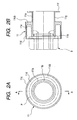
- the pinion shielding member 11 made of, for instance, resin separately from the pinion gear 9, is fitted to the trunk portion 9a of the pinion gear 9 in assembly by means of a snap fitting fashion utilizing elasticity to be rotatable relative to the pinion gear 9. That is, the pinion shielding member 11 has a cylindrical portion 11a which can be fitted to the trunk portion 9a of the pinion gear 9 as shown in FIGS. 2A and 2B .
- the cylindrical portion 11 a has a front end axial internally formed with a radially inwardly protruding a ring-shaped claw portion 11b, which is fitted to the annular circumferential recess 9b formed on the trunk portion 9a of the pinion gear 9. This allows the cylindrical portion 11a to be easily assembled to the pinion gear 9.
- the pinion shielding member 11 has an outer circumferential cylindrical portion 11c having an outer diameter larger than that of an addendum circle of the pinion gear 9.
- the outer circumferential cylindrical portion 11c is formed in a bottomed ring-shaped configuration, having a radially extending bottom wall 11cb connected to the cylindrical portion 11a at a rear end thereof, which is internally formed with an annular hollow portion 11d defined between the cylindrical portion 11 a and the outer circumferential portion 11c.
- the annular hollow portion 11d has a front axial end that is opened and a rear end closed with the bottom wall 11cb.
- the annular hollow portion 11d of the pinion shielding member 11 is opened in an area radially outward of the diameter (indicated by a phantom line P in FIG. 2A ) of the addendum circle of the pinion gear 9 as viewed the pinion shielding member 11 in an axial direction from the pinion gear 9 as shown in FIG 2A .
- the clearance between the inner peripheral surface of the opening portion 6c of the nose portion 6a and the outer circumferential periphery of the outer cylindrical portion 11c of the pinion shielding member 11 is set to an extent as small as possible to ensure the pinion moving body PM is prevented from conflicting the inner circumferential periphery of the opening portion 6c of the nose portion 6a during movement of the pinion moving body PM in the axial direction.
- the clearance between the inner peripheral surface of the opening portion 6c of the nose portion 6a and the outer circumferential periphery of the outer cylindrical portion 11 c of the pinion shielding member 11 is formed to have an approximately constant value in an area from a stop position of the pinion gear 9 to a meshing position at which the pinion gear 9 meshes with the ring gear 10. That is, between the stop position and the meshing position of the pinion gear 9, no remarkable variation takes place in the clearance between the outer circumferential periphery of the outer cylindrical portion 11c and the inner peripheral surface of the opening portion 6c of the nose portion 6a, which is kept nearly constant.
- the pinion shielding member 11 has a barrel portion 11e formed integrally with a rear end of the cylindrical portion 11a at a position opposite to the pinion gear in a coaxial relationship.
- the barrel portion 11e has a rear end formed with an annular flange portion 11f with an annular recess 11g being defined between the bottom wall 11cb and the annular flange 11f.
- the annular recess 11g of the barrel portion 11e accommodates therein the shift lever 4.
- the electromagnetic coil is energized to form the electromagnet. Then, the electromagnet attracts the plunger 8 with the movement of the plunger 8 being transferred to the pinion shielding member 11 via the shift lever 4. This causes the pinion shielding member 11 to rotate on the output shaft 3 due to an action of the helical spline to be axially pushed toward the ring gear 10 of the engine (leftward as viewed in FIG. 1 ) such that the pinion gear 9 is brought into meshing engagement with the ring gear 10.
- the movement of the plunger 8 results in a consequence of closing the main contact of the motor circuit, thereby permitting the battery to apply the motor 2 with electric power to cause the armature to generate the rotational force.
- the rotation of the armature is transferred to the output shaft 3 via the clutch, causing the pinion gear 9 to rotate unitarily with the output shaft 3.
- drive torque of the motor 2 is transferred from the pinion gear 9 to the ring gear 10, thereby cranking up the engine.
- the electromagnetic coil is de-energized to diminish the electromagnet. This causes the plunger 8 to be pushed back to its original position due to the reactive force stored in the return spring. As a result, the main contact is opened and no electric power is supplied from the battery to the motor 2. Thus, the armature gradually decelerates to halt in operation.
- the pinion shielding member 11 formed on the pinion moving body PM, has the outer circumferential periphery with an outer diameter greater than that of the addendum circle of the pinion gear 9. This enables the clearance between the inner peripheral surface of the opening portion 6c of the nose portion 6a and the outer circumferential periphery of the outer cylindrical portion 11c to be less than the clearance between the inner peripheral surface of the opening portion 6c of the nose portion 6a and the outer diameter of the addendum circle of the pinion gear 9.
- the pinion shielding member 11 has a function to serve as a water-proofing wall. This avoids foreign materials such as grit and dust or water droplets or the like collected by the ring gear 10 from intruding from the opening portion 6c of the nose portion 6a into the inside of the housing 6.
- the pinion shielding member 11 is formed with the annular hollow portion 11d having the front end being opened in the axial direction and the rear end closed with the radially extending bottom wall 11cb. Therefore, even if the water droplets, collected by the ring gear 10, intrude from the opening portion 6c of the nose portion 6a of the housing 6 into the annular hollow portion 11d, the annular hollow portion 11d blocks the entry of the water droplets. This blocks the water droplets from further intruding to the inside of the starter 1. In addition, the annular hollow portion 11d weakens the momentum of any water stream intruding from the opening portion 6c of the nose portion 6a of the housing 6, thereby improving an effect of preventing the water intrusion.
- the clearance between the inner peripheral surface of the opening portion 6c of the nose portion 6a and the outer circumferential periphery of the pinion shielding member 11 is kept approximately constant. This suppresses foreign materials and water droplets or the like from intruding into the inside of the housing 6 regardless of the positions (stop position and the meshing position) of the pinion gear 9.
- the pinion shielding member 11 can be easily formed by resin-molding and the pinion gear 9 and the pinion shielding member 11 can be readily assembled to each other with snap fitting action.
- the barrel portion 11e can be easily formed integrally with the pinion shielding member 11 to engage with the shift lever 4, resulting in an effect of achieving a reduction in the number of component parts.
- the pinion moving body PM is comprised of the pinion gear 9 and the pinion shielding member 11 formed in separate bodies and the pinion gear 9 is made of iron while the pinion shielding member 11 is made of resin with lower density than that of the pinion gear 9, enabling a reduction in mass of the pinion shielding member 11.
- a pinion shielding member of a modified form is described below with reference to FIGS. 3A and 3B .
- FIG. 3A shows a front view of the pinion shielding member 11A of the modified form
- FIG. 3B is a cross sectional view of the pinion shielding member 11A of the modified form shown in FIG. 3A .
- the pinion shielding member 11A has a plurality of ribs 11h axially extending through the annular hollow portion 11d at circumferentially spaced positions and having rear ends formed integrally with the bottom wall 11cb of the pinion shielding member 11A.
- the pinion shielding member 11A includes the cylindrical portion 11a, serving as an inner circumferential wall of the annular hollow portion 11d, and the outer cylindrical portion, serving as an outer circumferential wall of the annular hollow portion 11d, with the plurality of ribs 11h radially interconnecting the inner and outer circumferential walls of the inner and outer cylindrical portions 11a and 11c, respectively.
- the plurality of ribs 11h are placed at circumferentially equidistantly spaced intervals, thereby partitioning the annular hollow portion 11d into a plurality of small compartments 11i.
- the ribs 11h formed in the annular hollow portion 11d compensates for a drop in rigidity of the pinion shielding member 11 A caused by the formation of the annular hollow portion 11d.
- the annular hollow portion 11d is divided into the plurality of small compartments 11i defined with the plurality of ribs 11h. This suppresses the momentum of the water stream intruding to the annular hollow portion 11d, thereby providing an increased effect of suppressing the intrusion of water to the inside of the housing 6.
- both of these component parts may be formed of the same material in a unitary structure.
- the pinion shielding member 11 may be possibly formed by, for instance, cutting and forging or the like.
Landscapes
- Engineering & Computer Science (AREA)
- Chemical & Material Sciences (AREA)
- Combustion & Propulsion (AREA)
- Mechanical Engineering (AREA)
- General Engineering & Computer Science (AREA)
- Connection Of Motors, Electrical Generators, Mechanical Devices, And The Like (AREA)
- Sealing Using Fluids, Sealing Without Contact, And Removal Of Oil (AREA)
- Sealing Of Bearings (AREA)
Abstract
Description
- This application is based on Japanese Patent Application No.
2007-317543, filed on December 7, 2007 -
- 1. Technical Field of the Invention
The present invention relates to starters and, more particularly, to a starter the type in which a minion moving body, held in helical spline engagement with an output shaft at an outer circumferential periphery thereof, which is pushed toward an engine (in a direction opposite to a motor) to cause a pinion gear to be brought into meshing engagement with a ring gear. - 2. Description of the Related Art
In the related art, there has been known a starter, which is disclosed in Japanese Patent Application Publication No.2006-207573 - With such a structure shown in
FIG. 4 , the starter device is of the type including ahousing 100 having anose portion 101 protruding toward an engine and internally formed with anopening portion 102, and amotor 110 fixedly mounted on thehousing 100. Themotor 110 has anarmature 111 provided with anarmature shaft 111a, to which anoutput shaft 150 is connected via a speedreduction gear unit 120 and aclutch 130. Theoutput shaft 150 has one axial end, placed in opposition to themotor 110, which is rotatably supported with thenose portion 101 at a distal end thereof via abearing 140. Theoutput shaft 150 has an outer circumferential periphery formed with aspline 102, to which aspline tube 160 is held in spline coupling engagement. Thespline tube 160 has one axial end integrally formed with apinion gear 170. When anelectromagnetic switch 180 is energized, ashift lever 190 is drivably actuated to push thespline tube 160 toward the engine (rightward as viewed inFIG. 4 ). This causes thepinion gear 170 to be brought into meshing engagement with thering gear 200 of the engine. - With the starter of such a related art, no issue occurs in normal use. However, under a situation where a vehicle runs on, for instance, a punishing road with the starter being used under an extremely adverse condition, there occurs a risk in which foreign materials such as grit and dust or water droplets, etc., collected by the
ring gear 200 intrude inside of the starter through theopening portion 102 of thehousing 100. Moisture, containing grit and dust or the like, causes defective sliding engagements to occur when intruded into sliding sections such as the speed reduction gear unit 12 and theclutch 130, etc. - With the starter of such a related art described above, however, no expedient measure has been undertaken for suppressing the intrusion of grit and dust or water droplets with a concern for degraded performance and defective operation of the starter resulting from defective sliding engagements of as the speed reduction gear unit 12 and the
clutch 130 or rusting results of internal component parts. - The present invention has been completed with a view to addressing the above issues and has an object to provide a starter that can suppress grit and dust or water droplets from intruding from an opening portion of a nose portion to an inside of a housing to prevent the occurrence of degraded performance and defective operation of the starter.
- To achieve the above object, the present invention provides a starter comprising a housing having an engine mounting surface adapted to rest on an engine having a ring gear, and a nose portion extending from the engine mounting portion toward the engine and having an opening portion, a motor fixedly mounted on the housing and having an armature generating a rotational force and an armature shaft on which the armature is supported, an output shaft disposed in a coaxial relationship with the armature shaft and having axial ends one end of which is rotatably supported with the nose portion by means of a bearing at a position opposite to the motor, and a pinion moving body having a pinion gear operative to mesh with the ring gear to transfer the rotational force to the ring gear and fitted on the output shaft at an outer periphery thereof in helical spline engagement. The pinion moving body comprises a pinion shielding member connected to the pinion gear at one end axially placed in opposition to the ring gear. The pinion shielding member has an outer circumferential periphery, having an outer diameter greater than a diameter of an addendum circle of the pinion gear, and a bottomed cylindrical configuration formed with a hollow portion having one axial end facing the ring gear and opened and the other axial end directed in opposition to the ring gear and closed.
- With the starter of such a structure, the pinion shielding member has the outer circumferential periphery with the outer diameter greater than the diameter of the addendum circle of the pinion gear. Thus, the starter can have a clearance between an inner circumferential portion of the nose portion and the outer circumferential periphery of the pinion shielding member that is made less than a clearance between the inner circumferential portion of the nose portion and the diameter of the addendum circle of the pinion gear. In this case, the pinion shielding member has a function to serve as water proofing wall. This suppresses foreign materials such as grit and dust or water droplets, collected up by the ring gear, from intruding to the inside of the housing.
- Further, the pinion shielding member has the hollow portion having one axial end facing the ring gear and opened and the other axial end directed in opposition to the ring gear and closed. Therefore, even if the water droplets, collected up by the ring gear, intrude from the opening portion of the nose portion into the hollow portion, the hollow portion can block the intrusion of the water droplets. Thus, no risk takes place for the water droplets intrude into a further inside area of the starter. In addition, a water flow, intruded from the opening portion of the nose portion, has a momentum that is weakened with the hollow portion, providing improved effect of preventing the intrusion of water.
- With the starter of the present embodiment, the nose portion of the housing and the pinion shielding member may preferably have a relationship in that a clearance, defined between an inner circumferential periphery of the nose portion and the outer circumferential periphery of the pinion shielding member, is kept constant in an area starting from a stop position, in which the pinion disengages from the ring gear to be halted, to a meshing position in which the pinion meshes with the ring gear.
- With such a structure, foreign materials or water droplets, etc., can be prevented from intruding to the inside of the housing regardless of positions (a stop position and a meshing position) in which the pinion gear is placed.
- With the starter of the present embodiment, the pinion shielding member may preferably have a plurality of ribs radially extending between an inner periphery and an outer periphery of the hollow portion.
- Providing the hollow portion provided with the plural ribs compensates for the drop in strength of the pinion shielding member caused by the formation of the hollow portion. Moreover, the hollow portion is divided with the ribs into a plurality of compartments, which can minimize the momentum of a water stream intruded into the hollow portion, thereby providing an increased effect of preventing water from intruding to the inside of the housing.
- With the starter of the present embodiment, the pinion shielding member may be preferably made of resin separately from the pinion gear and assembled to the pinion gear by snap fitting with elasticity.
- Providing the pinion shielding member independently of the pinion gear enables the pinion shielding member to be easily formed by resin molding, while enabling the pinion gear and the pinion shielding member to be easily assembled in a snap fitting fashion.
- With the starter of the present embodiment, an electromagnetic switch may be further preferably provided to be operative to form an electromagnet providing an attraction force to drive a shift lever for moving the pinion moving body toward the ring gear of the engine, wherein the pinion shielding member is integrally formed with a lever engaging portion held in engagement with the shift lever.
- With the pinion shielding member integrally formed with the lever engaging portion, the number of component parts can be reduced in the starter.
-
-
FIG. 1 is a cross sectional view showing an overall structure of a starter of an embodiment according to the present invention. -
FIG. 2A is a plan view of a pinion shielding member, forming part of the starter shown inFIG 1 , as viewed in an axial direction. -
FIG. 2B is a cross sectional view of the pinion shielding member taken on line A-A ofFIG. 2A . -
FIG. 3A is a plan view of a pinion shielding member of a modified form as viewed in an axial direction. -
FIG. 3B is a cross sectional view of the pinion shielding member taken on line B-B ofFIG. 3A . -
FIG. 4 is a cross sectional view of a starter of the related art. - Now, a starter of one embodiment according to the present invention will be described below in detail with reference to the accompanying drawings. However, the present invention is construed not to be limited to such an embodiment described below and technical concepts of the present invention may be implemented in combination with other known technologies or the other technology having functions equivalent to such known technologies.
- In the following description, it is to be understood that such terms as "front", "rear", "axial", "outer", "inner", "radial", "outward", "rightward", "leftward", "circumferential", "distal", "end" and the like are words of convenience and are not to be construed as limiting terms.
- Further, as used herein, the term "front" refers to a front portion of a component part at a position axially closer to an engine or a ring gear of the engine, i.e., an area oriented in a direction opposite to a motor incorporated in a starter to which the present invention is related. Likewise, the term "rear" refers to a rear portion of the component part closer to the motor incorporated in the starter, i.e., the other area oriented in a direction opposite to the engine.
- The starter of an embodiment according to the present invention will be described below in detail with reference to the accompanying drawings.
-
FIG. 1 is a cross sectional view showing the starter 1 of the present embodiment implementing the present invention. - As shown in
FIG. 1 , the starter 1 of the present embodiment includes amotor 2 having an armature (not shown) for generating a rotational force, anoutput shaft 3 to which the rotational force is transferred from the armature through a clutch (not shown), a pinion moving body PM (described later) located on theoutput shaft 3 at its outer circumferential periphery, anelectromagnetic switch 5 having not only a function to open or close a main contact (not shown) disposed in an energization circuit (motor circuit) of themotor 2 but also a function to move the pinion moving body PM via ashift lever 4 in an axial direction, and ahousing 6 to which themotor 2 and theelectromagnetic switch 5 are fixedly mounted. - The
motor 2 is a well-known DC electric motor operative such that with the main contact being closed upon energization of theelectromagnetic switch 5, the DC electric motor is supplied with electric power from an on-vehicle battery (not shown) to cause the armature to generate the rotational force. - The clutch takes the form of a one-way clutch that is operative to transfer drive torque from the
motor 2 to theoutput shaft 3 during a startup of an engine whereas when an engine rotation is transferred to the starter 1 due to the startup of the engine, a power transfer path between an input and an output (on a side of the output shaft) is disconnected to interrupt a transfer of torque for preventing the engine rotation from being transferred to the input (on the side of the motor) of the clutch. - Further, a speed reduction gear unit may be disposed between the
motor 2 and the clutch. The speed reduction gear unit may preferably include a planetary gear type speed reduction gear device that can achieve a speed reduction on, for instance, the same axis as that of the armature shaft of themotor 2. - The
output shaft 3, placed on the same axis as that of the armature shaft in a coaxial relation, has an axialfront end 3a, axially placed in opposition to themotor 2 and rotatably supported with a bearing 7 mounted on a distal end of thehousing 6 at anose portion 6a thereof, and an axial rear end that is closer to themotor 2 and connected to the clutch. - The
electromagnetic switch device 5 is comprised of an electromagnetic coil (not shown) operative to be energized with electric power delivered from the one-vehicle battery due to a starter switch (not shown) being closed in operation, and aplunger 8 disposed in the electromagnetic coil to be movable therethrough. With the electromagnetic coil being energized to form an electromagnet, the electromagnet attracts theplunger 8 to close the main contact in operation. In contrast, with the electromagnetic coil being de-energized to distinguish the attraction force of the electromagnet, theplunger 8 is pushed back to its original position by the action of a reactive force stored in a return spring (not shown) to open the main contact in operation. - The
housing 6 has thenose portion 6a that protrudes from a mountingsurface 6b, operative to rest on the engine, in a front direction (rightward as viewed inFIG. 1 ) opposite to themotor 2. Thenose portion 6a is internally formed with anopening portion 6c to accommodate therein apinion gear 9 and aring gear 10 of the engine that are operative to be brought into meshing engagement with each other in a manner as described below in detail. - Next, an overall structure of the pinion moving body PM, implementing the present invention, will be described below in detail.
- The pinion moving body PM is comprised of the
pinion gear 9 and apinion shielding member 11. - The
pinion gear 9 is coupled to an outer circumferential periphery of theoutput shaft 3 in a helical spline engagement to be rotatable unitarily with theoutput shaft 3 to have a function to transfer the rotational force of themotor 2 to thering gear 10. Thepinion gear 9 is made of, for instance, iron, and has an axial rear end, placed in opposition to thering gear 10, which is unitarily formed with atrunk portion 9a (seeFIG 1 ) having an outer circumferential periphery formed with an annularcircumferential recess 9b. - The
pinion shielding member 11, made of, for instance, resin separately from thepinion gear 9, is fitted to thetrunk portion 9a of thepinion gear 9 in assembly by means of a snap fitting fashion utilizing elasticity to be rotatable relative to thepinion gear 9. That is, thepinion shielding member 11 has acylindrical portion 11a which can be fitted to thetrunk portion 9a of thepinion gear 9 as shown inFIGS. 2A and 2B . Thecylindrical portion 11 a has a front end axial internally formed with a radially inwardly protruding a ring-shapedclaw portion 11b, which is fitted to the annularcircumferential recess 9b formed on thetrunk portion 9a of thepinion gear 9. This allows thecylindrical portion 11a to be easily assembled to thepinion gear 9. - The
pinion shielding member 11 has an outer circumferentialcylindrical portion 11c having an outer diameter larger than that of an addendum circle of thepinion gear 9. The outer circumferentialcylindrical portion 11c is formed in a bottomed ring-shaped configuration, having a radially extending bottom wall 11cb connected to thecylindrical portion 11a at a rear end thereof, which is internally formed with an annularhollow portion 11d defined between thecylindrical portion 11 a and the outercircumferential portion 11c. The annularhollow portion 11d has a front axial end that is opened and a rear end closed with the bottom wall 11cb. In addition, with thepinion shielding member 11 assembled to thepinion gear 9 in assembly, the annularhollow portion 11d of thepinion shielding member 11 is opened in an area radially outward of the diameter (indicated by a phantom line P inFIG. 2A ) of the addendum circle of thepinion gear 9 as viewed thepinion shielding member 11 in an axial direction from thepinion gear 9 as shown inFIG 2A . - With the
pinion gear 9 disengaged from thering gear 10 of the engine to stay under a halted condition (at a position shown inFIG. 1 ), there is a slight amount of clearance (in the order of, for instance, approximately 0.5 to 2.0mm) between an inner peripheral surface of theopening portion 6c of thenose portion 6a and an outer circumferential periphery of the outercylindrical portion 11c of thepinion shielding member 11. This clearance is set to be less than that created between the inner peripheral surface of theopening portion 6c of thenose portion 6a and the outer diametric periphery of thepinion gear 9 at the addendum circle thereof (seeFIG. 1 ). - In other word, the clearance between the inner peripheral surface of the
opening portion 6c of thenose portion 6a and the outer circumferential periphery of the outercylindrical portion 11c of thepinion shielding member 11 is set to an extent as small as possible to ensure the pinion moving body PM is prevented from conflicting the inner circumferential periphery of theopening portion 6c of thenose portion 6a during movement of the pinion moving body PM in the axial direction. - Further, the clearance between the inner peripheral surface of the
opening portion 6c of thenose portion 6a and the outer circumferential periphery of the outercylindrical portion 11 c of thepinion shielding member 11 is formed to have an approximately constant value in an area from a stop position of thepinion gear 9 to a meshing position at which thepinion gear 9 meshes with thering gear 10. That is, between the stop position and the meshing position of thepinion gear 9, no remarkable variation takes place in the clearance between the outer circumferential periphery of the outercylindrical portion 11c and the inner peripheral surface of theopening portion 6c of thenose portion 6a, which is kept nearly constant. - Furthermore, with the present embodiment, the
pinion shielding member 11 has abarrel portion 11e formed integrally with a rear end of thecylindrical portion 11a at a position opposite to the pinion gear in a coaxial relationship. Thebarrel portion 11e has a rear end formed with anannular flange portion 11f with anannular recess 11g being defined between the bottom wall 11cb and theannular flange 11f. Theannular recess 11g of thebarrel portion 11e accommodates therein theshift lever 4. - Next, the operation of the starter 1 is described below.
- As a starter switch is closed in operation, the electromagnetic coil is energized to form the electromagnet. Then, the electromagnet attracts the
plunger 8 with the movement of theplunger 8 being transferred to thepinion shielding member 11 via theshift lever 4. This causes thepinion shielding member 11 to rotate on theoutput shaft 3 due to an action of the helical spline to be axially pushed toward thering gear 10 of the engine (leftward as viewed inFIG. 1 ) such that thepinion gear 9 is brought into meshing engagement with thering gear 10. - Meanwhile, the movement of the
plunger 8 results in a consequence of closing the main contact of the motor circuit, thereby permitting the battery to apply themotor 2 with electric power to cause the armature to generate the rotational force. The rotation of the armature is transferred to theoutput shaft 3 via the clutch, causing thepinion gear 9 to rotate unitarily with theoutput shaft 3. When this takes place, drive torque of themotor 2 is transferred from thepinion gear 9 to thering gear 10, thereby cranking up the engine. - When the engine is cranked up to perform complete combustion with the starter switch being opened, the electromagnetic coil is de-energized to diminish the electromagnet. This causes the
plunger 8 to be pushed back to its original position due to the reactive force stored in the return spring. As a result, the main contact is opened and no electric power is supplied from the battery to themotor 2. Thus, the armature gradually decelerates to halt in operation. - Moreover, as the
plunger 8 is pushed back, theshift lever 4 swings in a direction opposite to that in which theshift lever 4 swings during the startup of the engine. Thus, the pinion moving body PM is pushed back in a direction opposite to the engine (rightward as viewed inFIG. 1 ). This causes thepinion gear 9 to disengage from thering gear 10, after which thepinion gear 9 is restored to a halt position shown inFIG. 1 . - With the starter 1 of the present embodiment, the
pinion shielding member 11, formed on the pinion moving body PM, has the outer circumferential periphery with an outer diameter greater than that of the addendum circle of thepinion gear 9. This enables the clearance between the inner peripheral surface of theopening portion 6c of thenose portion 6a and the outer circumferential periphery of the outercylindrical portion 11c to be less than the clearance between the inner peripheral surface of theopening portion 6c of thenose portion 6a and the outer diameter of the addendum circle of thepinion gear 9. In this case, thepinion shielding member 11 has a function to serve as a water-proofing wall. This avoids foreign materials such as grit and dust or water droplets or the like collected by thering gear 10 from intruding from the openingportion 6c of thenose portion 6a into the inside of thehousing 6. - Further, the
pinion shielding member 11 is formed with the annularhollow portion 11d having the front end being opened in the axial direction and the rear end closed with the radially extending bottom wall 11cb. Therefore, even if the water droplets, collected by thering gear 10, intrude from the openingportion 6c of thenose portion 6a of thehousing 6 into the annularhollow portion 11d, the annularhollow portion 11d blocks the entry of the water droplets. This blocks the water droplets from further intruding to the inside of the starter 1. In addition, the annularhollow portion 11d weakens the momentum of any water stream intruding from the openingportion 6c of thenose portion 6a of thehousing 6, thereby improving an effect of preventing the water intrusion. - Furthermore, between the stop position and the meshing position of the
pinion gear 9, the clearance between the inner peripheral surface of theopening portion 6c of thenose portion 6a and the outer circumferential periphery of thepinion shielding member 11 is kept approximately constant. This suppresses foreign materials and water droplets or the like from intruding into the inside of thehousing 6 regardless of the positions (stop position and the meshing position) of thepinion gear 9. - Further, with the
pinion gear 9 and the pinion moving body PM formed in a separate structure, thepinion shielding member 11 can be easily formed by resin-molding and thepinion gear 9 and thepinion shielding member 11 can be readily assembled to each other with snap fitting action. - Furthermore, with the
pinion shielding member 11 formed by resin-molding, thebarrel portion 11e can be easily formed integrally with thepinion shielding member 11 to engage with theshift lever 4, resulting in an effect of achieving a reduction in the number of component parts. - With the present embodiment, the pinion moving body PM is comprised of the
pinion gear 9 and thepinion shielding member 11 formed in separate bodies and thepinion gear 9 is made of iron while thepinion shielding member 11 is made of resin with lower density than that of thepinion gear 9, enabling a reduction in mass of thepinion shielding member 11. This results in a reduction in weight of the pinion moving body PM. This decreases a force (attraction force of electromagnet) required for pushing the pinion moving body PM toward the engine via theshift lever 4, making it possible to form theelectromagnetic switch 5 to be small in size. - A pinion shielding member of a modified form is described below with reference to
FIGS. 3A and 3B . -
FIG. 3A shows a front view of thepinion shielding member 11A of the modified form andFIG. 3B is a cross sectional view of thepinion shielding member 11A of the modified form shown inFIG. 3A . - With the modified form shown in
FIGS. 3A and 3B , thepinion shielding member 11A has a plurality ofribs 11h axially extending through the annularhollow portion 11d at circumferentially spaced positions and having rear ends formed integrally with the bottom wall 11cb of thepinion shielding member 11A. As shown inFIG. 3A , more particularly, thepinion shielding member 11A includes thecylindrical portion 11a, serving as an inner circumferential wall of the annularhollow portion 11d, and the outer cylindrical portion, serving as an outer circumferential wall of the annularhollow portion 11d, with the plurality ofribs 11h radially interconnecting the inner and outer circumferential walls of the inner and outercylindrical portions ribs 11h are placed at circumferentially equidistantly spaced intervals, thereby partitioning the annularhollow portion 11d into a plurality ofsmall compartments 11i. - With the present embodiment of such a structure, the
ribs 11h formed in the annularhollow portion 11d compensates for a drop in rigidity of thepinion shielding member 11 A caused by the formation of the annularhollow portion 11d. In addition, the annularhollow portion 11d is divided into the plurality ofsmall compartments 11i defined with the plurality ofribs 11h. This suppresses the momentum of the water stream intruding to the annularhollow portion 11d, thereby providing an increased effect of suppressing the intrusion of water to the inside of thehousing 6. - While the starter 1 of the present embodiment has been described above with reference to a structure in which the
pinion shielding member 11 and thepinion gear 9 are formed to be independent from one another, both of these component parts may be formed of the same material in a unitary structure. In such a case, thepinion shielding member 11 may be possibly formed by, for instance, cutting and forging or the like. - While the specific embodiment of the present invention has been described in detail, it will be appreciated by those skilled in the art that various modifications and alternatives to those details could be developed in light of the overall teachings of the disclosure. Accordingly, the particular arrangement disclosed is meant to be illustrative only and not limited to the scope of the present invention, which is to be given the full breadth of the following claims and all equivalents thereof.
Claims (7)
- A starter comprising:a housing having an engine mounting surface adapted to rest on an engine having a ring gear, and a nose portion extending from the engine mounting portion toward the engine and having an opening portion;a motor fixedly mounted on the housing and having an armature generating a rotational force and an armature shaft on which the armature is supported;an output shaft disposed in a coaxial relationship with the armature shaft and having axial ends one end of which is rotatably supported with the nose portion by means of a bearing at a position opposite to the motor; anda pinion moving body having a pinion gear operative to mesh with the ring gear to transfer the rotational force to the ring gear and fitted on the output shaft at an outer periphery thereof in helical spline engagement;wherein the pinion moving body comprises a pinion shielding member connected to the pinion gear at one end axially placed in opposition to the ring gear; and
wherein the pinion shielding member has an outer circumferential periphery, having an outer diameter greater than a diameter of an addendum circle of the pinion gear, and a bottomed cylindrical configuration formed with a hollow portion having one axial end facing the ring gear and opened and the other axial end directed in opposition to the ring gear and closed. - The starter according to claim 1, wherein:the nose portion of the housing and the pinion shielding member has a relationship in that a clearance, defined between an inner circumferential periphery of the nose portion and the outer circumferential periphery of the pinion shielding member, is kept constant in an area starting from a stop position, in which the pinion disengages from the ring gear to be halted, to a meshing position in which the pinion meshes with the ring gear.
- The starter according to claim 1, wherein:the pinion shielding member has a plurality of ribs radially extending between an inner periphery and an outer periphery of the hollow portion.
- The starter according to claim 1, wherein:the pinion shielding member is made of resin separately from the pinion gear and assembled to the pinion gear by snap fitting with elasticity.
- The starter according to claim 1, further comprising:an electromagnetic switch operative to form an electromagnet providing an attraction force to drive a shift lever for moving the pinion moving body toward the ring gear of the engine;wherein the pinion shielding member is integrally formed with a lever engaging portion held in engagement with the shift lever.
- The starter according to claim 5, wherein:the pinion shielding member includes an inner cylindrical portion having a front end fixedly connected to a rear end of the pinion gear to be unitarily movable therewith, and an outer bottomed cylindrical portion having a front end opened and a rear end connected to the inner cylindrical portion with a radially extending bottom wall.
- The starter according to claim 6, wherein:the pinion shielding member further includes a barrel portion integrally formed with a rear end of the inner cylindrical portion and acting as the lever engaging member.
Applications Claiming Priority (1)
| Application Number | Priority Date | Filing Date | Title |
|---|---|---|---|
| JP2007317543A JP4992692B2 (en) | 2007-12-07 | 2007-12-07 | Starter |
Publications (3)
| Publication Number | Publication Date |
|---|---|
| EP2067985A2 true EP2067985A2 (en) | 2009-06-10 |
| EP2067985A3 EP2067985A3 (en) | 2010-07-14 |
| EP2067985B1 EP2067985B1 (en) | 2015-04-15 |
Family
ID=40427683
Family Applications (1)
| Application Number | Title | Priority Date | Filing Date |
|---|---|---|---|
| EP08021091.7A Ceased EP2067985B1 (en) | 2007-12-07 | 2008-12-04 | Starter with compact structure |
Country Status (4)
| Country | Link |
|---|---|
| US (1) | US8601887B2 (en) |
| EP (1) | EP2067985B1 (en) |
| JP (1) | JP4992692B2 (en) |
| CN (1) | CN101451483B (en) |
Cited By (1)
| Publication number | Priority date | Publication date | Assignee | Title |
|---|---|---|---|---|
| FR3010457A1 (en) * | 2013-09-12 | 2015-03-13 | Valeo Equip Electr Moteur | ROTATING ELECTRIC MACHINE, IN PARTICULAR MOTOR VEHICLE STARTER |
Families Citing this family (7)
| Publication number | Priority date | Publication date | Assignee | Title |
|---|---|---|---|---|
| JP5195535B2 (en) * | 2009-03-06 | 2013-05-08 | 株式会社デンソー | Starter |
| CN103423058B (en) * | 2012-05-24 | 2017-02-08 | 博世汽车部件(长沙)有限公司 | Vehicle starter and drive gear assembly thereof |
| JP5966844B2 (en) * | 2012-10-18 | 2016-08-10 | 株式会社デンソー | Starter |
| JP2015137602A (en) * | 2014-01-23 | 2015-07-30 | 株式会社デンソー | Starter |
| JP2015165114A (en) * | 2014-03-03 | 2015-09-17 | 株式会社デンソー | starter |
| CN106837651B (en) * | 2017-02-28 | 2018-07-24 | 上海法雷奥汽车电器系统有限公司 | A kind of the pinion gear detent mechanism and starter of starter |
| CN107859585B (en) * | 2017-12-11 | 2023-10-20 | 辽宁壮龙无人机科技有限公司 | Aircraft and its engine starting device |
Citations (2)
| Publication number | Priority date | Publication date | Assignee | Title |
|---|---|---|---|---|
| JP2006207573A (en) | 2004-12-27 | 2006-08-10 | Denso Corp | Starter |
| JP2007317543A (en) | 2006-05-26 | 2007-12-06 | Toyota Motor Corp | Fuel cell system |
Family Cites Families (15)
| Publication number | Priority date | Publication date | Assignee | Title |
|---|---|---|---|---|
| JPS5324610Y2 (en) | 1973-08-28 | 1978-06-23 | ||
| GB1547766A (en) * | 1975-08-21 | 1979-06-27 | Lucas Industries Ltd | Starter motors |
| ZA783651B (en) * | 1977-07-01 | 1979-06-27 | Lucas Industries Ltd | Starter motor |
| US5054329A (en) * | 1989-01-19 | 1991-10-08 | Mitsubishi Denki Kabushiki Kaisha | Starter motor pinion shaft oil seal |
| US5142923A (en) * | 1989-07-27 | 1992-09-01 | United Technologies Motor Systems, Inc. | Starter motor with a pinion seal |
| US4958530A (en) * | 1989-08-31 | 1990-09-25 | Ford Motor Company | Moisture seal for a translatable pinion gear assembly in a starter motor |
| JPH0744811B2 (en) * | 1989-08-31 | 1995-05-15 | 三菱電機株式会社 | Starter |
| US5101114A (en) * | 1989-09-01 | 1992-03-31 | Mitsubishi Denki K.K. | Starter motor |
| JPH09133066A (en) * | 1995-11-10 | 1997-05-20 | Hitachi Ltd | Starter |
| JPH1037831A (en) * | 1996-07-22 | 1998-02-13 | Hitachi Ltd | Starter |
| JPH1182251A (en) * | 1997-09-11 | 1999-03-26 | Hitachi Ltd | Starter |
| JP3838868B2 (en) * | 2000-12-05 | 2006-10-25 | 株式会社デンソー | Engine starter |
| US6612191B2 (en) * | 2000-12-08 | 2003-09-02 | Denso Corporation | Starter with driving lever having lever pin |
| JP3702780B2 (en) | 2000-12-08 | 2005-10-05 | 株式会社デンソー | Starter |
| JP2004211673A (en) * | 2003-01-09 | 2004-07-29 | Denso Corp | Starter |
-
2007
- 2007-12-07 JP JP2007317543A patent/JP4992692B2/en not_active Expired - Fee Related
-
2008
- 2008-12-02 US US12/314,002 patent/US8601887B2/en active Active
- 2008-12-04 CN CN2008101827586A patent/CN101451483B/en active Active
- 2008-12-04 EP EP08021091.7A patent/EP2067985B1/en not_active Ceased
Patent Citations (2)
| Publication number | Priority date | Publication date | Assignee | Title |
|---|---|---|---|---|
| JP2006207573A (en) | 2004-12-27 | 2006-08-10 | Denso Corp | Starter |
| JP2007317543A (en) | 2006-05-26 | 2007-12-06 | Toyota Motor Corp | Fuel cell system |
Cited By (2)
| Publication number | Priority date | Publication date | Assignee | Title |
|---|---|---|---|---|
| FR3010457A1 (en) * | 2013-09-12 | 2015-03-13 | Valeo Equip Electr Moteur | ROTATING ELECTRIC MACHINE, IN PARTICULAR MOTOR VEHICLE STARTER |
| WO2015036672A3 (en) * | 2013-09-12 | 2015-06-11 | Valeo Equipements Electriques Moteur | Rotating electrical machine, especially a starter of a motor vehicle |
Also Published As
| Publication number | Publication date |
|---|---|
| EP2067985A3 (en) | 2010-07-14 |
| US20090145250A1 (en) | 2009-06-11 |
| JP4992692B2 (en) | 2012-08-08 |
| EP2067985B1 (en) | 2015-04-15 |
| US8601887B2 (en) | 2013-12-10 |
| CN101451483A (en) | 2009-06-10 |
| CN101451483B (en) | 2012-07-04 |
| JP2009138678A (en) | 2009-06-25 |
Similar Documents
| Publication | Publication Date | Title |
|---|---|---|
| EP2067985B1 (en) | Starter with compact structure | |
| US8610296B2 (en) | Starter adapted to absorb engine-oscillation | |
| JP3815446B2 (en) | Starter | |
| US20100251853A1 (en) | Starter mounted on vehicle having idle-stop apparatus | |
| JP5267300B2 (en) | Starter | |
| JP4552924B2 (en) | Starter | |
| KR920003824B1 (en) | Coaxial engine starter | |
| US5905310A (en) | Starter with shock absorbing device | |
| CA2177301C (en) | Engine starter system having an improved pinion assembly | |
| EP2048356B1 (en) | Speed reduction type starter for engines | |
| JP2013083176A (en) | Starter | |
| US5494010A (en) | Magnet switch and a starter using same | |
| US20020069710A1 (en) | Starter having small diameter front housing for installation from transmission side | |
| JP3823841B2 (en) | Starter with intermediate gear | |
| US8215194B2 (en) | Starter | |
| US7165468B2 (en) | Starter | |
| US20030102737A1 (en) | Coaxial starter motor assembly having a return spring spaced from the pinion shaft | |
| JP2009068389A (en) | Starter | |
| JP2003214304A (en) | Starter | |
| JP5874288B2 (en) | Starter | |
| US20080004147A1 (en) | Starter | |
| JP2009180211A (en) | Starter | |
| JP2013083178A (en) | Starter | |
| JP2009036071A (en) | Engine starter | |
| JP2008014196A (en) | Starter |
Legal Events
| Date | Code | Title | Description |
|---|---|---|---|
| PUAI | Public reference made under article 153(3) epc to a published international application that has entered the european phase |
Free format text: ORIGINAL CODE: 0009012 |
|
| AK | Designated contracting states |
Kind code of ref document: A2 Designated state(s): AT BE BG CH CY CZ DE DK EE ES FI FR GB GR HR HU IE IS IT LI LT LU LV MC MT NL NO PL PT RO SE SI SK TR |
|
| AX | Request for extension of the european patent |
Extension state: AL BA MK RS |
|
| PUAL | Search report despatched |
Free format text: ORIGINAL CODE: 0009013 |
|
| AK | Designated contracting states |
Kind code of ref document: A3 Designated state(s): AT BE BG CH CY CZ DE DK EE ES FI FR GB GR HR HU IE IS IT LI LT LU LV MC MT NL NO PL PT RO SE SI SK TR |
|
| AX | Request for extension of the european patent |
Extension state: AL BA MK RS |
|
| 17P | Request for examination filed |
Effective date: 20110114 |
|
| AKX | Designation fees paid |
Designated state(s): DE FR |
|
| 17Q | First examination report despatched |
Effective date: 20120925 |
|
| GRAP | Despatch of communication of intention to grant a patent |
Free format text: ORIGINAL CODE: EPIDOSNIGR1 |
|
| INTG | Intention to grant announced |
Effective date: 20141218 |
|
| GRAS | Grant fee paid |
Free format text: ORIGINAL CODE: EPIDOSNIGR3 |
|
| GRAA | (expected) grant |
Free format text: ORIGINAL CODE: 0009210 |
|
| AK | Designated contracting states |
Kind code of ref document: B1 Designated state(s): DE FR |
|
| REG | Reference to a national code |
Ref country code: DE Ref legal event code: R096 Ref document number: 602008037649 Country of ref document: DE Effective date: 20150528 |
|
| REG | Reference to a national code |
Ref country code: FR Ref legal event code: PLFP Year of fee payment: 8 |
|
| REG | Reference to a national code |
Ref country code: DE Ref legal event code: R097 Ref document number: 602008037649 Country of ref document: DE |
|
| PLBE | No opposition filed within time limit |
Free format text: ORIGINAL CODE: 0009261 |
|
| STAA | Information on the status of an ep patent application or granted ep patent |
Free format text: STATUS: NO OPPOSITION FILED WITHIN TIME LIMIT |
|
| 26N | No opposition filed |
Effective date: 20160118 |
|
| REG | Reference to a national code |
Ref country code: FR Ref legal event code: PLFP Year of fee payment: 9 |
|
| REG | Reference to a national code |
Ref country code: FR Ref legal event code: PLFP Year of fee payment: 10 |
|
| PGFP | Annual fee paid to national office [announced via postgrant information from national office to epo] |
Ref country code: FR Payment date: 20211224 Year of fee payment: 14 Ref country code: DE Payment date: 20211210 Year of fee payment: 14 |
|
| REG | Reference to a national code |
Ref country code: DE Ref legal event code: R119 Ref document number: 602008037649 Country of ref document: DE |
|
| PG25 | Lapsed in a contracting state [announced via postgrant information from national office to epo] |
Ref country code: DE Free format text: LAPSE BECAUSE OF NON-PAYMENT OF DUE FEES Effective date: 20230701 |
|
| PG25 | Lapsed in a contracting state [announced via postgrant information from national office to epo] |
Ref country code: FR Free format text: LAPSE BECAUSE OF NON-PAYMENT OF DUE FEES Effective date: 20221231 |