EP2067958A2 - Exhaust gas turbocharger for a combustion engine and device to switch an air guidance device of an exhaust gas turbocharger - Google Patents
Exhaust gas turbocharger for a combustion engine and device to switch an air guidance device of an exhaust gas turbocharger Download PDFInfo
- Publication number
- EP2067958A2 EP2067958A2 EP08170451A EP08170451A EP2067958A2 EP 2067958 A2 EP2067958 A2 EP 2067958A2 EP 08170451 A EP08170451 A EP 08170451A EP 08170451 A EP08170451 A EP 08170451A EP 2067958 A2 EP2067958 A2 EP 2067958A2
- Authority
- EP
- European Patent Office
- Prior art keywords
- compressor
- air
- exhaust gas
- gas turbocharger
- guiding device
- Prior art date
- Legal status (The legal status is an assumption and is not a legal conclusion. Google has not performed a legal analysis and makes no representation as to the accuracy of the status listed.)
- Granted
Links
Images


Classifications
-
- F—MECHANICAL ENGINEERING; LIGHTING; HEATING; WEAPONS; BLASTING
- F02—COMBUSTION ENGINES; HOT-GAS OR COMBUSTION-PRODUCT ENGINE PLANTS
- F02B—INTERNAL-COMBUSTION PISTON ENGINES; COMBUSTION ENGINES IN GENERAL
- F02B37/00—Engines characterised by provision of pumps driven at least for part of the time by exhaust
- F02B37/12—Control of the pumps
- F02B37/22—Control of the pumps by varying cross-section of exhaust passages or air passages, e.g. by throttling turbine inlets or outlets or by varying effective number of guide conduits
- F02B37/225—Control of the pumps by varying cross-section of exhaust passages or air passages, e.g. by throttling turbine inlets or outlets or by varying effective number of guide conduits air passages
-
- F—MECHANICAL ENGINEERING; LIGHTING; HEATING; WEAPONS; BLASTING
- F02—COMBUSTION ENGINES; HOT-GAS OR COMBUSTION-PRODUCT ENGINE PLANTS
- F02B—INTERNAL-COMBUSTION PISTON ENGINES; COMBUSTION ENGINES IN GENERAL
- F02B39/00—Component parts, details, or accessories relating to, driven charging or scavenging pumps, not provided for in groups F02B33/00 - F02B37/00
- F02B39/16—Other safety measures for, or other control of, pumps
-
- F—MECHANICAL ENGINEERING; LIGHTING; HEATING; WEAPONS; BLASTING
- F02—COMBUSTION ENGINES; HOT-GAS OR COMBUSTION-PRODUCT ENGINE PLANTS
- F02D—CONTROLLING COMBUSTION ENGINES
- F02D9/00—Controlling engines by throttling air or fuel-and-air induction conduits or exhaust conduits
- F02D9/08—Throttle valves specially adapted therefor; Arrangements of such valves in conduits
- F02D9/12—Throttle valves specially adapted therefor; Arrangements of such valves in conduits having slidably-mounted valve members; having valve members movable longitudinally of conduit
- F02D9/14—Throttle valves specially adapted therefor; Arrangements of such valves in conduits having slidably-mounted valve members; having valve members movable longitudinally of conduit the members being slidable transversely of conduit
-
- F—MECHANICAL ENGINEERING; LIGHTING; HEATING; WEAPONS; BLASTING
- F02—COMBUSTION ENGINES; HOT-GAS OR COMBUSTION-PRODUCT ENGINE PLANTS
- F02M—SUPPLYING COMBUSTION ENGINES IN GENERAL WITH COMBUSTIBLE MIXTURES OR CONSTITUENTS THEREOF
- F02M35/00—Combustion-air cleaners, air intakes, intake silencers, or induction systems specially adapted for, or arranged on, internal-combustion engines
- F02M35/10—Air intakes; Induction systems
- F02M35/1015—Air intakes; Induction systems characterised by the engine type
- F02M35/10157—Supercharged engines
-
- F—MECHANICAL ENGINEERING; LIGHTING; HEATING; WEAPONS; BLASTING
- F04—POSITIVE - DISPLACEMENT MACHINES FOR LIQUIDS; PUMPS FOR LIQUIDS OR ELASTIC FLUIDS
- F04D—NON-POSITIVE-DISPLACEMENT PUMPS
- F04D29/00—Details, component parts, or accessories
- F04D29/40—Casings; Connections of working fluid
- F04D29/42—Casings; Connections of working fluid for radial or helico-centrifugal pumps
- F04D29/44—Fluid-guiding means, e.g. diffusers
- F04D29/441—Fluid-guiding means, e.g. diffusers especially adapted for elastic fluid pumps
-
- F—MECHANICAL ENGINEERING; LIGHTING; HEATING; WEAPONS; BLASTING
- F02—COMBUSTION ENGINES; HOT-GAS OR COMBUSTION-PRODUCT ENGINE PLANTS
- F02M—SUPPLYING COMBUSTION ENGINES IN GENERAL WITH COMBUSTIBLE MIXTURES OR CONSTITUENTS THEREOF
- F02M35/00—Combustion-air cleaners, air intakes, intake silencers, or induction systems specially adapted for, or arranged on, internal-combustion engines
- F02M35/10—Air intakes; Induction systems
- F02M35/10373—Sensors for intake systems
- F02M35/10386—Sensors for intake systems for flow rate
-
- F—MECHANICAL ENGINEERING; LIGHTING; HEATING; WEAPONS; BLASTING
- F05—INDEXING SCHEMES RELATING TO ENGINES OR PUMPS IN VARIOUS SUBCLASSES OF CLASSES F01-F04
- F05B—INDEXING SCHEME RELATING TO WIND, SPRING, WEIGHT, INERTIA OR LIKE MOTORS, TO MACHINES OR ENGINES FOR LIQUIDS COVERED BY SUBCLASSES F03B, F03D AND F03G
- F05B2220/00—Application
- F05B2220/40—Application in turbochargers
-
- Y—GENERAL TAGGING OF NEW TECHNOLOGICAL DEVELOPMENTS; GENERAL TAGGING OF CROSS-SECTIONAL TECHNOLOGIES SPANNING OVER SEVERAL SECTIONS OF THE IPC; TECHNICAL SUBJECTS COVERED BY FORMER USPC CROSS-REFERENCE ART COLLECTIONS [XRACs] AND DIGESTS
- Y02—TECHNOLOGIES OR APPLICATIONS FOR MITIGATION OR ADAPTATION AGAINST CLIMATE CHANGE
- Y02T—CLIMATE CHANGE MITIGATION TECHNOLOGIES RELATED TO TRANSPORTATION
- Y02T10/00—Road transport of goods or passengers
- Y02T10/10—Internal combustion engine [ICE] based vehicles
- Y02T10/12—Improving ICE efficiencies
Definitions
- the invention relates to an exhaust gas turbocharger for an internal combustion engine, the type specified in the preamble of patent claim 1 and a switchable air guide device of an exhaust gas turbocharger.
- Such an exhaust-gas turbocharger is already known from series-production vehicle construction and usually comprises a compressor, which can be arranged in an intake tract of an internal combustion engine, for precompressed air flow, which is to be conducted through the intake tract to the compressor.
- the compressor takes over the suction of the air flow and promotes the pre-compressed air flow to the engine.
- the drive power of the compressor is supplied by a arranged in an exhaust tract of the internal combustion engine and a shaft rotatably coupled to the compressor exhaust gas turbine, which is driven by the exhaust gases of the internal combustion engine.
- the pre-compressed and heated by the compressor air flow is cooled before entering the cylinders of the internal combustion engine by means of a charge air cooler in order to achieve improved cylinder filling.
- turbo lag comes because the compressor must be accelerated again to the required rated speed to provide the desired boost pressure can.
- Object of the present invention is to provide an exhaust gas turbocharger and a switchable air ducting device for an exhaust gas turbocharger, which allow an improved response of an internal combustion engine.
- an improved response of an internal combustion engine is made possible by the fact that the compressor is preceded by a switchable air ducting device in modular construction of several components, by means of which the compressor is to flow in at least two different ways with the air flow.
- the flow conditions of the Compressor can be varied with the help of the air guide device, whereby it is possible in contrast to the prior art, the air flow, for example, in the part-load and full-load operating mode each differently to the compressor.
- the possibility of a variable flow of the compressor therefore allows an improved consideration of the respective operating mode of the internal combustion engine, resulting in a correspondingly improved response of the same results.
- the air guiding device between a swirl position, in which the air flow before the flow of the compressor is to impart a Drehimpulskomponente, and a power position in which the compressor is fed with an at least substantially rotationally impulsive air flow to switch is.
- the speed of the compressor can be increased, for example under partial load by changing the Anström sculpture without external energy - for example by means of an electric Supporters - would have to be introduced.
- the air guiding device is connected in a swirling position, the compressor thus absorbs less power, whereby a greater part of the power fed in by the exhaust gas turbine can be used to overcome bearing friction forces and the rotational speed of the compressor can be increased accordingly.
- the achievable in this way speed corresponds to the required rated speed, so that at least approximately "windzahistationärer" operation of the compressor can be achieved.
- a switching of the air guiding device in the power position can be used to flow the compressor with an at least substantially rotationally impulsive air flow, in order to obtain no reduction in performance, for example in the full-load operating mode of the internal combustion engine.
- the air flow to be imparted angular momentum component is arranged parallel to an angular momentum of the compressor.
- This allows a particularly advantageous flow to the compressor, since the air flow is swirled in this way in the same direction with a direction of rotation of the compressor and due to the strong Mitdrallströmung a correspondingly high torque can be transmitted to the compressor.
- This allows a significant increase in the speed of the compressor, which thus For example, in part-load operating mode can work as a so-called cold air turbine or impulse turbine.
- the air-guiding device comprises at least one spinal canal and one power canal, wherein the air flow in the fluidized position is to be guided at least predominantly through the spinal canal and in the power position at least predominantly through the power canal.
- the air guiding device comprises a switching flap by means of which a portion of the air flow to be conducted through the swirl duct and / or through the power duct is to be set.
- a switching flap allows rapid switching of the air guide device and can be integrated easily and space-saving in the air guide device.
- the adjustable by means of the switching flap portion of the air flow is preferably a mass fraction. It can also be provided that by means of the switching flap, the entire air flow is to be conducted either through the vortex channel or through the power channel.
- the switching flap should advantageously have switching times of less than 100 ms in order to achieve a fast To ensure response to load changes of the internal combustion engine.
- Another advantage of the switching flap is that the sucked air flow can be throttled specifically, whereby a control of exhaust gas recirculation rates of the internal combustion engine are possible. Furthermore, the efficiency of the internal combustion engine can be worsened by targeted throttling with the aid of the switching flap, whereby the temperature of the exhaust gases increases. This effect can then be used, for example, to improve the emission values during cold start or in internal combustion engines designed as diesel engines for the regeneration of a diesel particulate filter or a NO storage catalytic converter.
- the compressor is not damaged by pressure pulses when moving the switching flap, it has been found to be advantageous in another embodiment that the switching flap is pivotable radially relative to the power channel and the flap is located very close to the compressor to the smallest possible volume between the shot To reach the flap and the compressor wheel.
- the switching flap should have a low weight and can be designed as a thin disc which pivots laterally out of a cavity approximately perpendicular to the power channel in the flow.
- a storage of the flap in the compressor facing away Housing part of the air guide device since lower temperatures are expected.
- the flap bearing can also be integrated in another housing part. To guide the switching flap during actuation and to reduce the frictional forces are formed by the housing slide rails on which the flap can move along.
- end stops for the switching mechanism are provided in the housing of the air guiding device.
- an end stop for the flap in the "power channel open” position is arranged on the inside of the housing, since in this position the flap can be pressed with part of its side surface against the stop and switching mechanism is held by the actuator under tension and thus Noise can be prevented by rattling of switching mechanism or flap.
- a second end stop is provided for the driver outside the housing for the switching position "power channel closed". In this end position, the flap applies to the sealing ring, since the compressor generates a negative pressure, which pulls the flap on the seal and the lever for actuating the flap is clamped to the end stop.
- the switching flap is slidably mounted in the direction of the pivot axis or as a component so yielding that a contact with the sealing disc and a sliding minimally offset in the direction of the pivot axis in the position "power channel" is possible.
- Such a displacement of the flap position in the direction of the pivot axis can be achieved by an axial bearing clearance or a special design of the switching flap, for example, if the flap surface is connected via a resilient web to the bearing point.
- the switching flap can be operated in various ways.
- pneumatic actuators such as under or over-pressure or electric drives into consideration. It is also possible to actuate the switching flap magnetically.
- the actuator is suitably attached to one of the housing parts of the air guiding device. It is advantageous to mount on the housing part, which forms the storage of the switching flap to avoid unnecessary tolerances.
- the sealing washer is preferably made of a slid-optimized material or has at least one surface with low friction.
- a slid-optimized material is, for example, Teflon.
- a Strömungsleitgitter for introducing the air from the vortex channel in the power channel can be arranged between the flap and the compressor.
- the Strömungsleitgitter is inserted into the lower part or the compressor housing and held firmly with an additional spacer ring to the corresponding housing part.
- it can be designed with a favorable embodiment of the swirl duct without Strömungsleitgitter.
- the flow direction of the air flow can be particularly easily and variably deflected and provided, for example with the angular momentum component.
- the air guide element for this purpose one or more vanes with variable blade profiles or blade angles or have different flow cross-sections and is thus optimally adapted to the respective structural and fluidic conditions.
- the air-guiding device can be designed to save space in a particularly space-saving manner by arranging the swirl duct on an outer circumference of the power duct.
- the vertebral channel is at least partially formed spirally. This represents a structurally simple way to form the vortex channel as flow volutes and to use for targeted deflection of the air flow.
- the air guide device is mechanically, in particular by means of an over- and / or vacuum unit, and / or to switch electronically. This allows a particularly variable embodiment of the exhaust gas turbocharger and a simple adaptability to different structural conditions, equipment lines or the like.
- the air guiding device is associated with a housing, via which the air guiding device can be coupled to the exhaust gas turbocharger and / or the intake tract.
- the air guiding device can in principle also be integrated into an already existing compressor housing of the exhaust gas turbocharger, such a housing offers the advantage that the Air guiding device may be formed as an independent component and thus easily coupled with existing exhaust gas turbochargers or offered as a retrofit solution.
- a reduction of storage costs and maintenance and repair costs is achieved due to the variable design options of the air guide device.
- the individual components can be connected in various ways. One embodiment is the assembly with screws. But there are also other methods, such as welding, clipping or gluing possible.
- the housing components of the air guiding device 21 various materials are conceivable.
- the housing of compressors are made of a metal material.
- the air guiding device can also be made of temperature-resistant plastic, such as polyamide or other engineering plastics.
- FIG. 1 a schematic diagram of an internal combustion engine with an exhaust gas turbocharger, the air intake device according to an embodiment in an intake tract upstream, wherein the air guiding device is connected in a swirling position;
- FIG. 2 a schematic diagram of the in FIG. 1 shown internal combustion engine, wherein the air guiding device is connected in a power position;
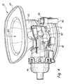
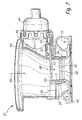
- FIG. 3 the housing of an exhaust gas turbocharger with mounted air guide device
- FIG. 4 a switchable air guide device with actuator and push rod in a perspective side view
- FIG. 5 a switchable air guide device without actuator in a perspective side view
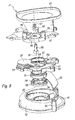
- FIG. 6 an exploded perspective view of the air duct device with parts
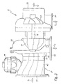
- FIG. 7 a sectional view along the longitudinal axis through the air guide device
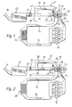
- FIG. 8 a perspective view of the upper housing part in the switching position "power channel open"
- FIG. 9 a perspective view of the upper housing part in the switching position "power channel closed”.
- Fig. 1 shows a schematic diagram of a trained in the present embodiment as a four-cylinder diesel engine
- Internal combustion engine 10 with an exhaust gas turbocharger 12 which comprises a compressor 13 in an intake tract 14 and a non-rotatably connected via a shaft 16 with the compressor 13 exhaust gas turbine 18 in an exhaust tract 20.
- the internal combustion engine 10 is designed as a gasoline engine with stratified direct injection.
- the guided through the exhaust system 20 exhaust gases of the internal combustion engine 10 drive via the exhaust gas turbine 18 to the compressor 13, which in turn pre-compressed the guided through the intake air flow 14.
- the compressor 13 of the exhaust gas turbocharger 12 is in the intake 14 an incorporated in a housing 19 air guide device 21 upstream, by means of which the compressor 13 is inflict on at least two different ways with the air flow and their operation will be explained in more detail below.
- the air flow is finally passed through a known intercooler 26, by means of which the heated by the compressor 13, precompressed air is cooled before entering the internal combustion engine 10.
- the arrows la and Ib indicate the direction of flow of the air flow in the intake tract 14, the arrows Ic and Id the direction of flow of the resulting combustion within the internal combustion engine 10 exhaust gases in the exhaust system 20.
- the sucked into the intake 14 air flow is first cleaned by means of an air filter 22 , Subsequently, via a downstream of the air filter 22 air mass meter 24, which is presently designed as H thoroughlyfiluuftmassenmesser, the mass of the air flow to control the subsequent combustion process determined.
- the air mass meter 24 may optionally provide important control variables for an exhaust gas recirculation system (not shown).
- the compressor 13 of the exhaust gas turbocharger 12 upstream air guide device 21 comprises a swirl duct 28, a power channel 30 and a pivotable switching flap 32, by means of which the air flow between the swirl duct 28 and the power channel 30 can be divided.
- the switching flap 32 is arranged as close as possible to the compressor 13 in order to minimize the volume between the compressor 13 and the switching flap 32 and thus the volume within which an angular momentum component of the air stream could weaken undesirably.
- the switching flap 32 completely closes the power duct 30 in the swirling position of the air guiding device 21 shown, so that the air flow is directed exclusively through the swirl duct 28 according to arrow W. Alternatively, however, it can also be provided that a part of the air flow is additionally conducted according to arrow L through the power channel 30.
- the air flow is evenly distributed to an air guide element 34, which is arranged at the end of the swirl duct 28 and consists of several, applied to a circular ring 36 vanes 38 (S. Fig.
- the air flow is given a rotational momentum component which is arranged parallel to an angular momentum of the compressor 13.
- a swirling air flow is generated, by means of which the compressor 13 is supplied with a strong Mitdrall, so that a driving impulsive force exerted on the compressor 13 and the speed of the compressor 13 is increased accordingly.
- the compressor 13 during load change into the full-load operating mode of the internal combustion engine 10 (s. Fig. 2 ) are not first accelerated back to the required rated speed, so that a quick response of the internal combustion engine 10 is ensured.
- a particularly large increase in speed can be achieved that the compressor 13 is impressed by the air flow such a strong Mitdrall that the compressor 13 operates in part-load operating mode of the internal combustion engine 10 as a so-called cold air turbine or impulse turbine.
- Fig. 2 shows a schematic diagram of the internal combustion engine 10 according to Fig. 1 , wherein the air guide device 21 is switched to a power position in which the switching flap 32 completely releases both the spinal canal 28 and the power channel 30.
- the switching operation between the swirl and the power position takes place during the load change of the internal combustion engine 10 between the part-load and the full-load operating mode. Since the compressor 13 in the full load operating mode To avoid a reduction in performance of the internal combustion engine 10 must be supplied with swirl-free air flow as possible, at least the majority of the air flow in the power position according to arrow L passed through the power channel 30 and flows the compressor 13 twist-free or macroscopically without parallel to an angular momentum of Compressor 13 arranged angular momentum component.
- Fig. 3 shows in a schematic representation of the housing of an exhaust gas turbocharger 12 with an attached switchable air guide device 21.
- the guided through the exhaust tract 20 exhaust gases of the internal combustion engine 10 drive via the exhaust gas turbine 18 to the compressor 13, which then precompressed by the intake 14 directed air flow.
- the compressor 13 of the exhaust gas turbocharger 12 is in the intake 14 an incorporated in a housing 19 air guide device 21 upstream, by means of which the compressor 13 can be flowed in at least two different ways with the air flow and their structure will be explained in more detail below. Shown are the inflow direction into the turbine side Ic and the turbine-side outflow direction Id and inflow Ie in the air guide device 21 and outflow Ia from the compressor.
- the air guiding device 21 is connected to the connecting line 45 with the clean air line 23. This connection can be made with coupling means familiar to the person skilled in the art, such as bayonet locks, hose clamps, Henn coupling or the like.
- the air guiding device 21 is fixedly connected to the compressor housing 50. In the illustrated embodiment, a portion of the air guide device 21 forms part of the compressor housing 50.
- the air compressed via the compressor wheel 51 flows out of the compressor outlet 52 via a charge air cooler 26 into the combustion chamber of the internal combustion engine 10.
- the compressor wheel 51 is moved by a shaft 16 from the turbine wheel 53 driven on the exhaust side of the exhaust gas turbocharger 12. On the turbine side with the Turbine inlet opening 54, the exhaust gas flows past the turbine wheel 53 to the turbine outlet 55th
- Fig. 4 shows a perspective view of a multi-part housing, in this case made of plastic, a switchable air guide device 21, consisting of an upper part 40 and a lower part 46 with a middle part arranged therebetween 41.
- the sucked by the exhaust gas turbocharger 12 air flows through the air inlet 68 on the clean air side connecting flange 45 in the air guiding device 21 a.
- a mounted on the upper part 40 of the air guide device actuator 44 is connected via a push rod 61 and a lever 62 to the switching device 32. Shown is a vacuum actuator 44 which is controlled via a switching valve (not shown).
- Fig. 5 shows the perspective view of a switchable air guide device 21 without the representation of the actuator 44.
- the upper part 40 is fixedly connected to the middle part 41 and the lower part 46 via a number of attachment points 64.
- the clean air enters from the air filter 22 via the air inlet 60 on the clean air line 23 corresponding connecting flange 45 in the air guide device 21 and after the compression of the air in the compressor 13, this flows out of the compressor outlet 52.
- the flange at the compressor outlet 52 is formed by the lower part 46, which is connected to the compressor housing 50 of the exhaust gas turbocharger 12.
- a sealing ring (not shown) or other suitable sealing means, such as a liquid seal is provided.
- the shift lever 62 shown is provided with a ball head to allow optimum mobility of the push rod 61 on the shift lever 62.
- a housing-fixed stop surface 65 limits the angle of rotation of the shift lever 62 and thus the pivoting flap 32 in the direction of "power channel open".
- Fig. 6 shows an exploded perspective view of the Fig. 4
- the upper part 40 forms the connecting flange 45 to the clean air line 23 and the attachment points 76 for fixing an actuator 44.
- the shaft 66 is mounted for transmitting the forces of the actuator 44 to the switching device 32 in the upper part 40.
- This shaft 66 connects the switching device 32 with the shift lever 62. This may be connected by a screw 67 or other method with the shaft.
- a pivoting flap 32 is arranged, which can close and open the power channel inlet 68 by a rotation about the pivot axis III, while the spinal canal inlet 69 remains constantly open.
- a tribologically optimized sliding ring 42 is arranged, which allows a slight movement of the pivoting flap 32 over the edge of the power channel inlet 68.
- through-holes 70 are arranged on the circumference 41 on the circumference, which allow a screwing of the central part 41 between the upper part 40 and the lower part 46.
- Adjoining the middle part 41, the lower part 46, which forms part of the compressor housing 50, between a spacer ring 71 and a Strömungsleitgitter 34 is inserted.
- the Strömungsleitgitter 34 consists of a circular ring 36 with attached guide vanes 38.
- the lower part 46 forms near the middle part 41 predominantly the spinal canal 28 and partially the Verêtrvolute 72 and the fastening device 64 for middle part 41 and upper part 40 from.
- the lower part 46 is fixedly connected to the compressor housing 50.
- Fig. 7 is a sectional view of the air guide device 21 according to FIG. 2 along the longitudinal axis of the power channel 30.
- the filtered clean air flows at the air inlet 60 in the funnel-shaped upper part 40, which is connected via the connecting flange 45 with the clean air line 23 (not shown), in the air guide device 21 a.
- Fixed to the upper part 40 is the actuator 44, which actuates the pivoting flap 32.
- the central portion 41 forms the main flow direction of the power channel 30 and around the power channel 30 spiral around vortex channel 28.
- the vortex channel 28 is designed as a flow volume and allows the air to flow transversely to the main flow direction between the guide vanes 38 of the Strömungsleitgitters 34 tangentially into the power channel 30.
- the division of the air flow into two partial flows, into the swirl duct 28 and the power duct 30, takes place through the design of the middle part 41, which separates the air inlet swirl duct 69 from the air inlet power duct 68 by the housing shape.
- the pivoting flap 32 is movably mounted. In the area outside the air inlet power channel 68, the pivoting flap 32 through the slideways 73 in the upper part 40 and central part 41 supported.
- the air inlet power channel 68 can be partially or completely closed by the pivoting flap 32.
- the inlet opening power channel 68 is preset on a sliding disk 42, on which the pivoting flap 32 rests.
- a spacer 71 and the Strömungsleitgitter 34 are inserted, which together form a portion of the power channel 30 and are held by heels between the middle part 41 and lower part 46.
- the power channel 30 merges in the lower part 46 into the volute of the compressor housing 50, which is formed in part by the lower part 46.
- Fig. 8 shows a perspective bottom view of the upper part 40 with the pivoting flap 32 in the switching position "power channel open” (actuator not shown).
- the cross-sectional opening 74 for the air to flow into the inlet power channel 68 and the entrance swirl duct 69 are completely open.
- the pivoting flap 32 bears against a stop surface 75 and is supported on the slide tracks 73.
- the torque of the switching shaft 66 is transmitted via a flat edge on the pivoting flap 32.
- Fig. 9 shows a bottom perspective view of the upper part 40 with the pivoting flap 32 in the switching position "power channel closed” (actuator not shown).
- the shift lever 62 abuts against the abutment surface 65.
- the cross-sectional opening 74 for the air to Inflow into the inlet power channel 68 and the entrance swirl duct 69 is partially closed, so that the pivoting flap 32 completely closes the air inlet power channel 68 in the middle part 41 while the air inlet swirl duct 69 remains free.
Abstract
Description
Die Erfindung betrifft einen Abgasturbolader für eine Brennkraftmaschine, der im Oberbegriff des Patentanspruchs 1 angegebenen Art sowie eine schaltbare Luftführungsvorrichtung eines Abgasturboladers.The invention relates to an exhaust gas turbocharger for an internal combustion engine, the type specified in the preamble of patent claim 1 and a switchable air guide device of an exhaust gas turbocharger.
Ein derartiger Abgasturbolader ist bereits aus dem Serienfahrzeugbau bekannt und umfasst üblicherweise einen in einem Ansaugtrakt einer Brennkraftmaschine anordnenbaren Verdichter zum Vorverdichtet eines Luftstroms, welcher durch den Ansaugtrakt auf den Verdichter zu leitenden ist. Der Verdichter übernimmt dabei das Ansaugen des Luftstroms und fördert den vorverdichteten Luftstrom weiter zur Brennkraftmaschine. Die Antriebsleistung des Verdichters wird durch eine in einem Abgastrakt der Brennkraftmaschine angeordnete und über eine Welle drehfest mit dem Verdichter gekoppelte Abgasturbine geliefert, welche durch die Abgase der Brennkraftmaschine angetrieben wird. Der vom Verdichter vorverdichtete und aufgeheizte Luftstrom wird vor dem Eintritt in die Zylinder der Brennkraftmaschine mit Hilfe eines Ladeluftkühlers gekühlt, um eine verbesserte Zylinderfüllung zu erzielen.Such an exhaust-gas turbocharger is already known from series-production vehicle construction and usually comprises a compressor, which can be arranged in an intake tract of an internal combustion engine, for precompressed air flow, which is to be conducted through the intake tract to the compressor. The compressor takes over the suction of the air flow and promotes the pre-compressed air flow to the engine. The drive power of the compressor is supplied by a arranged in an exhaust tract of the internal combustion engine and a shaft rotatably coupled to the compressor exhaust gas turbine, which is driven by the exhaust gases of the internal combustion engine. The pre-compressed and heated by the compressor air flow is cooled before entering the cylinders of the internal combustion engine by means of a charge air cooler in order to achieve improved cylinder filling.
Als nachteilig an den bekannten Abgasturboladern ist dabei jedoch der Umstand anzusehen, dass es aufgrund der Massenträgheit des Verdichters bei dynamischen Lastwechselvorgängen der Brennkraftmaschine, beispielsweise beim Wechsel vom Teillast in den Vollast-Betriebsmodus, zum sogenannten Turboloch kommt, da der Verdichter erst wieder auf die geforderte Nenndrehzahl beschleunigt werden muss, um den gewünschten Ladedruck bereitstellen zu können.However, the fact that it is due to the inertia of the Compressor in dynamic load changes of the internal combustion engine, for example when changing from part load in the full load operating mode, the so-called turbo lag comes because the compressor must be accelerated again to the required rated speed to provide the desired boost pressure can.
Aufgabe der vorliegenden Erfindung ist es, einen Abgasturbolader sowie eine schaltbare Luftführungsvorrichtung für einen Abgasturbolader zu schaffen, welche ein verbessertes Ansprechverhalten einer Brennkraftmaschine ermöglichen.Object of the present invention is to provide an exhaust gas turbocharger and a switchable air ducting device for an exhaust gas turbocharger, which allow an improved response of an internal combustion engine.
Die Aufgabe wird erfindungsgemäß durch eine schaltbare Luftführungsvorrichtung für einen Abgasturbolader für eine Brennkraftmaschine mit den Merkmalen des Patentanspruchs 1 gelöst. Vorteilhafte Ausgestaltungen mit zweckmäßigen und nicht-trivialen Weiterbildungen der Erfindung sind in den jeweiligen Unteransprüchen angegeben.The object is achieved by a switchable air guide device for an exhaust gas turbocharger for an internal combustion engine with the features of claim 1. Advantageous embodiments with expedient and non-trivial developments of the invention are specified in the respective subclaims.
Erfindungsgemäß wird ein verbessertes Ansprechverhalten einer Brennkraftmaschine dadurch ermöglicht, dass dem Verdichter eine schaltbare Luftführungsvorrichtung in Modulbauweise aus mehreren Komponenten vorgeordnet ist, mittels welcher der Verdichter auf zumindest zwei unterschiedliche Weisen mit dem Luftstrom anzuströmen ist. Mit anderen Worten ist vorgesehen, dass die Anströmbedingungen des Verdichters mit Hilfe der Luftführungsvorrichtung variiert werden können, wodurch es im Gegensatz zum Stand der Technik möglich ist, den Luftstrom beispielsweise im Teillast- und im Vollast-Betriebsmodus jeweils unterschiedlich auf den Verdichter zu leiten. Die Möglichkeit einer variablen Anströmung des Verdichters erlaubt daher eine verbesserte Berücksichtigung des jeweiligen Betriebsmodus der Brennkraftmaschine, woraus ein entsprechend verbessertes Ansprechverhalten derselben resultiert. Durch eine anpassbare Anströmungen des Verdichters kann dessen Drehzahl beispielsweise im Teillast Betriebsmodus angehoben werden, so dass sich beim dynamischen Lastwechsel vom Teillast- in den Vollast-Betriebsmodus die zum Beschleunigen des Verdichters auf die geforderte Nenndrehzahl benötigte Zeitspanne entsprechend verkürzt bzw. die geforderte Nenndrehzahl bereits anliegt.According to the invention an improved response of an internal combustion engine is made possible by the fact that the compressor is preceded by a switchable air ducting device in modular construction of several components, by means of which the compressor is to flow in at least two different ways with the air flow. In other words, it is provided that the flow conditions of the Compressor can be varied with the help of the air guide device, whereby it is possible in contrast to the prior art, the air flow, for example, in the part-load and full-load operating mode each differently to the compressor. The possibility of a variable flow of the compressor therefore allows an improved consideration of the respective operating mode of the internal combustion engine, resulting in a correspondingly improved response of the same results. By an adaptable flow to the compressor whose speed can be raised, for example, in part load operating mode, so that the time required to accelerate the compressor to the required rated speed correspondingly shortened during dynamic load change from part load to full load operating mode or the required rated speed is already applied ,
In einer vorteilhaften Ausgestaltung der Erfindung ist vorgesehen, dass die Luftführungsvorrichtung zwischen einer Wirbelstellung, in welcher dem Luftstrom vor dem Anströmen des Verdichters eine Drehimpulskomponente zu verleihen ist, und einer Leistungsstellung, in welcher der Verdichter mit einem zumindest im Wesentlichen drehimpulsfreien Luftstrom anzuströmen ist, zu schalten ist. In der Wirbelstellung kann somit die Drehzahl des Verdichters beispielsweise unter Teillast durch Veränderung der Anströmbedingungen erhöht werden, ohne dass externe Energie - beispielsweise mittels eines elektrischen Unterstützers - eingebracht werden müsste. Ist die Luftführungsvorrichtung in Wirbelstellung geschaltet, nimmt der Verdichter somit weniger Leistung auf, wodurch ein größerer Teil der von der Abgasturbine eingespeisten Leistung zur Überwindung von Lagerreibungskräften genutzt und die Drehzahl des Verdichters entsprechend angehoben werden kann. Im Idealfall entspricht die auf diese Weise erreichbare Drehzahl der geforderten Nenndrehzahl, so dass ein zumindest annähernd "drehzahistationärer" Betrieb des Verdichters erreichbar ist. Umgekehrt kann ein Schalten der Luftführungsvorrichtung in die Leistungsstellung dazu genutzt werden, den Verdichter mit einem zumindest im Wesentlichen drehimpulsfreien Luftstrom anzuströmen, um etwa im Vollast Betriebsmodus der Brennkraftmaschine keine Leistungsminderung zu erhalten.In an advantageous embodiment of the invention, it is provided that the air guiding device between a swirl position, in which the air flow before the flow of the compressor is to impart a Drehimpulskomponente, and a power position in which the compressor is fed with an at least substantially rotationally impulsive air flow to switch is. In the swirl position thus the speed of the compressor can be increased, for example under partial load by changing the Anströmbedingungen without external energy - for example by means of an electric Supporters - would have to be introduced. If the air guiding device is connected in a swirling position, the compressor thus absorbs less power, whereby a greater part of the power fed in by the exhaust gas turbine can be used to overcome bearing friction forces and the rotational speed of the compressor can be increased accordingly. Ideally, the achievable in this way speed corresponds to the required rated speed, so that at least approximately "drehzahistationärer" operation of the compressor can be achieved. Conversely, a switching of the air guiding device in the power position can be used to flow the compressor with an at least substantially rotationally impulsive air flow, in order to obtain no reduction in performance, for example in the full-load operating mode of the internal combustion engine.
Dabei hat es sich in weiterer Ausgestaltung als vorteilhaft gezeigt, dass bei in die Wirbelstellung geschalteter Luftführungsvorrichtung die dem Luftstrom zu verleihende Drehimpulskomponente parallel zu einem Drehimpuls des Verdichters angeordnet ist. Dies ermöglicht eine besonders vorteilhafte Anströmung des Verdichters, da der Luftstrom auf diese Weise gleichsinnig mit einer Drehrichtung des Verdichters verwirbelt ist und aufgrund der starken Mitdrallströmung ein entsprechend hohes Drehmoment auf den Verdichter übertragen kann. Dies ermöglicht eine erhebliche Steigerung der Drehzahl des Verdichters, welcher somit beispielsweise im Teillast-Betriebsmodus als sogenannte Kaltluftturbine bzw. Impulsturbine arbeiten kann.It has been found in a further embodiment to be advantageous that when switched to the fluidized air guide device, the air flow to be imparted angular momentum component is arranged parallel to an angular momentum of the compressor. This allows a particularly advantageous flow to the compressor, since the air flow is swirled in this way in the same direction with a direction of rotation of the compressor and due to the strong Mitdrallströmung a correspondingly high torque can be transmitted to the compressor. This allows a significant increase in the speed of the compressor, which thus For example, in part-load operating mode can work as a so-called cold air turbine or impulse turbine.
In einer weiteren vorteilhaften Ausgestaltung der Erfindung ist vorgesehen, dass die Luftführungsvorrichtung zumindest einen Wirbelkanal und einen Leistungskanal umfasst, wobei der Luftstrom in der Wirbelstellung zumindest überwiegend durch den Wirbelkanal und in der Leistungsstellung zumindest überwiegend durch den Leistungskanal zu leiten ist. Dies stellt eine konstruktiv einfache und kostengünstige Möglichkeit dar, den Verdichter auf zumindest zwei unterschiedliche Weisen mit dem Luftstrom anzuströmen.In a further advantageous embodiment of the invention, it is provided that the air-guiding device comprises at least one spinal canal and one power canal, wherein the air flow in the fluidized position is to be guided at least predominantly through the spinal canal and in the power position at least predominantly through the power canal. This is a structurally simple and cost-effective way to inflate the compressor in at least two different ways with the air flow.
Ein weiterer Vorteil ergibt sich daraus, dass die Luftführungsvorrichtung eine Schaltklappe umfasst, mittels welcher ein Anteil des durch den Wirbelkanal und/oder durch den Leistungskanal zu leitenden Luftstroms einzustellen ist. Eine derartige Schaltklappe erlaubt ein schnelles Schalten der Luftführungsvorrichtung und kann einfach und bauraumsparend in die Luftführungsvorrichtung integriert werden. Der mittels der Schaltklappe einstellbare Anteil des Luftstroms ist dabei vorzugsweise ein Massenanteil. Dabei kann es auch vorgesehen sein, dass mittels der Schaltklappe der gesamte Luftstrom entweder durch den Wirbelkanal oder durch den Leistungskanal zu leiten ist. Die Schaltklappe sollte dabei vorteilhafterweise Schaltzeiten unter 100 ms aufweisen, um ein schnelles Ansprechen auf Lastwechselvorgänge der Brennkraftmaschine sicherzustellen.A further advantage results from the fact that the air guiding device comprises a switching flap by means of which a portion of the air flow to be conducted through the swirl duct and / or through the power duct is to be set. Such a switching flap allows rapid switching of the air guide device and can be integrated easily and space-saving in the air guide device. The adjustable by means of the switching flap portion of the air flow is preferably a mass fraction. It can also be provided that by means of the switching flap, the entire air flow is to be conducted either through the vortex channel or through the power channel. The switching flap should advantageously have switching times of less than 100 ms in order to achieve a fast To ensure response to load changes of the internal combustion engine.
Ein weiterer Vorteil der Schaltklappe besteht darin, dass der angesaugte Luftstrom gezielt angedrosselt werden kann, wodurch eine Steuerung von Abgasrückführungsraten der Brennkraftmaschine ermöglicht sind. Des Weiteren kann durch gezielte Androsselung mit Hilfe der Schaltklappe der Wirkungsgrad der Brennkraftmaschine verschlechtert werden, wodurch die Temperatur der Abgase steigt. Dieser Effekt kann dann beispielsweise zur Verbesserung der Emissionswerte beim Kaltstart oder bei als Dieselmotoren ausgebildeten Brennkraftmaschinen zur Regeneration eines Dieselpartikelfilters bzw. eines NO-Speicherkatalysators verwendet werden.Another advantage of the switching flap is that the sucked air flow can be throttled specifically, whereby a control of exhaust gas recirculation rates of the internal combustion engine are possible. Furthermore, the efficiency of the internal combustion engine can be worsened by targeted throttling with the aid of the switching flap, whereby the temperature of the exhaust gases increases. This effect can then be used, for example, to improve the emission values during cold start or in internal combustion engines designed as diesel engines for the regeneration of a diesel particulate filter or a NO storage catalytic converter.
Damit der Verdichter beim Bewegen der Schaltklappe nicht durch Druckimpulse geschädigt wird, hat es sich in weiterer Ausgestaltung als vorteilhaft gezeigt, dass die Schaltklappe radial gegenüber dem Leistungskanal verschwenkbar ist und die Klappe sehr nah am Verdichterrad angeordnet ist, um ein möglichst kleines Volumen zwischen der geschossenen Klappe und dem Verdichterrad zu erreichen.Thus, the compressor is not damaged by pressure pulses when moving the switching flap, it has been found to be advantageous in another embodiment that the switching flap is pivotable radially relative to the power channel and the flap is located very close to the compressor to the smallest possible volume between the shot To reach the flap and the compressor wheel.
Die Schaltklappe sollte ein geringes Gewicht haben und kann als dünne Scheibe ausgeführt sein, die seitlich aus einem Hohlraum in etwa senkrecht zum Leistungskanal in die Strömung einschwenkt. Vorteilhaft ist eine Lagerung der Klappe in dem dem Verdichter abgewandten Gehäuseteil der Luftführungsvorrichtung, da niedrigere Temperaturen zu erwarten sind. Die Klappenlagerung kann aber auch in einem andern Gehäuseteil integriert sein. Zur Führung der Schaltklappe während der Betätigung und zur Reduzierung der Reibkräfte werden durch das Gehäuse Gleitschienen gebildet, an denen sich die Klappe entlang bewegen kann.The switching flap should have a low weight and can be designed as a thin disc which pivots laterally out of a cavity approximately perpendicular to the power channel in the flow. Advantageously, a storage of the flap in the compressor facing away Housing part of the air guide device, since lower temperatures are expected. The flap bearing can also be integrated in another housing part. To guide the switching flap during actuation and to reduce the frictional forces are formed by the housing slide rails on which the flap can move along.
Um eine definierte Position der Schaltklappe in den Endlagen zu gewährleisten und akustische Beeinträchtigungen während der Ruhestellung in diesen Endlagen zu erreichen, sind Endanschläge für den Schaltmechanismus im Gehäuse der Luftführungsvorrichtung vorgesehen.In order to ensure a defined position of the switching flap in the end positions and to achieve acoustic interference during the rest position in these end positions, end stops for the switching mechanism are provided in the housing of the air guiding device.
In einer vorteilhaften Ausgestaltung ist ein Endanschlag für die Klappe in der Stellung "Leistungskanal offen" auf der Gehäuseinnenseite angeordnet, da in dieser Position die Klappe mit einem Teil ihrer Seitenfläche gegen den Anschlag gedrückt werden kann und Schaltmechanismus durch den Aktuator unter Spannung gehalten wird und somit eine Geräuschbildung durch Klappern von Schaltmechanismus oder Klappe verhindert werden kann. Ein zweiter Endanschlag ist für den Mitnehmer außerhalb des Gehäuses für die Schaltstellung "Leistungskanal geschlossen" vorgesehen. In dieser Endlage legt sich die Klappe am Dichtring an, da der Verdichter einen Unterdruck erzeugt, der die Klappe auf die Dichtung zieht und der Hebel zur Betätigung der Klappe ist am Endanschlag verspannt.In an advantageous embodiment, an end stop for the flap in the "power channel open" position is arranged on the inside of the housing, since in this position the flap can be pressed with part of its side surface against the stop and switching mechanism is held by the actuator under tension and thus Noise can be prevented by rattling of switching mechanism or flap. A second end stop is provided for the driver outside the housing for the switching position "power channel closed". In this end position, the flap applies to the sealing ring, since the compressor generates a negative pressure, which pulls the flap on the seal and the lever for actuating the flap is clamped to the end stop.
Um eine leichte Beweglichkeit der Klappe beim Schalten zu ermöglichen und eine dichtende Anlage an die Dichtscheibe für den geschlossenen Zustand zu erreichen, ist die Schaltklappe in Richtung der Schwenkachse verschiebbar gelagert oder als Bauteil so nachgiebig, dass eine Anlage an der Dichtscheibe und ein Gleiten minimal versetzt in Richtung der Schwenkachse in die Stellung "Leistungskanal" möglich ist.In order to allow easy movement of the flap when switching and to achieve a sealing engagement with the sealing disc for the closed state, the switching flap is slidably mounted in the direction of the pivot axis or as a component so yielding that a contact with the sealing disc and a sliding minimally offset in the direction of the pivot axis in the position "power channel" is possible.
Eine solche Verschiebung der Klappenlage in Richtung der Schwenkachse kann durch ein axiales Lagerspiel oder eine spezielle Gestaltung der Schaltklappe erreicht werden, wenn beispielsweise die Klappenfläche über einen federnden Steg mit der Lagerstelle verbunden ist. Die Schaltklappe kann in verschiedener Weise betätigt werden. Für die Schaltung der Klappe kommen pneumatische Aktuatoren wie Unter- oder Überdruckdosen oder elektrische Antriebe in Betracht. Es ist auch möglich, die Schaltklappe magnetisch zu betätigen. Der Aktuator ist zweckmäßiger Weise an einem der Gehäuseteile der Luftführungsvorrichtung befestigt. Vorteilhaft ist die Montage an dem Gehäuseteil, das die Lagerung der Schaltklappe bildet, um unnötige Toleranzen zu vermeiden. In der Schaltstellung "Leistungskanal geschlossen" wird durch den Staudruck der Luft in der Luftführungsvorrichtung die Klappe in Richtung Verdichter gegen die den Öffnungsquerschnitt des Leistungskanals umgebene Dichtscheibe gedrückt und so die Dichtwirkung verstärkt. Um die Stellkräfte für den Aktuator möglichst klein zu halten, besteht die Dichtscheibe vorzugsweise aus einem gleitoptimierten Material oder weist zumindest eine Oberfläche mit geringer Reibung auf. Ein möglicher Werkstoff zur tribologischen Optimierung ist beispielsweise Teflon. Ein Strömungsleitgitter zur Einleitung der Luft aus dem Wirbelkanal in den Leistungskanal kann zwischen der Klappe und dem Verdichter angeordnet sein. In einer vorteilhaften Ausgestaltung der Luftführungsvorrichtung ist das Strömungsleitgitter in das Unterteil oder das Verdichtergehäuse eingelegt und mit einem zusätzlichen Distanzring zum korrespondierenden Gehäuseteil fest gehalten. In einer anderen Ausführungsform der Luftführungsvorrichtung kann diese bei günstiger Ausgestaltung des Wirbelkanals ohne Strömungsleitgitter ausgeführt sein.Such a displacement of the flap position in the direction of the pivot axis can be achieved by an axial bearing clearance or a special design of the switching flap, for example, if the flap surface is connected via a resilient web to the bearing point. The switching flap can be operated in various ways. For the switching of the flap are pneumatic actuators such as under or over-pressure or electric drives into consideration. It is also possible to actuate the switching flap magnetically. The actuator is suitably attached to one of the housing parts of the air guiding device. It is advantageous to mount on the housing part, which forms the storage of the switching flap to avoid unnecessary tolerances. In the switch position "power duct closed", the damper in the direction of the compressor is pressed against the opening cross-section of the power duct surrounded sealing disk by the back pressure of the air in the air ducting device and thus increases the sealing effect. To the rest of the power for the To keep the actuator as small as possible, the sealing washer is preferably made of a slid-optimized material or has at least one surface with low friction. One possible material for tribological optimization is, for example, Teflon. A Strömungsleitgitter for introducing the air from the vortex channel in the power channel can be arranged between the flap and the compressor. In an advantageous embodiment of the air guiding device, the Strömungsleitgitter is inserted into the lower part or the compressor housing and held firmly with an additional spacer ring to the corresponding housing part. In another embodiment of the air guiding device, it can be designed with a favorable embodiment of the swirl duct without Strömungsleitgitter.
In einer weiteren vorteilhaften Ausgestaltung der Erfindung ist vorgesehen, dass die Luttführungsvorrichtung ein Luftleitelement, insbesondere ein Leitgitter, umfasst, mittels welchem eine Strömungsrichtung des Luftstroms umzulenken und/oder dem Luftstrom vor dem Anströmen des Verdichters die Drehimpulskomponente zu verleihen ist. Mit Hilfe eines derartigen Luftleitelements kann die Strömungsrichtung des Luftstroms besonders einfach und variabel umgelenkt und beispielsweise mit der Drehimpulskomponente versehen werden. Je nach Auslegung kann das Luftleitelement zu diesem Zweck eine oder mehrere Leitschaufeln mit variierbaren Schaufelprofilierungen bzw. Schaufelwinkelen oder unterschiedliche Durchströmungsquerschnitte aufweisen und ist somit optimal an die jeweiligen konstruktiven und strömungstechnischen Gegebenheiten anpassbar. Dabei kann die Luftführungsvorrichtung besonders bauraumsparend ausgebildet werden, indem der Wirbelkanal an einem Außenumfang des Leistungskanals angeordnet ist.In a further advantageous embodiment of the invention, it is provided that the Luttführungsvorrichtung an air guide element, in particular a guide grating comprises, by means of which deflect a flow direction of the air flow and / or the air flow is to impart the angular momentum component before the flow of the compressor. With the help of such a spoiler, the flow direction of the air flow can be particularly easily and variably deflected and provided, for example with the angular momentum component. Depending on the design, the air guide element for this purpose one or more vanes with variable blade profiles or blade angles or have different flow cross-sections and is thus optimally adapted to the respective structural and fluidic conditions. In this case, the air-guiding device can be designed to save space in a particularly space-saving manner by arranging the swirl duct on an outer circumference of the power duct.
In weiterer Ausgestaltung hat es sich zudem als vorteilhaft gezeigt, dass der Wirbelkanal zumindest abschnittsweise spiralförmig ausgebildet ist. Dies stellt eine konstruktiv einfache Möglichkeit dar, den Wirbelkanal als Strömungsvolute ausbilden und zur gezielten Umlenkung des Luftstroms verwenden zu können.In a further embodiment, it has also been found to be advantageous that the vertebral channel is at least partially formed spirally. This represents a structurally simple way to form the vortex channel as flow volutes and to use for targeted deflection of the air flow.
In einer weiteren vorteilhaften Ausgestaltung der Erfindung ist vorgesehen, dass die Luftführungsvorrichtung mechanisch, insbesondere mittels einer Über- und/oder Unterdruckdose, und/oder elektronisch zu schalten ist. Dies erlaubt eine besonders variable Ausgestaltung des Abgasturboladers und eine einfache Anpassbarkeit an unterschiedliche konstruktive Gegebenheiten, Ausstattungslinien oder dergleichen.In a further advantageous embodiment of the invention, it is provided that the air guide device is mechanically, in particular by means of an over- and / or vacuum unit, and / or to switch electronically. This allows a particularly variable embodiment of the exhaust gas turbocharger and a simple adaptability to different structural conditions, equipment lines or the like.
Weitere Vorteile ergeben sich dadurch, dass der Luftführungsvorrichtung ein Gehäuse zugeordnet ist, über welches die Luftführungsvorrichtung mit dem Abgasturbolader und/oder dem Ansaugtrakt koppelbar ist. Obwohl die Luftführungsvorrichtung grundsätzlich auch in ein ohnehin vorhandenes Verdichtergehäuse des Abgasturboladers integriert sein kann, bietet ein derartiges Gehäuse den Vorteil, dass die Luftführungsvorrichtung als selbständiges Bauteil ausgebildet sein und somit einfach mit bereits vorhandenen Abgasturboladern gekoppelt bzw. als Nachrüstlösung angeboten werden kann. Weiterhin wird aufgrund der variablen Ausgestaltungsmöglichkeiten der Luftführungsvorrichtung eine Senkung der Lagerhaltungskosten sowie der Wartungs- und Reparaturkosten erreicht. Die einzelnen Bauteile können auf verschiedene Weisen verbunden sein. Eine Ausführungsform ist die Montage mit Schrauben. Es sind aber auch andere Verfahren, wie beispielsweise Schweißen, Clipsen oder Kleben möglich. Zur Herstellung der Gehäusebauteile der Luftführungsvorrichtung 21 sind verschiedene Materialien denkbar. Üblicherweise werden die Gehäuse von Verdichtern aus einem Metallwerkstoff gefertigt. Die Luftführungsvorrichtung kann aber auch aus temperaturbeständigem Kunststoff gefertigt sein, beispielsweise Polyamid oder anderen technischen Kunststoffen.Further advantages result from the fact that the air guiding device is associated with a housing, via which the air guiding device can be coupled to the exhaust gas turbocharger and / or the intake tract. Although the air guiding device can in principle also be integrated into an already existing compressor housing of the exhaust gas turbocharger, such a housing offers the advantage that the Air guiding device may be formed as an independent component and thus easily coupled with existing exhaust gas turbochargers or offered as a retrofit solution. Furthermore, a reduction of storage costs and maintenance and repair costs is achieved due to the variable design options of the air guide device. The individual components can be connected in various ways. One embodiment is the assembly with screws. But there are also other methods, such as welding, clipping or gluing possible. For the production of the housing components of the
Weitere Vorteile, Merkmale und Einzelheiten der Erfindung ergeben sich aus der nachfolgenden Beschreibung eines Ausführungsbeispiels sowie anhand der Zeichnungen, in welchen gleiche oder funktionsgleiche Elemente mit identischen Bezugszeichen versehen sind. Es zeigen:Further advantages, features and details of the invention will become apparent from the following description of an embodiment and with reference to the drawings, in which the same or functionally identical elements are provided with identical reference numerals. Show it:
Claims (11)
Applications Claiming Priority (1)
| Application Number | Priority Date | Filing Date | Title |
|---|---|---|---|
| DE102007058615A DE102007058615A1 (en) | 2007-12-04 | 2007-12-04 | Exhaust gas turbocharger for an internal combustion engine and device for switching an air guide device of an exhaust gas turbocharger |
Publications (3)
| Publication Number | Publication Date |
|---|---|
| EP2067958A2 true EP2067958A2 (en) | 2009-06-10 |
| EP2067958A3 EP2067958A3 (en) | 2009-11-25 |
| EP2067958B1 EP2067958B1 (en) | 2012-02-01 |
Family
ID=40430152
Family Applications (1)
| Application Number | Title | Priority Date | Filing Date |
|---|---|---|---|
| EP08170451A Not-in-force EP2067958B1 (en) | 2007-12-04 | 2008-12-02 | Exhaust gas turbocharger for a combustion engine and device to switch an air guidance device of an exhaust gas turbocharger |
Country Status (4)
| Country | Link |
|---|---|
| US (1) | US8156741B2 (en) |
| EP (1) | EP2067958B1 (en) |
| AT (1) | ATE543992T1 (en) |
| DE (1) | DE102007058615A1 (en) |
Cited By (1)
| Publication number | Priority date | Publication date | Assignee | Title |
|---|---|---|---|---|
| EP2682592A3 (en) * | 2012-07-06 | 2014-07-02 | Kabushiki Kaisha Toyota Jidoshokki | Intake air supply structures of turbo superchargers |
Families Citing this family (13)
| Publication number | Priority date | Publication date | Assignee | Title |
|---|---|---|---|---|
| US8177498B2 (en) * | 2009-04-21 | 2012-05-15 | Ford Global Technologies, Llc | Inlet swirl control for turbochargers |
| US8666634B2 (en) * | 2011-02-25 | 2014-03-04 | Bendix Commercial Vehicle Systems Llc | Method of operating a vehicle equipped with a pneumatic booster system |
| US8484971B2 (en) | 2011-02-25 | 2013-07-16 | Bendix Commercial Vehicle Systems Llc | Method of operating a vehicle equipped with a pneumatic booster system |
| US8468824B2 (en) * | 2011-02-25 | 2013-06-25 | Bendix Commercial Vehicle Systems Llc | Method of operating a vehicle equipped with a pneumatic booster system |
| US8505297B2 (en) * | 2011-02-25 | 2013-08-13 | Bendix Commercial Vehicle Systems Llc | Method of operating a vehicle equipped with a pneumatic booster system |
| US20120222643A1 (en) * | 2011-03-01 | 2012-09-06 | Mann+Hummel Gmbh | Swirl guiding acoustic device with an internal coaxially integrated swirl guide structure |
| US8820071B2 (en) * | 2011-07-20 | 2014-09-02 | GM Global Technology Operations LLC | Integrated compressor housing and inlet |
| DE102011111747A1 (en) * | 2011-08-24 | 2013-02-28 | Daimler Ag | Compressor for exhaust turbocharger of internal combustion engine, particularly gasoline engine of motor vehicle, particularly passenger car, comprises guide element arranged against air flow in axial direction of compressor wheel |
| DE102014217996A1 (en) * | 2014-09-09 | 2016-03-10 | Bayerische Motoren Werke Aktiengesellschaft | Exhaust gas turbocharger for an internal combustion engine and method for producing such a turbocharger |
| DE102015207573B4 (en) * | 2015-04-24 | 2023-07-06 | Ford Global Technologies, Llc | Internal combustion engine with combined exhaust aftertreatment system |
| US10844817B2 (en) * | 2018-04-23 | 2020-11-24 | Ford Global Technologies, Llc | Convolute-swirl integrated duct for swirl generation |
| US11208971B2 (en) * | 2019-01-16 | 2021-12-28 | Ford Global Technologies, Llc | Methods and systems for mitigating condensate formation |
| CN114877463A (en) * | 2022-04-27 | 2022-08-09 | 上海伯涵热能科技有限公司 | Door leaf with decorative electric air door |
Citations (5)
| Publication number | Priority date | Publication date | Assignee | Title |
|---|---|---|---|---|
| JPH116500A (en) * | 1997-06-17 | 1999-01-12 | Toyota Central Res & Dev Lab Inc | Swirl flow generating device for centrifugal compressor |
| EP1416123A2 (en) * | 2002-10-29 | 2004-05-06 | Bayerische Motoren Werke Aktiengesellschaft | Vortex inlet vanes |
| EP1482128A1 (en) * | 2003-05-28 | 2004-12-01 | Ford Global Technologies, LLC | Supercharged Internal combustion engine |
| WO2005100798A1 (en) * | 2004-04-13 | 2005-10-27 | Integral Powertrain Ltd | A pre-whirl generator, a compressor and a method of imparting pre-whirl to a gas flow |
| FR2878914A1 (en) * | 2004-12-03 | 2006-06-09 | Inst Francais Du Petrole | Air compressor for supercharged internal combustion engine, has butterfly valve moved between full open and close positions, and annular chamber, disposed around suction pipeline, to spin fresh air before its introduction in pipeline |
Family Cites Families (8)
| Publication number | Priority date | Publication date | Assignee | Title |
|---|---|---|---|---|
| US3232043A (en) * | 1964-01-13 | 1966-02-01 | Birmann Rudolph | Turbocompressor system |
| US3672786A (en) * | 1970-11-02 | 1972-06-27 | Carrier Corp | Capacity control mechanism for centrifugal gas compressors |
| FR2127393A5 (en) * | 1971-03-05 | 1972-10-13 | Constr Telephoniques | |
| US3922108A (en) * | 1974-03-18 | 1975-11-25 | Wallace Murray Corp | Pre-whirl turbo charger apparatus |
| US5025629A (en) * | 1989-03-20 | 1991-06-25 | Woollenweber William E | High pressure ratio turbocharger |
| US6328024B1 (en) * | 1999-03-30 | 2001-12-11 | Mark S. Kibort | Axial flow electric supercharger |
| US6994518B2 (en) * | 2002-11-13 | 2006-02-07 | Borgwarner Inc. | Pre-whirl generator for radial compressor |
| US7874789B2 (en) * | 2007-04-06 | 2011-01-25 | Honeywell International, Inc. | Compressor and compressor housing |
-
2007
- 2007-12-04 DE DE102007058615A patent/DE102007058615A1/en not_active Withdrawn
-
2008
- 2008-12-02 EP EP08170451A patent/EP2067958B1/en not_active Not-in-force
- 2008-12-02 AT AT08170451T patent/ATE543992T1/en active
- 2008-12-04 US US12/328,047 patent/US8156741B2/en not_active Expired - Fee Related
Patent Citations (5)
| Publication number | Priority date | Publication date | Assignee | Title |
|---|---|---|---|---|
| JPH116500A (en) * | 1997-06-17 | 1999-01-12 | Toyota Central Res & Dev Lab Inc | Swirl flow generating device for centrifugal compressor |
| EP1416123A2 (en) * | 2002-10-29 | 2004-05-06 | Bayerische Motoren Werke Aktiengesellschaft | Vortex inlet vanes |
| EP1482128A1 (en) * | 2003-05-28 | 2004-12-01 | Ford Global Technologies, LLC | Supercharged Internal combustion engine |
| WO2005100798A1 (en) * | 2004-04-13 | 2005-10-27 | Integral Powertrain Ltd | A pre-whirl generator, a compressor and a method of imparting pre-whirl to a gas flow |
| FR2878914A1 (en) * | 2004-12-03 | 2006-06-09 | Inst Francais Du Petrole | Air compressor for supercharged internal combustion engine, has butterfly valve moved between full open and close positions, and annular chamber, disposed around suction pipeline, to spin fresh air before its introduction in pipeline |
Cited By (1)
| Publication number | Priority date | Publication date | Assignee | Title |
|---|---|---|---|---|
| EP2682592A3 (en) * | 2012-07-06 | 2014-07-02 | Kabushiki Kaisha Toyota Jidoshokki | Intake air supply structures of turbo superchargers |
Also Published As
| Publication number | Publication date |
|---|---|
| ATE543992T1 (en) | 2012-02-15 |
| EP2067958A3 (en) | 2009-11-25 |
| DE102007058615A1 (en) | 2009-06-10 |
| US8156741B2 (en) | 2012-04-17 |
| EP2067958B1 (en) | 2012-02-01 |
| US20090139228A1 (en) | 2009-06-04 |
Similar Documents
| Publication | Publication Date | Title |
|---|---|---|
| EP2067958B1 (en) | Exhaust gas turbocharger for a combustion engine and device to switch an air guidance device of an exhaust gas turbocharger | |
| EP1274928B1 (en) | Turbocharger device for an internal combustion engine | |
| DE102010053951B4 (en) | Turbine for an exhaust gas turbocharger | |
| EP1639245B1 (en) | Internal combustion engine comprising a compressor in the suction part and method therefor | |
| WO2006007963A1 (en) | Compressor in an exhaust-gas turbocharger for an internal combustion engine and method for operating a compressor | |
| WO2008125381A1 (en) | Compressor housing and turbocharger | |
| EP2211048B1 (en) | Exhaust gas flap device and exhaust gas heat recovery system of a combustion engine | |
| EP2956657A1 (en) | Internal combustion engine comprising a booster | |
| WO2010069301A2 (en) | Fully variable turbine for exhaust gas turbocharger | |
| WO2019052729A1 (en) | Radial compressor comprising an iris diaphragm mechanism for a charging device of an internal combustion engine, charging device, and lamella for the iris diaphragm mechanism | |
| EP1546524B1 (en) | Device for compressing combustion air wit an integrated bypass device | |
| EP1881162B1 (en) | Turbocharger for internal combustion engines | |
| EP1762716B1 (en) | Exhaust brake with bypass channel | |
| WO2006076938A1 (en) | Vehicle comprising an exhaust gas recirculation system | |
| EP1530671B1 (en) | Exhaust gas turbocharger for an internal combustion engine | |
| DE102005062682A1 (en) | Compressor for e.g. petrol engine of motor vehicle, has secondary channel provided in blade region of blade of compressor wheel, and redirecting air from additional channel under by passing of diffuser channel into spiral channel | |
| EP1746263B1 (en) | Valve system for a heat exchanger | |
| DE102010020709A1 (en) | Control device for a turbo-charged internal combustion engine | |
| DE102010051777A1 (en) | Turbine for an exhaust gas turbocharger of an internal combustion engine | |
| DE102008060251B4 (en) | Exhaust gas turbocharger with variable turbine geometry | |
| WO2009071174A1 (en) | Exhaust gas turbocharger for an internal combustion engine and method for connecting an air conveyance device of an exhaust gas turbocharger | |
| DE19821130B4 (en) | Internal combustion engine with an engine dust brake | |
| DE10352712A1 (en) | Multistage air supply equipment for e.g. petrol engine of passenger car, has turbocharger with twin air flow machine on air suction side, where machine controls air inlet dosing such that choke is made superfluous | |
| DE102011120168A1 (en) | Compressor for supercharger used in e.g. diesel engine, has two adjusters respectively arranged in compressor wheel upstream and compressor wheel outlet, to influence flow parameters at compressor impeller and compressor wheel outlet | |
| DE102011107120A1 (en) | Charging device for internal combustion engine of passenger car, has compressors compressing air supplied by combustion engine in four operating conditions and serially connected in series and parallel to each other in two conditions |
Legal Events
| Date | Code | Title | Description |
|---|---|---|---|
| PUAI | Public reference made under article 153(3) epc to a published international application that has entered the european phase |
Free format text: ORIGINAL CODE: 0009012 |
|
| AK | Designated contracting states |
Kind code of ref document: A2 Designated state(s): AT BE BG CH CY CZ DE DK EE ES FI FR GB GR HR HU IE IS IT LI LT LU LV MC MT NL NO PL PT RO SE SI SK TR |
|
| AX | Request for extension of the european patent |
Extension state: AL BA MK RS |
|
| PUAL | Search report despatched |
Free format text: ORIGINAL CODE: 0009013 |
|
| AK | Designated contracting states |
Kind code of ref document: A3 Designated state(s): AT BE BG CH CY CZ DE DK EE ES FI FR GB GR HR HU IE IS IT LI LT LU LV MC MT NL NO PL PT RO SE SI SK TR |
|
| AX | Request for extension of the european patent |
Extension state: AL BA MK RS |
|
| 17P | Request for examination filed |
Effective date: 20100121 |
|
| 17Q | First examination report despatched |
Effective date: 20100222 |
|
| AKX | Designation fees paid |
Designated state(s): AT BE BG CH CY CZ DE DK EE ES FI FR GB GR HR HU IE IS IT LI LT LU LV MC MT NL NO PL PT RO SE SI SK TR |
|
| GRAP | Despatch of communication of intention to grant a patent |
Free format text: ORIGINAL CODE: EPIDOSNIGR1 |
|
| GRAS | Grant fee paid |
Free format text: ORIGINAL CODE: EPIDOSNIGR3 |
|
| RAP1 | Party data changed (applicant data changed or rights of an application transferred) |
Owner name: DAIMLER AG Owner name: MANN+HUMMEL GMBH |
|
| GRAA | (expected) grant |
Free format text: ORIGINAL CODE: 0009210 |
|
| AK | Designated contracting states |
Kind code of ref document: B1 Designated state(s): AT BE BG CH CY CZ DE DK EE ES FI FR GB GR HR HU IE IS IT LI LT LU LV MC MT NL NO PL PT RO SE SI SK TR |
|
| REG | Reference to a national code |
Ref country code: GB Ref legal event code: FG4D Free format text: NOT ENGLISH |
|
| REG | Reference to a national code |
Ref country code: AT Ref legal event code: REF Ref document number: 543992 Country of ref document: AT Kind code of ref document: T Effective date: 20120215 Ref country code: CH Ref legal event code: EP |
|
| REG | Reference to a national code |
Ref country code: DE Ref legal event code: R096 Ref document number: 502008006291 Country of ref document: DE Effective date: 20120322 |
|
| REG | Reference to a national code |
Ref country code: NL Ref legal event code: VDEP Effective date: 20120201 |
|
| LTIE | Lt: invalidation of european patent or patent extension |
Effective date: 20120201 |
|
| PG25 | Lapsed in a contracting state [announced via postgrant information from national office to epo] |
Ref country code: NL Free format text: LAPSE BECAUSE OF FAILURE TO SUBMIT A TRANSLATION OF THE DESCRIPTION OR TO PAY THE FEE WITHIN THE PRESCRIBED TIME-LIMIT Effective date: 20120201 Ref country code: HR Free format text: LAPSE BECAUSE OF FAILURE TO SUBMIT A TRANSLATION OF THE DESCRIPTION OR TO PAY THE FEE WITHIN THE PRESCRIBED TIME-LIMIT Effective date: 20120201 Ref country code: IS Free format text: LAPSE BECAUSE OF FAILURE TO SUBMIT A TRANSLATION OF THE DESCRIPTION OR TO PAY THE FEE WITHIN THE PRESCRIBED TIME-LIMIT Effective date: 20120601 Ref country code: NO Free format text: LAPSE BECAUSE OF FAILURE TO SUBMIT A TRANSLATION OF THE DESCRIPTION OR TO PAY THE FEE WITHIN THE PRESCRIBED TIME-LIMIT Effective date: 20120501 Ref country code: LT Free format text: LAPSE BECAUSE OF FAILURE TO SUBMIT A TRANSLATION OF THE DESCRIPTION OR TO PAY THE FEE WITHIN THE PRESCRIBED TIME-LIMIT Effective date: 20120201 |
|
| REG | Reference to a national code |
Ref country code: IE Ref legal event code: FD4D |
|
| PG25 | Lapsed in a contracting state [announced via postgrant information from national office to epo] |
Ref country code: FI Free format text: LAPSE BECAUSE OF FAILURE TO SUBMIT A TRANSLATION OF THE DESCRIPTION OR TO PAY THE FEE WITHIN THE PRESCRIBED TIME-LIMIT Effective date: 20120201 Ref country code: GR Free format text: LAPSE BECAUSE OF FAILURE TO SUBMIT A TRANSLATION OF THE DESCRIPTION OR TO PAY THE FEE WITHIN THE PRESCRIBED TIME-LIMIT Effective date: 20120502 Ref country code: LV Free format text: LAPSE BECAUSE OF FAILURE TO SUBMIT A TRANSLATION OF THE DESCRIPTION OR TO PAY THE FEE WITHIN THE PRESCRIBED TIME-LIMIT Effective date: 20120201 Ref country code: PL Free format text: LAPSE BECAUSE OF FAILURE TO SUBMIT A TRANSLATION OF THE DESCRIPTION OR TO PAY THE FEE WITHIN THE PRESCRIBED TIME-LIMIT Effective date: 20120201 Ref country code: PT Free format text: LAPSE BECAUSE OF FAILURE TO SUBMIT A TRANSLATION OF THE DESCRIPTION OR TO PAY THE FEE WITHIN THE PRESCRIBED TIME-LIMIT Effective date: 20120601 |
|
| PG25 | Lapsed in a contracting state [announced via postgrant information from national office to epo] |
Ref country code: CY Free format text: LAPSE BECAUSE OF FAILURE TO SUBMIT A TRANSLATION OF THE DESCRIPTION OR TO PAY THE FEE WITHIN THE PRESCRIBED TIME-LIMIT Effective date: 20120201 |
|
| PG25 | Lapsed in a contracting state [announced via postgrant information from national office to epo] |
Ref country code: CZ Free format text: LAPSE BECAUSE OF FAILURE TO SUBMIT A TRANSLATION OF THE DESCRIPTION OR TO PAY THE FEE WITHIN THE PRESCRIBED TIME-LIMIT Effective date: 20120201 Ref country code: SE Free format text: LAPSE BECAUSE OF FAILURE TO SUBMIT A TRANSLATION OF THE DESCRIPTION OR TO PAY THE FEE WITHIN THE PRESCRIBED TIME-LIMIT Effective date: 20120201 Ref country code: RO Free format text: LAPSE BECAUSE OF FAILURE TO SUBMIT A TRANSLATION OF THE DESCRIPTION OR TO PAY THE FEE WITHIN THE PRESCRIBED TIME-LIMIT Effective date: 20120201 Ref country code: IE Free format text: LAPSE BECAUSE OF FAILURE TO SUBMIT A TRANSLATION OF THE DESCRIPTION OR TO PAY THE FEE WITHIN THE PRESCRIBED TIME-LIMIT Effective date: 20120201 Ref country code: DK Free format text: LAPSE BECAUSE OF FAILURE TO SUBMIT A TRANSLATION OF THE DESCRIPTION OR TO PAY THE FEE WITHIN THE PRESCRIBED TIME-LIMIT Effective date: 20120201 Ref country code: SI Free format text: LAPSE BECAUSE OF FAILURE TO SUBMIT A TRANSLATION OF THE DESCRIPTION OR TO PAY THE FEE WITHIN THE PRESCRIBED TIME-LIMIT Effective date: 20120201 Ref country code: EE Free format text: LAPSE BECAUSE OF FAILURE TO SUBMIT A TRANSLATION OF THE DESCRIPTION OR TO PAY THE FEE WITHIN THE PRESCRIBED TIME-LIMIT Effective date: 20120201 |
|
| PG25 | Lapsed in a contracting state [announced via postgrant information from national office to epo] |
Ref country code: SK Free format text: LAPSE BECAUSE OF FAILURE TO SUBMIT A TRANSLATION OF THE DESCRIPTION OR TO PAY THE FEE WITHIN THE PRESCRIBED TIME-LIMIT Effective date: 20120201 Ref country code: IT Free format text: LAPSE BECAUSE OF FAILURE TO SUBMIT A TRANSLATION OF THE DESCRIPTION OR TO PAY THE FEE WITHIN THE PRESCRIBED TIME-LIMIT Effective date: 20120201 |
|
| PLBE | No opposition filed within time limit |
Free format text: ORIGINAL CODE: 0009261 |
|
| STAA | Information on the status of an ep patent application or granted ep patent |
Free format text: STATUS: NO OPPOSITION FILED WITHIN TIME LIMIT |
|
| 26N | No opposition filed |
Effective date: 20121105 |
|
| REG | Reference to a national code |
Ref country code: DE Ref legal event code: R097 Ref document number: 502008006291 Country of ref document: DE Effective date: 20121105 |
|
| PG25 | Lapsed in a contracting state [announced via postgrant information from national office to epo] |
Ref country code: ES Free format text: LAPSE BECAUSE OF FAILURE TO SUBMIT A TRANSLATION OF THE DESCRIPTION OR TO PAY THE FEE WITHIN THE PRESCRIBED TIME-LIMIT Effective date: 20120512 |
|
| BERE | Be: lapsed |
Owner name: MANN+HUMMEL G.M.B.H. Effective date: 20121231 Owner name: DAIMLER A.G. Effective date: 20121231 |
|
| PG25 | Lapsed in a contracting state [announced via postgrant information from national office to epo] |
Ref country code: BG Free format text: LAPSE BECAUSE OF FAILURE TO SUBMIT A TRANSLATION OF THE DESCRIPTION OR TO PAY THE FEE WITHIN THE PRESCRIBED TIME-LIMIT Effective date: 20120501 Ref country code: MC Free format text: LAPSE BECAUSE OF NON-PAYMENT OF DUE FEES Effective date: 20121231 |
|
| REG | Reference to a national code |
Ref country code: CH Ref legal event code: PL |
|
| GBPC | Gb: european patent ceased through non-payment of renewal fee |
Effective date: 20121202 |
|
| REG | Reference to a national code |
Ref country code: FR Ref legal event code: ST Effective date: 20130830 |
|
| PG25 | Lapsed in a contracting state [announced via postgrant information from national office to epo] |
Ref country code: BE Free format text: LAPSE BECAUSE OF NON-PAYMENT OF DUE FEES Effective date: 20121231 |
|
| PG25 | Lapsed in a contracting state [announced via postgrant information from national office to epo] |
Ref country code: LI Free format text: LAPSE BECAUSE OF NON-PAYMENT OF DUE FEES Effective date: 20121231 Ref country code: CH Free format text: LAPSE BECAUSE OF NON-PAYMENT OF DUE FEES Effective date: 20121231 |
|
| PG25 | Lapsed in a contracting state [announced via postgrant information from national office to epo] |
Ref country code: MT Free format text: LAPSE BECAUSE OF FAILURE TO SUBMIT A TRANSLATION OF THE DESCRIPTION OR TO PAY THE FEE WITHIN THE PRESCRIBED TIME-LIMIT Effective date: 20120201 Ref country code: FR Free format text: LAPSE BECAUSE OF NON-PAYMENT OF DUE FEES Effective date: 20130102 Ref country code: GB Free format text: LAPSE BECAUSE OF NON-PAYMENT OF DUE FEES Effective date: 20121202 |
|
| PG25 | Lapsed in a contracting state [announced via postgrant information from national office to epo] |
Ref country code: TR Free format text: LAPSE BECAUSE OF FAILURE TO SUBMIT A TRANSLATION OF THE DESCRIPTION OR TO PAY THE FEE WITHIN THE PRESCRIBED TIME-LIMIT Effective date: 20120201 |
|
| PG25 | Lapsed in a contracting state [announced via postgrant information from national office to epo] |
Ref country code: LU Free format text: LAPSE BECAUSE OF NON-PAYMENT OF DUE FEES Effective date: 20121202 |
|
| REG | Reference to a national code |
Ref country code: DE Ref legal event code: R081 Ref document number: 502008006291 Country of ref document: DE Owner name: MANN + HUMMEL GMBH, DE Free format text: FORMER OWNERS: DAIMLER AG, 70327 STUTTGART, DE; MANN + HUMMEL GMBH, 71638 LUDWIGSBURG, DE Effective date: 20140523 Ref country code: DE Ref legal event code: R081 Ref document number: 502008006291 Country of ref document: DE Owner name: MANN + HUMMEL GMBH, DE Free format text: FORMER OWNER: DAIMLER AG, MANN + HUMMEL GMBH, , DE Effective date: 20140523 |
|
| PG25 | Lapsed in a contracting state [announced via postgrant information from national office to epo] |
Ref country code: HU Free format text: LAPSE BECAUSE OF FAILURE TO SUBMIT A TRANSLATION OF THE DESCRIPTION OR TO PAY THE FEE WITHIN THE PRESCRIBED TIME-LIMIT Effective date: 20081202 |
|
| REG | Reference to a national code |
Ref country code: AT Ref legal event code: MM01 Ref document number: 543992 Country of ref document: AT Kind code of ref document: T Effective date: 20131202 |
|
| PG25 | Lapsed in a contracting state [announced via postgrant information from national office to epo] |
Ref country code: AT Free format text: LAPSE BECAUSE OF NON-PAYMENT OF DUE FEES Effective date: 20131202 |
|
| PGFP | Annual fee paid to national office [announced via postgrant information from national office to epo] |
Ref country code: DE Payment date: 20151210 Year of fee payment: 8 |
|
| REG | Reference to a national code |
Ref country code: DE Ref legal event code: R119 Ref document number: 502008006291 Country of ref document: DE |
|
| PG25 | Lapsed in a contracting state [announced via postgrant information from national office to epo] |
Ref country code: DE Free format text: LAPSE BECAUSE OF NON-PAYMENT OF DUE FEES Effective date: 20170701 |