EP2067427A2 - Dust filter bag for a vacuum cleaner - Google Patents
Dust filter bag for a vacuum cleaner Download PDFInfo
- Publication number
- EP2067427A2 EP2067427A2 EP08018357A EP08018357A EP2067427A2 EP 2067427 A2 EP2067427 A2 EP 2067427A2 EP 08018357 A EP08018357 A EP 08018357A EP 08018357 A EP08018357 A EP 08018357A EP 2067427 A2 EP2067427 A2 EP 2067427A2
- Authority
- EP
- European Patent Office
- Prior art keywords
- filter bag
- holding plate
- dust filter
- fold
- bag according
- Prior art date
- Legal status (The legal status is an assumption and is not a legal conclusion. Google has not performed a legal analysis and makes no representation as to the accuracy of the status listed.)
- Granted
Links
- 239000000428 dust Substances 0.000 title claims abstract description 27
- 239000000463 material Substances 0.000 claims description 43
- 238000004026 adhesive bonding Methods 0.000 claims description 10
- 238000003466 welding Methods 0.000 claims description 3
- 238000005452 bending Methods 0.000 description 9
- 238000004519 manufacturing process Methods 0.000 description 5
- 239000002245 particle Substances 0.000 description 4
- 238000007711 solidification Methods 0.000 description 4
- 230000008023 solidification Effects 0.000 description 4
- 238000005304 joining Methods 0.000 description 3
- 230000000717 retained effect Effects 0.000 description 2
- 239000007787 solid Substances 0.000 description 2
- 230000001427 coherent effect Effects 0.000 description 1
- 238000007596 consolidation process Methods 0.000 description 1
- 239000000835 fiber Substances 0.000 description 1
- 238000002347 injection Methods 0.000 description 1
- 239000007924 injection Substances 0.000 description 1
- 238000000034 method Methods 0.000 description 1
- 238000004806 packaging method and process Methods 0.000 description 1
- 230000002093 peripheral effect Effects 0.000 description 1
- 238000004080 punching Methods 0.000 description 1
- 230000000284 resting effect Effects 0.000 description 1
- 238000007789 sealing Methods 0.000 description 1
- 230000007704 transition Effects 0.000 description 1
Images


Classifications
-
- A—HUMAN NECESSITIES
- A47—FURNITURE; DOMESTIC ARTICLES OR APPLIANCES; COFFEE MILLS; SPICE MILLS; SUCTION CLEANERS IN GENERAL
- A47L—DOMESTIC WASHING OR CLEANING; SUCTION CLEANERS IN GENERAL
- A47L9/00—Details or accessories of suction cleaners, e.g. mechanical means for controlling the suction or for effecting pulsating action; Storing devices specially adapted to suction cleaners or parts thereof; Carrying-vehicles specially adapted for suction cleaners
- A47L9/10—Filters; Dust separators; Dust removal; Automatic exchange of filters
- A47L9/14—Bags or the like; Rigid filtering receptacles; Attachment of, or closures for, bags or receptacles
- A47L9/1427—Means for mounting or attaching bags or filtering receptacles in suction cleaners; Adapters
- A47L9/1436—Connecting plates, e.g. collars, end closures
Definitions
- the invention relates to a dust filter bag for vacuum cleaners, in the form of a block bottom bag, with a two opposing flat walls forming bag body made of flexible filter material and arranged at one of the longitudinal ends of the filter bag, a passage opening holding plate for holding the filter bag in the vacuum cleaner, the bag body two each attached to one of the flat walls and end mutually connected bottom parts, which are arranged below the holding plate and form a fixed to the holding plate connected bag body bottom, so that in the position of use, the holding plate is transverse to the flat walls and the flat walls are kept at a distance from each other, wherein the holding plate is arranged on the outside of the first of the two bottom parts and the second bottom part has an inwardly folded, laid against the inside of the first bottom part and extending along the holding plate Forming bottom fold and wherein the bag body bottom has a passage opening of the holding plate adjacent entrance hole assembly.
- Block bottom bags also called block bottom bags, are used both in household vacuum cleaners and in commercially used vacuum cleaners.
- a suction flow is generated by means of a vacuum cleaner fan, which loads the loaded with the dust or the like particles of air into a suction hose and from there through the passage opening of the holding plate and the inlet hole arrangement of the bag body bottom promotes into the bag interior.
- the particles contained in the intake air are retained by the filter material wall of the bag body. The dust-free air penetrates the bag wall and is blown into the environment.
- Block bottom bags are usually closed at one of their longitudinal ends, for example, by attaching a weld seam or a folding wrap produced by repeated folding and gluing and at the opposite longitudinal end have a holding plate which connects to the vacuum cleaner.
- the bottom fold extends at least over the width of the holding plate and passes into a resting on the outside of the dust bag overfolding. This results in a correspondingly large amount of material.
- the present invention has for its object to provide a dust filter bag of the type mentioned, which not only has a relatively simple structure but as little as possible filter material is required for its production.
- first bottom section includes a first entrance hole and that the bottom fold of the second bottom section is folded so far inward that its pleat crest is arranged approximately in the middle of the first inlet hole.
- the two each attached to one of the flat walls bottom parts are substantially the same size. If the holding plate and the first bottom part, for example, the same width and the passage opening of the holding plate in the width direction centered, also only one in the width of the holding plate corresponding material area is required for the second bottom part, so that you can make do with a minimal cost of materials.
- the pleat crest can run continuously over the first entry hole.
- the two pleat limbs of the second bottom part, which merge into each other at the pleat crest each contain an entry half hole emanating from the pleat crest, so that the two entry halfholes merge into one another at the pleat crest, with the two inlet halfholes adjacent to the facing half of the first entrance hole are arranged.
- the air flow can enter the bag interior, since one half of the inlet hole of the first bottom part opens directly into the bag interior and in the former case, the bottom fold is pushed away either by the air flow or arranged on a vacuum cleaner connection, while in the latter case the other Half of the inlet hole is arranged in alignment with the inside of the bag facing, overlapping inlet half-holes of the second bottom section.
- resulting dust filter bag 1 has the shape of a block bottom bag (this type of bag is called in practice also block bottom bag) and is composed of a bag body 2 and arranged at one longitudinal end 3 of the filter bag 1 holding plate 4 together.
- the bag body 2 is made of flexible filter material, which may be one or more layers.
- the type of filter material is of minor importance in the present case.
- the holding plate 4 is rigid and made of plastic. It serves to set the filter bag 1 in a vacuum cleaner, which has a corresponding receptacle for the retaining plate.
- the holding plate 4 has substantially the shape of an elongated rectangle.
- the longitudinal direction of the holding plate 4 and thus the longitudinal edges 6, 7 extend transversely to the longitudinal direction 8 of the filter bag 1.
- the holding plate 4 is in FIG. 3 only schematically drawn. It is formed in the embodiment of an injection molded part and can have the material savings openings and for fixing in the vacuum cleaner on the circumference protruding projections.
- the holding plate 4 further includes a passage opening 9 for the passage of the sucked air from the vacuum cleaner.
- the bag body 2 forms two mutually opposite flat walls 10, 11, which have a rectangular shape in the present embodiment.
- the ends 14, 15 are connected together. This can be done for example by gluing or by means of a glued Faltwickels or in particular by welding.
- the two bottom parts 12, 13 integrally merge into each other, so that the two flat walls 10, 11 can be formed together with the two bottom parts 12, 13 of a one-piece filter material.
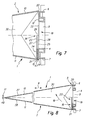
- the two bottom parts 12, 13 are arranged in the finished filter bag 1 below the support plate 4 and form a firmly connected to the support plate 4 bag body bottom 16. In this way it follows that in from the FIGS. 7 and 8 Outstanding position of use, the holding plate 4 transversely to the projecting from the support plate 4 flat walls 10, 11 and the flat walls 10, 11 holds at a distance to each other.
- the flat walls 10, 11 are welded together or fixedly and tightly connected to each other by a glued Faltwickel.
- the two flat walls 10, 11, as shown FIG. 8 it can be seen in the direction of the transverse holding plate 4 pointed away from each other away.
- the two bottom parts 12, 13 are in the position of use in each case along a bending line 20 and 21 at an angle from the facing flat wall 10 and 11 from.
- the filter bag 1 is folded flat by the holding plate 4 together with the bag body bottom 16 around one of the two bending lines, conveniently around the bending line 20 as a pivot center in the direction indicated by arrow 18 to the outgoing from the bending line 20 flat wall 10 turns back.
- the other flat wall 11 is bent accordingly.
- the bag body bottom 16 has one of the passage opening 9 of the holding plate 4 adjacent inlet hole assembly 19, so that the sucked dust air passes through the passage opening 9 and the inlet hole assembly 19 into the bag interior.
- the particles contained in the dust air are retained by the wall of the bag body 2.
- the freed from the dust particles air passes through the wall of the bag body 2 through to the outside.
- the holding plate 4 is arranged on the outside of one of the two bottom parts of the bag body 2, in this case on the attached to the flat wall 10 bottom portion 12 and fixed, in particular by gluing connected thereto, so that not only results in a solid cohesion but at the same time the transition from the passage opening 9 of the holding plate 4 is sealed to the entrance hole assembly 19 of the bag body bottom 16 to the outside.
- the first bottom part 12 extends, starting from its bending line 20, over the passage opening 9 of the holding plate 4 away and contains a first inlet hole 22, which is part of the inlet hole assembly 19 and aligned with the passage opening 9 of the holding plate 4.
- the second bottom part 13 forms an inwardly folded against the holding plate 4 facing away from the inside of the first bottom section 12 and along the support plate 4 extending bottom fold 23 with two fold legs 24, 25, which merge into one another at a fold crest 26.
- a pleat leg 24 extends from the bending line 21, at which the second bottom part 13 to the Flat wall 11 is attached, to the pleat crest 26.
- the other pleat leg 25 extends from the pleat crest 26 to the end 15 of the second bottom portion 13th
- the bottom fold 23 is folded inwards to such an extent that its pleat crest 26 is arranged approximately in the middle of the first entry hole 22 of the first bottom section 12 so that the pleat crest 26 extends approximately along the diameter line of the first entry hole 22 extending in the longitudinal direction 5 of the support plate 4 runs.
- the two pleat legs 24, 25 each contain an outgoing from the pleat crest 26, i. on the pleat leg 26 open-edged inlet half-hole 27, 28.
- the two inlet half-holes 27, 28 thus go on the pleat crest 26, so to speak into each other and overlap.
- the two inlet half-holes 27, 28 are further arranged adjacent to the facing half of the first inlet hole 22, so that the inlet hole assembly 19 on the one hand of the pleat crest 26 of the bending line 20 facing half of the passage opening 9 of the holding plate 4 and the other part of the pleat crest 26 of the bending line 20 remote half of the passage opening 9 and the two aligned with this inlet half-holes 27, 28 of the second bottom part 13 is formed.
- the pleat leg 24 facing the first floor section 12 is firmly and tightly connected to the first floor section 12. Furthermore, the two pleat legs 24, 25 are solid and tight connected with each other.
- the respective bonding is advantageously carried out by gluing, in particular by hot gluing.
- the ends 14, 15 of the two bottom parts 12, 13 are firmly connected to each other.
- the two bottom parts 12, 13 are expediently connected to one another in the vicinity of the respective longitudinal edge 7 of the retaining plate 4.
- the holding plate 4 and the bag body bottom 16 are at right angles to the longitudinal direction 5 about the same width. Further, the arrangement is suitably made so that the passage opening 9 of the support plate 4 in the width direction of the support plate 4 is centrally located on this and the first entrance hole 22 in alignment with the passage opening 9 and that the pleat crest 26 of the bottom fold 23 extends in half the width of the support plate 4.
- the filter bag 1 has on both sides thereof in each case a side fold 30, 31 folded inwards between the two flat walls 10, 11 over its entire length, in the use of the filter bag 1, when it inflates through the air sucked in, is everted, so that the bag volume increases accordingly.
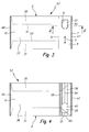
- an initial bag 32 (see Figures 1 and 2 ), which is formed by two equal sized and identically contoured blank material pieces 33, 34 of the filter material, which are superimposed and welded together along its peripheral edge, so that a circumferential weld 35 is formed, which consists of successive weld seam areas composed.
- One of these weld seam regions, the weld seam region 47 connects the two ends 14, 15 of the two bottom parts 12, 13 in the finished filter bag 1.
- Another weld seam region, the weld seam region 48 connects the two at the finished filter bag 1 on the longitudinal side 17 of the holding plate 4 Flat walls 10, 11 with each other.
- Each of the two cut material pieces 33, 34 forms a flat-wall material region 37, 38 which results in the finished filter bag 1, a bottom-end material region 39, 40 resulting from the respective bottom part 12, 13 and a gusset leg on each side.
- a through recess 45 is attached through both bottom part material areas 41, 42, which in the finished filter bag 1 on the one hand the first entrance hole 22 of the first bottom section 12 and on the other hand, the second inlet hole 29 of the second Floor lot 13 results.
- the two inlet holes 22, 29 are thus produced in a single step and are inevitably aligned with each other. From the second entry hole 29 later arise the two already mentioned entry half-holes 27, 28th
- the two side folds 30, 31 are folded inwardly between the two flat-wall material regions 37, 38.
- the one side fold 30 is formed by the two side fold leg material areas 41 and 43 and the other side fold 31 is formed by the two other side fold leg material areas 42, 44.
- the two lateral weld seam areas 49, 50 yield, after the folding in of the lateral folds 30, 31, their side-fold peaks 51, 52.
- the holding plate 4 is attached to the bottom-portion material region 39 of the blank material piece 33, so that the out of the FIGS. 3 and 4 resulting intermediate bag 53 results.
- the bottom plate material region 40 of the other flat-wall material region 38 facing away from the holding plate 4 is folded in, so that the bottom fold 23 is formed.
- This folding process is over FIG. 6 seen.
- the first bottom-part material region 39 which carries the holding plate 4, bends off the flat-wall material region 37 at the bending line 20.
- the bottom fold legs 24, 25 are completely folded and placed against the first bottom section material region 39 or the first bottom section 12.
- the two bottom pleat legs 24, 25 are glued together and the side pleat leg 25 with the first bottom section 12.
- the second bottom part 13 has a bottom fold crest 26 corresponding Sollfaltline 54.
- This desired fold line 54 can be formed by a weld line which has been introduced into the respective cut piece of material 34.
- At least one of the two bottom pleat legs in the expedient embodiment of the base pleat leg 24 facing away from the support plate 4, is solidified in itself, in particular by hot stamping.
- This solidification already takes place in the blank material piece 34, as shown in FIGS Figures 2 and 4 evident.
- This is the solidification zone 55 shown with cross-hatching.
- This material consolidation does not yield only a stable counter surface when gluing the bottom fold legs 24, 25 but also prevents damage to the filter material during hot bonding.
- the layers of material forming the second bottom section 13 may be connected to one another in a punctiform and / or line-like and / or planar manner, so that the material layers can not shift relative to each other when the bottom fold 23 is folded.
- the joining of the material layers by welding or gluing takes place.
- this joining of the material layers on the one hand of the bottom pleat crest 26 takes place through the solidification region 55 - if such a solidification region were missing, for example, would suffice a weld line - and on the other hand the bottom pleat crest 26 through a weld line 56.
- the two pleat legs 24, 25 of the bottom fold 23 each have an entrance half-hole 27, 28 originating from the pleat crest 26, so that the two entry half-holes 27, 28 merge at the pleat crest 26, the two entry pleats 26 Half holes 27, 28 adjacent to the facing half of the first entrance hole 22 are arranged.
- these half-holes 27, 28 can also be omitted so that the pleat crest runs uninterruptedly over the first entry hole 22.
- This embodiment is readily conceivable, so that was dispensed with a separate presentation.
- the area of the bottom fold crossing the entry hole 22 is pushed aside by the incoming air flow or a connection piece arranged on the vacuum cleaner, inserted through the entry hole 22, so that the air practically undisturbed passes into the bag interior.
- the omission of the entry half-holes lowers the manufacturing costs, since the punching of the second bottom portion 13 and the sealing bonding of the pleat legs 24, 25 omitted.
Abstract
Description
Die Erfindung betrifft einen Staubfilterbeutel für Staubsauger, in Gestalt eines Blockbodenbeutels, mit einem zwei einander gegenüberliegende Flachwände bildenden Beutelkörper aus flexiblem Filtermaterial und einer an einem der Längsenden des Filterbeutels angeordneten, eine Durchtrittsöffnung aufweisenden Halteplatte zum Halten des Filterbeutels im Staubsauger, wobei der Beutelkörper zwei jeweils an eine der Flachwände angesetzte und endseitig miteinander verbundene Bodenpartien aufweist, die unterhalb der Halteplatte angeordnet sind und einen fest mit der Halteplatte verbundenen Beutelkörperboden bilden, so dass in der Gebrauchslage die Halteplatte quer zu den Flachwänden steht und die Flachwände im Abstand zueinander gehalten werden, wobei die Halteplatte auf der Außenseite der ersten der beiden Bodenpartien angeordnet ist und die zweite Bodenpartie eine nach innen eingefaltete, gegen die Innenseite der ersten Bodenpartie gelegte und sich längs der Halteplatte erstreckende Bodenfalte bildet und wobei der Beutelkörperboden eine der Durchtrittsöffnung der Halteplatte benachbarte Eintritts-Lochanordnung aufweist.The invention relates to a dust filter bag for vacuum cleaners, in the form of a block bottom bag, with a two opposing flat walls forming bag body made of flexible filter material and arranged at one of the longitudinal ends of the filter bag, a passage opening holding plate for holding the filter bag in the vacuum cleaner, the bag body two each attached to one of the flat walls and end mutually connected bottom parts, which are arranged below the holding plate and form a fixed to the holding plate connected bag body bottom, so that in the position of use, the holding plate is transverse to the flat walls and the flat walls are kept at a distance from each other, wherein the holding plate is arranged on the outside of the first of the two bottom parts and the second bottom part has an inwardly folded, laid against the inside of the first bottom part and extending along the holding plate Forming bottom fold and wherein the bag body bottom has a passage opening of the holding plate adjacent entrance hole assembly.
Blockbodenbeutel, auch Klotzbodenbeutel genannt, werden sowohl bei Haushaltsstaubsaugern als auch bei gewerblich eingesetzten Staubsaugern verwendet. Dabei wird mittels eines Staubsaugergebläses ein Saugstrom erzeugt, der die mit dem Staub oder dergleichen Partikel beladene Luft in einen Saugschlauch und von dort durch die Durchtrittsöffnung der Halteplatte und die Eintritts-Lochanordnung des Beutelkörperbodens in das Beutelinnere fördert. Die in der angesaugten Luft enthaltenen Partikel werden von der aus Filtermaterial bestehenden Wandung des Beutelkörpers zurückgehalten. Die vom Staub befreite Luft durchdringt die Beutelwandung und wird in die Umgebung ausgeblasen.Block bottom bags, also called block bottom bags, are used both in household vacuum cleaners and in commercially used vacuum cleaners. In this case, a suction flow is generated by means of a vacuum cleaner fan, which loads the loaded with the dust or the like particles of air into a suction hose and from there through the passage opening of the holding plate and the inlet hole arrangement of the bag body bottom promotes into the bag interior. The particles contained in the intake air are retained by the filter material wall of the bag body. The dust-free air penetrates the bag wall and is blown into the environment.
Blockbodenbeutel sind üblicherweise an einem ihrer Längsenden beispielsweise durch Anbringen einer Schweißnaht oder eines durch mehrmaliges Umschlagen und Kleben hergestellten Faltwickels verschlossen und weisen am entgegengesetzten Längsende eine die Verbindung zum Staubsauger herstellende Halteplatte auf.Block bottom bags are usually closed at one of their longitudinal ends, for example, by attaching a weld seam or a folding wrap produced by repeated folding and gluing and at the opposite longitudinal end have a holding plate which connects to the vacuum cleaner.
Bei einem aus der
Der vorliegenden Erfindung liegt die Aufgabe zugrunde, einen Staubfilterbeutel der eingangs genannten Art zu schaffen, der nicht nur einen verhältnismäßig einfachen Aufbau aufweist sondern für dessen Herstellung möglichst wenig Filtermaterial erforderlich ist.The present invention has for its object to provide a dust filter bag of the type mentioned, which not only has a relatively simple structure but as little as possible filter material is required for its production.
Diese Aufgabe wird erfindungsgemäß dadurch gelöst, dass die erste Bodenpartie ein erstes Eintrittsloch enthält und dass die Bodenfalte der zweiten Bodenpartie so weit nach innen eingefaltet ist, dass ihr Faltenscheitel etwa in der Mitte des ersten Eintrittsloches angeordnet ist.This object is achieved in that the first bottom section includes a first entrance hole and that the bottom fold of the second bottom section is folded so far inward that its pleat crest is arranged approximately in the middle of the first inlet hole.
Auf diese Weise sind die beiden jeweils an eine der Flachwände angesetzten Bodenpartien im Wesentlichen gleich groß. Sind die Halteplatte und die erste Bodenpartie beispielsweise gleich breit und ist die Durchtrittsöffnung der Halteplatte in Breitenrichtung mittig angeordnet, wird für die zweite Bodenpartie ebenfalls nur ein in der Breite der Halteplatte entsprechender Materialbereich benötigt, so dass man mit einem minimalen Materialaufwand auskommt.In this way, the two each attached to one of the flat walls bottom parts are substantially the same size. If the holding plate and the first bottom part, for example, the same width and the passage opening of the holding plate in the width direction centered, also only one in the width of the holding plate corresponding material area is required for the second bottom part, so that you can make do with a minimal cost of materials.
Der Faltenscheitel kann ununterbrochen über das erste Eintrittsloch hinweg verlaufen. Es kann jedoch auch vorgesehen sein, dass die beiden am Faltenscheitel ineinander übergehenden Faltenschenkel der zweiten Bodenpartie jeweils ein vom Faltenscheitel ausgehendes Eintritts-Halbloch enthalten, so dass die beiden Eintritts-Halblöcher am Faltenscheitel ineinander übergehen, wobei die beiden Eintritts-Halblöcher benachbart zur zugewandten Hälfte des ersten Eintrittsloches angeordnet sind. In beiden Fällen kann der Luftstrom in das Beutelinnere eintreten, da die eine Hälfte des Eintrittsloches der ersten Bodenpartie unmittelbar in das Beutelinnere mündet und im erstgenannten Falle die Bodenfalte entweder durch den Luftstrom oder einen am Staubsauger angeordneten Anschlussstutzen weggedrückt wird, während im zweitgenannten Falle die andere Hälfte des Eintrittsloches fluchtend zu den dem Beutelinneren zugewandten, sich überdeckenden Eintritts-Halblöchern der zweiten Bodenpartie angeordnet ist.The pleat crest can run continuously over the first entry hole. However, it may also be provided that the two pleat limbs of the second bottom part, which merge into each other at the pleat crest, each contain an entry half hole emanating from the pleat crest, so that the two entry halfholes merge into one another at the pleat crest, with the two inlet halfholes adjacent to the facing half of the first entrance hole are arranged. In both cases, the air flow can enter the bag interior, since one half of the inlet hole of the first bottom part opens directly into the bag interior and in the former case, the bottom fold is pushed away either by the air flow or arranged on a vacuum cleaner connection, while in the latter case the other Half of the inlet hole is arranged in alignment with the inside of the bag facing, overlapping inlet half-holes of the second bottom section.
Zweckmäßige Ausgestaltungen der Erfindung sind in den Unteransprüchen angegeben.Advantageous embodiments of the invention are specified in the subclaims.
Nachstehend wird ein Ausführungsbeispiel der Erfindung anhand der Zeichnung im Einzelnen erläutert. Es zeigen:
Figur 1- einen Ausgangsbeutel für die Fertigung eines erfin- dungsgemäßen Staubfilterbeutels in dem Pfeil I, III in
Figur 5 Figur 2- den Ausgangsbeutel nach
Figur 1Figur 5 Figur 3- einen aus dem Ausgangsbeutel gemäß den
Figuren 1 und 2Figur 1Figur 5 Figur 4- den Zwischenbeutel nach
Figur 3Figur 2Figur 5 Figur 5- den Zwischenbeutel nach den
Figuren 3 und 4Figur 3 Figur 6- die Anordnung nach
Figur 5 Figur 7- die Anordnung nach den
Figuren 5 und 6 Figur 8- den erfindungsgemäßen Staubfilterbeutel im den Fi-
guren 5 bis 7 entsprechenden Schnitt in verkleiner- ter Gesamtansicht (Figur 7Figur 8 ), wobei sich der Beutel in seiner Gebrauchslage befindet.
- FIG. 1
- an initial bag for the manufacture of a dust filter bag according to the invention in the arrow I, III in FIG
FIG. 5 corresponding plan view, - FIG. 2
- after the initial bag
FIG. 1 in the opposite plan view according to arrow II, VI inFIG. 5 . - FIG. 3
- one from the starting bag according to the
Figures 1 and 2 by folding in gussets and attaching the retaining plate resulting intermediate bag in theFIG. 1 corresponding plan view according to arrow I, III inFIG. 5 , wherein the retaining plate is only schematically drawn, - FIG. 4
- the intermediate bag after
FIG. 3 in the opposite, theFIG. 2 corresponding plan view according to arrow II, IV inFIG. 5 . - FIG. 5
- the intermediate bag after the
FIGS. 3 and 4 in section along the section line VV inFIG. 3 in an enlarged partial view, - FIG. 6
- the arrangement after
FIG. 5 during folding of the bottom fold, - FIG. 7
- the arrangement after the
FIGS. 5 and 6 after completion of the dust filter bag according to the invention and - FIG. 8
- the dust filter bag according to the invention in section corresponding to FIGS. 5 to 7 in a reduced overall view (
FIG. 7 shows a section outFIG. 8 ), wherein the bag is in its position of use.
Der aus den
Der Beutelkörper 2 besteht aus flexiblem Filtermaterial, das ein- oder mehrlagig sein kann. Die Art des Filtermaterials ist vorliegend von untergeordneter Bedeutung. Es kommen die üblichen Materialien infrage, insbesondere zumindest im Wesentlichen aus Kunststoff bestehende Faserstrukturen. Vorliegend handelt es sich um ein schweißbares Vliesmaterial.The
Die Halteplatte 4 ist steif ausgebildet und besteht aus Kunststoff. Sie dient zum Festlegen des Filterbeutels 1 in einem Staubsauger, der eine entsprechende Aufnahme für die Halteplatte aufweist. Die Halteplatte 4 hat im Wesentlichen die Gestalt eines länglichen Rechtecks. Die Längsrichtung der Halteplatte 4 und somit deren Längsränder 6, 7 verlaufen quer zur Längsrichtung 8 des Filterbeutels 1. Die Halteplatte 4 ist in
Der Beutelkörper 2 bildet zwei einander gegenüberliegende Flachwände 10, 11, die bei dem vorliegenden Ausführungsbeispiel eine rechteckige Gestalt aufweisen. An jede der beiden Flachwände 10, 11 ist am dem Längsende 3 zugewandten Wandende eine Beutelkörper-Bodenpartie 12 bzw. 13 einstückig angesetzt, deren Enden 14, 15 miteinander verbunden sind. Dies kann beispielsweise durch Kleben oder mittels eines geklebten Faltwickels oder insbesondere durch Schweißen erfolgen. Es ist jedoch auch möglich, die beiden Bodenpartien 12, 13 einstückig ineinander übergehen zu lassen, so dass die beiden Flachwände 10, 11 zusammen mit den beiden Bodenpartien 12, 13 von einem einstückigen Filtermaterial gebildet werden können.The
Die beiden Bodenpartien 12, 13 sind beim fertigen Filterbeutel 1 unterhalb der Halteplatte 4 angeordnet und bilden einen fest mit der Halteplatte 4 verbundenen Beutelkörperboden 16. Auf diese Weise ergibt sich, dass in der aus den
Am dem Längsende 3 entgegengesetzten Längsende 17 ist der Beutelkörper 2 geschlossen, beispielsweise indem die Flachwände 10, 11 miteinander verschweißt oder durch einen geklebten Faltwickel fest und dicht miteinander verbunden sind. In der Gebrauchslage verlaufen die beiden Flachwände 10, 11, wie aus
Für Verpackungszwecke wird der Filterbeutel 1 flach zusammengelegt, indem man die Halteplatte 4 zusammen mit dem Beutelkörperboden 16 um eine der beiden Biegelinien, zweckmäßigerweise um die Biegelinie 20 als Schwenkzentrum in Richtung gemäß Pfeil 18 zur von der Biegelinie 20 abgehenden Flachwand 10 hin einschwenkt. Die andere Flachwand 11 wird dabei entsprechend abgeknickt.For packaging purposes, the
Der Beutelkörperboden 16 weist eine der Durchtrittsöffnung 9 der Halteplatte 4 benachbarte Eintritts-Lochanordnung 19 auf, so dass die angesaugte Staubluft durch die Durchtrittsöffnung 9 und die Eintritts-Lochanordnung 19 in das Beutelinnere gelangt. Die in der Staubluft enthaltenen Partikel werden von der Wandung des Beutelköpers 2 zurückgehalten. Die von den Staubpartikeln befreite Luft gelangt durch die Wandung des Beutelkörpers 2 hindurch nach außen.The bag body bottom 16 has one of the
Die Halteplatte 4 ist auf der Außenseite einer der beiden Bodenpartien des Beutelkörpers 2, vorliegend auf der an die Flachwand 10 angesetzten Bodenpartie 12 angeordnet und fest, insbesondere durch Kleben mit dieser verbunden, so dass sich nicht nur ein fester Zusammenhalt ergibt sondern gleichzeitig der Übergang von der Durchtrittsöffnung 9 der Halteplatte 4 zur Eintritts-Lochanordnung 19 des Beutelkörperbodens 16 nach außen hin abgedichtet wird.The holding
Die erste Bodenpartie 12 erstreckt sich, ausgehend von ihrer Biegelinie 20, über die Durchtrittsöffnung 9 der Halteplatte 4 hinweg und enthält ein erstes Eintrittsloch 22, das Bestandteil der Eintritts-Lochanordnung 19 und fluchtend zur Durchtrittsöffnung 9 der Halteplatte 4 angeordnet ist.The first
Die zweite Bodenpartie 13 bildet eine nach innen eingefaltete, gegen die der Halteplatte 4 abgewandte Innenseite der ersten Bodenpartie 12 gelegte und sich längs der Halteplatte 4 erstreckende Bodenfalte 23 mit zwei Faltenschenkeln 24, 25, die an einem Faltenscheitel 26 ineinander übergehen. Im Schnitt gesehen erstreckt sich der eine Faltenschenkel 24 von der Biegelinie 21, an der die zweite Bodenpartie 13 an die Flachwand 11 angesetzt ist, bis zum Faltenscheitel 26. Der andere Faltenschenkel 25 erstreckt sich von dem Faltenscheitel 26 bis zum Ende 15 der zweiten Bodenpartie 13.The second
Die Bodenfalte 23 ist so weit nach innen eingefaltet, dass ihr Faltenscheitel 26 etwa in der Mitte des ersten Eintrittsloches 22 der ersten Bodenpartie 12 angeordnet ist, so dass der Faltenscheitel 26 etwa entlang der sich in Längsrichtung 5 der Halteplatte 4 erstreckenden Durchmesserlinie des ersten Eintrittsloches 22 verläuft. Die beiden Faltenschenkel 24, 25 enthalten jeweils ein vom Faltenscheitel 26 ausgehendes, d.h. am Faltenschenkel 26 randoffenes Eintritts-Halbloch 27, 28. Die beiden Eintritts-Halblöcher 27, 28 gehen somit am Faltenscheitel 26 sozusagen ineinander über und überdecken sich. Die beiden Eintritts-Halblöcher 27, 28 sind ferner benachbart zur zugewandten Hälfte des ersten Eintrittsloches 22 angeordnet, so dass die Eintritts-Lochanordnung 19 einerseits des Faltenscheitels 26 von der der Biegelinie 20 zugewandten Hälfte der Durchtrittsöffnung 9 der Halteplatte 4 und andererseits des Faltenscheitels 26 von der der Biegelinie 20 abgewandten Hälfte der Durchtrittsöffnung 9 und den beiden mit dieser fluchtenden Eintritts-Halblöchern 27, 28 der zweiten Bodenpartie 13 gebildet wird.The
Im gestreckten Zustand der zweiten Bodenpartie 13, d.h. vor dem Einfalten der Bodenfalte 23, ergeben die beiden Eintritts-Halblöcher 27, 28 ein zusammenhängendes zweites Eintrittsloch 29, das dem an der ersten Bodenpartie 12 angeordneten ersten Eintrittsloch 22 entspricht.In the stretched state of the second
Der der ersten Bodenpartie 12 zugewandte Faltenschenkel 24 ist fest und dicht mit der ersten Bodenpartie 12 verbunden. Ferner sind die beiden Faltenschenkel 24, 25 fest und dicht miteinander verbunden. Das jeweilige Verbinden erfolgt zweckmäßigerweise durch Kleben, insbesondere durch Heißkleben.The
Wie bereits erwähnt, sind die Enden 14, 15 der beiden Bodenpartien 12, 13 fest miteinander verbunden. Dabei sind die beiden Bodenpartien 12, 13 zweckmäßigerweise in der Nachbarschaft des betreffenden Längsrandes 7 der Halteplatte 4 miteinander verbunden.As already mentioned, the ends 14, 15 of the two
Die Halteplatte 4 und der Beutelkörperboden 16 sind rechtwinkelig zur Längsrichtung 5 etwa gleich breit. Ferner ist die Anordnung zweckmäßigerweise so getroffen, dass die Durchtrittsöffnung 9 der Halteplatte 4 in Breitenrichtung der Halteplatte 4 mittig an dieser und das erste Eintrittsloch 22 fluchtend zur Durchtrittsöffnung 9 angeordnet ist und dass der Faltenscheitel 26 der Bodenfalte 23 in halber Breite der Halteplatte 4 verläuft.The holding
Bevor auf weitere Einzelheiten und die Fertigung des Filterbeutels 1 eingegangen wird, wird noch darauf hingewiesen, dass der Filterbeutel 1 an seinen beiden Seiten jeweils eine zwischen die beiden Flachwände 10, 11 nach innen eingefaltete, über ihre gesamte Länge ausstülpbare Seitenfalte 30, 31 aufweist, die beim Gebrauch des Filterbeutels 1, wenn sich dieser durch die eingesaugte Luft aufbläht, ausgestülpt wird, so dass sich das Beutelvolumen entsprechend vergrößert.Before discussing further details and the manufacture of the
Bei der Fertigung des Filterbeutels 1 wird zunächst ein Ausgangsbeutel 32 (siehe
Jeder der beiden Zuschnitts-Materialstücke 33, 34 bildet einen beim fertigen Filterbeutel 1 die jeweilige Flachwand 10, 11 ergebenden Flachwand-Materialbereich 37, 38, einen die jeweilige Bodenpartie 12, 13 ergebenden Bodenpartie-Materialbereich 39, 40 und an jeder Seite einen Seitenfaltenschenkel-Materialbereich 41, 42, bzw. 43, 44.Each of the two
Nach dem Verbinden der beiden Zuschnitts-Materialstücke 33, 34 miteinander wird durch beide Bodenpartie-Materialbereiche 41, 42 hindurch eine durchgehende Ausnehmung 45 angebracht, die bei fertigem Filterbeutel 1 einerseits das erste Eintrittsloch 22 der ersten Bodenpartie 12 und andererseits das zweite Eintrittsloch 29 der zweiten Bodenpartie 13 ergibt. Die beiden Eintrittslöcher 22, 29 werden also in einem einzigen Schritt hergestellt und fluchten zwangsläufig miteinander. Aus dem zweiten Eintrittsloch 29 entstehen später die beiden bereits erwähnten Eintritts-Halblöcher 27, 28.After joining the two
Anschließend werden die beiden Seitenfalten 30, 31 nach innen zwischen die beiden Flachwand-Materialbereiche 37, 38 eingefaltet. Dabei wird die eine Seitenfalte 30 von den beiden Seitenfaltenschenkel-Materialbereichen 41 und 43 und die andere Seitenfalte 31 von den beiden anderen Seitenfaltenschenkel-Materialbereichen 42, 44 gebildet. Die beiden seitlichen Schweißnahtbereiche 49, 50 ergeben nach dem Einfalten der Seitenfalten 30, 31 deren Seitenfaltenscheitel 51, 52.Subsequently, the two side folds 30, 31 are folded inwardly between the two flat-
Nach dem Einfalten der Seitenfalten 30, 31 wird auf dem Bodenpartie-Materialbereich 39 des Zuschnitts-Materialstücks 33 die Halteplatte 4 befestigt, so dass sich der aus den
Sodann wird der der Halteplatte 4 abgewandte Bodenpartie-Materialbereich 40 des anderen Flachwand-Materialbereichs 38 eingefaltet, so dass die Bodenfalte 23 gebildet wird. Dieser Einfaltvorgang ist aus
Die zweite Bodenpartie 13 weist eine dem Bodenfaltenscheitel 26 entsprechende Sollfaltlinie 54 auf. Diese Sollfaltlinie 54 kann von einer Schweißlinie gebildet werden, die in das betreffende Zuschnitts-Materialstück 34 eingebracht worden ist.The second
Ferner ist zweckmäßigerweise vorgesehen, dass mindestens einer der beiden Bodenfaltenschenkel, beim zweckmäßigen Ausführungsbeispiel der der Halteplatte 4 abgewandte Bodenfaltenschenkel 24, insbesondere durch Heißprägen in sich verfestigt ist. Dieses Verfestigen erfolgt bereits im Zuschnitt-Materialstück 34, wie aus den
Schließlich können im Falle von mehrlagigem Filtermaterial die die zweite Bodenpartie 13 bildenden Materiallagen punktartig und/oder linienartig und/oder flächig verschiebefest miteinander verbunden sein, so dass sich die Materiallagen beim Falten der Bodenfalte 23 nicht gegeneinander verschieben können. Zweckmäßigerweise erfolgt das Verbinden der Materiallagen durch Schweißen oder Kleben. Beim Ausführungsbeispiel erfolgt dieses Verbinden der Materiallagen einerseits des Bodenfaltenscheitels 26 durch den Verfestigungsbereich 55 - fehlt ein solcher Verfestigungsbereich, würde beispielsweise eine Schweißlinie genügen - und andererseits des Bodenfaltenscheitels 26 durch eine Schweißlinie 56.Finally, in the case of multilayer filter material, the layers of material forming the
Bei dem dargestellten und beschriebenen Ausführungsbeispiel enthalten die beiden Faltenschenkel 24, 25 der Bodenfalte 23 jeweils ein vom Faltenscheitel 26 ausgehendes Eintritts-Halbloch 27, 28, so dass die beiden Eintritts-Halblöcher 27, 28 am Faltenscheitel 26 ineinander übergehen, wobei die beiden Eintritts-Halblöcher 27, 28 benachbart zur zugewandten Hälfte des ersten Eintrittsloches 22 angeordnet sind.In the illustrated and described embodiment, the two
Prinzipiell können diese Halblöcher 27, 28 jedoch auch weggelassen werden, so dass der Faltenscheitel ununterbrochen über das erste Eintrittsloch 22 hinweg verläuft. Diese Ausführungsform ist ohne weiteres vorstellbar, so dass auf eine gesonderte Darstellung verzichtet wurde. In diesem Falle wird beim Betrieb der das Eintrittsloch 22 überquerende Bereich der Bodenfalte durch den ankommenden Luftstrom oder einen am Staubsauger angeordneten, durch das Eintrittsloch 22 gesteckten Anschlussstutzen zur Seite gedrückt, so dass die Luft praktisch ungestört in das Beutelinnere gelangt. Das Weglassen der Eintritts-Halblöcher erniedrigt die Fertigungskosten, da das Lochen der zweiten Bodenpartie 13 und das abdichtende Verkleben der Faltenschenkel 24, 25 entfallen.In principle, however, these half-
Claims (13)
Applications Claiming Priority (1)
| Application Number | Priority Date | Filing Date | Title |
|---|---|---|---|
| DE200720017064 DE202007017064U1 (en) | 2007-12-07 | 2007-12-07 | Dust filter bag for vacuum cleaners |
Publications (3)
| Publication Number | Publication Date |
|---|---|
| EP2067427A2 true EP2067427A2 (en) | 2009-06-10 |
| EP2067427A3 EP2067427A3 (en) | 2010-05-26 |
| EP2067427B1 EP2067427B1 (en) | 2011-06-22 |
Family
ID=39198840
Family Applications (1)
| Application Number | Title | Priority Date | Filing Date |
|---|---|---|---|
| EP20080018357 Active EP2067427B1 (en) | 2007-12-07 | 2008-10-21 | Dust filter bag for a vacuum cleaner |
Country Status (2)
| Country | Link |
|---|---|
| EP (1) | EP2067427B1 (en) |
| DE (2) | DE202007017064U1 (en) |
Cited By (3)
| Publication number | Priority date | Publication date | Assignee | Title |
|---|---|---|---|---|
| US10080474B2 (en) | 2013-03-15 | 2018-09-25 | Eurofilters Holding N.V. | Vacuum cleaner filter bag |
| US10178932B2 (en) | 2010-03-19 | 2019-01-15 | Eurofilters Holding N.V. | Vacuum cleaner filter bag |
| CN110270167A (en) * | 2019-07-31 | 2019-09-24 | 常州春南环保设备有限公司 | A kind of dust settling pocket |
Families Citing this family (3)
| Publication number | Priority date | Publication date | Assignee | Title |
|---|---|---|---|---|
| DE202009004433U1 (en) | 2009-03-26 | 2009-06-04 | Branofilter Gmbh | Block bottom bag with additional weld and Sollfaltlinien |
| ATE556635T1 (en) | 2010-02-19 | 2012-05-15 | Eurofilters Holding Nv | VACUUM CLEANER FILTER BAGS WITH SIDE FOLD |
| DE102012019470B4 (en) * | 2012-10-03 | 2016-02-18 | Elku Bauteile GmbH | Dust bag with a suction opening with a collar and a closure device |
Citations (1)
| Publication number | Priority date | Publication date | Assignee | Title |
|---|---|---|---|---|
| EP1192890B1 (en) | 2000-09-29 | 2006-05-03 | VORWERK & CO. INTERHOLDING GmbH | Dust bag for a vacuum cleaner |
Family Cites Families (2)
| Publication number | Priority date | Publication date | Assignee | Title |
|---|---|---|---|---|
| JP2857709B2 (en) * | 1989-05-16 | 1999-02-17 | 株式会社日立製作所 | Dust collection filter for vacuum cleaner |
| JP2002078653A (en) * | 2000-06-21 | 2002-03-19 | Oshitani Sangyo Kk | Paper bag for vacuum cleaner |
-
2007
- 2007-12-07 DE DE200720017064 patent/DE202007017064U1/en not_active Expired - Lifetime
-
2008
- 2008-04-01 DE DE102008016596A patent/DE102008016596B4/en not_active Expired - Fee Related
- 2008-10-21 EP EP20080018357 patent/EP2067427B1/en active Active
Patent Citations (1)
| Publication number | Priority date | Publication date | Assignee | Title |
|---|---|---|---|---|
| EP1192890B1 (en) | 2000-09-29 | 2006-05-03 | VORWERK & CO. INTERHOLDING GmbH | Dust bag for a vacuum cleaner |
Cited By (6)
| Publication number | Priority date | Publication date | Assignee | Title |
|---|---|---|---|---|
| US10178932B2 (en) | 2010-03-19 | 2019-01-15 | Eurofilters Holding N.V. | Vacuum cleaner filter bag |
| US10182691B2 (en) | 2010-03-19 | 2019-01-22 | Eurofilters Holding N.V. | Vacuum cleaner filter bag |
| US10188248B2 (en) | 2010-03-19 | 2019-01-29 | Eurofilters Holding N.V. | Vacuum cleaner filter bag |
| EP2366320B2 (en) † | 2010-03-19 | 2022-08-17 | Eurofilters Holding N.V. | Vacuum cleaner filter bag |
| US10080474B2 (en) | 2013-03-15 | 2018-09-25 | Eurofilters Holding N.V. | Vacuum cleaner filter bag |
| CN110270167A (en) * | 2019-07-31 | 2019-09-24 | 常州春南环保设备有限公司 | A kind of dust settling pocket |
Also Published As
| Publication number | Publication date |
|---|---|
| EP2067427A3 (en) | 2010-05-26 |
| DE202007017064U1 (en) | 2008-03-20 |
| DE102008016596B4 (en) | 2010-09-30 |
| EP2067427B1 (en) | 2011-06-22 |
| DE102008016596A1 (en) | 2009-06-10 |
Similar Documents
| Publication | Publication Date | Title |
|---|---|---|
| EP1776909B1 (en) | Vacuum cleaner dust bag | |
| EP1677660B1 (en) | Filter bag and method for the production thereof | |
| EP1683460B1 (en) | Dust filter bag | |
| EP2067427B1 (en) | Dust filter bag for a vacuum cleaner | |
| EP2018111B1 (en) | Dust filter bag | |
| DE102008006769A1 (en) | Dust filter bag producing method, involves raising edge sections of upper web by edge zones of fold limbs resting upon on lower web before and during longitudinal welding, where upper web and lower web are made of weldable material | |
| EP1928288B1 (en) | Filter bag for a vacuum cleaner and method for producing the same | |
| DE102008045683B4 (en) | Dust filter bag device for a vacuum cleaner | |
| EP0444291B1 (en) | Carrier bag for clothing made from thermoplastic plastic and method for its manufacture | |
| EP1683461A1 (en) | Dust filter bag | |
| DE202009004433U1 (en) | Block bottom bag with additional weld and Sollfaltlinien | |
| EP2359730B1 (en) | Vacuum cleaner filter bag with side fold | |
| EP2489292A1 (en) | Bag for a vacuum cleaner | |
| DE10064608A1 (en) | Filter bag for a vacuum cleaner | |
| EP1212971B1 (en) | Dust bag for vacuum cleaner | |
| EP2465397B1 (en) | Vacuum cleaner bag and method for manufacturing same | |
| EP1192890B1 (en) | Dust bag for a vacuum cleaner | |
| DE102010041832B4 (en) | Vacuum cleaner and method for emptying a dust collector from a vacuum cleaner | |
| DE102007005612B4 (en) | Filter bag for a vacuum cleaner | |
| DE202006001587U1 (en) | Filter bag for vacuum cleaner, has folding sections with legs that are folded inwards for forming side walls and connected with one another by longitudinal welded joint that is provided inner side of bag | |
| EP3219236B1 (en) | Holding plate with improved closure | |
| DE202010000933U1 (en) | filter bag | |
| DE102015101316A1 (en) | Method and device for producing a vacuum cleaner bag and vacuum cleaner bag |
Legal Events
| Date | Code | Title | Description |
|---|---|---|---|
| PUAI | Public reference made under article 153(3) epc to a published international application that has entered the european phase |
Free format text: ORIGINAL CODE: 0009012 |
|
| AK | Designated contracting states |
Kind code of ref document: A2 Designated state(s): AT BE BG CH CY CZ DE DK EE ES FI FR GB GR HR HU IE IS IT LI LT LU LV MC MT NL NO PL PT RO SE SI SK TR |
|
| AX | Request for extension of the european patent |
Extension state: AL BA MK RS |
|
| PUAL | Search report despatched |
Free format text: ORIGINAL CODE: 0009013 |
|
| AK | Designated contracting states |
Kind code of ref document: A3 Designated state(s): AT BE BG CH CY CZ DE DK EE ES FI FR GB GR HR HU IE IS IT LI LT LU LV MC MT NL NO PL PT RO SE SI SK TR |
|
| AX | Request for extension of the european patent |
Extension state: AL BA MK RS |
|
| 17P | Request for examination filed |
Effective date: 20100508 |
|
| AKX | Designation fees paid |
Designated state(s): DE IT |
|
| RIC1 | Information provided on ipc code assigned before grant |
Ipc: A47L 9/14 20060101AFI20101229BHEP |
|
| GRAP | Despatch of communication of intention to grant a patent |
Free format text: ORIGINAL CODE: EPIDOSNIGR1 |
|
| GRAS | Grant fee paid |
Free format text: ORIGINAL CODE: EPIDOSNIGR3 |
|
| GRAA | (expected) grant |
Free format text: ORIGINAL CODE: 0009210 |
|
| AK | Designated contracting states |
Kind code of ref document: B1 Designated state(s): DE IT |
|
| REG | Reference to a national code |
Ref country code: DE Ref legal event code: R096 Ref document number: 502008003928 Country of ref document: DE Effective date: 20110804 |
|
| PLBE | No opposition filed within time limit |
Free format text: ORIGINAL CODE: 0009261 |
|
| STAA | Information on the status of an ep patent application or granted ep patent |
Free format text: STATUS: NO OPPOSITION FILED WITHIN TIME LIMIT |
|
| 26N | No opposition filed |
Effective date: 20120323 |
|
| REG | Reference to a national code |
Ref country code: DE Ref legal event code: R097 Ref document number: 502008003928 Country of ref document: DE Effective date: 20120323 |
|
| PGFP | Annual fee paid to national office [announced via postgrant information from national office to epo] |
Ref country code: IT Payment date: 20231031 Year of fee payment: 16 Ref country code: DE Payment date: 20230920 Year of fee payment: 16 |