EP2066395B1 - Électrode résistant à l'humidité avec protection des bords - Google Patents
Électrode résistant à l'humidité avec protection des bords Download PDFInfo
- Publication number
- EP2066395B1 EP2066395B1 EP07841554.4A EP07841554A EP2066395B1 EP 2066395 B1 EP2066395 B1 EP 2066395B1 EP 07841554 A EP07841554 A EP 07841554A EP 2066395 B1 EP2066395 B1 EP 2066395B1
- Authority
- EP
- European Patent Office
- Prior art keywords
- conductive
- adhesive
- conductive flexible
- flexible member
- electrode
- Prior art date
- Legal status (The legal status is an assumption and is not a legal conclusion. Google has not performed a legal analysis and makes no representation as to the accuracy of the status listed.)
- Not-in-force
Links
Images

Classifications
-
- A—HUMAN NECESSITIES
- A61—MEDICAL OR VETERINARY SCIENCE; HYGIENE
- A61N—ELECTROTHERAPY; MAGNETOTHERAPY; RADIATION THERAPY; ULTRASOUND THERAPY
- A61N1/00—Electrotherapy; Circuits therefor
- A61N1/02—Details
- A61N1/04—Electrodes
- A61N1/0404—Electrodes for external use
- A61N1/0408—Use-related aspects
- A61N1/0456—Specially adapted for transcutaneous electrical nerve stimulation [TENS]
-
- A—HUMAN NECESSITIES
- A61—MEDICAL OR VETERINARY SCIENCE; HYGIENE
- A61N—ELECTROTHERAPY; MAGNETOTHERAPY; RADIATION THERAPY; ULTRASOUND THERAPY
- A61N1/00—Electrotherapy; Circuits therefor
- A61N1/02—Details
- A61N1/04—Electrodes
- A61N1/0404—Electrodes for external use
- A61N1/0408—Use-related aspects
- A61N1/0452—Specially adapted for transcutaneous muscle stimulation [TMS]
-
- A—HUMAN NECESSITIES
- A61—MEDICAL OR VETERINARY SCIENCE; HYGIENE
- A61N—ELECTROTHERAPY; MAGNETOTHERAPY; RADIATION THERAPY; ULTRASOUND THERAPY
- A61N1/00—Electrotherapy; Circuits therefor
- A61N1/02—Details
- A61N1/04—Electrodes
- A61N1/0404—Electrodes for external use
- A61N1/0472—Structure-related aspects
- A61N1/0492—Patch electrodes
-
- A—HUMAN NECESSITIES
- A61—MEDICAL OR VETERINARY SCIENCE; HYGIENE
- A61N—ELECTROTHERAPY; MAGNETOTHERAPY; RADIATION THERAPY; ULTRASOUND THERAPY
- A61N1/00—Electrotherapy; Circuits therefor
- A61N1/02—Details
- A61N1/04—Electrodes
- A61N1/0404—Electrodes for external use
- A61N1/0472—Structure-related aspects
- A61N1/0476—Array electrodes (including any electrode arrangement with more than one electrode for at least one of the polarities)
-
- A—HUMAN NECESSITIES
- A61—MEDICAL OR VETERINARY SCIENCE; HYGIENE
- A61N—ELECTROTHERAPY; MAGNETOTHERAPY; RADIATION THERAPY; ULTRASOUND THERAPY
- A61N1/00—Electrotherapy; Circuits therefor
- A61N1/02—Details
- A61N1/04—Electrodes
- A61N1/0404—Electrodes for external use
- A61N1/0472—Structure-related aspects
- A61N1/048—Electrodes characterised by a specific connection between lead and electrode
Definitions
- the present disclosure generally relates to electrodes and, more particularly, electrodes suitable for transcutaneous nerve and/or muscle stimulation and biological signal recording.
- the invention is set out in the appended claims.
- Medical electrodes must provide an even electrical distribution to a patient's skin over an entire surface of the electrode to assure proper coupling. Because of the curvaceous nature of the human body, it is apparent that medical electrodes for use thereon must be flexible not only for conformation with a patient's skin contours, but also to accommodate relative movement of the patient's skin.
- Electrodes In order to provide uniform electrical coupling, heretofore developed electrodes have utilized conductive fabrics and foils in combination with a conductive and flexible adhesive in order to uniformly couple electrical signals to and/or from an electrical lead wire, or connector.
- a number of electrodes have provided impedance compensation for directing electrical pulses from the lead wire uniformly throughout an electrode, such as, for example, U.S. Patent No. 5,038,796 entitled, ELECTRICAL STIMULATION ELECTRODE WITH IMPEDANCE COMPENSATION, and U.S. Patent No. 5,904,712 CURRENT CONTROLLING ELECTRODE to Axelgaard.
- U.S. Patent No. 4,736,752 teaches the control of current density across an electrode through the use of conductive ink design areas.
- US 5,785,040 discloses a medical electrode according to the preamble of claim 1.
- Electrodes have compromised the flexibility of the electrode in order to provide adequate current densities over the entire contact area of the electrode.
- Such electrodes typically have utilized a metallic mesh, or foil, to provide conductivity and utilize a conductive gel between the electrode and the patient's skin in order to accommodate the movement therebetween.
- Such use of foil or mesh often cause burning or hot spots at electrode edges.
- a common prior art problem with medical electrodes using a conductive adhesive is the leakage of electrical current from edges of the conductive adhesive, or gel, which is known in the art as edge biting.
- exposed adhesive, or gel has a tendency to dry upon exposure to air and, in addition, entry of foreign material to the gel is possible because of the adhesive nature thereof.
- a further problem with most prior art electrodes is the fact that the conductive hydrogels utilized to contact the electrode with a patient's skin are hydrophilic and therefore lose their adhesiveness when satiated with water. Thus, when such electrodes are utilized to monitor a patient for a relatively long period of time, absorption of water causes erosion of the adhesiveness of the hydrogel.
- This problem is particularly acute in high humidity environments such as, for example, in neonatal incubators.
- the present invention addresses these problems with prior art electrodes by preventing contact of a conductive member with a patient's skin and also providing a moisture resistant seal for the conductive adhesive.
- the present invention is set out in the appended claims. The examples aspects or embodiments of the present invention that do not fall within the scope of said claims are provided for illustrative purposes only and do not form part of the present invention.
- a medical electrode in accordance with the present disclosure generally includes a conductive flexible member having a top side and a bottom side along with a connector in contact with the conductive flexible member for establishing electrode contact with an external apparatus.
- a non-conductive flexible sheet is disposed over the conductive flexible member top side with the non-conductive flexible sheet having dimensions greater than the conductive flexible member causing an overlap thereof by a sheet perimeter.
- a central adhesive may be provided for bonding the non-conductive flexible member to the top side of the conductive flexible member and securing a connector to the conductive flexible member top side and a perimeter adhesive may be disposed about said central adhesive on the sheet perimeter and enabling moisture resistant sealing of the electrode to a user's skin as will be hereinafter discussed in greater detail.
- a conductive adhesive is provided and disposed on the conductive flexible member bottom side in a spaced apart relationship with the perimeter adhesive for adhering the electrode to a patient's skin. This spacing further prevents moisture contact with the conductive adhesive.
- the conductive adhesive is a hydrogel and the perimeter adhesive is a silicone adhesive.
- An improvement in accordance with the present disclosure is directed to the non-conductive flexible sheet disposed over the connector on the conductive flexible member top side.
- the dimensions of the non-conductive flexible sheet are greater than the conductive flexible member thereby causing an overlap in order to prevent contact of the conductive member with a user's skin and further to provide a seal for the conductive adhesive.
- a perimeter adhesive is provided, surrounding the central adhesive and enabling moisture resistant sealing of the electrode to a user's skin.
- a medical electrode in another embodiment of the present disclosure includes a plurality of spaced apart conductive flexible members having top sides and bottom sides along with a plurality of connectors with each connector in contact with a corresponding conductive flexible member for establishing electrical contact with an external apparatus.
- a non-conductive flexible sheet is provided and disposed on the conductive flexible member with the non-conductive flexible sheet having dimensions greater than a total dimension of the conductive flexible members thereby causing an overlap thereof by a sheet perimeter.
- a plurality of central adhesives may be provided for bonding the conductive flexible members to the non-conductive flexible sheet and to secure the connectors to the corresponding connective flexible members.
- a perimeter adhesive is disposed about the plurality of central adhesives, on the sheet perimeter which enables moisture resistant sealing of the electrode to a user's skin.
- a conductive adhesive is disposed on the conductive flexible member bottom sides, in a spaced apart relationship with the perimeter adhesive, for adhering the electrode to a patient's skin.
- a prior art electrode 10P shown disposed on a patient's/user's skin 12P and generally including a conductive adhesive 14P, a conductive member 16P, an adhesive layer 18P, and a non-conductive sheet 20P.
- Figure 1 illustrates the electrode 10P upon initial placement onto the skin 12P.
- the electrode 10P when subjected to a movement of the non-conductive sheet, as illustrated by the arrow 22P causes a rolling of the electrode 10P with a curling of an end 24P thereby causing contact of an end 26P of the conductive member 16P enabling or causing a burning sensation in the skin 12P.
- a further disadvantage of the prior art electrode 10P because the adhesive end 24P is exposed, it can contact, and adhere, to an article of clothing 28P and upon movement of the clothing 28P, as shown by the arrow 30P, the electrode 10P can be partially lifted from the skin 12P, thus significantly reducing the effectiveness of the electrode 10P.
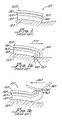
- Electrode 10 in accordance with the present invention as illustrated in Figures 2 and 3 which generally includes a conductive flexible member 12 having a top side 14 and a bottom side 16.
- the conductive flexible member may be a conductive fabric and is described in U.S. 4,722,354 and U.S. 4,708,149 to Axelgaard which provide a description of the flexible conductive fabric.
- a non-conductive flexible oversize sheet 26 covers the conductive flexible member 12 along with the connector 20 and the sheet 26 may be adhered to the flexible member 12 with a central adhesive layer 28 which also holds the lead wire 22 in contact with the member 12.
- the adhesive 28 is preferably a hot melt glue made by Bostick Findley, Borden or 3M. Moisture is prevented by sealing the central adhesive 28 and conductive adhesive 44 by a concentric perimeter adhesive 28a, as hereinabove noted.
- sheet 26 has dimensions greater than overall dimensions of the member 12 resulting in an edge, or perimeter, 26a which overlaps the member 12, see Figure 3 .
- This structure eliminates the need for alignment of the sheet 26 with the member along their peripheries as with the prior art.
- the perimeter adhesive 28a covers the edge 26a and is preferably a soft skin silicone adhesive available from DOW Corning. This adhesive is non hydrophilic and consequently provides a moisture resistant seal which is particularly important in high humidity environment such as neonatal incubators.
- the oversized sheet 26 enables the electrode 10 to be sealed along the perimeter 26a to a user's skin and stabilizes the electrode in a vertically aligned configuration to prevent "rolling" action of the prior art electrode 10P, shown in Figure 1a and 1b .
- This enables activity by a user and further enables bathing or showering by the user without degradation of the electrode/skin coupling. Water is prevented from entering the electrode 10 under the sheet 26 by the perimeter adhesive 28a.
- the lead wire 22 may be of any suitable conductive material.
- a conductive hydrogel adhesive 44 may be utilized for adhering the electrode 10 to a patient's skin, not shown.
- a suitable adhesive is described in U.S. 6,038,464 .
- a gap 46 further prevents environmental contamination with the hydrogel adhesive 44.
- a plastic, paper, or other suitable carrier 48 along with a release coating 50 may be provided in order to prevent inadvertent and/or premature adhesion of the patients' skin or other object to the hydrogel.
- the plastic carrier 48 and release coating 50 is removed prior to application of the electrode 10 to the patients' skin.
- Shown in Figure 4 is another electrode embodiment 54 which includes a conductive flexible member 56 having a plurality of highly conductive ink patterns 60, 62, 64 disposed on a bottom side 68 of the conductive member 56.
- the conductive ink patterns 60, 62 and 64 may be of various shapes and grid patterns in order to customize the electrical conductivity of the electrode 54 beneath the pattern 60, 62, 64.
- the spaced apart pattern 60, 62 and 64 act as separate electrodes and communicate with lead wires 72, 74, 76 respectively, which are attached to a top side (not shown in Figure 4 ) of the conductive member 56 as illustrated in Figure 2 with the description of the electrode embodiment 10.
- the connector 72, 74, 76 are placed over the ink patterns 60, 62, 64.
- the lead wires 72, 74, 76 can be placed anywhere between the borders 80, 82, 84 of the ink patterns 60, 62, 64 since the current distribution across the electrode gel 44 is independently controlled as hereinabove noted.
Claims (10)
- Electrode médicale (10) comprenant :un élément flexible conducteur (12) ayant un côté supérieur (14) et un côté inférieur (16),un connecteur (20) en contact avec l'élément flexible conducteur (12) pour établir un contact électrique avec un appareil externe,une feuille flexible non conductrice (26) disposée sur le côté supérieur (14) de l'élément flexible conducteur (12),un adhésif central (28) destiné à lier ladite feuille flexible non conductrice (26) au côté supérieur (14) dudit élément flexible conducteur (12) et fixer ledit connecteur (20) audit côté supérieur (14) de l'élément flexible conducteur (12), etun adhésif conducteur (44), disposé sur le côté inférieur (16) de l'élément flexible conducteur (12) destiné à faire adhérer l'électrode (10) à la peau du patient,caractérisé en ce que la feuille flexible non conductrice (26) a des dimensions supérieures à l'élément flexible conducteur (12) provoquant un chevauchement de celui-ci par un périmètre de feuille (26a), l'électrode médicale (10) comprend en outre un adhésif périphérique (28a) disposé autour dudit adhésif central (28), sur le périmètre de feuille (26a) et permettant une étanchéité de l'électrode (10) sur la peau d'un utilisateur,l'adhésif central (28), l'adhésif périphérique (28a) et l'adhésif conducteur (44) comprennent chacun un type d'adhésif différent,l'adhésif périphérique (28a) est un adhésif non hydrophile, etl'adhésif conducteur (44) est disposé sur le côté inférieur (16) de l'élément flexible conducteur (12) suivant une relation écartée par rapport audit adhésif périphérique (44).
- Electrode selon la revendication 1 dans laquelle ledit adhésif conducteur (44) comprend un hydrogel conducteur et ledit adhésif périphérique (28a) comprend un adhésif au silicone.
- Electrode selon la revendication 1, dans lequel ledit élément flexible conducteur (12) comprend un tissu conducteur.
- Electrode selon la revendication 1 dans laquelle l'élément flexible conducteur (12) comprend une pluralité d'éléments flexibles conducteurs, et
dans laquelle le connecteur (20) comprend une pluralité de connecteurs, chaque connecteur de la pluralité de connecteurs étant en contact avec un élément flexible conducteur (12) correspondant de la pluralité d'éléments flexibles conducteurs. - Electrode selon la revendication 4 dans laquelle la feuille flexible non conductrice (26) comprend des dimensions supérieures à une dimension totale de la pluralité d'éléments flexibles conducteurs (12) en provoquant un chevauchement de ceux-ci par le périmètre de feuille (26a).
- Electrode selon la revendication 5 dans laquelle l'adhésif central (28) comprend une pluralité d'adhésifs centraux, chaque adhésif central de la pluralité d'adhésifs liant un élément flexible conducteur (12) correspondant de la pluralité d'éléments flexibles à la feuille flexible non conductrice (26).
- Electrode selon la revendication 6 dans laquelle l'adhésif conducteur (28) comprend une pluralité d'adhésifs conducteurs, chaque adhésif conducteur de la pluralité d'adhésifs conducteurs liant un côté inférieur (16) d'un élément flexible conducteur (12) correspondant de la pluralité d'éléments flexibles conducteurs suivant une relation écartée à l'adhésif périphérique (28a).
- Electrode selon la revendication 7 dans laquelle l'adhésif périphérique (28a) est disposé autour de la pluralité d'adhésifs centraux (28) sur le périmètre de feuille (26a).
- Electrode selon la revendication 2 dans laquelle l'adhésif central (28) comprend un adhésif central non conducteur.
- Electrode selon la revendication 9 dans laquelle l'adhésif central non conducteur comprend une colle thermofusible.
Applications Claiming Priority (3)
| Application Number | Priority Date | Filing Date | Title |
|---|---|---|---|
| US11/519,676 US7697998B2 (en) | 2006-01-20 | 2006-09-11 | Electrode with edge protection |
| US11/588,539 US7697999B2 (en) | 2003-02-06 | 2006-10-27 | Moisture resistant electrode with edge protection |
| PCT/US2007/077120 WO2008033669A2 (fr) | 2006-09-11 | 2007-08-29 | électrode résistant à l'humidité avec protection des bords |
Publications (3)
| Publication Number | Publication Date |
|---|---|
| EP2066395A2 EP2066395A2 (fr) | 2009-06-10 |
| EP2066395A4 EP2066395A4 (fr) | 2013-10-16 |
| EP2066395B1 true EP2066395B1 (fr) | 2016-02-10 |
Family
ID=39184451
Family Applications (1)
| Application Number | Title | Priority Date | Filing Date |
|---|---|---|---|
| EP07841554.4A Not-in-force EP2066395B1 (fr) | 2006-09-11 | 2007-08-29 | Électrode résistant à l'humidité avec protection des bords |
Country Status (4)
| Country | Link |
|---|---|
| US (1) | US7697999B2 (fr) |
| EP (1) | EP2066395B1 (fr) |
| JP (3) | JP2010502380A (fr) |
| WO (1) | WO2008033669A2 (fr) |
Families Citing this family (13)
| Publication number | Priority date | Publication date | Assignee | Title |
|---|---|---|---|---|
| US7697999B2 (en) * | 2003-02-06 | 2010-04-13 | Axelgaard Manufacturing Company, Ltd. | Moisture resistant electrode with edge protection |
| US20080161884A1 (en) * | 2004-12-23 | 2008-07-03 | Mark Chandler | Method and apparatus for treating or preventing a medical condition |
| US20100075532A1 (en) * | 2008-09-25 | 2010-03-25 | Tyco Healthcare Group Lp | Fluorescent Marker for Detecting Gel or Lack of Gel |
| US20100076294A1 (en) * | 2008-09-25 | 2010-03-25 | Tyco Healthcare Group Lp | System and Method of Prepping Skin Prior to Electrode Application |
| US20100072060A1 (en) * | 2008-09-25 | 2010-03-25 | Tyco Healthcare Group Lp | Biomedical Electrode and Method of Formation Thereof |
| EP2833785A4 (fr) | 2012-04-03 | 2015-10-28 | Altec Inc | Capteur biomédical conforme à profil bas jetable |
| WO2014071471A1 (fr) * | 2012-11-07 | 2014-05-15 | Oliveira De Souza E Silva Paulo Eug Nio | Henricus intensive care / neuromuscular electrical stimulator (henricus - soins intensifs / électrostimulateur neuromusculaire) |
| US10244986B2 (en) | 2013-01-23 | 2019-04-02 | Avery Dennison Corporation | Wireless sensor patches and methods of manufacturing |
| US10004421B2 (en) | 2013-09-13 | 2018-06-26 | Altec, Inc. | Disposable protective overlay covering for biomedical sensors |
| DE102016118001A1 (de) * | 2016-05-25 | 2017-11-30 | Teiimo Gmbh | Textilprodukt mit dehnbarer Elektrode und/oder außenseitiger Kontaktierung der Elektrode oder eines anderen Sensors, und Verfahren zu seiner Herstellung |
| EP3434323B1 (fr) | 2017-07-29 | 2020-04-08 | Hanno Voigt | Dispositif de stimulation électrique fonctionnelle sous l'eau |
| DK179927B1 (en) * | 2017-12-18 | 2019-10-09 | Innocon Medical Aps | SYSTEM FOR ELECTRICAL STIMULATION OF NERVES |
| US11006882B2 (en) * | 2018-06-15 | 2021-05-18 | Johnson Electric International AG | Medical sensor |
Family Cites Families (18)
| Publication number | Priority date | Publication date | Assignee | Title |
|---|---|---|---|---|
| JPH063533Y2 (ja) * | 1987-11-30 | 1994-02-02 | 株式会社クラレ | 電極用パッド |
| DK283789A (da) * | 1988-10-05 | 1990-04-06 | Niels Kornerup | Elektrisk generator, kompres og kompreskombination og system til behandling af saar ved elektrisk stimulering samt fremgangsmaade til behandling af saar |
| US5133356A (en) * | 1991-04-16 | 1992-07-28 | Minnesota Mining And Manufacturing Company | Biomedical electrode having centrally-positioned tab construction |
| US5269810A (en) * | 1992-06-19 | 1993-12-14 | W. L. Gore & Associates, Inc. | Patch electrode |
| US5450845A (en) * | 1993-01-11 | 1995-09-19 | Axelgaard; Jens | Medical electrode system |
| US5733324A (en) * | 1995-12-08 | 1998-03-31 | Ferrari; R. Keith | X-ray transmissive transcutaneous stimulating electrode |
| US5727550A (en) | 1996-04-09 | 1998-03-17 | Lectec Corporation | Dual purpose ultrasonic biomedical couplant pad and electrode |
| US6148233A (en) | 1997-03-07 | 2000-11-14 | Cardiac Science, Inc. | Defibrillation system having segmented electrodes |
| DE69934315T2 (de) * | 1998-07-31 | 2007-07-05 | First Water Ltd., Marlborough | Bioadhesive zusammensetzungen mit hydrophobe polymeren |
| US6687524B1 (en) | 1999-08-24 | 2004-02-03 | Cas Medical Systems, Inc | Disposable neonatal electrode for use in a high humidity environment |
| WO2002039894A1 (fr) | 2000-11-16 | 2002-05-23 | Axelgaard Manufacturing Company, Ltd. | Electrode a usage medical munie d'un detecteur a deux elements |
| US7078582B2 (en) * | 2001-01-17 | 2006-07-18 | 3M Innovative Properties Company | Stretch removable adhesive articles and methods |
| US6795722B2 (en) | 2001-06-18 | 2004-09-21 | Neotech Products, Inc. | Electrode sensor package and application to the skin of a newborn or infant |
| US6600957B2 (en) * | 2001-06-28 | 2003-07-29 | The Ludlow Company Lp | High-energy disposable medical stimulation electrode |
| US7324847B2 (en) * | 2003-02-06 | 2008-01-29 | Axelgaard Manufacturing Co., Ltd. | Reverse current controlling electrode |
| US7697999B2 (en) * | 2003-02-06 | 2010-04-13 | Axelgaard Manufacturing Company, Ltd. | Moisture resistant electrode with edge protection |
| US7479133B2 (en) * | 2003-06-30 | 2009-01-20 | Johnson & Johnson Consumer Companies, Inc. | Methods of treating acne and rosacea with galvanic generated electricity |
| GB2422549A (en) | 2005-02-01 | 2006-08-02 | Wound Solutions Ltd | Flexible electrodes comprising a honey-comb mesh and integrated wound stimulation treatment devices |
-
2006
- 2006-10-27 US US11/588,539 patent/US7697999B2/en not_active Expired - Lifetime
-
2007
- 2007-08-29 JP JP2009527496A patent/JP2010502380A/ja active Pending
- 2007-08-29 EP EP07841554.4A patent/EP2066395B1/fr not_active Not-in-force
- 2007-08-29 WO PCT/US2007/077120 patent/WO2008033669A2/fr active Application Filing
-
2013
- 2013-05-09 JP JP2013099088A patent/JP5607785B2/ja active Active
-
2014
- 2014-08-26 JP JP2014171284A patent/JP5970036B2/ja active Active
Also Published As
| Publication number | Publication date |
|---|---|
| JP5607785B2 (ja) | 2014-10-15 |
| EP2066395A4 (fr) | 2013-10-16 |
| JP2010502380A (ja) | 2010-01-28 |
| EP2066395A2 (fr) | 2009-06-10 |
| US20070043417A1 (en) | 2007-02-22 |
| JP2013208442A (ja) | 2013-10-10 |
| US7697999B2 (en) | 2010-04-13 |
| JP5970036B2 (ja) | 2016-08-17 |
| WO2008033669A2 (fr) | 2008-03-20 |
| JP2014237045A (ja) | 2014-12-18 |
| WO2008033669A3 (fr) | 2008-11-13 |
Similar Documents
| Publication | Publication Date | Title |
|---|---|---|
| EP2066395B1 (fr) | Électrode résistant à l'humidité avec protection des bords | |
| US7697998B2 (en) | Electrode with edge protection | |
| US7695430B2 (en) | Reverse current controlling electrode with oversize backing | |
| EP2340080B1 (fr) | Electrode en forme de chaîne | |
| US8874231B2 (en) | Customizable medical electrode | |
| US8320988B2 (en) | Multi-electrode strung on a common connector | |
| EP2160131B1 (fr) | Electrode medicale avec des decoupures pour regler la conductivite laterale | |
| US6745082B2 (en) | Current-controlling electrode with adjustable contact area | |
| US9072884B2 (en) | Differential diameter electrode | |
| US5843155A (en) | Current-controlling electrode system | |
| EP2814562B1 (fr) | Électrode de commande de courant double face |
Legal Events
| Date | Code | Title | Description |
|---|---|---|---|
| PUAI | Public reference made under article 153(3) epc to a published international application that has entered the european phase |
Free format text: ORIGINAL CODE: 0009012 |
|
| AK | Designated contracting states |
Kind code of ref document: A2 Designated state(s): AT BE BG CH CY CZ DE DK EE ES FI FR GB GR HU IE IS IT LI LT LU LV MC MT NL PL PT RO SE SI SK TR |
|
| AX | Request for extension of the european patent |
Extension state: AL BA HR MK RS |
|
| 17P | Request for examination filed |
Effective date: 20090513 |
|
| RBV | Designated contracting states (corrected) |
Designated state(s): AT BE BG CH CY CZ DE DK EE ES FI FR GB GR HU IE IS IT LI LT LU LV MC MT NL PL PT RO SE SI SK TR |
|
| DAX | Request for extension of the european patent (deleted) | ||
| A4 | Supplementary search report drawn up and despatched |
Effective date: 20130913 |
|
| RIC1 | Information provided on ipc code assigned before grant |
Ipc: A61N 1/04 20060101AFI20130909BHEP |
|
| GRAP | Despatch of communication of intention to grant a patent |
Free format text: ORIGINAL CODE: EPIDOSNIGR1 |
|
| INTG | Intention to grant announced |
Effective date: 20150820 |
|
| GRAS | Grant fee paid |
Free format text: ORIGINAL CODE: EPIDOSNIGR3 |
|
| GRAA | (expected) grant |
Free format text: ORIGINAL CODE: 0009210 |
|
| AK | Designated contracting states |
Kind code of ref document: B1 Designated state(s): AT BE BG CH CY CZ DE DK EE ES FI FR GB GR HU IE IS IT LI LT LU LV MC MT NL PL PT RO SE SI SK TR |
|
| REG | Reference to a national code |
Ref country code: GB Ref legal event code: FG4D |
|
| REG | Reference to a national code |
Ref country code: AT Ref legal event code: REF Ref document number: 774349 Country of ref document: AT Kind code of ref document: T Effective date: 20160215 Ref country code: CH Ref legal event code: EP |
|
| REG | Reference to a national code |
Ref country code: IE Ref legal event code: FG4D |
|
| REG | Reference to a national code |
Ref country code: DE Ref legal event code: R096 Ref document number: 602007044830 Country of ref document: DE |
|
| REG | Reference to a national code |
Ref country code: LT Ref legal event code: MG4D |
|
| REG | Reference to a national code |
Ref country code: NL Ref legal event code: MP Effective date: 20160210 |
|
| REG | Reference to a national code |
Ref country code: AT Ref legal event code: MK05 Ref document number: 774349 Country of ref document: AT Kind code of ref document: T Effective date: 20160210 |
|
| PG25 | Lapsed in a contracting state [announced via postgrant information from national office to epo] |
Ref country code: IT Free format text: LAPSE BECAUSE OF FAILURE TO SUBMIT A TRANSLATION OF THE DESCRIPTION OR TO PAY THE FEE WITHIN THE PRESCRIBED TIME-LIMIT Effective date: 20160210 Ref country code: FI Free format text: LAPSE BECAUSE OF FAILURE TO SUBMIT A TRANSLATION OF THE DESCRIPTION OR TO PAY THE FEE WITHIN THE PRESCRIBED TIME-LIMIT Effective date: 20160210 Ref country code: ES Free format text: LAPSE BECAUSE OF FAILURE TO SUBMIT A TRANSLATION OF THE DESCRIPTION OR TO PAY THE FEE WITHIN THE PRESCRIBED TIME-LIMIT Effective date: 20160210 Ref country code: GR Free format text: LAPSE BECAUSE OF FAILURE TO SUBMIT A TRANSLATION OF THE DESCRIPTION OR TO PAY THE FEE WITHIN THE PRESCRIBED TIME-LIMIT Effective date: 20160511 |
|
| PG25 | Lapsed in a contracting state [announced via postgrant information from national office to epo] |
Ref country code: AT Free format text: LAPSE BECAUSE OF FAILURE TO SUBMIT A TRANSLATION OF THE DESCRIPTION OR TO PAY THE FEE WITHIN THE PRESCRIBED TIME-LIMIT Effective date: 20160210 Ref country code: LT Free format text: LAPSE BECAUSE OF FAILURE TO SUBMIT A TRANSLATION OF THE DESCRIPTION OR TO PAY THE FEE WITHIN THE PRESCRIBED TIME-LIMIT Effective date: 20160210 Ref country code: NL Free format text: LAPSE BECAUSE OF FAILURE TO SUBMIT A TRANSLATION OF THE DESCRIPTION OR TO PAY THE FEE WITHIN THE PRESCRIBED TIME-LIMIT Effective date: 20160210 Ref country code: PT Free format text: LAPSE BECAUSE OF FAILURE TO SUBMIT A TRANSLATION OF THE DESCRIPTION OR TO PAY THE FEE WITHIN THE PRESCRIBED TIME-LIMIT Effective date: 20160613 Ref country code: LV Free format text: LAPSE BECAUSE OF FAILURE TO SUBMIT A TRANSLATION OF THE DESCRIPTION OR TO PAY THE FEE WITHIN THE PRESCRIBED TIME-LIMIT Effective date: 20160210 Ref country code: IS Free format text: LAPSE BECAUSE OF FAILURE TO SUBMIT A TRANSLATION OF THE DESCRIPTION OR TO PAY THE FEE WITHIN THE PRESCRIBED TIME-LIMIT Effective date: 20160610 Ref country code: SE Free format text: LAPSE BECAUSE OF FAILURE TO SUBMIT A TRANSLATION OF THE DESCRIPTION OR TO PAY THE FEE WITHIN THE PRESCRIBED TIME-LIMIT Effective date: 20160210 Ref country code: PL Free format text: LAPSE BECAUSE OF FAILURE TO SUBMIT A TRANSLATION OF THE DESCRIPTION OR TO PAY THE FEE WITHIN THE PRESCRIBED TIME-LIMIT Effective date: 20160210 |
|
| REG | Reference to a national code |
Ref country code: FR Ref legal event code: PLFP Year of fee payment: 10 |
|
| PG25 | Lapsed in a contracting state [announced via postgrant information from national office to epo] |
Ref country code: DK Free format text: LAPSE BECAUSE OF FAILURE TO SUBMIT A TRANSLATION OF THE DESCRIPTION OR TO PAY THE FEE WITHIN THE PRESCRIBED TIME-LIMIT Effective date: 20160210 Ref country code: EE Free format text: LAPSE BECAUSE OF FAILURE TO SUBMIT A TRANSLATION OF THE DESCRIPTION OR TO PAY THE FEE WITHIN THE PRESCRIBED TIME-LIMIT Effective date: 20160210 |
|
| REG | Reference to a national code |
Ref country code: DE Ref legal event code: R097 Ref document number: 602007044830 Country of ref document: DE |
|
| PG25 | Lapsed in a contracting state [announced via postgrant information from national office to epo] |
Ref country code: RO Free format text: LAPSE BECAUSE OF FAILURE TO SUBMIT A TRANSLATION OF THE DESCRIPTION OR TO PAY THE FEE WITHIN THE PRESCRIBED TIME-LIMIT Effective date: 20160210 Ref country code: CZ Free format text: LAPSE BECAUSE OF FAILURE TO SUBMIT A TRANSLATION OF THE DESCRIPTION OR TO PAY THE FEE WITHIN THE PRESCRIBED TIME-LIMIT Effective date: 20160210 Ref country code: SK Free format text: LAPSE BECAUSE OF FAILURE TO SUBMIT A TRANSLATION OF THE DESCRIPTION OR TO PAY THE FEE WITHIN THE PRESCRIBED TIME-LIMIT Effective date: 20160210 |
|
| PLBE | No opposition filed within time limit |
Free format text: ORIGINAL CODE: 0009261 |
|
| STAA | Information on the status of an ep patent application or granted ep patent |
Free format text: STATUS: NO OPPOSITION FILED WITHIN TIME LIMIT |
|
| PG25 | Lapsed in a contracting state [announced via postgrant information from national office to epo] |
Ref country code: BE Free format text: LAPSE BECAUSE OF FAILURE TO SUBMIT A TRANSLATION OF THE DESCRIPTION OR TO PAY THE FEE WITHIN THE PRESCRIBED TIME-LIMIT Effective date: 20160210 |
|
| 26N | No opposition filed |
Effective date: 20161111 |
|
| PG25 | Lapsed in a contracting state [announced via postgrant information from national office to epo] |
Ref country code: BG Free format text: LAPSE BECAUSE OF FAILURE TO SUBMIT A TRANSLATION OF THE DESCRIPTION OR TO PAY THE FEE WITHIN THE PRESCRIBED TIME-LIMIT Effective date: 20160510 Ref country code: SI Free format text: LAPSE BECAUSE OF FAILURE TO SUBMIT A TRANSLATION OF THE DESCRIPTION OR TO PAY THE FEE WITHIN THE PRESCRIBED TIME-LIMIT Effective date: 20160210 |
|
| PG25 | Lapsed in a contracting state [announced via postgrant information from national office to epo] |
Ref country code: MC Free format text: LAPSE BECAUSE OF FAILURE TO SUBMIT A TRANSLATION OF THE DESCRIPTION OR TO PAY THE FEE WITHIN THE PRESCRIBED TIME-LIMIT Effective date: 20160210 |
|
| REG | Reference to a national code |
Ref country code: CH Ref legal event code: PL |
|
| PG25 | Lapsed in a contracting state [announced via postgrant information from national office to epo] |
Ref country code: CH Free format text: LAPSE BECAUSE OF NON-PAYMENT OF DUE FEES Effective date: 20160831 Ref country code: LI Free format text: LAPSE BECAUSE OF NON-PAYMENT OF DUE FEES Effective date: 20160831 |
|
| REG | Reference to a national code |
Ref country code: IE Ref legal event code: MM4A |
|
| PG25 | Lapsed in a contracting state [announced via postgrant information from national office to epo] |
Ref country code: IE Free format text: LAPSE BECAUSE OF NON-PAYMENT OF DUE FEES Effective date: 20160829 |
|
| REG | Reference to a national code |
Ref country code: FR Ref legal event code: PLFP Year of fee payment: 11 |
|
| PG25 | Lapsed in a contracting state [announced via postgrant information from national office to epo] |
Ref country code: LU Free format text: LAPSE BECAUSE OF NON-PAYMENT OF DUE FEES Effective date: 20160829 |
|
| PG25 | Lapsed in a contracting state [announced via postgrant information from national office to epo] |
Ref country code: HU Free format text: LAPSE BECAUSE OF FAILURE TO SUBMIT A TRANSLATION OF THE DESCRIPTION OR TO PAY THE FEE WITHIN THE PRESCRIBED TIME-LIMIT; INVALID AB INITIO Effective date: 20070829 Ref country code: CY Free format text: LAPSE BECAUSE OF FAILURE TO SUBMIT A TRANSLATION OF THE DESCRIPTION OR TO PAY THE FEE WITHIN THE PRESCRIBED TIME-LIMIT Effective date: 20160210 |
|
| PG25 | Lapsed in a contracting state [announced via postgrant information from national office to epo] |
Ref country code: MT Free format text: LAPSE BECAUSE OF NON-PAYMENT OF DUE FEES Effective date: 20160831 Ref country code: TR Free format text: LAPSE BECAUSE OF FAILURE TO SUBMIT A TRANSLATION OF THE DESCRIPTION OR TO PAY THE FEE WITHIN THE PRESCRIBED TIME-LIMIT Effective date: 20160210 |
|
| REG | Reference to a national code |
Ref country code: FR Ref legal event code: PLFP Year of fee payment: 12 |
|
| PGFP | Annual fee paid to national office [announced via postgrant information from national office to epo] |
Ref country code: FR Payment date: 20210825 Year of fee payment: 15 |
|
| PGFP | Annual fee paid to national office [announced via postgrant information from national office to epo] |
Ref country code: GB Payment date: 20210827 Year of fee payment: 15 Ref country code: DE Payment date: 20210827 Year of fee payment: 15 |
|
| REG | Reference to a national code |
Ref country code: DE Ref legal event code: R119 Ref document number: 602007044830 Country of ref document: DE |
|
| GBPC | Gb: european patent ceased through non-payment of renewal fee |
Effective date: 20220829 |
|
| PG25 | Lapsed in a contracting state [announced via postgrant information from national office to epo] |
Ref country code: FR Free format text: LAPSE BECAUSE OF NON-PAYMENT OF DUE FEES Effective date: 20220831 Ref country code: DE Free format text: LAPSE BECAUSE OF NON-PAYMENT OF DUE FEES Effective date: 20230301 |
|
| PG25 | Lapsed in a contracting state [announced via postgrant information from national office to epo] |
Ref country code: GB Free format text: LAPSE BECAUSE OF NON-PAYMENT OF DUE FEES Effective date: 20220829 |