EP2066151A2 - Beleuchtungsansteuerungsvorrichtung und Beleuchtungssystem damit - Google Patents
Beleuchtungsansteuerungsvorrichtung und Beleuchtungssystem damit Download PDFInfo
- Publication number
- EP2066151A2 EP2066151A2 EP08165677A EP08165677A EP2066151A2 EP 2066151 A2 EP2066151 A2 EP 2066151A2 EP 08165677 A EP08165677 A EP 08165677A EP 08165677 A EP08165677 A EP 08165677A EP 2066151 A2 EP2066151 A2 EP 2066151A2
- Authority
- EP
- European Patent Office
- Prior art keywords
- signal
- lighting
- controlling data
- driving device
- lighting device
- Prior art date
- Legal status (The legal status is an assumption and is not a legal conclusion. Google has not performed a legal analysis and makes no representation as to the accuracy of the status listed.)
- Granted
Links
Images




Classifications
-
- H—ELECTRICITY
- H05—ELECTRIC TECHNIQUES NOT OTHERWISE PROVIDED FOR
- H05B—ELECTRIC HEATING; ELECTRIC LIGHT SOURCES NOT OTHERWISE PROVIDED FOR; CIRCUIT ARRANGEMENTS FOR ELECTRIC LIGHT SOURCES, IN GENERAL
- H05B47/00—Circuit arrangements for operating light sources in general, i.e. where the type of light source is not relevant
- H05B47/10—Controlling the light source
- H05B47/175—Controlling the light source by remote control
- H05B47/18—Controlling the light source by remote control via data-bus transmission
- H05B47/184—Controlling the light source by remote control via data-bus transmission using digital multiplexed [DMX] communication protocols
-
- G—PHYSICS
- G05—CONTROLLING; REGULATING
- G05B—CONTROL OR REGULATING SYSTEMS IN GENERAL; FUNCTIONAL ELEMENTS OF SUCH SYSTEMS; MONITORING OR TESTING ARRANGEMENTS FOR SUCH SYSTEMS OR ELEMENTS
- G05B2219/00—Program-control systems
- G05B2219/20—Pc systems
- G05B2219/21—Pc I-O input output
- G05B2219/21039—Followers, modules in daisy chain, each handles control data, transmits to next
Definitions
- the present invention relates to a driving device, and more particularly to an address-free lighting driving device and a lighting system thereof.
- the DMX512 communication protocol is developed by United States Institute fo r Theatre Technology (USITT) and used for controlling a light modulator by using a standard digital interface for stage controlling. Because of the characteristics of simplicity, reliability, and flexibility, the DMX512 has quickly become the mostly selected protocol under a situation of sufficient budget expense.
- USITT United States Institute fo r Theatre Technology
- the DMX512 is mostly applied to stage lighting control, in which it is necessary to set ID addresses for lighting devices in advance, and then the lighting change is modulated according to the ID addresses, so as to show a content transmitted by the DMX512 controller.
- the ID addresses are set and adjusted by a dip switch, or the ID address of each DMX control element is electronically set by means of communication transmission.
- FIG. 1A is a schematic view of connections of a lighting device in the prior art.
- a first lighting device 10 a second lighting device 20, and a third lighting device 30 are connected in parallel.
- FIG 1B is a schematic view of a DMX512 signal.
- the DMX512 signal received by each lighting device is the same, in which the DMX512 signal includes an initial signal 11, a first lighting device controlling data 12, a second lighting device controlling data 13, and a third lighting device controlling data 14.
- each lighting device obtains the corresponding lighting device controlling data respectively, such that an ON or OFF state of the lighting device is controlled.
- the lighting device may be installed at various positions (for example, under water, above water, on a wall surface, or hanging at a high position). If the dip-switch adjustment setting manner is adopted, the setting process may be quite inconvenient. Even if the setting position of the lighting device enables the ID address to be set easily, it is possible to result in false actions of the lighting device due to an error in the setting of the ID address.
- the present invention is directed to a lighting driving device and a lighting system thereof.
- Each lighting device is serially connected, and each lighting device is made to obtain respective lighting device controlling data in sequence, so that an actuation (for example, ON or OFF) of each lighting device is controlled, and thus the lighting device is driven without addressing, thereby improving the using convenience of the lighting system.
- the lighting driving device includes a first signal converter, a signal processor, and a lighting driving unit.
- the first signal converter carries a serial signal, and converts the serial signal to a digital signal, in which the first signal converter may be, for example, an RS-485 to transistor-transistor-logic (TTL) signal converter.
- the signal processor receives the digital signal output by the signal converter, decodes the digital signal to obtain a controlling data, and determines whether to transmit the serial signal to another lighting driving device or not according to the digital signal, in which the signal processor is a DMX512 signal decoder.
- the lighting driving unit outputs a driving signal to the lighting device according to the controlling data, so as to control an actuation (for example, ON or OFF) of the lighting device.
- a lighting system which includes a signal generator, for generating a serial signal including a plurality of lighting device controlling data; and a plurality of serially-connected lighting devices.
- Each lighting device includes a lighting driving device, and the lighting driving device controls an actuation of the lighting device where the lighting driving device is adopted according to the lighting device controlling data obtained by decoding.
- various lighting devices are serially connected together and a lighting driving device is disposed on each lighting device, such that each lighting device obtains their respective lighting device controlling data according to a serial connection sequence, and thus the ON or OFF state of each lighting device is controlled without setting the ID addresses in advance. Therefore, the lighting devices are driven without addressing, and the using convenience of the lighting system is further enhanced.
- FIG. 2 is a system block diagram of a lighting driving device according to the present invention.
- the lighting driving device of the present invention includes a serial transmission interface 40, a first signal converter 50, a signal processor 60, and a lighting driving unit 70.
- the serial transmission interface 40 is used to receive a signal or data in a serial transmission format, for example, a differential signal.
- the serial transmission interface 40 may be, for example, an RS-422 interface or an RS-485 interface.
- the first signal converter 50 is electrically connected to the serial transmission interface 40, for receiving a serial signal output by the serial transmission interface 40, and converting the serial signal to a digital signal.
- the digital signal is preferably a standard DMX512 signal.
- the first signal converter 50 is preferably an RS-485 to TTL signal converter.
- the serial transmission interface 40 of the present invention may be omitted, and instead, the serial signal is directly carried by the first signal converter 50.
- the signal processor 60 is electrically connected to the first signal converter 50, for receiving the digital signal output by the first signal converter 50, and decoding the digital signal to obtain a lighting device controlling data.
- the signal processor 60 determines whether to transmit the serial signal output by the serial transmission interface 40 to another lighting driving device (not shown) or not according to the digital signal.
- the signal processor 60 may be, for example, a DMX512 signal decoder or a micro control unit (MCU).
- the digital signal includes an initial signal, a blank data, and a plurality of lighting device controlling data.
- the signal processor 60 continues to transmit the initial signal and the blank data to another lighting driving device simultaneously; once receiving a first controlling data in the plurality of lighting device controlling data, the signal processor 60 synchronously transmits a null signal to the another lighting driving device; and once receiving the subsequent controlling data in the plurality of lighting device controlling data after the first controlling data, the signal processor 60 continues to transmit the subsequent controlling data after the first controlling data to the another lighting driving device.
- the lighting device controlling data after the first controlling data refers to the second controlling data and the residual lighting device controlling data. Since the lighting devices of the present invention are serially connected, the DMX512 signal may be distorted after a multistage signal converting process. Therefore, before the signal processor 60 in each stage outputs the digital signal to the second signal converter 51 (as shown in FIG. 3 ), a signal waveform of the output digital signal is further corrected, so as to solve the signal distortion problem resulted from signal conversion.
- the lighting driving unit 70 is electrically connected to the signal processor 60, for outputting a driving signal to the lighting device according to the controlling data, so as to control an actuation (for example, ON or OFF) of the lighting device.
- the lighting driving unit 70 includes a pulse width modulator (PWM) and a driver, in which the driver is preferably a current driver.
- PWM pulse width modulator
- the switch 80 is electrically connected to the serial transmission interface 40 and the signal processor 60, and the signal processor 60 controls an ON/OFF motion of the switch 80, so as to determine whether to transmit the serial signal output by the serial transmission interface 40 to the circuit in next stage or not.
- the switch 80 is in an ON state, the serial signal is transmitted to the circuit in the next stage.
- FIG. 3 is a circuit block diagram of a lighting driving device according to the present invention.
- the lighting driving device of the present invention includes a serial transmission interface 40, a first signal converter 50, a second signal converter 51, a signal processor 60, and a lighting driving unit 70.
- the serial transmission interface 40 is used to receive a signal or data in a serial transmission format, for example, a differential signal.
- the serial transmission interface 40 may be, for example, an RS-422 interface or an RS-485 interface.
- the serial transmission interface 40 is preferably the RS-485 interface.
- the first signal converter 50 is electrically connected to the serial transmission interface 40, for receiving a serial signal output by the serial transmission interface 40, and converting the serial signal to a digital signal.
- the digital signal is preferably a standard DMX512 signal.
- the first signal converter 50 is preferably an RS-485 to TTL signal converter.
- the serial transmission interface 40 of the present invention may be omitted, and instead, the serial signal is directly carried by the first signal converter 50.
- the second signal converter 51 is electrically connected to the signal processor 60, for receiving the digital signal output by the signal processor 60, and converting the digital signal to the serial signal.
- the second signal converter 51 is preferably a TTL to RS-485 signal converter.
- the signal processor 60 is electrically connected to the first signal converter 50, for receiving the digital signal output by the first signal converter 50, and decoding the digital signal to obtain a lighting device controlling data.
- the signal processor 60 determines whether to transmit the serial signal output by the serial transmission interface 40 to another lighting driving device (not shown) or not according to the digital signal.
- the signal processor 60 may be, for example, a DMX512 signal decoder.
- the lighting driving unit 70 is electrically connected to the signal processor 60, for outputting a driving signal to the lighting device according to the controlling data, so as to control an actuation (for example, ON or OFF) of the lighting device.
- the lighting driving unit 70 includes a red signal PWM unit 71, a green signal PWM unit 72, a blue signal PWM unit 73, a red signal driver 74, a green signal driver 75, and a blue signal driver 76.
- the switch 80 is electrically connected to the serial transmission interface 40 and the signal processor 60, and the signal processor 60 controls an ON/OFF motion of the switch 80, so as to determine whether to transmit the serial signal output by the serial transmission interface 40 to the second signal converter 51 or not.
- the switch 80 is in an ON state, the serial signal is transmitted to the second signal converter 51.
- FIG. 4 is a schematic view of a connection circuit of a lighting device according to the present invention. As shown in FIG. 4 , the first lighting device 10, the second lighting device 20, and the third lighting device 30 are serially connected. Each lighting device preferably includes at least one light-emitting diode (LED) lamp or other illumination lamps.
- LED light-emitting diode
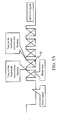
- FIGs. 5A , 5B , and 5C are respectively schematic views of a DMX512 signal of each lighting device according to the present invention.
- the signal processor 60 turns off a data backward transmission function, and when obtaining the first lighting device controlling data 12, the signal processor 60 synchronously transmits a null signal to the second lighting device 20, and turns on the data backward transmission function, so as to continue to transmit the residual lighting device controlling data (for example, the second lighting device controlling data 13 and the third lighting device controlling data 14) subsequent to the first lighting device controlling data to the second lighting device 20.
- the second lighting device 20 continues to transmit the initial signal and the blank data to the third lighting device 30 simultaneously.
- the signal processor 60 turns off a data backward transmission function, and when obtaining the second lighting device controlling data 13, the signal processor 60 synchronously transmits a null signal to the third lighting device 30, and turns on the data backward transmission function, so as to continue to transmit the residual lighting device controlling data (for example, the third lighting device controlling data 14) subsequent to the first lighting device controlling data to the third lighting device 30.
- the third lighting device 30 continues to transmit the initial signal and the blank data to the next lighting device simultaneously.
- the signal processor 60 turns off a data backward transmission function, and when obtaining the third lighting device controlling data 14, the signal processor 60 synchronously transmits a null signal to the next lighting device, and turns on the data backward transmission function, so as to continue to transmit the residual lighting device controlling data subsequent to the first lighting device controlling data to the next lighting device, and so forth.
- each lighting device is stopped from transmitting the DMX512 signal to the next lighting device. After obtaining the lighting device controlling data, each lighting device continues to transmit the DMX512 signal to the next lighting device. In other words, each lighting device obtains their respective lighting device controlling data according to the serial connection sequence, so that the ON or OFF state of each lighting device is controlled without setting the ID address in advance.
- FIG. 6 is a block diagram of a lighting system according to the present invention.
- a lighting system 200 of the present invention includes a plurality of lighting devices (for example, a lighting device 15, a lighting device 25, and a lighting device 35) and a signal generator 90.
- the connecting manner between the lighting device 15, the lighting device 25, and the lighting device 35 is as shown in FIG. 4 .
- Each lighting device includes a lighting driving device 100, and the lighting driving device 100 is as shown in FIG. 3 .
- the signal generator 90 is used to generate a serial signal including a lighting device controlling data to the lighting driving device 100 of the lighting device 15.
- Each lighting driving device 100 receives and decodes the serial signal, so as to obtain a lighting device controlling data corresponding to the lighting device.
- Each lighting driving device 100 controls the actuation (for example, ON or OFF) of the lighting device 15, the lighting device 25, and the lighting device 35 where the lighting driving device 100 is adopted according to the corresponding lighting device controlling data. After obtaining the lighting device controlling data in the serial signal, the lighting driving device 100 of the lighting device 15 transmits the serial signal to the lighting driving device 100 of the lighting device 25. After obtaining the lighting device controlling data in the serial signal, the lighting driving device 100 of the lighting device 25 transmits the serial signal to the lighting driving device 100 of the lighting device 35, and so forth.
- the lighting devices are serially connected together, and a lighting driving device is disposed on each lighting device, such that each lighting device obtains their respective lighting device controlling data according to the serial connection sequence, and thus the ON or OFF of each lighting device is controlled without setting the ID address in advance. Therefore, the lighting devices are driven without addressing, and the using convenience of the lighting system is further enhanced.
Landscapes
- Circuit Arrangement For Electric Light Sources In General (AREA)
- Arrangements For Transmission Of Measured Signals (AREA)
- Endoscopes (AREA)
Applications Claiming Priority (1)
| Application Number | Priority Date | Filing Date | Title |
|---|---|---|---|
| TW096143094A TW200922377A (en) | 2007-11-14 | 2007-11-14 | Light driving device and light system thereof |
Publications (3)
| Publication Number | Publication Date |
|---|---|
| EP2066151A2 true EP2066151A2 (de) | 2009-06-03 |
| EP2066151A3 EP2066151A3 (de) | 2010-10-27 |
| EP2066151B1 EP2066151B1 (de) | 2012-10-24 |
Family
ID=40433763
Family Applications (1)
| Application Number | Title | Priority Date | Filing Date |
|---|---|---|---|
| EP08165677A Not-in-force EP2066151B1 (de) | 2007-11-14 | 2008-10-02 | Beleuchtungsansteuerungsvorrichtung und Beleuchtungssystem damit |
Country Status (2)
| Country | Link |
|---|---|
| EP (1) | EP2066151B1 (de) |
| TW (1) | TW200922377A (de) |
Cited By (2)
| Publication number | Priority date | Publication date | Assignee | Title |
|---|---|---|---|---|
| CN102065081A (zh) * | 2010-11-21 | 2011-05-18 | 杨铁军 | 一种使用lid逻辑识别码的增强型dmx512通讯控制方法 |
| CN102487562A (zh) * | 2010-12-01 | 2012-06-06 | 中强光电股份有限公司 | 控制数字多工系统的方法 |
Family Cites Families (4)
| Publication number | Priority date | Publication date | Assignee | Title |
|---|---|---|---|---|
| US6738855B1 (en) * | 2000-01-14 | 2004-05-18 | National Semiconductor Corporation | Communication interface between a TTL microcontroller and a RS232 Device avoiding level translation |
| JP4467727B2 (ja) * | 2000-07-24 | 2010-05-26 | キヤノン株式会社 | 電子機器の接続方法およびその電子機器およびその動作処理プログラムを記憶した記憶媒体 |
| DE102004043197A1 (de) * | 2004-09-03 | 2006-03-09 | Lehmann, Erhard, Dipl.-Ing. (FH) | Verfahren zur Steuerung einer Beleuchtungsvorrichtung |
| US8115407B2 (en) * | 2006-11-29 | 2012-02-14 | Arc Solid-State Lighting Corporation | Address-free driving device and lighting fixture system |
-
2007
- 2007-11-14 TW TW096143094A patent/TW200922377A/zh not_active IP Right Cessation
-
2008
- 2008-10-02 EP EP08165677A patent/EP2066151B1/de not_active Not-in-force
Cited By (2)
| Publication number | Priority date | Publication date | Assignee | Title |
|---|---|---|---|---|
| CN102065081A (zh) * | 2010-11-21 | 2011-05-18 | 杨铁军 | 一种使用lid逻辑识别码的增强型dmx512通讯控制方法 |
| CN102487562A (zh) * | 2010-12-01 | 2012-06-06 | 中强光电股份有限公司 | 控制数字多工系统的方法 |
Also Published As
| Publication number | Publication date |
|---|---|
| EP2066151B1 (de) | 2012-10-24 |
| EP2066151A3 (de) | 2010-10-27 |
| TW200922377A (en) | 2009-05-16 |
| TWI369157B (de) | 2012-07-21 |
Similar Documents
| Publication | Publication Date | Title |
|---|---|---|
| EP2796007B1 (de) | Stromleitungskommunikationssteuerung von beleuchtungsarmaturen mit leuchtdioden (leds) | |
| US10098205B2 (en) | Configurable lighting devices under broadcast control | |
| CN101523986A (zh) | 用于操作照明装置的操作设备及方法 | |
| US9320119B2 (en) | System-voltage transmission branch of an interface of an operating device for light-emitting means | |
| JP2010509726A (ja) | Led照明具のための外部マイクロコントローラ、内部コントローラを備えるled照明具及びled照明システム | |
| US8115407B2 (en) | Address-free driving device and lighting fixture system | |
| TW200945944A (en) | Power supply apparatus for lighting device | |
| CN110505731A (zh) | 发光二极管驱动器,发光二极管模块和相应的系统 | |
| JP6504448B2 (ja) | 変調装置および照明器具 | |
| US10433377B2 (en) | Control circuit for modulating an analog dimming command signal | |
| EP2066151B1 (de) | Beleuchtungsansteuerungsvorrichtung und Beleuchtungssystem damit | |
| CN101453807B (zh) | 灯光驱动装置及其灯光系统 | |
| EP3562272B1 (de) | Antriebssystem | |
| WO2012009622A2 (en) | Powerline communication control of light emitting diode (led) lighting fixtures | |
| US20150028757A1 (en) | Single wire lighting driver control | |
| CN109688657B (zh) | 主从控制灯具组件 | |
| JP2009054585A (ja) | 群管理型照明制御システム | |
| JP2016523428A (ja) | 照明システム及びその位相角信号伝送装置 | |
| KR20100010184U (ko) | 구동회로가 내장된 소켓부를 가지는 엘이디램프 | |
| CN105072759B (zh) | 可调光调色灯饰 | |
| JP2020502750A5 (de) | ||
| TWM488822U (zh) | 直控式ZigBee無線照明系統 | |
| KR20090104724A (ko) | 조명 기구의 급전 장치 | |
| TWM644337U (zh) | 燈具以及調光控制系統 | |
| HK40090338A (zh) | 线性照明装置 |
Legal Events
| Date | Code | Title | Description |
|---|---|---|---|
| PUAI | Public reference made under article 153(3) epc to a published international application that has entered the european phase |
Free format text: ORIGINAL CODE: 0009012 |
|
| 17P | Request for examination filed |
Effective date: 20081029 |
|
| AK | Designated contracting states |
Kind code of ref document: A2 Designated state(s): AT BE BG CH CY CZ DE DK EE ES FI FR GB GR HR HU IE IS IT LI LT LU LV MC MT NL NO PL PT RO SE SI SK TR |
|
| AX | Request for extension of the european patent |
Extension state: AL BA MK RS |
|
| PUAL | Search report despatched |
Free format text: ORIGINAL CODE: 0009013 |
|
| AK | Designated contracting states |
Kind code of ref document: A3 Designated state(s): AT BE BG CH CY CZ DE DK EE ES FI FR GB GR HR HU IE IS IT LI LT LU LV MC MT NL NO PL PT RO SE SI SK TR |
|
| AX | Request for extension of the european patent |
Extension state: AL BA MK RS |
|
| AKX | Designation fees paid |
Designated state(s): DE FR GB IT |
|
| GRAP | Despatch of communication of intention to grant a patent |
Free format text: ORIGINAL CODE: EPIDOSNIGR1 |
|
| GRAS | Grant fee paid |
Free format text: ORIGINAL CODE: EPIDOSNIGR3 |
|
| GRAA | (expected) grant |
Free format text: ORIGINAL CODE: 0009210 |
|
| AK | Designated contracting states |
Kind code of ref document: B1 Designated state(s): DE FR GB IT |
|
| REG | Reference to a national code |
Ref country code: GB Ref legal event code: FG4D |
|
| REG | Reference to a national code |
Ref country code: DE Ref legal event code: R096 Ref document number: 602008019568 Country of ref document: DE Effective date: 20121220 |
|
| PG25 | Lapsed in a contracting state [announced via postgrant information from national office to epo] |
Ref country code: IT Free format text: LAPSE BECAUSE OF FAILURE TO SUBMIT A TRANSLATION OF THE DESCRIPTION OR TO PAY THE FEE WITHIN THE PRESCRIBED TIME-LIMIT Effective date: 20121024 |
|
| PLBE | No opposition filed within time limit |
Free format text: ORIGINAL CODE: 0009261 |
|
| STAA | Information on the status of an ep patent application or granted ep patent |
Free format text: STATUS: NO OPPOSITION FILED WITHIN TIME LIMIT |
|
| 26N | No opposition filed |
Effective date: 20130725 |
|
| REG | Reference to a national code |
Ref country code: DE Ref legal event code: R097 Ref document number: 602008019568 Country of ref document: DE Effective date: 20130725 |
|
| REG | Reference to a national code |
Ref country code: FR Ref legal event code: ST Effective date: 20140630 |
|
| PG25 | Lapsed in a contracting state [announced via postgrant information from national office to epo] |
Ref country code: FR Free format text: LAPSE BECAUSE OF NON-PAYMENT OF DUE FEES Effective date: 20131031 |
|
| PGFP | Annual fee paid to national office [announced via postgrant information from national office to epo] |
Ref country code: GB Payment date: 20170927 Year of fee payment: 10 |
|
| PGFP | Annual fee paid to national office [announced via postgrant information from national office to epo] |
Ref country code: DE Payment date: 20170927 Year of fee payment: 10 |
|
| REG | Reference to a national code |
Ref country code: DE Ref legal event code: R119 Ref document number: 602008019568 Country of ref document: DE |
|
| GBPC | Gb: european patent ceased through non-payment of renewal fee |
Effective date: 20181002 |
|
| PG25 | Lapsed in a contracting state [announced via postgrant information from national office to epo] |
Ref country code: DE Free format text: LAPSE BECAUSE OF NON-PAYMENT OF DUE FEES Effective date: 20190501 |
|
| PG25 | Lapsed in a contracting state [announced via postgrant information from national office to epo] |
Ref country code: GB Free format text: LAPSE BECAUSE OF NON-PAYMENT OF DUE FEES Effective date: 20181002 |