EP2065742B1 - Kollimiertes optisches System mit Bandschelle als Verschlussmechanismus - Google Patents
Kollimiertes optisches System mit Bandschelle als Verschlussmechanismus Download PDFInfo
- Publication number
- EP2065742B1 EP2065742B1 EP08170090A EP08170090A EP2065742B1 EP 2065742 B1 EP2065742 B1 EP 2065742B1 EP 08170090 A EP08170090 A EP 08170090A EP 08170090 A EP08170090 A EP 08170090A EP 2065742 B1 EP2065742 B1 EP 2065742B1
- Authority
- EP
- European Patent Office
- Prior art keywords
- sleeve
- housing
- lens cell
- slots
- monocular
- Prior art date
- Legal status (The legal status is an assumption and is not a legal conclusion. Google has not performed a legal analysis and makes no representation as to the accuracy of the status listed.)
- Not-in-force
Links
Images




Classifications
-
- G—PHYSICS
- G02—OPTICS
- G02B—OPTICAL ELEMENTS, SYSTEMS OR APPARATUS
- G02B23/00—Telescopes, e.g. binoculars; Periscopes; Instruments for viewing the inside of hollow bodies; Viewfinders; Optical aiming or sighting devices
- G02B23/16—Housings; Caps; Mountings; Supports, e.g. with counterweight
-
- G—PHYSICS
- G02—OPTICS
- G02B—OPTICAL ELEMENTS, SYSTEMS OR APPARATUS
- G02B7/00—Mountings, adjusting means, or light-tight connections, for optical elements
- G02B7/02—Mountings, adjusting means, or light-tight connections, for optical elements for lenses
- G02B7/023—Mountings, adjusting means, or light-tight connections, for optical elements for lenses permitting adjustment
-
- G—PHYSICS
- G02—OPTICS
- G02B—OPTICAL ELEMENTS, SYSTEMS OR APPARATUS
- G02B7/00—Mountings, adjusting means, or light-tight connections, for optical elements
- G02B7/02—Mountings, adjusting means, or light-tight connections, for optical elements for lenses
- G02B7/026—Mountings, adjusting means, or light-tight connections, for optical elements for lenses using retaining rings or springs
Definitions
- a vision-assisting device such as a monocular
- the device is collimated when the output optical axis matches the input optical axis such that the beam of light entering the device is parallel with the beam of light exiting the device.
- a technician typically aligns the optical axes through an iterative process that requires adjustment of the device, securement of the components of the device relative to one another, and determination of whether the device is satisfactorily collimated. If the device is not satisfactorily collimated, the technician must release some of the previously secured components of the device relative to one another and readjust the device.
- the present invention provides an optical system as defined in claim 1.
- the present invention provides a binocular comprising a frame and first and second monoculars having optical systems described above being separately releasably connected to the frame.
- a monocular 100 according to an exemplary embodiment of the present invention is shown.
- the exemplary monocular 100 can be used as a monocular or can be part of a night vision goggle (NVG) binocular 210, shown in Fig. 1 .
- NVG night vision goggle
- These devices are used to intensify ambient or infrared light for enhanced visibility in a darkened environment.
- monocular 100 is generally tubularly shaped, with an input end 102, which receives light from the external environment, and an output end 104, which transmits the intensified image to a user.
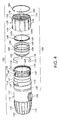
- the major components of monocular 100 are, from right to left, an eyepiece 106, an image intensifier tube 190 and an objective lens assembly 192, which are all carried in a housing 110.
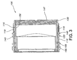
- eyepiece 106 includes an inner, or lens cell 150 disposed within an outer cell, or sleeve 130, which is partially disposed within housing 110.
- a focus ring 170 threadably engages housing 110 and is operative to longitudinally translate sleeve 130 and lens cell 150 with respect to housing 110. Such translation may be accomplished without rotating sleeve 130 and lens cell 150 with respect to housing 110.
- Eyepiece 106 is collimated during fabrication. Therefore, it is desired that sleeve 130 and lens cell 150 do not rotate relative to housing 110 or each other during operation, such as during focusing of eyepiece 106 by the user.
- Housing 110 is in the form of a generally tubular or cylindrical body 112.
- An output end 114 of housing 110 includes two elongated slots 116 formed in body 112.
- slots 116 are spaced from each other about 90 degrees around the outer perimeter or circumference of body 112. Those skilled in the art, however, will recognize that angles greater than or less than 90 degrees may be used.
- Slots 116 are sized to allow a tang 119 of a clip, such as a clip ring 118, shown in Figs. 3-6 , to be inserted therethrough to engage eccentric sleeve 130, as will be described later in detail herein. Referring to Fig.
- housing 110 also includes a thread 120 formed on the outer surface of body 112 to threadably engage focus ring 170.
- housing 110 includes a plurality of circumferentially spaced ridges 122 that extend generally parallel to each other and longitudinally along the length of input end 102. Ridges 122 assist the user in focusing monocular 100 during use.
- Eccentric sleeve 130 includes a generally cylindrical body defined by an outer surface 132 having a first, or outer, cylinder longitudinal axis 134 that extends perpendicularly out of the plane of the page of Fig. 7 , and an inner surface 136 that is eccentrically offset from outer surface 132.
- Inner surface 136 has a second, or inner, cylinder longitudinal axis 138 that extends perpendicularly out of the plane of the page of Fig. 7 .
- Inner cylinder longitudinal axis 138 is slightly offset from outer cylinder longitudinal axis 134 by a slight distance, such as, for example, approximately 0.5 millimeters, although those skilled in the art will recognize that the offset distance may be more or less than 0.5 millimeters.
- This offset creates a first eccentricity in sleeve 130 such that, when sleeve 130 is inserted into housing 110 and rotated within housing 110 during fabrication, inner cylinder longitudinal axis 138 shifts relative to outer cylinder longitudinal axis 134.
- sleeve 130 also includes a series of longitudinal slots 140 that are circumferentially spaced about outer surface 132.
- 40 slots 140 extend, evenly spaced, around outer surface 132.
- slots 140 may be rectangular, oval, oblong, or other shape that allows longitudinal translation of sleeve 130 with respect to housing 110. Slots 140 extend through outer surface 132 to inner surface 136.
- clip ring 118 is used to secure housing 110 to sleeve 130 to restrict rotation of sleeve 130 with respect to housing 110.
- clip ring 118 is an elongated piece of beryllium copper that is curved between a first end and a second end.
- Those skilled in the art will recognize that other materials, such as stainless steel, aluminum, or other suitable material, may be used instead of beryllium copper.
- the curvature matches the curvature of the exterior of housing 110.
- Clip ring 118 may have spring properties that enable clip ring 118 to be installed and removed repeatedly on housing 110 without damage.
- clip ring 118 has a length sufficient to extend about 270 degrees around the exterior of housing 110.
- Clip ring 118 includes tangs 119 that extend from each of the first and second end of clip ring 118, generally toward a radial center of clip ring 118.
- clip ring 118 may extend more or less than 270 degrees around the exterior of housing 110, so long as clip ring 118 is sufficiently long to allow tangs 119 to be inserted into elongated slot 116 as described below.
- Slots 140 are sized to accept and retain tang 119 with a sliding fit. As shown in Fig. 6 , when sleeve 130 is inserted into housing 110, sleeve 130 is aligned with housing 110 such that a selected one of slots 140 is aligned with each elongated slot 116. Each tang 119 is insertable through elongated slot 116 and into selsected slot 140 so that tang 119 is inserted into the selected slot 140. Slots 140 are longer than the width of tang 119 to allow sleeve 130 to translate axially within housing 110 into which each tang 119 is inserted. Such axial translation allows focusing of monocular 100 for an individual user. In addition to restricting rotation of sleeve 130 with respect to housing 110, clip ring 118 also serves as a mechanical stop for the axial translation of sleeve 130 with respect to housing 110.
- outer surface 132 includes a groove 141 that extends circumferentially around an output end of sleeve 130.
- Groove 141 is sized to accept and retain an o-ring (not shown) to seal a joint between outer surface 132 and housing 110 during assembly of monocular 100.
- Outer surface 132 also includes a lip 142 that engages focus ring 170 such that rotation of focus ring 170 longitudinally translates sleeve 130 relative to housing 110.
- Outer surface 132 further includes a groove 143 that extends circumferentially around an input end of sleeve 130.
- Groove 143 is sized to accept and retain a snap ring 184 inserted therein. Snap ring 184 secures focus ring 170 against lip 142.
- inner surface 136 of sleeve 130 also includes a plurality of teeth 144 that extend radially around an input lip 146 that extends inwardly from inner surface 136 toward inner cylinder longitudinal axis 138.
- a plurality of teeth 144 engage a plurality of mating teeth on lens cell 150, as will be described in detail later herein.
- inner surface 136 of sleeve 130 also includes an internal thread 147 that receives a locking ring 148.
- Locking ring 148 biases lens cell 150 against sleeve 130 and transmits longitudinal motion of sleeve 130 to lens cell 150 during focusing.
- Locking ring 148 includes an external thread 149 that engages internal thread 147 of inner surface 136.
- the output end of locking ring 148 also includes a pair of diametrically opposed slots 149a that are used to insert locking ring 148 into sleeve 130.
- An insertion tool (not shown) engages slots 149a. The insertion tool is rotated, thus rotating locking ring 148 and threading locking ring 148 onto sleeve 130.
- lens cell 150 includes a generally cylindrical body defined by an outer surface 152 having a lens cell central longitudinal axis 154 that extends perpendicularly out of the plane of the page of Fig. 9 , and an inner surface 156 that is eccentrically offset from outer surface 152.
- Inner surface 156 has an optical axis 158 that extends perpendicularly out of the plane of the page of Fig. 9 .
- Optical axis 158 is slightly offset from lens cell central longitudinal axis 154 by a slight distance, such as, for example, approximately 0.5 millimeters, although those skilled in the art will recognize that the offset distance may be more or less than 0.5 millimeters. This offset creates a second eccentricity in lens cell 150 such that, when lens cell 150 is inserted into sleeve 130 and rotated within sleeve 130 during fabrication, optical axis 158 shifts relative to lens cell central longitudinal axis 154.
- Lens cell 150 includes a plurality of lenses (not shown) disposed within inner surface 156. While a plurality of lenses may be used, those skilled in the art will recognize that a single lens may be used instead. Combined with the first eccentricity in sleeve 130, optical axis 158 can be manipulated about outer cylinder axes 134, 154 until optical axis 158 is collimated with the rest of monocular 100.
- outer surface 152 includes a groove 161 that extends circumferentially around an input end of lens cell 150.
- Groove 161 is sized to accept and retain an o-ring (not shown) to seal a joint between outer surface 152 and sleeve 130 during assembly of monocular 100.
- a portion of the input end of lens cell 150 also includes a plurality of mating teeth 164 that engage teeth 144 on sleeve 130. Teeth 164 may be arranged in three sets that are circumferentially arranged around the input end of lens cell 150. Those skilled in the art, however, will recognize that more or less than three sets of teeth 164 may be spaced around the input end of lens cell 150.
- a lip 166 extends longitudinally away from the input end. Lip 166 includes a plurality of cutouts 167, with each cutout 167 spaced adjacent a set of teeth 164. Cutouts 167 are formed to assist in cutting teeth 164 during manufacture.
- the output end of lens cell 150 also includes a pair of diametrically opposed slots 168 formed therein. Slots 168 are sized to accept an insertion tool (not shown) to assist in inserting lens cell 150 into sleeve 130 during assembly.
- a groove 169 is formed in outer surface 152 between groove 161 and teeth 164. Groove 169 is sized to accept and retain an o-ring (not shown) to seal a joint between outer surface 152 and sleeve 130 during assembly of monocular 100.
- Focus ring 170 includes a generally annular body defined by an outer surface 172 and an inner surface 174.
- Outer surface 172 includes a plurality of circumferentially spaced longitudinal grooves 176. Grooves 176 enable a user to grip focus ring 170 and rotate focus ring 170 to focus eyepiece 106 during use.
- Inner surface 174 of focus ring 170 includes a threaded formation 178 that engages external thread 120 on housing 110.
- Inner surface 174 also includes a groove 180 that is sized to accept and retain an o-ring (not shown) to seal a joint between inner surface 174 and sleeve 130.
- Snap ring 184 is used to secure focus ring 170 against sleeve 130. Snap ring 184 snaps into groove 143 in sleeve 130 and secures focus ring 170 against lip 143 of sleeve 130.
- image intensifier 190 is located within housing 110 and includes all of the optics, electronics and associated devices to operate image intensifier 190.
- Objective lens assembly 192 is partially located within housing 110, between image intensifier 190 and input end 102.
- Image intensifier 190 and objective lens assembly 192 can be any known apparatus and need not be described in detail.
- a power connector 194 extends outwardly from housing body 112. Power connector 194 electrically connects image intensifier 190 to a power source (not shown). Power connecter 194 also releasably physically connects monocular 100 to a support, such as for binoculars or a weapon sight.
- image intensifier 190 and objective lens assembly 192 are inserted into monocular 100 according to known methods.
- lens cell 150 is partially inserted into sleeve 130 as shown in Fig. 8 so that mating teeth 164 of lens cell 150 engage teeth 144 of sleeve 130.
- step 304 the combined sleeve 130 and lens cell 150 are then inserted into housing 110.
- step 306 sleeve 130 and lens cell 150 are independently rotated relative to each other and to housing 110 in order to collimate monocular 100.
- optical axis 158 with respect to lens cell central longitudinal axis 154 of lens cell 150, as well as the eccentricity of outer cylinder longitudinal axis 134 relative to inner cylinder longitudinal axis 138 of sleeve 130, allows sleeve 130 and lens cell 150 to be rotated relative to housing 110 until optical axis 158 is collimated with image intensifier 190 and objective lens assembly 192. Teeth 144 and mating teeth 164 are ramped to allow indexing during collimation.
- lens cell 150 may be indexed relative to sleeve 130 to obtain a mating engagement between teeth 164, 144, while only slightly distorting the collimation of eyepiece 106.
- step 308 when a desired relationship between teeth 164, 144 is made, sleeve 130 and lens cell 150 are coupled together by engaging teeth 164 with teeth 144.
- sleeve 130 is aligned with housing 110 such that a selected slot 140 is aligned with each elongated slot 116.
- a slot 140 is aligned with one of elongated slots 116
- another slot 140 will be aligned with the remaining elongated slot 116.
- clip ring 118 is coupled to housing 110 and to sleeve 130 by inserting one of tangs 119 into one of elongated slots 116 and slot 140 that is aligned with elongated slot 140, and by inserting the other tang 119 into the other elongated slot 116 and the other slot 140 that is aligned with the other elongated slot 116.
- Clip 118 extends around at least a portion of housing 110, as shown in Fig. 11 .
- clip ring 118 may be removed and sleeve 130 may be indexed relative to housing 110 to obtain alignment between slots 140 and elongated slots 116, while only slightly distorting the collimation of eyepiece 106. Clip ring 118 may then be reinserted into selected slots 140 as described above. Once optical axis 158 is collimated, lock ring 148 is threaded onto sleeve 130 to secure lens cell 150 against sleeve 130.
- step 312 focus ring 170 is next threaded onto housing 110.
- Snap ring 184 is snapped into groove 143 and secures lip 182 of focus ring 170 against lip 142 of sleeve 130 so that translation of focus ring 170 caused by the threaded connection of focus ring 170 with housing 110 is transferred to sleeve 130 and lens cell 150 without rotation of sleeve 130 or lens cell 150, allowing for longitudinal translation of sleeve 130 with respect to housing 110.
- Monocular 100 may be part of a helmet-mounted or handheld night vision system. Alternatively, monocular 100 may be used as a sight for a weapon system, such as a rifle or even a tank. Further, monocular 100 may be incorporated into any optical system requiring focusing and collimation.
- Second monocular 200 is used in conjunction with monocular 100 to form binocular 210.
- Second monocular 200 may be structurally similar to monocular 100.
- First and second monoculars 100, 200 are releasably connected to a binocular frame 212 through power connector 194, not shown in Fig. 1 , on each monocular 100, 200.
- power connector 194 not shown in Fig. 1 , on each monocular 100, 200.
- that monocular is removed from binocular frame 212 and repaired or replaced.
- the repaired or replacement monocular is connected to binocular frame 212, the repaired or replaced monocular does not need to be collimated with the original monocular.
Landscapes
- Physics & Mathematics (AREA)
- General Physics & Mathematics (AREA)
- Optics & Photonics (AREA)
- Astronomy & Astrophysics (AREA)
- Telescopes (AREA)
- Optical Couplings Of Light Guides (AREA)
Claims (5)
- Optisches System, aufweisend:eine Linsenzelle (150) mit einem allgemein zylindrischen Linsenzellenkörper und darin einem optischen Linsensystem, wobei der Linsenzellenkörper eine mittige Längsachse (154) der Linsenzelle und eine optische Achse (158) der Linsenzelle, die von der mittigen Längsachse der Linsenzelle exzentrisch versetzt ist, besitzt;eine Hülse (130) mit einem allgemein zylindrischen Hülsenkörper, wobei der Hülsenkörper eine äußere Oberfläche (132) mit einer ersten Längsachse (134) und eine innere Oberfläche (136) mit einer zweiten Längsachse (138), die von der ersten Längsachse exzentrisch versetzt ist, besitzt, wobei die Linsenzelle in die Hülse eingefügt ist;ein Gehäuse (110) mit einem allgemein zylindrischen Körper, wobei die Hülse mindestens teilweise in das Gehäuse eingelegt ist, undeine Schelle (118), die um mindestens einen Abschnitt des Umfangs des Gehäuses (110) angeordnet ist; wobei die Schelle (118) einen verlängerten, gekrümmten Körper mit einem ersten Ende und einem zweiten Ende, mit einer sich von jedem Ende davon erstreckenden Zunge (119), aufweist, wobei die Zungen so bemessen sind, dass sie die Hülse (130) durch das Gehäuse (110) ergreifen,wobei die Linsenzelle (150) und die Hülse (130) relativ zueinander und zum Gehäuse (110) so drehbar sind, dass die optische Achse der Linsenzelle an einer gewünschten Stelle ausgerichtet ist, und wobei, nachdem die optische Achse der Linsenzelle an der gewünschten Stelle ausgerichtet ist, die Schelle (18) an das Gehäuse lösbar gekoppelt und durch dieses und in die Hülse gesteckt ist, um eine Drehung der Hülse relativ zum Gehäuse einzuschränken;einen Scharfstellring (170) mit einem allgemein ringförmigen Körper, der das Gehäuse (110) schraubbar ergreift, beim Verschieben der Hülse (130) und der Linsenzelle (150) in Längsrichtung in Bezug auf das Gehäuse (110) wirkt, ohne die Hülse und die Linsenzelle in Bezug auf das Gehäuse zu drehen,das Gehäuse (110) weist ein Paar verlängerter Gehäuseschlitze (116) mit einer ersten Länge auf, und die Hülse weist eine Vielzahl in Längsrichtung verlaufender Hülsenschlitze (140) auf, die sich um den Umfang der Hülse erstrecken, wobei die längs verlaufenden Schlitze eine Länge haben, die größer als eine Breite jeder durch die verlängerten Gehäuseschlitze in die längs verlaufenden Hülsenschlitze (140) gesteckten Zunge ist, unddie Länge der Hülsenschlitze (140) ist ausgestaltet, eine Längsverschiebung der Hülse (130) in Bezug auf das Gehäuse (110) zu erlauben, und der Schellenring (118) dient als mechanischer Anschlag für die axiale Verschiebung der Hülse in Bezug auf das Gehäuse.
- Optisches System nach Anspruch 1, wobei der Linsenzellenkörper eine Vielzahl von verriegelnden Elementen (164) aufweist und wobei der Hülsenkörper (130) eine Vielzahl von Gegenelementen (144) aufweist, die in die Vielzahl der verriegelnden Elemente greifen, um eine Drehung der Linsenzelle (150) relativ zur Hülse (130) einzuschränken.
- Optisches System nach Anspruch 1, wobei die Vielzahl der Schlitze (140) auf der äußeren Oberfläche des Hülsenkörpers (130) relativ zu der/dem mindestens einen verlängerten Öffnung oder Schlitz (116) im Gehäuse (110) indexiert sein können.
- Einblick-Fernrohr (100), aufweisend das optische System nach einem der vorangegangenen Ansprüche; eine Linsenanordnung (192); und einen Bildverstärker (190), der zwischen der Linsenanordnung und dem optischen System angeordnet ist.
- Einblick-Fernrohr, aufweisend:einen Rahmen;ein erstes Einblick-Fernrohr mit einem optischen System nach mindestens einem der vorangegangenen Ansprüche; undein zweites Einblick-Fernrohr mit derselben Konfiguration wie das erste Einblick-Fernrohr, wobei das erste und das zweite Einblick-Fernrohr separat lösbar mit dem Rahmen verbunden sind.
Priority Applications (1)
| Application Number | Priority Date | Filing Date | Title |
|---|---|---|---|
| PL08170090T PL2065742T3 (pl) | 2007-11-30 | 2008-11-27 | Kolimowany system optyczny z zaciskowym pierścieniowym mechanizmem blokującym |
Applications Claiming Priority (1)
| Application Number | Priority Date | Filing Date | Title |
|---|---|---|---|
| US11/947,841 US7652832B2 (en) | 2007-11-30 | 2007-11-30 | Collimated optical system with clip ring eccentric locking mechanism |
Publications (2)
| Publication Number | Publication Date |
|---|---|
| EP2065742A1 EP2065742A1 (de) | 2009-06-03 |
| EP2065742B1 true EP2065742B1 (de) | 2013-04-03 |
Family
ID=40380149
Family Applications (1)
| Application Number | Title | Priority Date | Filing Date |
|---|---|---|---|
| EP08170090A Not-in-force EP2065742B1 (de) | 2007-11-30 | 2008-11-27 | Kollimiertes optisches System mit Bandschelle als Verschlussmechanismus |
Country Status (8)
| Country | Link |
|---|---|
| US (1) | US7652832B2 (de) |
| EP (1) | EP2065742B1 (de) |
| KR (1) | KR101542091B1 (de) |
| AU (1) | AU2008202676B2 (de) |
| CA (1) | CA2634790C (de) |
| IL (1) | IL191948A0 (de) |
| PL (1) | PL2065742T3 (de) |
| SG (1) | SG152975A1 (de) |
Families Citing this family (11)
| Publication number | Priority date | Publication date | Assignee | Title |
|---|---|---|---|---|
| AT506437B1 (de) | 2008-01-31 | 2011-08-15 | Swarovski Optik Kg | Beobachtungsgerät mit entfernungsmesser |
| DE102010016761A1 (de) * | 2010-05-03 | 2011-11-03 | Schmidt & Bender Gmbh & Co. Kg | Verbindungsvorrichtung für zwei optische Vorrichtungen |
| DE102010016785A1 (de) | 2010-05-04 | 2011-11-10 | Schmidt & Bender Gmbh & Co. Kg | Optisches System mit einer Verbindungsbrücke |
| WO2012056654A1 (ja) | 2010-10-26 | 2012-05-03 | パナソニック株式会社 | レンズユニット |
| US20130293958A1 (en) * | 2012-05-05 | 2013-11-07 | Timothy Alan McDonald | Night Vision Goggle Cover and Cover Holder |
| US20140226213A1 (en) * | 2013-02-13 | 2014-08-14 | Exelis, Inc. | Removable display for optical device |
| WO2017083330A1 (en) * | 2015-11-10 | 2017-05-18 | Burle Technologies, Llc | Optical system retaining system for vision augmenting system |
| JP7129818B2 (ja) * | 2018-05-07 | 2022-09-02 | リコーインダストリアルソリューションズ株式会社 | レンズ保持部材及び画像投影装置 |
| CN111768684A (zh) * | 2019-04-02 | 2020-10-13 | 北京火星人视野科技有限公司 | 一种望远镜教具 |
| CN219285502U (zh) * | 2023-02-03 | 2023-06-30 | 深圳一叶子科技有限公司 | 一种可替换物镜镜头的望远镜 |
| US11913754B2 (en) * | 2023-05-17 | 2024-02-27 | Peng Wang | Telescopic sight for detachably connecting night vison device and night vision equipment |
Family Cites Families (18)
| Publication number | Priority date | Publication date | Assignee | Title |
|---|---|---|---|---|
| US2424011A (en) | 1945-04-11 | 1947-07-15 | Levallois Optique Et Prec | Telescope adjusting device |
| GB809246A (en) | 1954-07-22 | 1959-02-18 | Aviamac Ltd | Improvements in or relating to devices for effecting adjustments in two dimensions |
| US3713725A (en) * | 1969-11-24 | 1973-01-30 | Minolta Camera Kk | Camera objective lens adjustment member |
| US3737667A (en) | 1971-08-18 | 1973-06-05 | B Babb | Electro-optical viewing device |
| US4669833A (en) | 1985-01-25 | 1987-06-02 | Simmons Outdoor Corporation | Spotting scope with alignment viewer |
| US4723075A (en) * | 1985-06-12 | 1988-02-02 | The United States Of America As Represented By The Secretary Of The Air Force | Translational mount for large optical elements |
| US4743763A (en) | 1986-09-26 | 1988-05-10 | The United States Of America As Repesented By The United States Department Of Energy | Article mounting and position adjustment stage |
| US5223974A (en) | 1991-12-20 | 1993-06-29 | Itt Corporation | Collimator for binocular viewing system |
| US5604630A (en) | 1995-06-30 | 1997-02-18 | Itt Corporation | Night vision monocular with balanced optics |
| US6456497B1 (en) * | 1998-03-12 | 2002-09-24 | Itt Manufacturing Enterprises, Inc. | Night vision binoculars |
| US6310721B2 (en) | 1998-12-11 | 2001-10-30 | International Technologies (Lasers) Ltd. | Night vision monocular |
| US6262853B1 (en) | 1998-12-25 | 2001-07-17 | Olympus Optical Co., Ltd. | Lens barrel having deformable member |
| US6259088B1 (en) | 1999-06-24 | 2001-07-10 | The United States Of America As Represented By The Secretary Of The Army | Image intensifier tube with curved components |
| US6687053B1 (en) * | 2001-09-27 | 2004-02-03 | Itt Manufacturing Enterprises, Inc. | Binocular device and method utilizing monocular devices |
| JP3650605B2 (ja) | 2002-01-28 | 2005-05-25 | ペンタックス株式会社 | レンズ保持装置 |
| US20050189764A1 (en) * | 2002-10-18 | 2005-09-01 | Takashi Ono | Connector assembly |
| DE502004003121D1 (de) | 2003-12-12 | 2007-04-19 | Leica Camera Ag | Binokulares Fernglas mit integriertem Laser-Entfernungsmesser |
| US7397617B2 (en) * | 2005-11-08 | 2008-07-08 | Itt Manufacturing Enterprises, Inc. | Collimated optical system |
-
2007
- 2007-11-30 US US11/947,841 patent/US7652832B2/en active Active
-
2008
- 2008-06-04 IL IL191948A patent/IL191948A0/en not_active IP Right Cessation
- 2008-06-10 CA CA2634790A patent/CA2634790C/en active Active
- 2008-06-17 AU AU2008202676A patent/AU2008202676B2/en not_active Ceased
- 2008-06-24 KR KR1020080059701A patent/KR101542091B1/ko not_active Expired - Fee Related
- 2008-09-18 SG SG200806950-2A patent/SG152975A1/en unknown
- 2008-11-27 EP EP08170090A patent/EP2065742B1/de not_active Not-in-force
- 2008-11-27 PL PL08170090T patent/PL2065742T3/pl unknown
Also Published As
| Publication number | Publication date |
|---|---|
| CA2634790A1 (en) | 2009-05-30 |
| CA2634790C (en) | 2016-07-26 |
| SG152975A1 (en) | 2009-06-29 |
| AU2008202676A1 (en) | 2009-06-18 |
| AU2008202676B2 (en) | 2014-05-15 |
| US20090141371A1 (en) | 2009-06-04 |
| PL2065742T3 (pl) | 2013-09-30 |
| US7652832B2 (en) | 2010-01-26 |
| IL191948A0 (en) | 2009-02-11 |
| KR101542091B1 (ko) | 2015-08-05 |
| EP2065742A1 (de) | 2009-06-03 |
| KR20090056785A (ko) | 2009-06-03 |
Similar Documents
| Publication | Publication Date | Title |
|---|---|---|
| US7652832B2 (en) | Collimated optical system with clip ring eccentric locking mechanism | |
| US7365905B2 (en) | Collimated optical system | |
| US7944611B1 (en) | High zoom ratio optical sighting device | |
| US5644425A (en) | Night Vision Monocular with unistructural optical bed | |
| US20230209157A1 (en) | Camera systems for scopes | |
| US20150138633A1 (en) | Scope attachment | |
| JP2009515220A5 (de) | ||
| US3213539A (en) | Adjustable reticle assembly for optical sighting devices | |
| EP2965139B1 (de) | Vorrichtung zur blockierung einer translatorischen optischen ausrichtung | |
| EP2376966B1 (de) | Kollimiertes intensiviertes vision-system und verfahren zum kollimieren | |
| JP4796864B2 (ja) | 遮光装置 | |
| US20220341707A1 (en) | Diopter adjustment for optical device with overlapping left-handed and right-handed threads | |
| US3464758A (en) | Riflescope with o-ring support and multiple lead fine threaded eyepiece | |
| US20220334344A1 (en) | Worm drive focus mechanism |
Legal Events
| Date | Code | Title | Description |
|---|---|---|---|
| PUAI | Public reference made under article 153(3) epc to a published international application that has entered the european phase |
Free format text: ORIGINAL CODE: 0009012 |
|
| AK | Designated contracting states |
Kind code of ref document: A1 Designated state(s): AT BE BG CH CY CZ DE DK EE ES FI FR GB GR HR HU IE IS IT LI LT LU LV MC MT NL NO PL PT RO SE SI SK TR |
|
| AX | Request for extension of the european patent |
Extension state: AL BA MK RS |
|
| 17P | Request for examination filed |
Effective date: 20091203 |
|
| AKX | Designation fees paid |
Designated state(s): AT BE BG CH CY CZ DE DK EE ES FI FR GB GR HR HU IE IS IT LI LT LU LV MC MT NL NO PL PT RO SE SI SK TR |
|
| 17Q | First examination report despatched |
Effective date: 20120208 |
|
| RAP1 | Party data changed (applicant data changed or rights of an application transferred) |
Owner name: EXELIS INC. |
|
| GRAP | Despatch of communication of intention to grant a patent |
Free format text: ORIGINAL CODE: EPIDOSNIGR1 |
|
| RIC1 | Information provided on ipc code assigned before grant |
Ipc: G02B 23/16 20060101ALI20121004BHEP Ipc: G02B 7/02 20060101AFI20121004BHEP |
|
| GRAS | Grant fee paid |
Free format text: ORIGINAL CODE: EPIDOSNIGR3 |
|
| GRAA | (expected) grant |
Free format text: ORIGINAL CODE: 0009210 |
|
| AK | Designated contracting states |
Kind code of ref document: B1 Designated state(s): AT BE BG CH CY CZ DE DK EE ES FI FR GB GR HR HU IE IS IT LI LT LU LV MC MT NL NO PL PT RO SE SI SK TR |
|
| REG | Reference to a national code |
Ref country code: GB Ref legal event code: FG4D |
|
| REG | Reference to a national code |
Ref country code: CH Ref legal event code: EP Ref country code: AT Ref legal event code: REF Ref document number: 605064 Country of ref document: AT Kind code of ref document: T Effective date: 20130415 |
|
| REG | Reference to a national code |
Ref country code: IE Ref legal event code: FG4D |
|
| REG | Reference to a national code |
Ref country code: DE Ref legal event code: R096 Ref document number: 602008023510 Country of ref document: DE Effective date: 20130529 |
|
| REG | Reference to a national code |
Ref country code: NO Ref legal event code: T2 Effective date: 20130403 |
|
| REG | Reference to a national code |
Ref country code: AT Ref legal event code: MK05 Ref document number: 605064 Country of ref document: AT Kind code of ref document: T Effective date: 20130403 |
|
| PG25 | Lapsed in a contracting state [announced via postgrant information from national office to epo] |
Ref country code: SI Free format text: LAPSE BECAUSE OF FAILURE TO SUBMIT A TRANSLATION OF THE DESCRIPTION OR TO PAY THE FEE WITHIN THE PRESCRIBED TIME-LIMIT Effective date: 20130403 |
|
| REG | Reference to a national code |
Ref country code: NL Ref legal event code: VDEP Effective date: 20130403 |
|
| REG | Reference to a national code |
Ref country code: LT Ref legal event code: MG4D |
|
| REG | Reference to a national code |
Ref country code: PL Ref legal event code: T3 |
|
| PG25 | Lapsed in a contracting state [announced via postgrant information from national office to epo] |
Ref country code: ES Free format text: LAPSE BECAUSE OF FAILURE TO SUBMIT A TRANSLATION OF THE DESCRIPTION OR TO PAY THE FEE WITHIN THE PRESCRIBED TIME-LIMIT Effective date: 20130714 Ref country code: FI Free format text: LAPSE BECAUSE OF FAILURE TO SUBMIT A TRANSLATION OF THE DESCRIPTION OR TO PAY THE FEE WITHIN THE PRESCRIBED TIME-LIMIT Effective date: 20130403 Ref country code: BE Free format text: LAPSE BECAUSE OF FAILURE TO SUBMIT A TRANSLATION OF THE DESCRIPTION OR TO PAY THE FEE WITHIN THE PRESCRIBED TIME-LIMIT Effective date: 20130403 Ref country code: LT Free format text: LAPSE BECAUSE OF FAILURE TO SUBMIT A TRANSLATION OF THE DESCRIPTION OR TO PAY THE FEE WITHIN THE PRESCRIBED TIME-LIMIT Effective date: 20130403 Ref country code: SE Free format text: LAPSE BECAUSE OF FAILURE TO SUBMIT A TRANSLATION OF THE DESCRIPTION OR TO PAY THE FEE WITHIN THE PRESCRIBED TIME-LIMIT Effective date: 20130403 Ref country code: IS Free format text: LAPSE BECAUSE OF FAILURE TO SUBMIT A TRANSLATION OF THE DESCRIPTION OR TO PAY THE FEE WITHIN THE PRESCRIBED TIME-LIMIT Effective date: 20130803 Ref country code: GR Free format text: LAPSE BECAUSE OF FAILURE TO SUBMIT A TRANSLATION OF THE DESCRIPTION OR TO PAY THE FEE WITHIN THE PRESCRIBED TIME-LIMIT Effective date: 20130704 Ref country code: PT Free format text: LAPSE BECAUSE OF FAILURE TO SUBMIT A TRANSLATION OF THE DESCRIPTION OR TO PAY THE FEE WITHIN THE PRESCRIBED TIME-LIMIT Effective date: 20130805 Ref country code: AT Free format text: LAPSE BECAUSE OF FAILURE TO SUBMIT A TRANSLATION OF THE DESCRIPTION OR TO PAY THE FEE WITHIN THE PRESCRIBED TIME-LIMIT Effective date: 20130403 Ref country code: NL Free format text: LAPSE BECAUSE OF FAILURE TO SUBMIT A TRANSLATION OF THE DESCRIPTION OR TO PAY THE FEE WITHIN THE PRESCRIBED TIME-LIMIT Effective date: 20130403 |
|
| PG25 | Lapsed in a contracting state [announced via postgrant information from national office to epo] |
Ref country code: LV Free format text: LAPSE BECAUSE OF FAILURE TO SUBMIT A TRANSLATION OF THE DESCRIPTION OR TO PAY THE FEE WITHIN THE PRESCRIBED TIME-LIMIT Effective date: 20130403 Ref country code: HR Free format text: LAPSE BECAUSE OF FAILURE TO SUBMIT A TRANSLATION OF THE DESCRIPTION OR TO PAY THE FEE WITHIN THE PRESCRIBED TIME-LIMIT Effective date: 20130403 Ref country code: CY Free format text: LAPSE BECAUSE OF FAILURE TO SUBMIT A TRANSLATION OF THE DESCRIPTION OR TO PAY THE FEE WITHIN THE PRESCRIBED TIME-LIMIT Effective date: 20130403 Ref country code: BG Free format text: LAPSE BECAUSE OF FAILURE TO SUBMIT A TRANSLATION OF THE DESCRIPTION OR TO PAY THE FEE WITHIN THE PRESCRIBED TIME-LIMIT Effective date: 20130703 |
|
| PG25 | Lapsed in a contracting state [announced via postgrant information from national office to epo] |
Ref country code: SK Free format text: LAPSE BECAUSE OF FAILURE TO SUBMIT A TRANSLATION OF THE DESCRIPTION OR TO PAY THE FEE WITHIN THE PRESCRIBED TIME-LIMIT Effective date: 20130403 Ref country code: DK Free format text: LAPSE BECAUSE OF FAILURE TO SUBMIT A TRANSLATION OF THE DESCRIPTION OR TO PAY THE FEE WITHIN THE PRESCRIBED TIME-LIMIT Effective date: 20130403 Ref country code: EE Free format text: LAPSE BECAUSE OF FAILURE TO SUBMIT A TRANSLATION OF THE DESCRIPTION OR TO PAY THE FEE WITHIN THE PRESCRIBED TIME-LIMIT Effective date: 20130403 |
|
| PGFP | Annual fee paid to national office [announced via postgrant information from national office to epo] |
Ref country code: CZ Payment date: 20131107 Year of fee payment: 6 |
|
| PLBE | No opposition filed within time limit |
Free format text: ORIGINAL CODE: 0009261 |
|
| STAA | Information on the status of an ep patent application or granted ep patent |
Free format text: STATUS: NO OPPOSITION FILED WITHIN TIME LIMIT |
|
| PG25 | Lapsed in a contracting state [announced via postgrant information from national office to epo] |
Ref country code: IT Free format text: LAPSE BECAUSE OF FAILURE TO SUBMIT A TRANSLATION OF THE DESCRIPTION OR TO PAY THE FEE WITHIN THE PRESCRIBED TIME-LIMIT Effective date: 20130403 Ref country code: RO Free format text: LAPSE BECAUSE OF FAILURE TO SUBMIT A TRANSLATION OF THE DESCRIPTION OR TO PAY THE FEE WITHIN THE PRESCRIBED TIME-LIMIT Effective date: 20130403 |
|
| PGFP | Annual fee paid to national office [announced via postgrant information from national office to epo] |
Ref country code: PL Payment date: 20131127 Year of fee payment: 6 |
|
| 26N | No opposition filed |
Effective date: 20140106 |
|
| REG | Reference to a national code |
Ref country code: DE Ref legal event code: R097 Ref document number: 602008023510 Country of ref document: DE Effective date: 20140106 |
|
| REG | Reference to a national code |
Ref country code: DE Ref legal event code: R119 Ref document number: 602008023510 Country of ref document: DE |
|
| REG | Reference to a national code |
Ref country code: CH Ref legal event code: PL |
|
| REG | Reference to a national code |
Ref country code: DE Ref legal event code: R082 Ref document number: 602008023510 Country of ref document: DE Representative=s name: PATENTANWAELTE MAGENBAUER & KOLLEGEN, DE Ref country code: DE Ref legal event code: R082 Ref document number: 602008023510 Country of ref document: DE Ref country code: DE Ref legal event code: R082 Ref document number: 602008023510 Country of ref document: DE Representative=s name: PATENTANWAELTE MAGENBAUER & KOLLEGEN PARTNERSC, DE |
|
| GBPC | Gb: european patent ceased through non-payment of renewal fee |
Effective date: 20131127 |
|
| PG25 | Lapsed in a contracting state [announced via postgrant information from national office to epo] |
Ref country code: LI Free format text: LAPSE BECAUSE OF NON-PAYMENT OF DUE FEES Effective date: 20131130 Ref country code: CH Free format text: LAPSE BECAUSE OF NON-PAYMENT OF DUE FEES Effective date: 20131130 Ref country code: MC Free format text: LAPSE BECAUSE OF FAILURE TO SUBMIT A TRANSLATION OF THE DESCRIPTION OR TO PAY THE FEE WITHIN THE PRESCRIBED TIME-LIMIT Effective date: 20130403 |
|
| REG | Reference to a national code |
Ref country code: DE Ref legal event code: R082 Ref document number: 602008023510 Country of ref document: DE Representative=s name: PATENTANWAELTE MAGENBAUER & KOLLEGEN PARTNERSC, DE |
|
| REG | Reference to a national code |
Ref country code: FR Ref legal event code: ST Effective date: 20140731 |
|
| REG | Reference to a national code |
Ref country code: IE Ref legal event code: MM4A |
|
| PG25 | Lapsed in a contracting state [announced via postgrant information from national office to epo] |
Ref country code: DE Free format text: LAPSE BECAUSE OF NON-PAYMENT OF DUE FEES Effective date: 20140603 |
|
| REG | Reference to a national code |
Ref country code: DE Ref legal event code: R119 Ref document number: 602008023510 Country of ref document: DE Effective date: 20140603 |
|
| PG25 | Lapsed in a contracting state [announced via postgrant information from national office to epo] |
Ref country code: IE Free format text: LAPSE BECAUSE OF NON-PAYMENT OF DUE FEES Effective date: 20131127 |
|
| PG25 | Lapsed in a contracting state [announced via postgrant information from national office to epo] |
Ref country code: FR Free format text: LAPSE BECAUSE OF NON-PAYMENT OF DUE FEES Effective date: 20131202 Ref country code: GB Free format text: LAPSE BECAUSE OF NON-PAYMENT OF DUE FEES Effective date: 20131127 |
|
| PG25 | Lapsed in a contracting state [announced via postgrant information from national office to epo] |
Ref country code: TR Free format text: LAPSE BECAUSE OF FAILURE TO SUBMIT A TRANSLATION OF THE DESCRIPTION OR TO PAY THE FEE WITHIN THE PRESCRIBED TIME-LIMIT Effective date: 20130403 |
|
| PG25 | Lapsed in a contracting state [announced via postgrant information from national office to epo] |
Ref country code: CZ Free format text: LAPSE BECAUSE OF NON-PAYMENT OF DUE FEES Effective date: 20141127 Ref country code: HU Free format text: LAPSE BECAUSE OF FAILURE TO SUBMIT A TRANSLATION OF THE DESCRIPTION OR TO PAY THE FEE WITHIN THE PRESCRIBED TIME-LIMIT; INVALID AB INITIO Effective date: 20081127 Ref country code: LU Free format text: LAPSE BECAUSE OF NON-PAYMENT OF DUE FEES Effective date: 20131127 |
|
| PG25 | Lapsed in a contracting state [announced via postgrant information from national office to epo] |
Ref country code: MT Free format text: LAPSE BECAUSE OF FAILURE TO SUBMIT A TRANSLATION OF THE DESCRIPTION OR TO PAY THE FEE WITHIN THE PRESCRIBED TIME-LIMIT Effective date: 20130403 |
|
| PG25 | Lapsed in a contracting state [announced via postgrant information from national office to epo] |
Ref country code: PL Free format text: LAPSE BECAUSE OF NON-PAYMENT OF DUE FEES Effective date: 20141127 |
|
| REG | Reference to a national code |
Ref country code: NO Ref legal event code: CHAD Owner name: EBIT SYSTEMS OF AMERICA, US Ref country code: NO Ref legal event code: CREP Representative=s name: OSLO PATENTKONTOR AS, HOFFSVEIEN 1A, 0275 OSLO |
|
| REG | Reference to a national code |
Ref country code: NO Ref legal event code: CHAD Owner name: ELBIT SYSTEMS OF AMERICA, US |
|
| PGFP | Annual fee paid to national office [announced via postgrant information from national office to epo] |
Ref country code: NO Payment date: 20221121 Year of fee payment: 15 |
|
| P01 | Opt-out of the competence of the unified patent court (upc) registered |
Effective date: 20230627 |
|
| PG25 | Lapsed in a contracting state [announced via postgrant information from national office to epo] |
Ref country code: NO Free format text: LAPSE BECAUSE OF NON-PAYMENT OF DUE FEES Effective date: 20231130 |