EP2065741B1 - Auto-focus apparatus, image- pickup apparatus, and auto- focus method - Google Patents
Auto-focus apparatus, image- pickup apparatus, and auto- focus method Download PDFInfo
- Publication number
- EP2065741B1 EP2065741B1 EP08251142A EP08251142A EP2065741B1 EP 2065741 B1 EP2065741 B1 EP 2065741B1 EP 08251142 A EP08251142 A EP 08251142A EP 08251142 A EP08251142 A EP 08251142A EP 2065741 B1 EP2065741 B1 EP 2065741B1
- Authority
- EP
- European Patent Office
- Prior art keywords
- focus
- auto
- evaluation
- image
- evaluation values
- Prior art date
- Legal status (The legal status is an assumption and is not a legal conclusion. Google has not performed a legal analysis and makes no representation as to the accuracy of the status listed.)
- Expired - Fee Related
Links
Images


Classifications
-
- G—PHYSICS
- G02—OPTICS
- G02B—OPTICAL ELEMENTS, SYSTEMS OR APPARATUS
- G02B7/00—Mountings, adjusting means, or light-tight connections, for optical elements
- G02B7/28—Systems for automatic generation of focusing signals
- G02B7/36—Systems for automatic generation of focusing signals using image sharpness techniques, e.g. image processing techniques for generating autofocus signals
- G02B7/365—Systems for automatic generation of focusing signals using image sharpness techniques, e.g. image processing techniques for generating autofocus signals by analysis of the spatial frequency components of the image
-
- H—ELECTRICITY
- H04—ELECTRIC COMMUNICATION TECHNIQUE
- H04N—PICTORIAL COMMUNICATION, e.g. TELEVISION
- H04N23/00—Cameras or camera modules comprising electronic image sensors; Control thereof
- H04N23/60—Control of cameras or camera modules
- H04N23/67—Focus control based on electronic image sensor signals
- H04N23/673—Focus control based on electronic image sensor signals based on contrast or high frequency components of image signals, e.g. hill climbing method
-
- H—ELECTRICITY
- H04—ELECTRIC COMMUNICATION TECHNIQUE
- H04N—PICTORIAL COMMUNICATION, e.g. TELEVISION
- H04N23/00—Cameras or camera modules comprising electronic image sensors; Control thereof
- H04N23/60—Control of cameras or camera modules
- H04N23/665—Control of cameras or camera modules involving internal camera communication with the image sensor, e.g. synchronising or multiplexing SSIS control signals
-
- G—PHYSICS
- G03—PHOTOGRAPHY; CINEMATOGRAPHY; ANALOGOUS TECHNIQUES USING WAVES OTHER THAN OPTICAL WAVES; ELECTROGRAPHY; HOLOGRAPHY
- G03B—APPARATUS OR ARRANGEMENTS FOR TAKING PHOTOGRAPHS OR FOR PROJECTING OR VIEWING THEM; APPARATUS OR ARRANGEMENTS EMPLOYING ANALOGOUS TECHNIQUES USING WAVES OTHER THAN OPTICAL WAVES; ACCESSORIES THEREFOR
- G03B13/00—Viewfinders; Focusing aids for cameras; Means for focusing for cameras; Autofocus systems for cameras
- G03B13/32—Means for focusing
- G03B13/34—Power focusing
- G03B13/36—Autofocus systems
Definitions
- the invention relates to an auto-focus apparatus, an image pickup apparatus, and an auto-focus method
- a typical image pickup apparatus in the related art such as camcorders or digital still cameras, includes an auto-focus control unit or AF (automatically adjusting focus) function for automatically adjusting the focus on a subject.
- AF automatically adjusting focus
- a user can either select imaging the subject with a manual focus or an autofocus functions provided for the image pickup apparatus.
- Japanese Patent Application Publication No. 2003-241077 discloses a lens system that adjusts a focus on a subject manually, and further adjusts the focus with the aforementioned autofocus function thereafter. A type of the focus adjustment is switched manually in the lens system.
- camcorder when a user sets the camcorder to a manual-focus operation mode to adjust a focus on a subject manually, the user usually adjust the focus on the subject while viewing the subject image via viewfinder.
- Existing camcorder models typically have small viewfinder displays each having approximately 5.08 cm (two-inches) at the largest. It is generally difficult to adjust a focus on the subject using a viewfinder having a small display, and the difficulty will become more obvious when the subject image, the focus of which has once been adjusted by observing the viewfinder having a small display, is displayed by a high definition display.
- the focus on the subject image appears to have been adjusted on the small screen display of an electric viewfinder; however, in reality, it becomes obvious that the focus has not been adjusted when the subject image is displayed on the high-definition display having approximately 10.16 cm (four-inches).
- the focus is automatically adjusted on the subject displayed on a screen of the viewfinder without fail; however, a detecting area is generally set to the center of the screen. In this case, the detecting area does not necessarily match with the subject on the screen on which the user tries to adjust a focus.
- US 2007/071432 A discloses a prior art device having an auto-focus system.
- Embodiments of the invention have attempted to provide an auto-focus apparatus, image pickup apparatus, and auto-focus method capable of obtaining an accurate focus adjustment using both manual-focus and auto-focus processing.
- a user manually first adjusts a focus on a subject
- the auto-focus mechanism automatically detects the subject and image processed so as to adjust final precision of the focus on the subject.
- the user can manually first adjust a focus on a subject, and optionally activate an auto-focus function to adjust the focus on appropriate areas of the subject image.
- the present invention relates to an image pickup apparatus as defined in independent claim 9, and auto-focus method as defined in independent claim 10 capable of automatically adjusting a focus on a subject with accuracy (hereinafter called "in-focus") based on evaluation values obtained by image data processing.
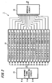
- FIG 1 illustrates a configuration of an image-pickup apparatus having an auto-focus mechanism according to one embodiment of the invention, such as a camcorder.
- the camcorder shown in FIG 1 is one model capable of switching focus operation between manual and auto-focus operation utilizing an AF image processing mechanism.
- a lens block of the camcorder includes a lens group having an image-pickup lens 1c and a focus lens 1; a position detector 1a; a lens mechanism 1b; a lens driver 2; a focus ring 1d; and an encoder 1e.
- a camera block includes an image-pickup device 3, an image-pickup device driver 4, an image signal generator 5, an image signal processor 6, an evaluation value calculator 7, a luminance addition value calculator 8, a control unit 9, a memory 10, and a switch 13.
- the lens block of the camcorder includes a lens group having an image-pickup lens 1c and a focus lens 1 configured to focus a subject image incident on the image-pickup lens 1c of an image-pickup surface of the image pickup device, a position detector configured to detect positions of each lens, a lens driving mechanism for driving each lens, and a lens driver configured to control movements of the lens driving mechanism.
- Lenses other than the focus lens 1 and the image-pickup lens 1c such as a wobbling lens which is utilized for determining directions of a focus position are omitted from the lens block shown in FIG 1 .
- the focus lens 1 includes the position detector 1a configured to detect positions of the focus lens 1, namely a focus position, the lens driving mechanism 1b configured to move the positions of the focus lens in the direction of an optical axis, and the lens driver 2 configured to control movements of the lens driving mechanism 1b.
- the wobbling lens (not shown) includes a wobbling lens driving mechanism for moving the position detector 1a and the position of the lens in the direction of an optical axis in order to perform appropriate wobbling.
- the lens block further includes an iris or diaphragm (not shown) for controlling the amount of incident light.
- the iris includes an iris position detector configure to detect an aperture of the iris, and an iris driving mechanism for opening and closing the iris. Notice that the focus lens can also be utilized as the wobbling lens in this embodiment.
- a focus ring 1d is utilized for manually adjusting a focus of the camcorder on the subject.
- the focus on the subject can manually be adjusted by turning the focus ring 1d.
- Degrees of a turn of the focus ring 1d can be detected by an encoder 1e, and the detected degrees are converted into a pulse signal by an encoder counter (not shown). The converted pulse signal is then output to the control unit 9.
- the lens driver 2 is supplied with various detected signals from the position detector 1a, such as a signal indicating a focus position, a signal indicating an amount of wobbling, and a signal indicating the aperture of the iris.
- the lens driver 2 including a lens CPU and a lens drive circuit is configured to move a focus (focal point) of the focus lens 1 according to instructions transmitted from the control unit 9.
- the lens driver 2 is connected with a user interface (not shown) for setting an auto-focus mode or initiating the auto-focus operation, so that the lens driver 2 is supplied with operation signals according to operation of the user interface.
- the lens driver 2 includes a storage (not shown) utilizing a ROM or EEPROM, on which information is stored, such as focal length data of the focus lens 1 and the wobbling lens, aperture ratio data, the name of manufacturer, and the serial number of the manufacturer.
- the lens driver 2 generates a lens driving signal based on the stored information, detected signals, and the later-described focus control signal or wobbling control signal supplied from the control unit 9.
- the lens driver 2 also supplies the generated driving signal to the lens driving mechanism 1b, so that the focus lens 1 is moved to a position where a sired focus on the subject image is obtained.
- the lens driver 2 supplies the generated lens driving signal to the wobbling lens driving mechanism to wobble the wobbling lens so that the focus lens 1 will detect a direction of an in-focus position.
- the lens driver 2 further generates an iris driving signal to control the aperture of the iris.
- the subject image is formed on the image-pickup device 3 via the focus lens 1, is then photo-electrically converted into an electric signal by the image-pickup device 3.
- the resulting signal is then output to the image generator 5 located subsequent to the image-pickup device3.
- the image-pickup device 3 may include a CCD (Charge Coupled Devices), CMOS (Complementary Metal Oxide Semiconductor), and the like.
- the image-pickup device driver 4 is one example of the image-pickup device drive circuit that supplies a driving signal to the image-pickup device 3 for photo-electronically converting the subject image formed on the image-pickup device 3 into an electric signal.
- the driving signal is supplied to the image-pickup device 3 based on a vertical synchronization signal VD, a horizontal synchronization signal HD, and a clock signal CLK generated from a clock signal generator (not shown), which are all used for a standard operation for components of the camcorder.
- an electric signal output from the image-pickup device 3 is subject to appropriate signal processing to generate an image signal complied with a predetermined standard.
- the image signal is transmitted to a circuit group (image signal processor 6) subsequent to the camcorder while being input to the evaluation value calculator 7.
- the evaluation value calculator 7 filters a high frequency component of an image signal in a specific region provided within an image-pickup frame, and calculates an evaluation value relative to the image contrast. While imaging a typical subject, an evaluation value increases as the subject image approaches in-focus state, and the evaluation value reaches the relative maximum when the subject image is in-focus. The aforementioned evaluation value is updated once for one field of an image signal. Auto-focus operation using evaluation values is well-known technology in the art, one example of which is described in detail in Japanese Patent Application Publication No. 10-213736 previously disclosed by the applicant of the invention.
- the camera block includes a color separating prism (not shown).
- the color separating prism separates light incident from the lens block into the three primary colors R, G, and B, and supplies the R component light to R component image-pickup device, the G component light to G component light to G component image-pickup device, and the B component light to B component image-pickup device, respectively.
- the three R, G, and B component image-pickup devices are represented as an image-pickup device 3.
- the subject image having the tree colors formed on the image-pickup device 3 is subject to predetermined processing before the subject image is photo-electrically converted into a signal by the image-pickup device 3 and output to the image signal generator 5.
- the image signal generator 5, for example, includes a preamplifier (not shown) and an A/D (Analog/Digital) converter. The level of the electric signals input to the image signal generator 5 is amplified by the preamplifier, and correlated double sampling is performed on the signals to eliminate a reset noise, and the A/D converter converts an analog signal into a digital image signal. Further, the image signal generator 5 is configured to perform gain control, black level stabilizer, or dynamic range control, and the like of the supplied image signals for each color, and supply the thus obtained image signals to the image processor 6, the evaluation value calculator 7, and the luminance addition value calculator 8.
- the image signal generator 6 performs various signal processing on the image signals supplied from the image signal generator 5, and generates output image signals.
- the various signal processing includes knee correction to compress image signals having a level equal to or higher than a certain level, gamma correction to correct the level of the image signal based on a configured gamma curve, and white clip processing or black clip processing to control the level of the image signal to fall within a predetermined range.
- the image signal generator 6 also performs edge enhancement or linear matrix processing, and encodes processing for generating the output image signal with a desired format.
- the evaluation value calculator 7 filters the high frequency component using image signals in a specific region provided within the image pickup frame to calculate an evaluation value ID corresponding to the image contrast and supply the calculated evaluation value ID to the control unit 9.
- those processing performed at the image signal generator 5 having such as a preamplifier and an analog-digital (A-D) converter, the image signal processor 6, the evaluation value calculator 7, and the like employ the vertical direction synchronization signal VD, the horizontal direction synchronization signal HD, and the clock signal CLK supplied from units located prior to the image signal generator 5, the image signal processor 6, the evaluation value calculator 7 in order to perform the respective processing.
- these signals may be obtained from the clock signal generator.
- FIG 2 illustrates a configuration of the evaluation value calculator 7.
- the evaluation value calculator 7 includes a luminance signal generation circuit 21 to generate a luminance signal DY based on an image signal for each color, the evaluation value generation circuit 22 to generate 15 evaluation values ID0 to ID14 as described below, and an interface circuit 23.
- the interface circuit 23 is configured to communicate with the control unit 9 and supply the generated evaluation values according to requests from the control unit 9.
- the luminance signal DY is generated in this manner, because it is sufficient to simply detect changes in the level of contrast and determine whether contrast is high or low in order to determine whether a subject image is in-focus or out of focus. Notice that the aforementioned operational expression of the luminance signal DY is not limited thereto, and various other expressions can also be applied.
- the evaluation value generator 22 generates 15 evaluation values ID0 to ID14.
- the evaluation values ID0 to ID14 are obtained by summing the frequency components of image signals in a specific region (hereinafter called “evaluation frame") provided within the image pickup frame, and provide values corresponding to the blurring of the image.
- evaluation values are essentially the results of summing the frequency components of image signals in a specific region provided in a image pickup frame (hereafter called the "evaluation frame”), and provide values corresponding to the blurring of the image.
- the data used for calculating evaluation values include two types, namely, IIR-type and Y-type data.
- IIR-type data includes high-frequency components filtered from the luminance signal DY by a HPF (high-pass filter); whereas Y-type data includes original luminance signal DY.
- HPF high-pass filter
- the HPF used above is an IIR-type (infinite impulse response type) HPF.
- the evaluation values are divided into IIR0, IIR1, IIR3, and IIR4, based on the types of HPF. This implies that each type of HPF has a different cutoff frequency. Accordingly, the evaluation values can be obtained with HPFs having different cutoff frequencies. For example, the evaluation value obtained using a HPF having a high cutoff frequency can exhibit a significant change in the vicinity of the focus position as compared with the case of using a HPF with a low cutoff frequency.
- the evaluation value generator 22 includes HPFs having different cutoff frequencies in order to select the optimal evaluation value based on the current focus state in auto-focus operation.
- An image pickup frame 40 can, for example, be divided into 15 areas (a0 to a4, b0 to b4, c0 to c4) having three rows and five columns as shown in FIG 3 .
- the size of the evaluation frame or the size of the image region, which is used for generating evaluation values, can be determined based on the size of the image pickup frame 40 and the number of divisions.
- the above embodiment illustrates 15 divisions as one example; however, the number of divisions of the image pickup frame 40 is not limited thereto, and any number of divisions can also be employed.
- the image pickup frame 40 is divided into a plurality of frames to generate the evaluation values corresponding to the frame sizes.
- an appropriate evaluation value can be obtained by assigning one of the evaluation values ID0 to ID14, regardless of the position of the target subject in the image pickup frame.
- evaluation value calculation methods including the HPeak, HIntg, VIntg, and Satul.
- the HPeak system implies calculating horizontal evaluation values by the peak system; the HIntg system includes calculating horizontal evaluation values by the whole integration system; the VIntg system involves calculating vertical-direction evaluation values by the integration system, and the Satul system includes calculating the number of data indicating saturated luminance.
- the evaluation calculation method by the HPeak system (horizontal evaluation value calculation) will be described as one example utilized in an embodiment; however, the evaluation calculation method is not limited to this example.
- the HPeak method involves one of the evaluation value calculation methods with which the high frequency component is filtered by a HPF from the horizontal image signal.
- FIG.4 shows a configuration of a horizontal-direction evaluation value calculation filter used for the HPeak method.
- the horizontal-direction evaluation value calculation filter includes a HPF 31 that filters only high-frequency components from the luminance signals DY of the luminance signal generation circuit 21; an absolute value processing circuit 32 that selects the absolute values of the high-frequency components; a multiplication circuit 33 that multiplies the absolute values of the high-frequency components by the horizontal-direction frame control signal WH; a line peak hold circuit 34 that holds one peak value per line; and a vertical-direction integration circuit 35 that integrates the peak values for all the lines in the evaluation frame in the vertical direction.
- the high-frequency components of the luminance signals DY are filtered by the HPF 31, and then converted into absolute values by the absolute value processing circuit 32. Subsequently, the horizontal-direction frame control signal WH is multiplied by the multiplication circuit 33 to obtain absolute values of high-frequency components within the evaluation frame. That is, if frame control signals WH the multiplication value of which is "0" outside the evaluation frame are supplied to the multiplication circuit 33, then only the absolute values of horizontal-direction high-frequency components within the evaluation frame are supplied to the line peak hold circuit 34.
- the frame control signals WH in the vertical direction form a square wave; however, the frame control signals WH in the horizontal direction do not merely include characteristics of a mere square wave but include characteristics of a triangular wave, so that the multiplied value of the frame control signals WH is reduced in the periphery of the frame (both ends).
- the line peak hold circuit 34 holds the peak values for each line.
- the vertical-direction integration circuit 35 adds peak values held for each line within the evaluation frame in the vertical direction, based on vertical-direction frame control signals WV, thereby obtaining the evaluation value. This method is called the HPeak method, because horizontal-direction (H) peaks are held temporarily.
- the evaluation value calculator 8 is a circuit configured to integrate the luminance of the image signals in the specific region obtained by the image pickup device and generate the luminance addition value.
- the evaluation value calculator 8 adds the luminance signals in a specific region obtained from image signals for each color input from the image signal generator 5, and the added result is output to the control unit 9 as the luminance addition values.
- the control unit 9 for example, includes a CPU (Central Processing Unit), RAM (Random Access Memory), and ROM (Read Only Memory), and retrieves computer programs stored in the ROM onto the RAM to run the programs, and hence a predetermined control and processing such as auto-focus operation are performed.
- the control unit 9 obtains evaluation values calculated by an evaluation value calculator 7 once for each field, and searches the peak of the evaluation values.
- the auto-focus operation is carried out when the control unit 9 detects that the focus lens has stopped or the manual focus operation has stopped. Alternatively, the auto-focus operation is performed using an instruction as a trigger from a one-shot switch 13 that directs activation of the auto-focus operation.
- the control unit 9 and the lens driver 2 of the lens block are configured such that the control unit 9 and the lens driver 2 may communicate with each other using predetermined formats and protocols, and collaborate to control the auto-focus operation.
- the lens driver 2 supplies various information including a focus position or a value indicating the size of an iris to the control unit 9 upon request.
- the lens driver 2 generates a lens drive signal based on a focus control signal or wobbling control signal supplied from the control unit 9 to perform drive processing of the focus lens 1 and wobbling lens.
- the control unit 9 generates the focus control signal to drive control the focus lens 1 or the wobbling control signal to drive control the wobbling lens, and supplies the respective signals to the lens driver 2, based on the evaluation value ID calculated by the evaluation calculator and the various information retrieved from the driver 2.
- Each of the lens driver 2 and the control unit 9 incorporates a microcomputer and a memory to perform the auto-focus operation by retrieving to run a program stored in the non-volatile memory.
- a memory 10 is a storage unit into which data are written and from which data are read out by the control unit 9.
- the storage unit is configured to store information such as the focus position of the focus lens 1 and the evaluation value calculated by the evaluation value calculator 7.
- the memory 10 includes a non-volatile memory such as semiconductor memories.
- a liquid crystal monitor driver 14 is configured to generate an image signal output from a signal processor 6 and drive signals for displaying characters, icons, or the like on a monitor 15 directed by the control unit 9.
- the drive signal is supplied to a viewfinder 15 based on respective synchronization signals and the clock signal included in the image signals.
- the viewfinder 15 is one example of display units, for which a liquid crystal display device (LCD) may be used.
- the viewfinder 15 receives drive signals supplied from the monitor driver 14 to display images according to supplied signals.
- the viewfinder 15 may be a monitor provided with a camcorder.
- a user manually adjusts a focus on a subject; the auto-focus mechanism then automatically detects the manually focused subject and image processing the subject image to adjust the final precision of the focus.
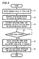
- the algorithm to cause the auto-focus mechanism to function roughly has the following two processes.
- the control unit 9 detects a manually focusing operation status from an encoder value of the focus ring 1d detected by an encoder 1e (step S1).
- the control unit 9 stores the encoder value in the memory 10, and then acquires a fluctuation history data (step S2).
- the control unit 9 determines whether a user has started or stopped the focus ring operation based on the fluctuation history data.
- the control unit 9 is continuously monitoring which area (detecting frame) of the image is most approaching the in-focus position, based on the focal change of the image picked up by the image pickup device 3 while the focus ring 1d is being operated (steps S3, S4).
- the control unit 9 determines the area (defecting frame) that is subjected to the final precision adjustment of the focal point just after having detected the end of the focus ring operation (step S5). In this embodiment, the control unit 9 selects the detecting frame based on the history of the evaluation value fluctuations obtained just before the user has stopped the focus ring. The control unit 9 then carries out auto-focus processing using image processing, based on the evaluation value obtained in the selected area (detecting frame) (step S6). The level and fluctuations of the evaluation value are controlled so that the distance between the current focus position and the focus position obtained on activating auto-focus processing is not largely changed. Described is the method for controlling the level or fluctuations of the evaluation values.
- the detecting frame of the embodiment differs from those set in the center of the screen that are utilized for an ordinary auto-focus or one-shot auto-focus processing.
- the detecting frame of the embodiment is set after dividing a screen into a plurality of frames.
- the control unit 10 monitors histories of the evaluation values of the respective detecting frames while the user manually operates the focus ring, and selects a detecting frame with a subject image in which significant fluctuations of the evaluation values are detected. Then, autofocus processing utilizing image processing algorithm can be performed on the detecting frame selected.
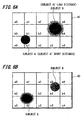
- FIGS. 6A, 6B are diagrams each illustrating one example of how a picked up image is divided by frames.
- a subject in-focus is illustrated with a small representation
- a subject out-of-focus is illustrated with a large representation.
- FIG. 7 is a diagram illustrating fluctuations of an evaluation values with time while a focus ring is operated.
- the image obtained from the image pickup device 3 is divided into 15 areas, for respective of which evaluation values are computed.
- An image pickup frame 40 can, for example, be divided into 15 areas (a0 to a4, b0 to b4, c0 to c4) having three rows and five columns as shown in FIGS. 6A, 6B . It is preferable that the number of frames to be divided is optimally determined according to the capacity of the evaluation value calculator 7. Note that the image pickup frame is divided for setting areas (evaluation frames) so that the evaluation values are computed in each of the divided areas. Thus, the user may not need paying any attention to the divided areas (evaluation frames) while viewing the viewfinder.
- the evaluation values in the divided areas (detecting frames) can simultaneously be computed by the evaluation value calculator 7.
- the evaluation values in the divided areas (detecting frames) can be computed in sequence according to a predetermined rule by an evaluation value calculator 7.
- the evaluation values in the areas from a0 to c4 can be computed in sequence per one field. In this case, the number of areas for computing evaluation values that can be afforded by the evaluation value calculator 7 alone can exceed the capacity thereof.
- the evaluation value calculator 7 periodically obtains high frequency components (evaluation values) of image signals in the divided areas.
- the evaluation value increases when the subject image approaches an in-focus state. More details can be described with reference to a subject A positioned at a short distance and a subject B at a long distance in FIGS 6A, 6B .
- the evaluation value in the area c1 containing the subject image A with in-focus state is high, whereas the evaluation value in the area b3 containing the subject image B with out-of-focus state is low (see FIG. 7 ).
- the user moves the focus ring 1d close to the position where the user desires the subject B to be in-focus, and then stops operating the focus ring 1d (t2).
- the evaluation value output from the evaluation value calculator 7 fluctuates as the user moves the focus ring 1d, and the area where the evaluation value significantly increases just before the focus ring 1d has stopped can be estimated as the area where the user desires the subject to be in-focus.
- the memory 10 constantly stores the images obtained at several fields back to the past, and hence the evaluation value just before the focus ring has stopped can be obtained by computing these images.
- the first method is evaluating the histories based on increments in the evaluation values obtained just before the focus ring has stopped; and the second method is based on whether or not the relative maximum of the evaluation values is detected in the duration between the time just before the manual focus ring operation has been stopped and the time the focus operation has stopped.
- the control unit 9 determines the area having a history where the significant increments of the evaluation values are detected just before the focus ring has stopped as the area where the user desires the subject to be in-focus.
- the first method is especially effective when the evaluation values just before the focus ring has stopped continuously increase. For example, suppose that the focus ring operation has stopped at the time t3 in FIG 7 .
- the evaluation value obtained when the focus ring operation has stopped at the time t3 is B3
- the evaluation value B2 is larger than B3 (i.e., B2 > B3)
- the increments k3 obtained when the focus ring operation has stopped at the time t3 is lower than the increments k2 obtained when the focus ring operation has stopped at the time t2. Therefore, the control unit 9 may not determine the area having the history where the significant increments of the evaluation values are detected just before the focus ring has stopped as the area where the user desires the subject to be in-focus.
- the histories of the evaluation values are evaluated based on whether or not the relative maximum of the evaluation values is detected in the duration between the time just before the manual focus ring operation has been stopped and the time the focus operation has stopped.
- the control unit 9 detects the relative maximum P before the focus ring operation has been stopped, and determines the area having a history where the relative maximum of the evaluation values has been detected as the area where the user desires the subject to be in-focus. In this manner, even though the user wrongly operates the focus ring to miss the in-focus position (i.e., the evaluation value P), the control unit 9 can still determines the area where the user desires the subject to be in-focus.
- the ratio (relative maximum/evaluation value at the start of focus operation) of the evaluation value at the start of the auto-focus operation to the relative maximum of the evaluation values is equal to or less than a predetermined value such as noise, the method where the relative maximum is detected can be invalidated. As a result, wrong detection of the area where the user desires the subject to be in-focus due to noise can be prevented.
- step S6 how auto-focus processing is performed on the area that the control unit has estimated as the area where the user desires the subject to be in-focus at step S6 is described in detail.
- auto-focus processing is once performed on the area selected, as an auto-focus processing area, based on the fluctuation history of the evaluation value obtained just before the focus ring has stopped.
- the auto-focus processing herein implies image processing system utilizing evaluation values as auto-focus algorithm in the related art.
- the focus of the subject image in the selected area is already adjusted close to the in-focus position. Therefore, it may not be necessary to move the focus of the subject image from the position at the activation of the auto-focus processing.
- the following processing is performed so as to prevent the user from obtaining undesired focus position.
- the range of the focus adjusting area is limited based on the focus position obtained at the activation of auto-focus processing.
- the focus adjusting area can be limited based on the range of the focus adjusting area, the multiple of focal depth, and the range of the focus adjusting time. Thus, undesired focus position that differs from the focus position obtained by the user's manual adjustment can be prevented.
- the auto-focus processing terminates at that point.
- the optimal focus position can be obtained accordingly.
- the focus position moves back to the position at the activation of the auto-focus processing, and the auto-focus processing terminates thereafter.
- the focus position will eventually be the manually adjusted position; however, the user can at least maintain the desired focus position of the subject image.
- the user can manually adjust the focus on a subject image as she or he desires, and once the user approximately adjusts the focus on the desired subject, the auto-focus processing is performed on the subject image to adjust the focus more precisely.
Description
- The invention relates to an auto-focus apparatus, an image pickup apparatus, and an auto-focus method,
- A typical image pickup apparatus in the related art, such as camcorders or digital still cameras, includes an auto-focus control unit or AF (automatically adjusting focus) function for automatically adjusting the focus on a subject. A user can either select imaging the subject with a manual focus or an autofocus functions provided for the image pickup apparatus.
-
Japanese Patent Application Publication No. 2003-241077 - For example, when a user sets the camcorder to a manual-focus operation mode to adjust a focus on a subject manually, the user usually adjust the focus on the subject while viewing the subject image via viewfinder. Existing camcorder models typically have small viewfinder displays each having approximately 5.08 cm (two-inches) at the largest. It is generally difficult to adjust a focus on the subject using a viewfinder having a small display, and the difficulty will become more obvious when the subject image, the focus of which has once been adjusted by observing the viewfinder having a small display, is displayed by a high definition display. In other words, the focus on the subject image appears to have been adjusted on the small screen display of an electric viewfinder; however, in reality, it becomes obvious that the focus has not been adjusted when the subject image is displayed on the high-definition display having approximately 10.16 cm (four-inches).
- In contrast, when the user sets the camcorder an auto-focus operation mode, the focus is automatically adjusted on the subject displayed on a screen of the viewfinder without fail; however, a detecting area is generally set to the center of the screen. In this case, the detecting area does not necessarily match with the subject on the screen on which the user tries to adjust a focus.
-
US 2007/071432 A discloses a prior art device having an auto-focus system. - Embodiments of the invention have attempted to provide an auto-focus apparatus, image pickup apparatus, and auto-focus method capable of obtaining an accurate focus adjustment using both manual-focus and auto-focus processing.
- According to embodiments of the invention, attempts have been made to provide an auto-focus apparatus utilized for an image pickup apparatus having a focus ring. The auto-focus apparatus is defined by
independent claim 1. - According to an embodiment of the invention, a user manually first adjusts a focus on a subject, the auto-focus mechanism automatically detects the subject and image processed so as to adjust final precision of the focus on the subject.
- According to an embodiment of the invention, the user can manually first adjust a focus on a subject, and optionally activate an auto-focus function to adjust the focus on appropriate areas of the subject image.
- Preferably, the present invention relates to an image pickup apparatus as defined in
independent claim 9, and auto-focus method as defined inindependent claim 10 capable of automatically adjusting a focus on a subject with accuracy (hereinafter called "in-focus") based on evaluation values obtained by image data processing. - Various respective aspects and features of the invention are defined in the appended claims.
- Embodiments of the invention will now be described with reference to the accompanying drawings, throughout which like parts are referred to by like references, and in which:
-
FIG 1 is a block diagram illustrating a configuration of a camcorder according to one embodiment of the invention. -
FIG 2 is a diagram illustrating a configuration of an evaluation value calculator. -
FIG 3 is a diagram illustrating one example of how an image picked up is divided by frames. -
FIG 4 is a diagram illustrating a configuration of a horizontal direction evaluation value calculating filter. -
FIG 5 is a flowchart illustrating focus processing according to one embodiment of the invention. -
FIGS. 6A, 6B are diagrams each illustrating one example of how an image picked up is divided by frames. -
FIG 7 is a diagram illustrating one example of fluctuations of an evaluation value with time while a focus ring is operated. -
FIG 1 illustrates a configuration of an image-pickup apparatus having an auto-focus mechanism according to one embodiment of the invention, such as a camcorder. The camcorder shown inFIG 1 is one model capable of switching focus operation between manual and auto-focus operation utilizing an AF image processing mechanism. A lens block of the camcorder includes a lens group having an image-pickup lens 1c and afocus lens 1; aposition detector 1a; alens mechanism 1b; alens driver 2; afocus ring 1d; and an encoder 1e. A camera block includes an image-pickup device 3, an image-pickup device driver 4, animage signal generator 5, animage signal processor 6, anevaluation value calculator 7, a luminanceaddition value calculator 8, acontrol unit 9, amemory 10, and aswitch 13. - The lens block of the camcorder includes a lens group having an image-
pickup lens 1c and afocus lens 1 configured to focus a subject image incident on the image-pickup lens 1c of an image-pickup surface of the image pickup device, a position detector configured to detect positions of each lens, a lens driving mechanism for driving each lens, and a lens driver configured to control movements of the lens driving mechanism. Lenses other than thefocus lens 1 and the image-pickup lens 1c such as a wobbling lens which is utilized for determining directions of a focus position are omitted from the lens block shown inFIG 1 . - The
focus lens 1 includes theposition detector 1a configured to detect positions of thefocus lens 1, namely a focus position, thelens driving mechanism 1b configured to move the positions of the focus lens in the direction of an optical axis, and thelens driver 2 configured to control movements of thelens driving mechanism 1b. Likewise, the wobbling lens (not shown) includes a wobbling lens driving mechanism for moving theposition detector 1a and the position of the lens in the direction of an optical axis in order to perform appropriate wobbling. The lens block further includes an iris or diaphragm (not shown) for controlling the amount of incident light. The iris includes an iris position detector configure to detect an aperture of the iris, and an iris driving mechanism for opening and closing the iris. Notice that the focus lens can also be utilized as the wobbling lens in this embodiment. - A
focus ring 1d is utilized for manually adjusting a focus of the camcorder on the subject. The focus on the subject can manually be adjusted by turning thefocus ring 1d. Degrees of a turn of thefocus ring 1d can be detected by an encoder 1e, and the detected degrees are converted into a pulse signal by an encoder counter (not shown). The converted pulse signal is then output to thecontrol unit 9. - The
lens driver 2 is supplied with various detected signals from theposition detector 1a, such as a signal indicating a focus position, a signal indicating an amount of wobbling, and a signal indicating the aperture of the iris. Thelens driver 2 including a lens CPU and a lens drive circuit is configured to move a focus (focal point) of thefocus lens 1 according to instructions transmitted from thecontrol unit 9. Thelens driver 2 is connected with a user interface (not shown) for setting an auto-focus mode or initiating the auto-focus operation, so that thelens driver 2 is supplied with operation signals according to operation of the user interface. Thelens driver 2 includes a storage (not shown) utilizing a ROM or EEPROM, on which information is stored, such as focal length data of thefocus lens 1 and the wobbling lens, aperture ratio data, the name of manufacturer, and the serial number of the manufacturer. - The
lens driver 2 generates a lens driving signal based on the stored information, detected signals, and the later-described focus control signal or wobbling control signal supplied from thecontrol unit 9. Thelens driver 2 also supplies the generated driving signal to thelens driving mechanism 1b, so that thefocus lens 1 is moved to a position where a sired focus on the subject image is obtained. Thelens driver 2 supplies the generated lens driving signal to the wobbling lens driving mechanism to wobble the wobbling lens so that thefocus lens 1 will detect a direction of an in-focus position. Thelens driver 2 further generates an iris driving signal to control the aperture of the iris. - In the camcorder shown in
FIG 1 , the subject image is formed on the image-pickup device 3 via thefocus lens 1, is then photo-electrically converted into an electric signal by the image-pickup device 3. The resulting signal is then output to theimage generator 5 located subsequent to the image-pickup device3. The image-pickup device 3 may include a CCD (Charge Coupled Devices), CMOS (Complementary Metal Oxide Semiconductor), and the like. The image-pickup device driver 4 is one example of the image-pickup device drive circuit that supplies a driving signal to the image-pickup device 3 for photo-electronically converting the subject image formed on the image-pickup device 3 into an electric signal. The driving signal is supplied to the image-pickup device 3 based on a vertical synchronization signal VD, a horizontal synchronization signal HD, and a clock signal CLK generated from a clock signal generator (not shown), which are all used for a standard operation for components of the camcorder. - In the
image signal generator 5, an electric signal output from the image-pickup device 3 is subject to appropriate signal processing to generate an image signal complied with a predetermined standard. The image signal is transmitted to a circuit group (image signal processor 6) subsequent to the camcorder while being input to theevaluation value calculator 7. Theevaluation value calculator 7 filters a high frequency component of an image signal in a specific region provided within an image-pickup frame, and calculates an evaluation value relative to the image contrast. While imaging a typical subject, an evaluation value increases as the subject image approaches in-focus state, and the evaluation value reaches the relative maximum when the subject image is in-focus. The aforementioned evaluation value is updated once for one field of an image signal. Auto-focus operation using evaluation values is well-known technology in the art, one example of which is described in detail in Japanese Patent Application Publication No.10-213736 - The aforementioned processing is performed for each of three primary colors R (Red), G (Green), and B (Blue). For example, the camera block includes a color separating prism (not shown). The color separating prism separates light incident from the lens block into the three primary colors R, G, and B, and supplies the R component light to R component image-pickup device, the G component light to G component light to G component image-pickup device, and the B component light to B component image-pickup device, respectively. In
FIG 1 , the three R, G, and B component image-pickup devices are represented as an image-pickup device 3. - The subject image having the tree colors formed on the image-
pickup device 3 is subject to predetermined processing before the subject image is photo-electrically converted into a signal by the image-pickup device 3 and output to theimage signal generator 5. Theimage signal generator 5, for example, includes a preamplifier (not shown) and an A/D (Analog/Digital) converter. The level of the electric signals input to theimage signal generator 5 is amplified by the preamplifier, and correlated double sampling is performed on the signals to eliminate a reset noise, and the A/D converter converts an analog signal into a digital image signal. Further, theimage signal generator 5 is configured to perform gain control, black level stabilizer, or dynamic range control, and the like of the supplied image signals for each color, and supply the thus obtained image signals to theimage processor 6, theevaluation value calculator 7, and the luminanceaddition value calculator 8. - The
image signal generator 6 performs various signal processing on the image signals supplied from theimage signal generator 5, and generates output image signals. The various signal processing includes knee correction to compress image signals having a level equal to or higher than a certain level, gamma correction to correct the level of the image signal based on a configured gamma curve, and white clip processing or black clip processing to control the level of the image signal to fall within a predetermined range. Theimage signal generator 6 also performs edge enhancement or linear matrix processing, and encodes processing for generating the output image signal with a desired format. - The
evaluation value calculator 7 filters the high frequency component using image signals in a specific region provided within the image pickup frame to calculate an evaluation value ID corresponding to the image contrast and supply the calculated evaluation value ID to thecontrol unit 9. - Notice that those processing performed at the
image signal generator 5 having such as a preamplifier and an analog-digital (A-D) converter, theimage signal processor 6, theevaluation value calculator 7, and the like employ the vertical direction synchronization signal VD, the horizontal direction synchronization signal HD, and the clock signal CLK supplied from units located prior to theimage signal generator 5, theimage signal processor 6, theevaluation value calculator 7 in order to perform the respective processing. Alternatively, these signals may be obtained from the clock signal generator. - The
evaluation value calculator 7 is described more in detail below.FIG 2 illustrates a configuration of theevaluation value calculator 7. Theevaluation value calculator 7 includes a luminancesignal generation circuit 21 to generate a luminance signal DY based on an image signal for each color, the evaluationvalue generation circuit 22 to generate 15 evaluation values ID0 to ID14 as described below, and aninterface circuit 23. Theinterface circuit 23 is configured to communicate with thecontrol unit 9 and supply the generated evaluation values according to requests from thecontrol unit 9. - The
image signal generator 21 performs the following operation: DY = 0.30R + 0.59G + 0.11 G using the image signals R, G, B supplied from theimage signal generator 5 and generate a luminance signal DY. The luminance signal DY is generated in this manner, because it is sufficient to simply detect changes in the level of contrast and determine whether contrast is high or low in order to determine whether a subject image is in-focus or out of focus. Notice that the aforementioned operational expression of the luminance signal DY is not limited thereto, and various other expressions can also be applied. - The
evaluation value generator 22 generates 15 evaluation values ID0 to ID14. The evaluation values ID0 to ID14 are obtained by summing the frequency components of image signals in a specific region (hereinafter called "evaluation frame") provided within the image pickup frame, and provide values corresponding to the blurring of the image. These evaluation values are essentially the results of summing the frequency components of image signals in a specific region provided in a image pickup frame (hereafter called the "evaluation frame"), and provide values corresponding to the blurring of the image. - The data used for calculating evaluation values include two types, namely, IIR-type and Y-type data. IIR-type data includes high-frequency components filtered from the luminance signal DY by a HPF (high-pass filter); whereas Y-type data includes original luminance signal DY.
- The HPF used above is an IIR-type (infinite impulse response type) HPF. The evaluation values are divided into IIR0, IIR1, IIR3, and IIR4, based on the types of HPF. This implies that each type of HPF has a different cutoff frequency. Accordingly, the evaluation values can be obtained with HPFs having different cutoff frequencies. For example, the evaluation value obtained using a HPF having a high cutoff frequency can exhibit a significant change in the vicinity of the focus position as compared with the case of using a HPF with a low cutoff frequency. In addition, when the pickup image is largely out of focus, the evaluation value obtained using a HPF having a low cutoff frequency can exhibit a significant change as compared with the case of using a HPF with a high cutoff frequency. Thus, the
evaluation value generator 22 includes HPFs having different cutoff frequencies in order to select the optimal evaluation value based on the current focus state in auto-focus operation. - An
image pickup frame 40 can, for example, be divided into 15 areas (a0 to a4, b0 to b4, c0 to c4) having three rows and five columns as shown inFIG 3 . The size of the evaluation frame or the size of the image region, which is used for generating evaluation values, can be determined based on the size of theimage pickup frame 40 and the number of divisions. The above embodiment illustrates 15 divisions as one example; however, the number of divisions of theimage pickup frame 40 is not limited thereto, and any number of divisions can also be employed. - Thus, the
image pickup frame 40 is divided into a plurality of frames to generate the evaluation values corresponding to the frame sizes. Hence, an appropriate evaluation value can be obtained by assigning one of the evaluation values ID0 to ID14, regardless of the position of the target subject in the image pickup frame. - As disclosed in Patent Application Publication No.
10-213736 - The HPeak method involves one of the evaluation value calculation methods with which the high frequency component is filtered by a HPF from the horizontal image signal.
FIG.4 shows a configuration of a horizontal-direction evaluation value calculation filter used for the HPeak method. The horizontal-direction evaluation value calculation filter includes aHPF 31 that filters only high-frequency components from the luminance signals DY of the luminancesignal generation circuit 21; an absolutevalue processing circuit 32 that selects the absolute values of the high-frequency components; amultiplication circuit 33 that multiplies the absolute values of the high-frequency components by the horizontal-direction frame control signal WH; a linepeak hold circuit 34 that holds one peak value per line; and a vertical-direction integration circuit 35 that integrates the peak values for all the lines in the evaluation frame in the vertical direction. - The high-frequency components of the luminance signals DY are filtered by the
HPF 31, and then converted into absolute values by the absolutevalue processing circuit 32. Subsequently, the horizontal-direction frame control signal WH is multiplied by themultiplication circuit 33 to obtain absolute values of high-frequency components within the evaluation frame. That is, if frame control signals WH the multiplication value of which is "0" outside the evaluation frame are supplied to themultiplication circuit 33, then only the absolute values of horizontal-direction high-frequency components within the evaluation frame are supplied to the linepeak hold circuit 34. Here, the frame control signals WH in the vertical direction form a square wave; however, the frame control signals WH in the horizontal direction do not merely include characteristics of a mere square wave but include characteristics of a triangular wave, so that the multiplied value of the frame control signals WH is reduced in the periphery of the frame (both ends). As a result, as the subject image within the frame approaches being in-focus, it is possible to reduce effects caused by the subject image interfering the external edges around the periphery of the frame (high luminance edges in the evaluation frame, including noise, drastic change, or the like of the evaluation values) or variation in the evaluation values caused by the movement of the subject can be decreased. The linepeak hold circuit 34 holds the peak values for each line. The vertical-direction integration circuit 35 adds peak values held for each line within the evaluation frame in the vertical direction, based on vertical-direction frame control signals WV, thereby obtaining the evaluation value. This method is called the HPeak method, because horizontal-direction (H) peaks are held temporarily. - The configuration of the camcorder is described by referring back to
FIG 1 . Theevaluation value calculator 8 is a circuit configured to integrate the luminance of the image signals in the specific region obtained by the image pickup device and generate the luminance addition value. Theevaluation value calculator 8 adds the luminance signals in a specific region obtained from image signals for each color input from theimage signal generator 5, and the added result is output to thecontrol unit 9 as the luminance addition values. - The
control unit 9, for example, includes a CPU (Central Processing Unit), RAM (Random Access Memory), and ROM (Read Only Memory), and retrieves computer programs stored in the ROM onto the RAM to run the programs, and hence a predetermined control and processing such as auto-focus operation are performed. Thecontrol unit 9 obtains evaluation values calculated by anevaluation value calculator 7 once for each field, and searches the peak of the evaluation values. The auto-focus operation is carried out when thecontrol unit 9 detects that the focus lens has stopped or the manual focus operation has stopped. Alternatively, the auto-focus operation is performed using an instruction as a trigger from a one-shot switch 13 that directs activation of the auto-focus operation. - The
control unit 9 and thelens driver 2 of the lens block are configured such that thecontrol unit 9 and thelens driver 2 may communicate with each other using predetermined formats and protocols, and collaborate to control the auto-focus operation. Thelens driver 2 supplies various information including a focus position or a value indicating the size of an iris to thecontrol unit 9 upon request. Thelens driver 2 generates a lens drive signal based on a focus control signal or wobbling control signal supplied from thecontrol unit 9 to perform drive processing of thefocus lens 1 and wobbling lens. Thecontrol unit 9 generates the focus control signal to drive control thefocus lens 1 or the wobbling control signal to drive control the wobbling lens, and supplies the respective signals to thelens driver 2, based on the evaluation value ID calculated by the evaluation calculator and the various information retrieved from thedriver 2. - Each of the
lens driver 2 and thecontrol unit 9 incorporates a microcomputer and a memory to perform the auto-focus operation by retrieving to run a program stored in the non-volatile memory. - A
memory 10 is a storage unit into which data are written and from which data are read out by thecontrol unit 9. The storage unit is configured to store information such as the focus position of thefocus lens 1 and the evaluation value calculated by theevaluation value calculator 7. Thememory 10 includes a non-volatile memory such as semiconductor memories. - A liquid
crystal monitor driver 14 is configured to generate an image signal output from asignal processor 6 and drive signals for displaying characters, icons, or the like on amonitor 15 directed by thecontrol unit 9. The drive signal is supplied to aviewfinder 15 based on respective synchronization signals and the clock signal included in the image signals. - The
viewfinder 15 is one example of display units, for which a liquid crystal display device (LCD) may be used. Theviewfinder 15 receives drive signals supplied from themonitor driver 14 to display images according to supplied signals. Theviewfinder 15 may be a monitor provided with a camcorder. - Next, focus adjustment processing performed in an camcorder will be described according to an embodiment of the invention.
Basically, a user manually adjusts a focus on a subject; the auto-focus mechanism then automatically detects the manually focused subject and image processing the subject image to adjust the final precision of the focus. The algorithm to cause the auto-focus mechanism to function roughly has the following two processes. -
- Compute the area to which the target subject displayed based on the focusing fluctuations of the subject image while the user is manually operating the
focus ring 1d. - The above two processes are described in detail with reference to a flowchart shown in
FIG 5 . First, thecontrol unit 9 detects a manually focusing operation status from an encoder value of thefocus ring 1d detected by an encoder 1e (step S1). Thecontrol unit 9 stores the encoder value in thememory 10, and then acquires a fluctuation history data (step S2). Thecontrol unit 9 determines whether a user has started or stopped the focus ring operation based on the fluctuation history data. Thecontrol unit 9 is continuously monitoring which area (detecting frame) of the image is most approaching the in-focus position, based on the focal change of the image picked up by theimage pickup device 3 while thefocus ring 1d is being operated (steps S3, S4). - The
control unit 9 determines the area (defecting frame) that is subjected to the final precision adjustment of the focal point just after having detected the end of the focus ring operation (step S5). In this embodiment, thecontrol unit 9 selects the detecting frame based on the history of the evaluation value fluctuations obtained just before the user has stopped the focus ring. Thecontrol unit 9 then carries out auto-focus processing using image processing, based on the evaluation value obtained in the selected area (detecting frame) (step S6). The level and fluctuations of the evaluation value are controlled so that the distance between the current focus position and the focus position obtained on activating auto-focus processing is not largely changed. Described is the method for controlling the level or fluctuations of the evaluation values. - The detecting frame of the embodiment differs from those set in the center of the screen that are utilized for an ordinary auto-focus or one-shot auto-focus processing. The detecting frame of the embodiment is set after dividing a screen into a plurality of frames. The
control unit 10 monitors histories of the evaluation values of the respective detecting frames while the user manually operates the focus ring, and selects a detecting frame with a subject image in which significant fluctuations of the evaluation values are detected. Then, autofocus processing utilizing image processing algorithm can be performed on the detecting frame selected. - Here, how the
control unit 9 estimates an area (detecting frame) that will eventually be in-focus position atstep 3 is described in detail.FIGS. 6A, 6B are diagrams each illustrating one example of how a picked up image is divided by frames. In these figures, a subject in-focus is illustrated with a small representation, and a subject out-of-focus is illustrated with a large representation.FIG. 7 is a diagram illustrating fluctuations of an evaluation values with time while a focus ring is operated. - As described above, the image obtained from the
image pickup device 3 is divided into 15 areas, for respective of which evaluation values are computed. Animage pickup frame 40 can, for example, be divided into 15 areas (a0 to a4, b0 to b4, c0 to c4) having three rows and five columns as shown inFIGS. 6A, 6B . It is preferable that the number of frames to be divided is optimally determined according to the capacity of theevaluation value calculator 7. Note that the image pickup frame is divided for setting areas (evaluation frames) so that the evaluation values are computed in each of the divided areas. Thus, the user may not need paying any attention to the divided areas (evaluation frames) while viewing the viewfinder. - The evaluation values in the divided areas (detecting frames) can simultaneously be computed by the
evaluation value calculator 7. Alternatively, the evaluation values in the divided areas (detecting frames) can be computed in sequence according to a predetermined rule by anevaluation value calculator 7. For example, the evaluation values in the areas from a0 to c4 can be computed in sequence per one field. In this case, the number of areas for computing evaluation values that can be afforded by theevaluation value calculator 7 alone can exceed the capacity thereof. - The
evaluation value calculator 7 periodically obtains high frequency components (evaluation values) of image signals in the divided areas. The evaluation value increases when the subject image approaches an in-focus state. More details can be described with reference to a subject A positioned at a short distance and a subject B at a long distance inFIGS 6A, 6B . In a case where a user tries to adjust a focus on a subject at a short distance as shown inFIG 6A , the evaluation value in the area c1 containing the subject image A with in-focus state is high, whereas the evaluation value in the area b3 containing the subject image B with out-of-focus state is low (seeFIG. 7 ). - When the user tries to adjust the focus on a subject at a long distance from the subject at the short distance as shown in
FIG 6B , the evaluation value in the area b3 containing the subject image B approaching in-focus state significantly increases, whereas the evaluation value in the area c1 containing the subject image A becoming out-of-focus state significantly decreases (seeFIG 7 ). - The user moves the
focus ring 1d close to the position where the user desires the subject B to be in-focus, and then stops operating thefocus ring 1d (t2). The evaluation value output from theevaluation value calculator 7 fluctuates as the user moves thefocus ring 1d, and the area where the evaluation value significantly increases just before thefocus ring 1d has stopped can be estimated as the area where the user desires the subject to be in-focus. Note that thememory 10 constantly stores the images obtained at several fields back to the past, and hence the evaluation value just before the focus ring has stopped can be obtained by computing these images. - There may, for example, be two methods for evaluating histories of the evaluation values obtained just before the focus ring has stopped. The first method is evaluating the histories based on increments in the evaluation values obtained just before the focus ring has stopped; and the second method is based on whether or not the relative maximum of the evaluation values is detected in the duration between the time just before the manual focus ring operation has been stopped and the time the focus operation has stopped.
- For example, as shown in
FIG 7 , when B2 represents the evaluation value obtained when the focus ring has stopped (t2), B1 represents the evaluation value obtained at the predetermined number of fields back to the past (t1), fluctuations in the evaluation values obtained just before the focus ring has stopped can be represented by the following equation: Increments k2 =B2/B1. Accordingly, thecontrol unit 9 determines the area having a history where the significant increments of the evaluation values are detected just before the focus ring has stopped as the area where the user desires the subject to be in-focus. - The first method is especially effective when the evaluation values just before the focus ring has stopped continuously increase. For example, suppose that the focus ring operation has stopped at the time t3 in
FIG 7 . In this case, the evaluation value obtained when the focus ring operation has stopped at the time t3 is B3, the fluctuations or increments in the evaluation values obtained just before the focus ring has stopped can be represented by the following equation: Increments k3 = B3/B2. Although the evaluation value B2 is larger than B3 (i.e., B2 > B3), the increments k3 obtained when the focus ring operation has stopped at the time t3 is lower than the increments k2 obtained when the focus ring operation has stopped at the time t2. Therefore, thecontrol unit 9 may not determine the area having the history where the significant increments of the evaluation values are detected just before the focus ring has stopped as the area where the user desires the subject to be in-focus. - In the second method, the histories of the evaluation values are evaluated based on whether or not the relative maximum of the evaluation values is detected in the duration between the time just before the manual focus ring operation has been stopped and the time the focus operation has stopped. In the example shown in
FIG 7 , thecontrol unit 9 detects the relative maximum P before the focus ring operation has been stopped, and determines the area having a history where the relative maximum of the evaluation values has been detected as the area where the user desires the subject to be in-focus. In this manner, even though the user wrongly operates the focus ring to miss the in-focus position (i.e., the evaluation value P), thecontrol unit 9 can still determines the area where the user desires the subject to be in-focus. - Note that if the ratio (relative maximum/evaluation value at the start of focus operation) of the evaluation value at the start of the auto-focus operation to the relative maximum of the evaluation values is equal to or less than a predetermined value such as noise, the method where the relative maximum is detected can be invalidated. As a result, wrong detection of the area where the user desires the subject to be in-focus due to noise can be prevented.
- Next, how auto-focus processing is performed on the area that the control unit has estimated as the area where the user desires the subject to be in-focus at step S6 is described in detail. In this step, auto-focus processing is once performed on the area selected, as an auto-focus processing area, based on the fluctuation history of the evaluation value obtained just before the focus ring has stopped. The auto-focus processing herein implies image processing system utilizing evaluation values as auto-focus algorithm in the related art.
- Note that the focus of the subject image in the selected area is already adjusted close to the in-focus position. Therefore, it may not be necessary to move the focus of the subject image from the position at the activation of the auto-focus processing. The following processing is performed so as to prevent the user from obtaining undesired focus position.
- The range of the focus adjusting area is limited based on the focus position obtained at the activation of auto-focus processing. The focus adjusting area can be limited based on the range of the focus adjusting area, the multiple of focal depth, and the range of the focus adjusting time. Thus, undesired focus position that differs from the focus position obtained by the user's manual adjustment can be prevented.
- When the focus is adjusted within the aforementioned limitation; that is, when the peak of the evaluation values is detected, the auto-focus processing terminates at that point. The optimal focus position can be obtained accordingly.
- In contrast, when the focus is not adjusted within the aforementioned limitation; that is, when the peak of the evaluation values is not detected, the focus position moves back to the position at the activation of the auto-focus processing, and the auto-focus processing terminates thereafter. In this case, the focus position will eventually be the manually adjusted position; however, the user can at least maintain the desired focus position of the subject image.
- In the embodiments of the invention, the user can manually adjust the focus on a subject image as she or he desires, and once the user approximately adjusts the focus on the desired subject, the auto-focus processing is performed on the subject image to adjust the focus more precisely.
- It should be noted that the present invention is not limited to the above-described embodiments; for example, an image capture apparatus according to the embodiments of the present invention can be applied to a digital camera in place of the above-described video camera, and various other changes and modifications can of course be made without deviating from the gist of the invention, as defined by the claims.
- It should be understood by those skilled in the art that various modifications, combinations, sub-combinations and alterations may occur depending on design requirements and other factors insofar as they are within the scope of the claims.
- In so far as the embodiments of the invention described above are implemented, at least in part, using software-controlled data processing apparatus, it will be appreciated that a computer program providing such software control and a transmission, storage or other medium by which such a computer program is provided are envisaged as aspects of the present invention.
Claims (10)
- An auto-focus apparatus for an image pickup apparatus having a focus ring (1d) for manually adjusting the focus lens (1) of the image pickup apparatus, comprising:an evaluation value calculator (7) periodically calculating a plurality of evaluation values relative to the contrast for a plurality of areas of a subject image based on high frequency components of image signals of the plurality of areas of the subject image; anda control unit (9) which, after detecting that the focus ring has been stopped, is operable to perform auto focus processing on one of the areas of the subject image where fluctuations of its evaluation values obtained just before the focus ring (1d) has been stopped exhibit a predetermined history, the auto focus processing being based on the evaluation values obtained in said one of the area of the subject image exhibiting the predetermined history, and to output instruction signals for moving the focus lens based on a peak of the evaluation values obtained by the auto focus processing.
- An auto-focus apparatus according to claim 1, wherein
the area of the subject image where fluctuations of the evaluation values obtained just before the focus ring has been stopped exhibit a predetermined history includes large increments of the evaluation values obtained just before the focus ring has been stopped. - An auto-focus apparatus according to claim 1, wherein
the area of the subject image where fluctuations of the evaluation values obtained just before the focus ring has been stopped exhibit a predetermined history includes a relative maximum of the evaluation values detected just before the focus ring has been stopped. - An auto-focus apparatus according to claim 1, wherein
the evaluation calculator (7) sequentially computes the evaluation values one by one in the plurality of areas of the subject image according to a predetermined rule. - An auto-focus apparatus according to claim 1, wherein
a control unit (9), after detecting that the focus ring (1d) has been stopped, performs auto focus processing as evaluation peak search processing on an area of the subject image where fluctuations of the evaluation values obtained just before the focus ring has been stopped exhibit a predetermined history, based on an evaluation value obtained in the area of the subject image exhibiting the predetermined history, and limits the evaluation peak search processing after starting the evaluation peak search processing based on a predetermined condition when outputting instruction signals for moving a focus lens base on a peak of the evaluation values obtained by the image processing. - An auto-focus apparatus according to claim 5, wherein
the limitation of the evaluation peak search processing after starting the evaluation peak search processing is determined based at least on one of a range of focus adjusting areas, a multiple of focal depth, and a range of focus adjusting time. - An auto-focus apparatus according to claim 6, wherein
the control unit (9) terminates the evaluation peak search processing when detecting the relative maximum of the evaluation values in the limited evaluation peak search processing. - An auto-focus apparatus according to claim 6, wherein
the control unit (9) moves the focus lens back to the focus position corresponding to the point at which the evaluation peak search processing has been started, or terminates the evaluation peak search processing when detecting the relative maximum of the evaluation values exceeding the limitation of the evaluation peak search processing. - An image pickup apparatus comprising:a focus ring (1d) for manually adjusting the focus lens (1),an image pickup unit (3) imaging a subject; andan auto-focus apparatus including an evaluation value calculator (7) periodically calculating a plurality of evaluation values relative to the contrast for a plurality of areas of a subject image based on high frequency components of image signals of the plurality of areas of the subject image, and a control unit (9) which, after detecting that the focus ring has been stopped, is operable to perform auto-focus processing on one of the areas of the subject image where fluctuations of its evaluation values obtained just before the focus ring (1d) has been stopped exhibit a predetermined history, the auto-focus processing being based on the evaluation values obtained in the said one of the areas of the subject image exhibiting the predetermined history, and to output instruction signals for moving the focus lens based on a peak of the evaluation values obtained by the auto-focus processing.
- An auto-focus method for an image pickup apparatus (3) having a focus ring (1d) for manually adjusting the focus lens (1) of the image pickup apparatus, comprising e steps of:periodically calculating a plurality of evaluation values relative to the contrast for a plurality of areas of a subject image based on high frequency components of image signals of the plurality of areas of the subject image;detecting that the manually operated focus ring has stopped; obtaining evaluation values in the plurality of areas of the subject image just before that the manually operated focus ring has stopped;selecting an area of the subject image, as an area to which a focus is adjusted, where fluctuations of its evaluation values obtained just before the focus ring has been stopped exhibit a predetermined history, andperforming auto-focus processing on the selected area where fluctuations of the evaluation values obtained just before the focus ring has been stopped exhibit a predetermined history, andoutputting instruction signals for moving the focus lens based on a peak of the evaluation values obtained by the auto focus processing.
Applications Claiming Priority (1)
| Application Number | Priority Date | Filing Date | Title |
|---|---|---|---|
| JP2007105065A JP5380784B2 (en) | 2007-04-12 | 2007-04-12 | Autofocus device, imaging device, and autofocus method |
Publications (3)
| Publication Number | Publication Date |
|---|---|
| EP2065741A2 EP2065741A2 (en) | 2009-06-03 |
| EP2065741A3 EP2065741A3 (en) | 2009-06-10 |
| EP2065741B1 true EP2065741B1 (en) | 2010-10-13 |
Family
ID=39853347
Family Applications (1)
| Application Number | Title | Priority Date | Filing Date |
|---|---|---|---|
| EP08251142A Expired - Fee Related EP2065741B1 (en) | 2007-04-12 | 2008-03-28 | Auto-focus apparatus, image- pickup apparatus, and auto- focus method |
Country Status (6)
| Country | Link |
|---|---|
| US (2) | US8373790B2 (en) |
| EP (1) | EP2065741B1 (en) |
| JP (1) | JP5380784B2 (en) |
| KR (1) | KR20080092875A (en) |
| CN (1) | CN101285989B (en) |
| DE (1) | DE602008002987D1 (en) |
Families Citing this family (13)
| Publication number | Priority date | Publication date | Assignee | Title |
|---|---|---|---|---|
| JP5424621B2 (en) * | 2008-11-25 | 2014-02-26 | キヤノン株式会社 | Imaging apparatus and lens control method |
| JP5407640B2 (en) * | 2009-07-29 | 2014-02-05 | ソニー株式会社 | Image compatible device, operation setting method, program |
| CN102087459B (en) * | 2009-12-04 | 2013-07-03 | 豪威科技有限公司 | Automatic focusing method |
| KR101817650B1 (en) * | 2010-09-08 | 2018-01-11 | 삼성전자주식회사 | Focusing Appratus |
| EP2945365B1 (en) * | 2013-01-09 | 2021-06-16 | Sony Corporation | Image processing device, image processing method and program |
| JP6137840B2 (en) * | 2013-01-18 | 2017-05-31 | オリンパス株式会社 | Camera system |
| JP6274794B2 (en) * | 2013-09-12 | 2018-02-07 | 株式会社ミツトヨ | Information processing apparatus, information processing method, program, and image measurement apparatus |
| TWI611692B (en) | 2013-09-18 | 2018-01-11 | 佳能企業股份有限公司 | Electronic device and image displaying method thereof |
| CN104469087B (en) * | 2013-09-24 | 2018-08-31 | 佳能企业股份有限公司 | Electronic device and image display method |
| CN104639894A (en) * | 2014-12-11 | 2015-05-20 | 北京中星微电子有限公司 | Image focusing method and device for surveillance camera |
| JP6600162B2 (en) * | 2015-05-19 | 2019-10-30 | キヤノン株式会社 | Imaging apparatus and control method thereof |
| CN110832839B (en) * | 2018-10-10 | 2021-12-10 | 深圳市大疆创新科技有限公司 | Manual focusing control method, device, equipment, system and storage medium |
| US11627868B2 (en) * | 2019-10-17 | 2023-04-18 | Synaptive Medical Inc. | Systems and methods for controlling autofocus operations |
Family Cites Families (45)
| Publication number | Priority date | Publication date | Assignee | Title |
|---|---|---|---|---|
| US4166783A (en) | 1978-04-17 | 1979-09-04 | Varian Associates, Inc. | Deposition rate regulation by computer control of sputtering systems |
| JPH03122421A (en) | 1989-10-05 | 1991-05-24 | Osaka Gas Co Ltd | Drain water processing device for air conditioner |
| JPH03214133A (en) * | 1990-01-18 | 1991-09-19 | Nikon Corp | Focus detector |
| JPH05132771A (en) | 1991-11-13 | 1993-05-28 | Fujitsu Ltd | Sputtering apparatus and its method |
| JPH05263236A (en) | 1992-03-18 | 1993-10-12 | Fujitsu Ltd | Production of semiconductor device |
| JP2688872B2 (en) | 1992-03-30 | 1997-12-10 | アネルバ株式会社 | Method for producing PZT thin film and sputtering apparatus |
| JPH0688221A (en) | 1992-09-07 | 1994-03-29 | Fuji Electric Co Ltd | Sputtering device |
| EP0905273B1 (en) | 1993-07-28 | 2002-10-16 | Asahi Glass Company Ltd. | Method for producing films |
| JP2900351B2 (en) | 1993-10-20 | 1999-06-02 | 株式会社大林組 | Sediment separation equipment |
| JPH0829667A (en) * | 1994-07-18 | 1996-02-02 | Fuji Photo Optical Co Ltd | Automatic focusing method |
| JP3526342B2 (en) | 1995-03-01 | 2004-05-10 | 株式会社東芝 | Sputtering apparatus and sputtering method |
| US20050083428A1 (en) * | 1995-03-17 | 2005-04-21 | Hiroto Ohkawara | Image pickup apparatus |
| WO1997025812A1 (en) * | 1996-01-11 | 1997-07-17 | Sony Corporation | Device and method for controlling focus |
| JPH1051675A (en) * | 1996-07-29 | 1998-02-20 | Ikegami Tsushinki Co Ltd | Focus controller, its method and storage medium |
| JP3821524B2 (en) | 1996-12-16 | 2006-09-13 | 株式会社ルネサステクノロジ | Sputtering target for dielectric thin film formation |
| JP3840725B2 (en) | 1997-01-30 | 2006-11-01 | ソニー株式会社 | Autofocus device for video camera |
| AU1539900A (en) | 1998-11-30 | 2000-06-19 | Interuniversitair Micro-Elektronica Centrum | Method of fabrication of a ferro-electric capacitor and method of growing a pzt layer on a substrate |
| JP3122421B2 (en) | 1999-01-19 | 2001-01-09 | 株式会社東芝 | Magnetron sputtering film forming apparatus and method |
| JP4453850B2 (en) | 1999-06-01 | 2010-04-21 | キヤノンアネルバ株式会社 | Sputtering film forming apparatus and sputtered film forming method |
| JP2001085504A (en) | 1999-09-10 | 2001-03-30 | Toto Ltd | Electrostatic attractive control apparatus |
| JP2001158960A (en) | 1999-11-30 | 2001-06-12 | Matsushita Electric Ind Co Ltd | Method and equipment for sputtering |
| JP2001189313A (en) | 1999-12-28 | 2001-07-10 | Toshiba Corp | Method of manufacturing ferroelectric thin film |
| JP3302003B2 (en) * | 2000-03-08 | 2002-07-15 | 三洋電機株式会社 | Imaging device having autofocus function |
| JP3944341B2 (en) | 2000-03-28 | 2007-07-11 | 株式会社東芝 | Manufacturing method of oxide epitaxial strained lattice film |
| US6428663B1 (en) | 2000-07-03 | 2002-08-06 | Applied Materials, Inc. | Preventing defect generation from targets through applying metal spray coatings on sidewalls |
| JP2002294443A (en) | 2001-03-30 | 2002-10-09 | Matsushita Electric Ind Co Ltd | Sputtering method and sputtering device |
| JP4805469B2 (en) | 2001-03-30 | 2011-11-02 | 芝浦メカトロニクス株式会社 | Film forming apparatus and film forming apparatus program |
| JP3661850B2 (en) | 2001-04-25 | 2005-06-22 | 富士通株式会社 | Semiconductor device and manufacturing method thereof |
| CN1304901C (en) * | 2001-10-31 | 2007-03-14 | 金宝电子工业股份有限公司 | Automatic focusing method of camera |
| JP2003241066A (en) * | 2002-02-15 | 2003-08-27 | Olympus Optical Co Ltd | Camera |
| JP4074911B2 (en) * | 2002-02-22 | 2008-04-16 | フジノン株式会社 | Lens system |
| JP2003337278A (en) * | 2002-03-15 | 2003-11-28 | Fuji Photo Optical Co Ltd | Lens system |
| US6747808B2 (en) * | 2002-10-04 | 2004-06-08 | Hewlett-Packard Development Company, L.P. | Electronic imaging device focusing |
| WO2004053991A1 (en) | 2002-12-10 | 2004-06-24 | Fujitsu Limited | Ferroelectric capacitor and its manufacturing method |
| JP4533593B2 (en) * | 2003-04-09 | 2010-09-01 | 富士フイルム株式会社 | Imaging device |
| JP4692980B2 (en) * | 2003-10-02 | 2011-06-01 | キヤノン株式会社 | Optical device |
| DE602004006752T2 (en) * | 2003-11-21 | 2007-10-11 | Fujinon Corporation | Autofocus System |
| US20050133361A1 (en) | 2003-12-12 | 2005-06-23 | Applied Materials, Inc. | Compensation of spacing between magnetron and sputter target |
| JP4374574B2 (en) * | 2004-03-30 | 2009-12-02 | 富士フイルム株式会社 | Manual focus adjustment device and focus assist program |
| JP4708737B2 (en) * | 2004-06-04 | 2011-06-22 | キヤノン株式会社 | Lens device |
| JP4528235B2 (en) | 2005-09-29 | 2010-08-18 | 富士フイルム株式会社 | Digital camera |
| JP2008009340A (en) * | 2006-06-30 | 2008-01-17 | Sony Corp | Autofocus device and method, and imaging apparatus |
| JP2008276115A (en) * | 2007-05-07 | 2008-11-13 | Olympus Imaging Corp | Digital camera and focus control program |
| JP2009103912A (en) * | 2007-10-23 | 2009-05-14 | Olympus Corp | Image pickup apparatus |
| JP2009115921A (en) * | 2007-11-02 | 2009-05-28 | Olympus Corp | Imaging apparatus |
-
2007
- 2007-04-12 JP JP2007105065A patent/JP5380784B2/en not_active Expired - Fee Related
-
2008
- 2008-03-28 DE DE602008002987T patent/DE602008002987D1/en active Active
- 2008-03-28 EP EP08251142A patent/EP2065741B1/en not_active Expired - Fee Related
- 2008-04-10 US US12/100,588 patent/US8373790B2/en not_active Expired - Fee Related
- 2008-04-11 KR KR1020080033842A patent/KR20080092875A/en not_active Application Discontinuation
- 2008-04-14 CN CN2008100904439A patent/CN101285989B/en not_active Expired - Fee Related
-
2013
- 2013-02-04 US US13/757,893 patent/US9066004B2/en not_active Expired - Fee Related
Also Published As
| Publication number | Publication date |
|---|---|
| US20080252744A1 (en) | 2008-10-16 |
| EP2065741A2 (en) | 2009-06-03 |
| US8373790B2 (en) | 2013-02-12 |
| KR20080092875A (en) | 2008-10-16 |
| US20130141631A1 (en) | 2013-06-06 |
| EP2065741A3 (en) | 2009-06-10 |
| CN101285989A (en) | 2008-10-15 |
| US9066004B2 (en) | 2015-06-23 |
| CN101285989B (en) | 2010-10-13 |
| DE602008002987D1 (en) | 2010-11-25 |
| JP5380784B2 (en) | 2014-01-08 |
| JP2008262049A (en) | 2008-10-30 |
Similar Documents
| Publication | Publication Date | Title |
|---|---|---|
| EP2065741B1 (en) | Auto-focus apparatus, image- pickup apparatus, and auto- focus method | |
| US20190089908A1 (en) | Imaging device, imaging method and storage medium | |
| US20080002048A1 (en) | Auto-focus apparatus, image capture apparatus, and auto-focus method | |
| JP5676988B2 (en) | Focus adjustment device | |
| EP2993506B1 (en) | Interchangeable lens apparatus, image capturing apparatus and system | |
| JPWO2015068485A1 (en) | Camera system, camera body and communication method | |
| US9544494B2 (en) | Imaging apparatus | |
| US11831979B2 (en) | Image pickup apparatus, an image processing method and a non-transitory computer-readable medium for displaying a plurality of images different in in-focus position | |
| JP5896763B2 (en) | Optical instrument and method for autofocusing | |
| EP2007135A2 (en) | Imaging apparatus | |
| US10477101B2 (en) | Focus detection apparatus, control method and storage medium | |
| US10412321B2 (en) | Imaging apparatus and image synthesis method | |
| JP2006091915A (en) | Imaging apparatus | |
| JP6539075B2 (en) | Imaging device, control method therefor, program, storage medium | |
| JP6833801B2 (en) | Imaging equipment, imaging methods, programs and recording media | |
| CN103259974A (en) | Image pickup apparatus that performs close-up shooting and method of controlling the same | |
| JP2016142924A (en) | Imaging apparatus, method of controlling the same, program, and storage medium | |
| US10277796B2 (en) | Imaging control apparatus, imaging apparatus, and imaging control method | |
| JP2018098764A (en) | Imaging apparatus and image synthesis method | |
| JP7415930B2 (en) | Signal processing device, signal processing method, signal processing program, and imaging device | |
| US20220353428A1 (en) | Image pickup apparatus, lens apparatus, control method and apparatus, and storage medium | |
| WO2021065065A1 (en) | Imaging device | |
| JP7024790B2 (en) | Interchangeable lens equipment, imaging equipment, imaging systems, and methods, and programs | |
| JP2016006463A (en) | Imaging device and control method therefor | |
| JP2022013076A (en) | Imaging apparatus, control method, and program |
Legal Events
| Date | Code | Title | Description |
|---|---|---|---|
| PUAI | Public reference made under article 153(3) epc to a published international application that has entered the european phase |
Free format text: ORIGINAL CODE: 0009012 |
|
| PUAL | Search report despatched |
Free format text: ORIGINAL CODE: 0009013 |
|
| AK | Designated contracting states |
Kind code of ref document: A2 Designated state(s): AT BE BG CH CY CZ DE DK EE ES FI FR GB GR HR HU IE IS IT LI LT LU LV MC MT NL NO PL PT RO SE SI SK TR |
|
| AX | Request for extension of the european patent |
Extension state: AL BA MK RS |
|
| AK | Designated contracting states |
Kind code of ref document: A3 Designated state(s): AT BE BG CH CY CZ DE DK EE ES FI FR GB GR HR HU IE IS IT LI LT LU LV MC MT NL NO PL PT RO SE SI SK TR |
|
| AX | Request for extension of the european patent |
Extension state: AL BA MK RS |
|
| 17P | Request for examination filed |
Effective date: 20090604 |
|
| 17Q | First examination report despatched |
Effective date: 20090716 |
|
| AKX | Designation fees paid |
Designated state(s): DE FR GB |
|
| GRAP | Despatch of communication of intention to grant a patent |
Free format text: ORIGINAL CODE: EPIDOSNIGR1 |
|
| GRAS | Grant fee paid |
Free format text: ORIGINAL CODE: EPIDOSNIGR3 |
|
| GRAA | (expected) grant |
Free format text: ORIGINAL CODE: 0009210 |
|
| AK | Designated contracting states |
Kind code of ref document: B1 Designated state(s): DE FR GB |
|
| REG | Reference to a national code |
Ref country code: GB Ref legal event code: FG4D |
|
| REF | Corresponds to: |
Ref document number: 602008002987 Country of ref document: DE Date of ref document: 20101125 Kind code of ref document: P |
|
| PLBE | No opposition filed within time limit |
Free format text: ORIGINAL CODE: 0009261 |
|
| STAA | Information on the status of an ep patent application or granted ep patent |
Free format text: STATUS: NO OPPOSITION FILED WITHIN TIME LIMIT |
|
| 26N | No opposition filed |
Effective date: 20110714 |
|
| REG | Reference to a national code |
Ref country code: DE Ref legal event code: R097 Ref document number: 602008002987 Country of ref document: DE Effective date: 20110714 |
|
| PGFP | Annual fee paid to national office [announced via postgrant information from national office to epo] |
Ref country code: FR Payment date: 20120403 Year of fee payment: 5 |
|
| PGFP | Annual fee paid to national office [announced via postgrant information from national office to epo] |
Ref country code: GB Payment date: 20120322 Year of fee payment: 5 |
|
| REG | Reference to a national code |
Ref country code: GB Ref legal event code: 746 Effective date: 20120702 |
|
| REG | Reference to a national code |
Ref country code: DE Ref legal event code: R084 Ref document number: 602008002987 Country of ref document: DE Effective date: 20120614 |
|
| GBPC | Gb: european patent ceased through non-payment of renewal fee |
Effective date: 20130328 |
|
| REG | Reference to a national code |
Ref country code: FR Ref legal event code: ST Effective date: 20131129 |
|
| PG25 | Lapsed in a contracting state [announced via postgrant information from national office to epo] |
Ref country code: GB Free format text: LAPSE BECAUSE OF NON-PAYMENT OF DUE FEES Effective date: 20130328 Ref country code: FR Free format text: LAPSE BECAUSE OF NON-PAYMENT OF DUE FEES Effective date: 20130402 |
|
| PGFP | Annual fee paid to national office [announced via postgrant information from national office to epo] |
Ref country code: DE Payment date: 20140328 Year of fee payment: 7 |
|
| REG | Reference to a national code |
Ref country code: DE Ref legal event code: R119 Ref document number: 602008002987 Country of ref document: DE |
|
| PG25 | Lapsed in a contracting state [announced via postgrant information from national office to epo] |
Ref country code: DE Free format text: LAPSE BECAUSE OF NON-PAYMENT OF DUE FEES Effective date: 20151001 |