EP2065649A1 - Cooking appliance, especially domestic cooking appliance - Google Patents
Cooking appliance, especially domestic cooking appliance Download PDFInfo
- Publication number
- EP2065649A1 EP2065649A1 EP07023107A EP07023107A EP2065649A1 EP 2065649 A1 EP2065649 A1 EP 2065649A1 EP 07023107 A EP07023107 A EP 07023107A EP 07023107 A EP07023107 A EP 07023107A EP 2065649 A1 EP2065649 A1 EP 2065649A1
- Authority
- EP
- European Patent Office
- Prior art keywords
- cooking appliance
- hob
- appliance according
- front panel
- switching
- Prior art date
- Legal status (The legal status is an assumption and is not a legal conclusion. Google has not performed a legal analysis and makes no representation as to the accuracy of the status listed.)
- Granted
Links
- 238000010411 cooking Methods 0.000 title claims abstract description 48
- 238000010438 heat treatment Methods 0.000 claims description 19
- 238000009423 ventilation Methods 0.000 claims description 9
- 239000000919 ceramic Substances 0.000 claims description 7
- 230000006698 induction Effects 0.000 claims description 4
- 239000003086 colorant Substances 0.000 description 2
- 239000011521 glass Substances 0.000 description 2
- 239000002184 metal Substances 0.000 description 2
- 206010053615 Thermal burn Diseases 0.000 description 1
- 239000011248 coating agent Substances 0.000 description 1
- 238000000576 coating method Methods 0.000 description 1
- 230000000295 complement effect Effects 0.000 description 1
- 230000010354 integration Effects 0.000 description 1
- 238000004519 manufacturing process Methods 0.000 description 1
- 238000000034 method Methods 0.000 description 1
- 229920000515 polycarbonate Polymers 0.000 description 1
- 239000004417 polycarbonate Substances 0.000 description 1
- 238000004080 punching Methods 0.000 description 1
- 239000010409 thin film Substances 0.000 description 1
Images



Classifications
-
- F—MECHANICAL ENGINEERING; LIGHTING; HEATING; WEAPONS; BLASTING
- F24—HEATING; RANGES; VENTILATING
- F24C—DOMESTIC STOVES OR RANGES ; DETAILS OF DOMESTIC STOVES OR RANGES, OF GENERAL APPLICATION
- F24C7/00—Stoves or ranges heated by electric energy
- F24C7/08—Arrangement or mounting of control or safety devices
- F24C7/082—Arrangement or mounting of control or safety devices on ranges, e.g. control panels, illumination
-
- F—MECHANICAL ENGINEERING; LIGHTING; HEATING; WEAPONS; BLASTING
- F24—HEATING; RANGES; VENTILATING
- F24C—DOMESTIC STOVES OR RANGES ; DETAILS OF DOMESTIC STOVES OR RANGES, OF GENERAL APPLICATION
- F24C15/00—Details
- F24C15/36—Protective guards, e.g. for preventing access to heated parts
Definitions
- the invention relates to a cooking appliance, especially to a domestic cooking appliance, having a hob with a front end.
- Cooking appliances of this kind are well known in the art. Examples are shown in EP 0 570 670 A2 and in US 6,455,819 B1 .
- switching and display elements are necessary which can be arranged on the hob surface or can be located in the front area of the hob.
- the mentioned solution according to the cited references employs switching and display elements which are located in the front area of the hob.
- the hob surface is slightly slanted in the front region where the switching and display elements are mounted.
- switching and display elements are arranged on the stove top it is possible that those elements are exposed to a quite high thermal strain. This can influence the lifetime of the elements.
- the solution of this object according to the invention is characterized in that a front panel is arranged at the front end of the hob, wherein the front panel has an upper edge which is arranged above the upper surface of the hob.
- the front panel can extend substantial along the whole width of the hob.
- the front panel preferably comprises a flat front surface.
- the plane of the front surface extends preferably with a small angel to the vertical direction. This angel can be between 10° and 30°.
- the front panel can further comprise a flat rear surface facing the hob.
- the plane of the rear surface extends preferably in vertical direction.
- the front panel has preferably a substantial triangular form when viewed from the side.
- the height of the upper edge above the upper surface of the hob is preferably between 15 % and 35 % of the depth of the hob.
- At least one switching and/or display element can be arranged in the front surface of the front panel.
- At least one switching element can be a touch screen element and more specifically one of the TFT type (thin-film transistor).
- the front panel can have side walls connecting the front surface and the rear surface of the front panel.
- the side walls can comprise at least one ventilation slot for exhaust air.
- At least one ventilation slot can be in fluidic connection with a bottom region of the front panel.
- at least one opening is arranged in the bottom region of the front panel.
- At least one fan can be integrated in the frame in which the heating elements are installed in the case of a hob, specifically induction heating elements. By operating the fans a flow of air can be produced.
- a preferred embodiment of the invention has openings in the frame by which air is sucked in. The air is then transported through the frame and blown out via the ventilation slots. If a design without fans is chosen, an air flow can be produced by natural convection.
- the hob is preferably equipped with at least one heating element; the heating element can be an induction heating element.
- the hob is preferably covered by a ceramic stove top.
- the ceramic stove top is preferably free from switching and/or display elements.
- the suggested design makes sure that the cooking appliance is safely protected with respect to children which could draw down pots or pans from the hob. Due to the relatively high front panel it is not possible for a child to pull down a pot or pan from the hob.
- the surface of the hob can be kept free from any switching and display element.
- the available surface can be fully used for cooking purposes and consequently be equipped accordingly with heating elements.
- a domestic cooking appliance 1 and especially its hob 2 is depicted.
- the hob 2 has four heating elements 14, 15, 16 and 17.
- the surface 6 of the hob 2 is formed by a ceramic stove top 18.
- the stove top 18 is carried by a frame 19 which is depicted in FIG 3 .
- the hob 2 and thus the cooking appliance 1 have a width B and a depth T.
- the hob 2 has a front end 3 which is facing the user during use of the appliance 1.
- a front panel 4 is arranged at the front end 3 of the hob 2.
- the front panel 4 has an upper edge 5 which is arranged above the upper surface 6 of the hob 2.
- the height h of the upper edge 5 is shown and being substantial for establishing a protection for children so that they cannot pull down a pot or a pan from the hob 2.
- the height h of the front panel 4 is about 25 % of the depth T of the hob 2; a preferred range is between 15 % and 35 % of the depth T. In absolute figures the height h is normally between 90 mm and 135 mm; the depicted solution has a height h of about 113 mm.
- front panel 4 and more specifically its front surface 7 is big enough to receive switching and display elements 9 for controlling the appliance 1.
- the front panel 4 has a substantial triangular shape when viewed from the side as can be seen in FIG 4 .
- the front surface 7 and a rear surface 8 have a substantial flat shape. While the rear surface 8 extends in vertical direction V, the front surface 7 is arranged in such a way that its plane extends under a small angle ⁇ to the vertical direction V as can be seen in FIG 4 .
- the angel ⁇ is about 20° in the depicted embodiment; the complementary angel ⁇ (see FIG 4 ) to the right angel is thus about 70°.
- the front panel 4 has side walls 10 which can be best seen in FIG 2 and in FIG 6 .
- the side walls 10 have ventilation slots 11 for the flow of air.
- the front panel 4 has an opening 13 in the bottom region 12 on both sides of the front panel 4.
- air 20 can flow along a path which is depicted in FIG 6 . This allows an air exhaust from the hob 2 which improves the performance during cooking.
- openings 21 can be machined into the bottom side of the frame 19.
- two identical openings 21 are employed in the rear side of the frame 19.
- Behind the openings 21 fans fans (not depicted) can be mounted.
- an air flow takes place.
- air 22 is sucked in by the fans.
- the air is then transported through the frame 19 and can leave the frame via the ventilation slots 11 (see air 23); reference is made to the air flow depicted in FIG 6 .
- heating elements 14, 15, 16, 17 are installed in the case of a hob, specifically induction heating elements. By operating the fans a flow of air can thus be produced. If a design without fans is chosen, an air flow can be produced by natural convection. By the specific guide of air the performance of the hob can be improved.
- the front surface 7 offers sufficient space for mounting the necessary switching and/or display elements for operating and controlling the appliance.
- the space for placing the elements 9 allows a design which is chosen to meet the demands with respect to the aesthetical appearance of the appliance 1.
- the front panel 4 can be made from the sheet metal from with the frame 19 is made, i. e. the front panel 4 can be one piece together with the frame 19.
- the production of the structure is economically possible by well-known methods of deforming, deep-drawing and punching of a sheet metal plate.
- the invention allows by adding the front panel with the triangular section to the hob to implement all kinds of modern switches and displays, especially those with touch screens and using TFTs.
- the high temperature area (stove top) is remote from the switches and displays so there is no influence from the heat of the stove top.
- the mounting of the switches and display elements into the front panel is quite easy.
- the view to the display elements is improved due to the arrangement of the front surface of the front panel under the mentioned angle.
- the exhaust of air is facilitated by the ventilation slots and the circulation of air can easily take place.
- the front panel can also be provided as an add-on part which can be fixed i. e. by a snap connection to an existing hob.
- An advantage of the panel according to the invention is that a glass element used for the panel is not used for the cooking area. As very often the standard cooking surface (ceramic or equivalent) is mainly dark red this limits the possible colours for the displays. Having a panel with a free surface, glass, polycarbonate or equivalents can be used; this allows the use of any colours for the display. I. e. any display can be employed which is trendy, like TFT displays or equivalents.
- the cooking surface can be transparent but it needs a specific coating or enamelling to hide some components, but usually the cost is higher and the display can be in higher ambient temperature.
Landscapes
- Engineering & Computer Science (AREA)
- Chemical & Material Sciences (AREA)
- Combustion & Propulsion (AREA)
- Mechanical Engineering (AREA)
- General Engineering & Computer Science (AREA)
- Electric Stoves And Ranges (AREA)
- Cookers (AREA)
- Food-Manufacturing Devices (AREA)
Abstract
Description
- The invention relates to a cooking appliance, especially to a domestic cooking appliance, having a hob with a front end.
- Cooking appliances of this kind are well known in the art. Examples are shown in
EP 0 570 670 A2 and inUS 6,455,819 B1 . For operating and controlling the cooking appliance switching and display elements are necessary which can be arranged on the hob surface or can be located in the front area of the hob. The mentioned solution according to the cited references employs switching and display elements which are located in the front area of the hob. In the case ofEP 0 570 670 A1 the hob surface is slightly slanted in the front region where the switching and display elements are mounted. - For certain applications it is desired to equip the cooking appliance with security means to protect children. Those security means make sure that a child cannot grab a handle of a pot or of a pan and pull it down from the hob, what can cause scalds.
- On the other side it is desired to use the surface of the hob as efficient as possible for cooking. The well-known design with integrated switching and display elements in the stove top contravenes to this demand, because the switching and display elements which are located on the stove top need a certain space.
- Thus, it is desirable to design a cooking appliance in that way that a high level of security is ensured with regard to child protection and to allow a maximum use of the surface of the stove top for cooking.
- Furthermore, if switching and display elements are arranged on the stove top it is possible that those elements are exposed to a quite high thermal strain. This can influence the lifetime of the elements.
- Therefore, it is an object of the invention to suggest a cooking appliance, especially a domestic cooking appliance, which ensures a secure protection for children. Also, the surface of the stove top should be usable as much as possible for cooking. Finally, it should be made sure that the switching and display elements are protected against heat form the heating elements of the hob.
- The solution of this object according to the invention is characterized in that a front panel is arranged at the front end of the hob, wherein the front panel has an upper edge which is arranged above the upper surface of the hob.
- The front panel can extend substantial along the whole width of the hob.
- The front panel preferably comprises a flat front surface. The plane of the front surface extends preferably with a small angel to the vertical direction. This angel can be between 10° and 30°.
- The front panel can further comprise a flat rear surface facing the hob. The plane of the rear surface extends preferably in vertical direction.
- The front panel has preferably a substantial triangular form when viewed from the side.
- The height of the upper edge above the upper surface of the hob is preferably between 15 % and 35 % of the depth of the hob.
- At least one switching and/or display element can be arranged in the front surface of the front panel. At least one switching element can be a touch screen element and more specifically one of the TFT type (thin-film transistor).
- The front panel can have side walls connecting the front surface and the rear surface of the front panel. The side walls can comprise at least one ventilation slot for exhaust air. At least one ventilation slot can be in fluidic connection with a bottom region of the front panel. Preferably, at least one opening is arranged in the bottom region of the front panel. At least one fan can be integrated in the frame in which the heating elements are installed in the case of a hob, specifically induction heating elements. By operating the fans a flow of air can be produced. A preferred embodiment of the invention has openings in the frame by which air is sucked in. The air is then transported through the frame and blown out via the ventilation slots. If a design without fans is chosen, an air flow can be produced by natural convection.
- The hob is preferably equipped with at least one heating element; the heating element can be an induction heating element.
- The hob is preferably covered by a ceramic stove top. The ceramic stove top is preferably free from switching and/or display elements.
- The suggested design makes sure that the cooking appliance is safely protected with respect to children which could draw down pots or pans from the hob. Due to the relatively high front panel it is not possible for a child to pull down a pot or pan from the hob.
- Also, due to the integration of the switching and display elements into the front panel they are well protected against heat from the heating elements.
- Finally, the surface of the hob can be kept free from any switching and display element. Thus, the available surface can be fully used for cooking purposes and consequently be equipped accordingly with heating elements.
- In the drawings an embodiment of the invention is depicted.
- FIG 1
- shows a perspective view of a domestic cooking appliance with a hob with four heating elements and a front panel,
- FIG 2
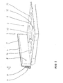
- shows a perspective view of the hob of the cooking appliance, seen from the rear region of the appliance,
- FIG 3
- shows the same perspective view as
FIG 2 but with dismounted hob and with the rear surface of the front panel being broken away, - FIG 4
- shows a side view of the hob of the appliance,
- FIG 5
- shows a view from the rear side of the hob with the front panel and
- FIG 6
- shows a perspective view of the right part of the front panel of the hob with the front surface of the front panel being broken away.
- In the figures a domestic cooking appliance 1 and especially its
hob 2 is depicted. Thehob 2 has fourheating elements surface 6 of thehob 2 is formed by aceramic stove top 18. Thestove top 18 is carried by a frame 19 which is depicted inFIG 3 . - In general the
hob 2 and thus the cooking appliance 1 have a width B and a depth T. - The
hob 2 has afront end 3 which is facing the user during use of the appliance 1. - A
front panel 4 is arranged at thefront end 3 of thehob 2. Thefront panel 4 has anupper edge 5 which is arranged above theupper surface 6 of thehob 2. The height h of theupper edge 5 is shown and being substantial for establishing a protection for children so that they cannot pull down a pot or a pan from thehob 2. The height h of thefront panel 4 is about 25 % of the depth T of thehob 2; a preferred range is between 15 % and 35 % of the depth T. In absolute figures the height h is normally between 90 mm and 135 mm; the depicted solution has a height h of about 113 mm. - Furthermore, the
front panel 4 and more specifically itsfront surface 7 is big enough to receive switching anddisplay elements 9 for controlling the appliance 1. - The
front panel 4 has a substantial triangular shape when viewed from the side as can be seen inFIG 4 . Thefront surface 7 and arear surface 8 have a substantial flat shape. While therear surface 8 extends in vertical direction V, thefront surface 7 is arranged in such a way that its plane extends under a small angle α to the vertical direction V as can be seen inFIG 4 . The angel α is about 20° in the depicted embodiment; the complementary angel β (seeFIG 4 ) to the right angel is thus about 70°. - The
front panel 4 hasside walls 10 which can be best seen inFIG 2 and inFIG 6 . Theside walls 10 haveventilation slots 11 for the flow of air. As can be seen inFIG 6 thefront panel 4 has an opening 13 in thebottom region 12 on both sides of thefront panel 4. Thus,air 20 can flow along a path which is depicted inFIG 6 . This allows an air exhaust from thehob 2 which improves the performance during cooking. - As can be seen in
FIG 3 , openings 21 can be machined into the bottom side of the frame 19. In the depicted embodiment two identical openings 21 are employed in the rear side of the frame 19. Behind the openings 21 fans (not depicted) can be mounted. When the fans are operated, an air flow takes place. As can be seen inFIG 3 air 22 is sucked in by the fans. The air is then transported through the frame 19 and can leave the frame via the ventilation slots 11 (see air 23); reference is made to the air flow depicted inFIG 6 . In the frame 19heating elements - The
front surface 7 offers sufficient space for mounting the necessary switching and/or display elements for operating and controlling the appliance. The space for placing theelements 9 allows a design which is chosen to meet the demands with respect to the aesthetical appearance of the appliance 1. - The
front panel 4 can be made from the sheet metal from with the frame 19 is made, i. e. thefront panel 4 can be one piece together with the frame 19. The production of the structure is economically possible by well-known methods of deforming, deep-drawing and punching of a sheet metal plate. - The invention allows by adding the front panel with the triangular section to the hob to implement all kinds of modern switches and displays, especially those with touch screens and using TFTs.
- The high temperature area (stove top) is remote from the switches and displays so there is no influence from the heat of the stove top. The mounting of the switches and display elements into the front panel is quite easy.
- The view to the display elements is improved due to the arrangement of the front surface of the front panel under the mentioned angle.
- It is practically impossible that a pot of pan is drawn down from the hob by a child due to the mentioned height h of the front panel.
- The exhaust of air is facilitated by the ventilation slots and the circulation of air can easily take place.
- The front panel can also be provided as an add-on part which can be fixed i. e. by a snap connection to an existing hob.
- An advantage of the panel according to the invention is that a glass element used for the panel is not used for the cooking area. As very often the standard cooking surface (ceramic or equivalent) is mainly dark red this limits the possible colours for the displays. Having a panel with a free surface, glass, polycarbonate or equivalents can be used; this allows the use of any colours for the display. I. e. any display can be employed which is trendy, like TFT displays or equivalents.
- The cooking surface can be transparent but it needs a specific coating or enamelling to hide some components, but usually the cost is higher and the display can be in higher ambient temperature.
-
- 1
- Cooking Appliance
- 2
- Hob
- 3
- Front end
- 4
- Front panel
- 5
- Upper edge
- 6
- Upper surface
- 7
- Front surface
- 8
- Rear surface
- 9
- Switching and/or display element
- 10
- Side wall
- 11
- Ventilation slot
- 12
- Bottom region
- 13
- Opening
- 14
- Heating element
- 15
- Heating element
- 16
- Heating element
- 17
- Heating element
- 18
- Ceramic stove top
- 19
- Frame
- 20
- Air
- 21
- Opening
- 22
- Air
- 23
- Air
- h
- Height
- B
- Width
- T
- Depth
- α
- Angel
- β
- Angel
- V
- Vertical direction
Claims (20)
- Cooking appliance (1), especially domestic cooking appliance, having a hob (2) with a front end (3),
characterized in that
a front panel (4) is arranged at the front end (3) of the hob (2), wherein the front panel (4) has an upper edge (5) which is arranged above (h) the upper surface (6) of the hob (2). - Cooking appliance according to claim 1, characterized in that the front panel (4) extends substantial along the whole width (B) of the hob (2).
- Cooking appliance according to claim 1 or 2, characterized in that the front panel (4) comprises a flat front surface (7).
- Cooking appliance according to claim 3, characterized in that the plane of the front surface (7) extends with a small angel (α) to the vertical direction (V).
- Cooking appliance according to claim 4, characterized in that the angel (α) is between 10° and 30°.
- Cooking appliance according to at least one of claims 1 to 5, characterized in that the front panel (4) comprises a flat rear surface (8) facing the hob (2).
- Cooking appliance according to claim 6, characterized in that the plane of the rear surface (8) extends in vertical direction (V).
- Cooking appliance according to at least one of claims 1 to 7, characterized in that the front panel (4) has a substantial triangular form when viewed from the side.
- Cooking appliance according to at least one of claims 1 to 8, characterized in that the height (h) of the upper edge (5) above the upper surface (6) of the hob (2) is between 15 % and 35 % of the depth (T) of the hob (2), preferably between 20 % and 30 %.
- Cooking appliance according to at least one of claims 1 to 9, characterized in that at least one switching and/or display element (9) is arranged in the front surface (7) of the front panel (4).
- Cooking appliance according to claim 10, characterized in that at least one switching element (9) is a touch screen element.
- Cooking appliance according to claim 11, characterized in that the touch screen switching element (9) is of the TFT type.
- Cooking appliance according to at least one of claims 1 to 12, characterized in that the front panel (4) has side walls (10) connecting the front surface (7) and the rear surface (8) of the front panel (4).
- Cooking appliance according to claim 13, characterized in that the side walls (10) comprise at least one ventilation slot (11).
- Cooking appliance according to claim 14, characterized in that at least one ventilation slot (11) is in fluidic connection with a bottom region (12) of the front panel (4).
- Cooking appliance according to claim 15, characterized in that at least one opening (13) is arranged in the bottom region (12) of the front panel (4).
- Cooking appliance according to at least one of claims 1 to 16, characterized in that the hob (2) is equipped with at least one heating element (14, 15, 16, 17).
- Cooking appliance according to claim 17, characterized in that the heating element (14, 15, 16, 17) is an induction heating element.
- Cooking appliance according to at least one of claims 1 to 18, characterized in that the hob is covered by a ceramic stove top (18).
- Cooking appliance according to claim 19, characterized in that the ceramic stove top (18) is free from switching and/or display elements (9).
Priority Applications (3)
| Application Number | Priority Date | Filing Date | Title |
|---|---|---|---|
| AT07023107T ATE504786T1 (en) | 2007-11-29 | 2007-11-29 | COOKING APPARATUS, IN PARTICULAR HOUSEHOLD COOKING APPARATUS |
| EP07023107A EP2065649B1 (en) | 2007-11-29 | 2007-11-29 | Cooking appliance, especially domestic cooking appliance |
| DE602007013779T DE602007013779D1 (en) | 2007-11-29 | 2007-11-29 | Cooking device, in particular household cooking device |
Applications Claiming Priority (1)
| Application Number | Priority Date | Filing Date | Title |
|---|---|---|---|
| EP07023107A EP2065649B1 (en) | 2007-11-29 | 2007-11-29 | Cooking appliance, especially domestic cooking appliance |
Publications (2)
| Publication Number | Publication Date |
|---|---|
| EP2065649A1 true EP2065649A1 (en) | 2009-06-03 |
| EP2065649B1 EP2065649B1 (en) | 2011-04-06 |
Family
ID=40030336
Family Applications (1)
| Application Number | Title | Priority Date | Filing Date |
|---|---|---|---|
| EP07023107A Not-in-force EP2065649B1 (en) | 2007-11-29 | 2007-11-29 | Cooking appliance, especially domestic cooking appliance |
Country Status (3)
| Country | Link |
|---|---|
| EP (1) | EP2065649B1 (en) |
| AT (1) | ATE504786T1 (en) |
| DE (1) | DE602007013779D1 (en) |
Cited By (1)
| Publication number | Priority date | Publication date | Assignee | Title |
|---|---|---|---|---|
| EP2690925A3 (en) * | 2012-07-23 | 2014-09-03 | BSH Bosch und Siemens Hausgeräte GmbH | Hotplate device |
Citations (6)
| Publication number | Priority date | Publication date | Assignee | Title |
|---|---|---|---|---|
| DE8800720U1 (en) | 1988-01-22 | 1988-05-19 | Pichert, Horst, Prof. Dr.-Ing., 8000 München | Cooking area with safety device |
| EP0376791A1 (en) * | 1988-12-27 | 1990-07-04 | Compagnie Europeenne Pour L'equipement Menager "Cepem" | Support for the control means of a household appliance |
| EP0570670A2 (en) | 1992-05-20 | 1993-11-24 | BOSCH-SIEMENS HAUSGERÄTE GmbH | Cooking top |
| DE19961457A1 (en) | 1999-12-20 | 2001-06-21 | Bsh Bosch Siemens Hausgeraete | Built-in cooking hob with movable operating control field fitted at end of support arm element extending from hob surface |
| US6455819B1 (en) | 1998-12-08 | 2002-09-24 | Schott Glas | Cooking apparatus |
| DE10211520A1 (en) | 2002-03-15 | 2003-09-25 | Bsh Bosch Siemens Hausgeraete | Glass ceramic cooking surface |
-
2007
- 2007-11-29 DE DE602007013779T patent/DE602007013779D1/en active Active
- 2007-11-29 EP EP07023107A patent/EP2065649B1/en not_active Not-in-force
- 2007-11-29 AT AT07023107T patent/ATE504786T1/en not_active IP Right Cessation
Patent Citations (7)
| Publication number | Priority date | Publication date | Assignee | Title |
|---|---|---|---|---|
| DE8800720U1 (en) | 1988-01-22 | 1988-05-19 | Pichert, Horst, Prof. Dr.-Ing., 8000 München | Cooking area with safety device |
| EP0376791A1 (en) * | 1988-12-27 | 1990-07-04 | Compagnie Europeenne Pour L'equipement Menager "Cepem" | Support for the control means of a household appliance |
| EP0376791B1 (en) | 1988-12-27 | 1992-03-25 | Compagnie Europeenne Pour L'equipement Menager "Cepem" | Support for the control means of a household appliance |
| EP0570670A2 (en) | 1992-05-20 | 1993-11-24 | BOSCH-SIEMENS HAUSGERÄTE GmbH | Cooking top |
| US6455819B1 (en) | 1998-12-08 | 2002-09-24 | Schott Glas | Cooking apparatus |
| DE19961457A1 (en) | 1999-12-20 | 2001-06-21 | Bsh Bosch Siemens Hausgeraete | Built-in cooking hob with movable operating control field fitted at end of support arm element extending from hob surface |
| DE10211520A1 (en) | 2002-03-15 | 2003-09-25 | Bsh Bosch Siemens Hausgeraete | Glass ceramic cooking surface |
Cited By (1)
| Publication number | Priority date | Publication date | Assignee | Title |
|---|---|---|---|---|
| EP2690925A3 (en) * | 2012-07-23 | 2014-09-03 | BSH Bosch und Siemens Hausgeräte GmbH | Hotplate device |
Also Published As
| Publication number | Publication date |
|---|---|
| EP2065649B1 (en) | 2011-04-06 |
| DE602007013779D1 (en) | 2011-05-19 |
| ATE504786T1 (en) | 2011-04-15 |
Similar Documents
| Publication | Publication Date | Title |
|---|---|---|
| US8269148B2 (en) | Cooktop with forced convection cooling | |
| US6067980A (en) | Gas cooking appliance | |
| US20180266697A1 (en) | Toaster oven | |
| EP2102554B1 (en) | Built-in cooking appliance | |
| EP0549933A1 (en) | Oven door | |
| CN116134269A (en) | Doors and household cooking appliances | |
| EP2065649B1 (en) | Cooking appliance, especially domestic cooking appliance | |
| JP5030700B2 (en) | Cooker | |
| US11009235B2 (en) | Domestic kitchen appliance with sidewall cooling | |
| JP2002089854A (en) | Built-in heater | |
| JP5393762B2 (en) | Cooker | |
| JP6846679B2 (en) | Partition panel, partition panel mounting method and partition panel mounting structure | |
| KR100500593B1 (en) | Glass top plate for cooking stove with grill | |
| JP2018173202A (en) | Heating cooker | |
| CN101573562B (en) | built-in cooking appliances | |
| CN216439032U (en) | Lid and have its cooking utensil | |
| KR100829622B1 (en) | Built-in cooker | |
| CN220608148U (en) | Inner pot assembly of air fryer | |
| KR100826705B1 (en) | Built-in cookers and their installation devices | |
| EP4474716A1 (en) | Cooking apparatus | |
| EP4474710A1 (en) | Cooking apparatus | |
| EP2102559B1 (en) | Built-in cooking appliance | |
| KR20030023452A (en) | Built-in range | |
| EP2097679B1 (en) | Built-in cooking appliance | |
| KR100826706B1 (en) | Built-in cooker |
Legal Events
| Date | Code | Title | Description |
|---|---|---|---|
| PUAI | Public reference made under article 153(3) epc to a published international application that has entered the european phase |
Free format text: ORIGINAL CODE: 0009012 |
|
| 17P | Request for examination filed |
Effective date: 20090121 |
|
| AK | Designated contracting states |
Kind code of ref document: A1 Designated state(s): AT BE BG CH CY CZ DE DK EE ES FI FR GB GR HU IE IS IT LI LT LU LV MC MT NL PL PT RO SE SI SK TR |
|
| AX | Request for extension of the european patent |
Extension state: AL BA HR MK RS |
|
| AKX | Designation fees paid |
Designated state(s): AT BE BG CH CY CZ DE DK EE ES FI FR GB GR HU IE IS IT LI LT LU LV MC MT NL PL PT RO SE SI SK TR |
|
| GRAP | Despatch of communication of intention to grant a patent |
Free format text: ORIGINAL CODE: EPIDOSNIGR1 |
|
| GRAS | Grant fee paid |
Free format text: ORIGINAL CODE: EPIDOSNIGR3 |
|
| GRAA | (expected) grant |
Free format text: ORIGINAL CODE: 0009210 |
|
| RAP1 | Party data changed (applicant data changed or rights of an application transferred) |
Owner name: ELECTROLUX HOME PRODUCTS CORPORATION N.V. |
|
| AK | Designated contracting states |
Kind code of ref document: B1 Designated state(s): AT BE BG CH CY CZ DE DK EE ES FI FR GB GR HU IE IS IT LI LT LU LV MC MT NL PL PT RO SE SI SK TR |
|
| REG | Reference to a national code |
Ref country code: GB Ref legal event code: FG4D |
|
| REG | Reference to a national code |
Ref country code: CH Ref legal event code: EP |
|
| REG | Reference to a national code |
Ref country code: IE Ref legal event code: FG4D |
|
| REF | Corresponds to: |
Ref document number: 602007013779 Country of ref document: DE Date of ref document: 20110519 Kind code of ref document: P |
|
| REG | Reference to a national code |
Ref country code: DE Ref legal event code: R096 Ref document number: 602007013779 Country of ref document: DE Effective date: 20110519 |
|
| REG | Reference to a national code |
Ref country code: SE Ref legal event code: TRGR |
|
| RAP2 | Party data changed (patent owner data changed or rights of a patent transferred) |
Owner name: ELECTROLUX HOME PRODUCTS CORPORATION N.V. |
|
| REG | Reference to a national code |
Ref country code: NL Ref legal event code: VDEP Effective date: 20110406 |
|
| PG25 | Lapsed in a contracting state [announced via postgrant information from national office to epo] |
Ref country code: SI Free format text: LAPSE BECAUSE OF FAILURE TO SUBMIT A TRANSLATION OF THE DESCRIPTION OR TO PAY THE FEE WITHIN THE PRESCRIBED TIME-LIMIT Effective date: 20110406 |
|
| LTIE | Lt: invalidation of european patent or patent extension |
Effective date: 20110406 |
|
| PG25 | Lapsed in a contracting state [announced via postgrant information from national office to epo] |
Ref country code: PT Free format text: LAPSE BECAUSE OF FAILURE TO SUBMIT A TRANSLATION OF THE DESCRIPTION OR TO PAY THE FEE WITHIN THE PRESCRIBED TIME-LIMIT Effective date: 20110808 Ref country code: LT Free format text: LAPSE BECAUSE OF FAILURE TO SUBMIT A TRANSLATION OF THE DESCRIPTION OR TO PAY THE FEE WITHIN THE PRESCRIBED TIME-LIMIT Effective date: 20110406 |
|
| PG25 | Lapsed in a contracting state [announced via postgrant information from national office to epo] |
Ref country code: GR Free format text: LAPSE BECAUSE OF FAILURE TO SUBMIT A TRANSLATION OF THE DESCRIPTION OR TO PAY THE FEE WITHIN THE PRESCRIBED TIME-LIMIT Effective date: 20110707 Ref country code: AT Free format text: LAPSE BECAUSE OF FAILURE TO SUBMIT A TRANSLATION OF THE DESCRIPTION OR TO PAY THE FEE WITHIN THE PRESCRIBED TIME-LIMIT Effective date: 20110406 Ref country code: CY Free format text: LAPSE BECAUSE OF FAILURE TO SUBMIT A TRANSLATION OF THE DESCRIPTION OR TO PAY THE FEE WITHIN THE PRESCRIBED TIME-LIMIT Effective date: 20110406 Ref country code: IS Free format text: LAPSE BECAUSE OF FAILURE TO SUBMIT A TRANSLATION OF THE DESCRIPTION OR TO PAY THE FEE WITHIN THE PRESCRIBED TIME-LIMIT Effective date: 20110806 Ref country code: ES Free format text: LAPSE BECAUSE OF FAILURE TO SUBMIT A TRANSLATION OF THE DESCRIPTION OR TO PAY THE FEE WITHIN THE PRESCRIBED TIME-LIMIT Effective date: 20110717 Ref country code: FI Free format text: LAPSE BECAUSE OF FAILURE TO SUBMIT A TRANSLATION OF THE DESCRIPTION OR TO PAY THE FEE WITHIN THE PRESCRIBED TIME-LIMIT Effective date: 20110406 Ref country code: LV Free format text: LAPSE BECAUSE OF FAILURE TO SUBMIT A TRANSLATION OF THE DESCRIPTION OR TO PAY THE FEE WITHIN THE PRESCRIBED TIME-LIMIT Effective date: 20110406 Ref country code: BE Free format text: LAPSE BECAUSE OF FAILURE TO SUBMIT A TRANSLATION OF THE DESCRIPTION OR TO PAY THE FEE WITHIN THE PRESCRIBED TIME-LIMIT Effective date: 20110406 |
|
| PG25 | Lapsed in a contracting state [announced via postgrant information from national office to epo] |
Ref country code: NL Free format text: LAPSE BECAUSE OF FAILURE TO SUBMIT A TRANSLATION OF THE DESCRIPTION OR TO PAY THE FEE WITHIN THE PRESCRIBED TIME-LIMIT Effective date: 20110406 |
|
| PG25 | Lapsed in a contracting state [announced via postgrant information from national office to epo] |
Ref country code: CZ Free format text: LAPSE BECAUSE OF FAILURE TO SUBMIT A TRANSLATION OF THE DESCRIPTION OR TO PAY THE FEE WITHIN THE PRESCRIBED TIME-LIMIT Effective date: 20110406 Ref country code: EE Free format text: LAPSE BECAUSE OF FAILURE TO SUBMIT A TRANSLATION OF THE DESCRIPTION OR TO PAY THE FEE WITHIN THE PRESCRIBED TIME-LIMIT Effective date: 20110406 |
|
| PGFP | Annual fee paid to national office [announced via postgrant information from national office to epo] |
Ref country code: FR Payment date: 20111130 Year of fee payment: 5 Ref country code: SE Payment date: 20111128 Year of fee payment: 5 |
|
| PLBE | No opposition filed within time limit |
Free format text: ORIGINAL CODE: 0009261 |
|
| STAA | Information on the status of an ep patent application or granted ep patent |
Free format text: STATUS: NO OPPOSITION FILED WITHIN TIME LIMIT |
|
| REG | Reference to a national code |
Ref country code: FR Ref legal event code: CA Effective date: 20120116 |
|
| PG25 | Lapsed in a contracting state [announced via postgrant information from national office to epo] |
Ref country code: SK Free format text: LAPSE BECAUSE OF FAILURE TO SUBMIT A TRANSLATION OF THE DESCRIPTION OR TO PAY THE FEE WITHIN THE PRESCRIBED TIME-LIMIT Effective date: 20110406 Ref country code: PL Free format text: LAPSE BECAUSE OF FAILURE TO SUBMIT A TRANSLATION OF THE DESCRIPTION OR TO PAY THE FEE WITHIN THE PRESCRIBED TIME-LIMIT Effective date: 20110406 Ref country code: RO Free format text: LAPSE BECAUSE OF FAILURE TO SUBMIT A TRANSLATION OF THE DESCRIPTION OR TO PAY THE FEE WITHIN THE PRESCRIBED TIME-LIMIT Effective date: 20110406 Ref country code: DK Free format text: LAPSE BECAUSE OF FAILURE TO SUBMIT A TRANSLATION OF THE DESCRIPTION OR TO PAY THE FEE WITHIN THE PRESCRIBED TIME-LIMIT Effective date: 20110406 |
|
| 26N | No opposition filed |
Effective date: 20120110 |
|
| REG | Reference to a national code |
Ref country code: DE Ref legal event code: R097 Ref document number: 602007013779 Country of ref document: DE Effective date: 20120110 |
|
| REG | Reference to a national code |
Ref country code: DE Ref legal event code: R082 Ref document number: 602007013779 Country of ref document: DE Representative=s name: GERHARD BAUMGARTL, DE Ref country code: DE Ref legal event code: R082 Ref document number: 602007013779 Country of ref document: DE Representative=s name: BAUMGARTL, GERHARD, DIPL.-ING.UNIV., DE |
|
| PG25 | Lapsed in a contracting state [announced via postgrant information from national office to epo] |
Ref country code: MC Free format text: LAPSE BECAUSE OF NON-PAYMENT OF DUE FEES Effective date: 20111130 |
|
| PGFP | Annual fee paid to national office [announced via postgrant information from national office to epo] |
Ref country code: IT Payment date: 20111121 Year of fee payment: 5 |
|
| REG | Reference to a national code |
Ref country code: CH Ref legal event code: PL |
|
| PG25 | Lapsed in a contracting state [announced via postgrant information from national office to epo] |
Ref country code: CH Free format text: LAPSE BECAUSE OF NON-PAYMENT OF DUE FEES Effective date: 20111130 Ref country code: LI Free format text: LAPSE BECAUSE OF NON-PAYMENT OF DUE FEES Effective date: 20111130 |
|
| REG | Reference to a national code |
Ref country code: IE Ref legal event code: MM4A |
|
| PG25 | Lapsed in a contracting state [announced via postgrant information from national office to epo] |
Ref country code: IE Free format text: LAPSE BECAUSE OF NON-PAYMENT OF DUE FEES Effective date: 20111129 |
|
| PG25 | Lapsed in a contracting state [announced via postgrant information from national office to epo] |
Ref country code: MT Free format text: LAPSE BECAUSE OF FAILURE TO SUBMIT A TRANSLATION OF THE DESCRIPTION OR TO PAY THE FEE WITHIN THE PRESCRIBED TIME-LIMIT Effective date: 20110406 |
|
| PG25 | Lapsed in a contracting state [announced via postgrant information from national office to epo] |
Ref country code: LU Free format text: LAPSE BECAUSE OF NON-PAYMENT OF DUE FEES Effective date: 20111129 |
|
| PG25 | Lapsed in a contracting state [announced via postgrant information from national office to epo] |
Ref country code: BG Free format text: LAPSE BECAUSE OF FAILURE TO SUBMIT A TRANSLATION OF THE DESCRIPTION OR TO PAY THE FEE WITHIN THE PRESCRIBED TIME-LIMIT Effective date: 20110706 |
|
| GBPC | Gb: european patent ceased through non-payment of renewal fee |
Effective date: 20121129 |
|
| PG25 | Lapsed in a contracting state [announced via postgrant information from national office to epo] |
Ref country code: SE Free format text: LAPSE BECAUSE OF NON-PAYMENT OF DUE FEES Effective date: 20121130 |
|
| REG | Reference to a national code |
Ref country code: FR Ref legal event code: ST Effective date: 20130731 |
|
| PG25 | Lapsed in a contracting state [announced via postgrant information from national office to epo] |
Ref country code: IT Free format text: LAPSE BECAUSE OF NON-PAYMENT OF DUE FEES Effective date: 20121129 |
|
| REG | Reference to a national code |
Ref country code: DE Ref legal event code: R119 Ref document number: 602007013779 Country of ref document: DE Effective date: 20130601 |
|
| PG25 | Lapsed in a contracting state [announced via postgrant information from national office to epo] |
Ref country code: TR Free format text: LAPSE BECAUSE OF FAILURE TO SUBMIT A TRANSLATION OF THE DESCRIPTION OR TO PAY THE FEE WITHIN THE PRESCRIBED TIME-LIMIT Effective date: 20110406 |
|
| PG25 | Lapsed in a contracting state [announced via postgrant information from national office to epo] |
Ref country code: HU Free format text: LAPSE BECAUSE OF FAILURE TO SUBMIT A TRANSLATION OF THE DESCRIPTION OR TO PAY THE FEE WITHIN THE PRESCRIBED TIME-LIMIT Effective date: 20110406 Ref country code: DE Free format text: LAPSE BECAUSE OF NON-PAYMENT OF DUE FEES Effective date: 20130601 |
|
| PG25 | Lapsed in a contracting state [announced via postgrant information from national office to epo] |
Ref country code: GB Free format text: LAPSE BECAUSE OF NON-PAYMENT OF DUE FEES Effective date: 20121129 Ref country code: FR Free format text: LAPSE BECAUSE OF NON-PAYMENT OF DUE FEES Effective date: 20121130 |