EP2065633A1 - Bulb-type led lamp and compact led lamp - Google Patents
Bulb-type led lamp and compact led lamp Download PDFInfo
- Publication number
- EP2065633A1 EP2065633A1 EP07807518A EP07807518A EP2065633A1 EP 2065633 A1 EP2065633 A1 EP 2065633A1 EP 07807518 A EP07807518 A EP 07807518A EP 07807518 A EP07807518 A EP 07807518A EP 2065633 A1 EP2065633 A1 EP 2065633A1
- Authority
- EP
- European Patent Office
- Prior art keywords
- intensity led
- led modules
- intensity
- bulb
- led lamp
- Prior art date
- Legal status (The legal status is an assumption and is not a legal conclusion. Google has not performed a legal analysis and makes no representation as to the accuracy of the status listed.)
- Granted
Links
Images




Classifications
-
- F—MECHANICAL ENGINEERING; LIGHTING; HEATING; WEAPONS; BLASTING
- F21—LIGHTING
- F21V—FUNCTIONAL FEATURES OR DETAILS OF LIGHTING DEVICES OR SYSTEMS THEREOF; STRUCTURAL COMBINATIONS OF LIGHTING DEVICES WITH OTHER ARTICLES, NOT OTHERWISE PROVIDED FOR
- F21V23/00—Arrangement of electric circuit elements in or on lighting devices
-
- F—MECHANICAL ENGINEERING; LIGHTING; HEATING; WEAPONS; BLASTING
- F21—LIGHTING
- F21K—NON-ELECTRIC LIGHT SOURCES USING LUMINESCENCE; LIGHT SOURCES USING ELECTROCHEMILUMINESCENCE; LIGHT SOURCES USING CHARGES OF COMBUSTIBLE MATERIAL; LIGHT SOURCES USING SEMICONDUCTOR DEVICES AS LIGHT-GENERATING ELEMENTS; LIGHT SOURCES NOT OTHERWISE PROVIDED FOR
- F21K9/00—Light sources using semiconductor devices as light-generating elements, e.g. using light-emitting diodes [LED] or lasers
- F21K9/20—Light sources comprising attachment means
- F21K9/23—Retrofit light sources for lighting devices with a single fitting for each light source, e.g. for substitution of incandescent lamps with bayonet or threaded fittings
- F21K9/232—Retrofit light sources for lighting devices with a single fitting for each light source, e.g. for substitution of incandescent lamps with bayonet or threaded fittings specially adapted for generating an essentially omnidirectional light distribution, e.g. with a glass bulb
-
- F—MECHANICAL ENGINEERING; LIGHTING; HEATING; WEAPONS; BLASTING
- F21—LIGHTING
- F21K—NON-ELECTRIC LIGHT SOURCES USING LUMINESCENCE; LIGHT SOURCES USING ELECTROCHEMILUMINESCENCE; LIGHT SOURCES USING CHARGES OF COMBUSTIBLE MATERIAL; LIGHT SOURCES USING SEMICONDUCTOR DEVICES AS LIGHT-GENERATING ELEMENTS; LIGHT SOURCES NOT OTHERWISE PROVIDED FOR
- F21K9/00—Light sources using semiconductor devices as light-generating elements, e.g. using light-emitting diodes [LED] or lasers
- F21K9/60—Optical arrangements integrated in the light source, e.g. for improving the colour rendering index or the light extraction
- F21K9/61—Optical arrangements integrated in the light source, e.g. for improving the colour rendering index or the light extraction using light guides
-
- F—MECHANICAL ENGINEERING; LIGHTING; HEATING; WEAPONS; BLASTING
- F21—LIGHTING
- F21V—FUNCTIONAL FEATURES OR DETAILS OF LIGHTING DEVICES OR SYSTEMS THEREOF; STRUCTURAL COMBINATIONS OF LIGHTING DEVICES WITH OTHER ARTICLES, NOT OTHERWISE PROVIDED FOR
- F21V29/00—Protecting lighting devices from thermal damage; Cooling or heating arrangements specially adapted for lighting devices or systems
- F21V29/50—Cooling arrangements
- F21V29/502—Cooling arrangements characterised by the adaptation for cooling of specific components
- F21V29/507—Cooling arrangements characterised by the adaptation for cooling of specific components of means for protecting lighting devices from damage, e.g. housings
-
- F—MECHANICAL ENGINEERING; LIGHTING; HEATING; WEAPONS; BLASTING
- F21—LIGHTING
- F21V—FUNCTIONAL FEATURES OR DETAILS OF LIGHTING DEVICES OR SYSTEMS THEREOF; STRUCTURAL COMBINATIONS OF LIGHTING DEVICES WITH OTHER ARTICLES, NOT OTHERWISE PROVIDED FOR
- F21V29/00—Protecting lighting devices from thermal damage; Cooling or heating arrangements specially adapted for lighting devices or systems
- F21V29/50—Cooling arrangements
- F21V29/70—Cooling arrangements characterised by passive heat-dissipating elements, e.g. heat-sinks
-
- F—MECHANICAL ENGINEERING; LIGHTING; HEATING; WEAPONS; BLASTING
- F21—LIGHTING
- F21V—FUNCTIONAL FEATURES OR DETAILS OF LIGHTING DEVICES OR SYSTEMS THEREOF; STRUCTURAL COMBINATIONS OF LIGHTING DEVICES WITH OTHER ARTICLES, NOT OTHERWISE PROVIDED FOR
- F21V29/00—Protecting lighting devices from thermal damage; Cooling or heating arrangements specially adapted for lighting devices or systems
- F21V29/85—Protecting lighting devices from thermal damage; Cooling or heating arrangements specially adapted for lighting devices or systems characterised by the material
- F21V29/89—Metals
-
- F—MECHANICAL ENGINEERING; LIGHTING; HEATING; WEAPONS; BLASTING
- F21—LIGHTING
- F21Y—INDEXING SCHEME ASSOCIATED WITH SUBCLASSES F21K, F21L, F21S and F21V, RELATING TO THE FORM OR THE KIND OF THE LIGHT SOURCES OR OF THE COLOUR OF THE LIGHT EMITTED
- F21Y2115/00—Light-generating elements of semiconductor light sources
- F21Y2115/10—Light-emitting diodes [LED]
Definitions
- the present invention relates to a bulb-shaped LED lamp and a compact LED lamp where light-emitting diodes (LEDs) are used as a light source.
- LEDs light-emitting diodes
- a LED bulb provided with an LED light-emitting portion having a plurality of light-emitting diode devices for emitting near-ultraviolet light or blue light, which are arranged in a plane manner, a flat face portion disposed at a position spaced from a face on which the light-emitting diode devices are arranged by a predetermined distance so as to face the light-emitting diode devices, and a wavelength-converting cover provided on its flat face portion with fluorescence substance for wavelength-converting light emitted from the light-emitting diode devices (for example, see Patent Reference 1).
- the LED lamp proposed above has the following problems.
- the present invention has been made to solve the abovementioned problems and an object thereof is to provide a bulb-shaped LED lamp which improves brightness and can obtain brightness corresponding to a filament bulb of 40 watts to 60 watts and a compact LED lamp.
- a bulb-shaped LED lamp comprises a plurality of high-intensity LED modules where a high-intensity LED is attached on an LED fixing base plate; a heat sink where the high-intensity LED modules are attached on one end face in an axial direction thereof along a circumferential direction, for performing radiation of the high-intensity LED modules; a reflector which is provided so as to surround the plurality of high-intensity LED modules, for guiding light from the high-intensity LED modules forward; an electronic circuit for driving which drives the high-intensity LED modules; a housing which houses the heat sink, the electronic circuit for driving, a portion of the reflector therein; and a globe which configures an outer shell together with the housing.
- the bulb-shaped LED lamp according to the present invention has a configuration that a diffusion sheet is used as the reflector.
- a bulb-shaped LED lamp comprises a plurality of high-intensity LED modules where a high-intensity LED is attached on an LED fixing base plate, each being provided around a high-intensity LED with a reflector for guiding light forward; a heat sink on which the high-intensity LED modules are attached on an end face in an axial direction thereof along a circumferential direction, for performing radiation of the high-intensity LED modules; an electronic circuit for driving which drives the high-intensity LED modules; a housing which houses the heat sink and the electronic circuit for driving; and a glass globe which configures an outer shell together with the housing.
- a compact LED lamp comprises a plurality of high-intensity LED modules where a high-intensity LED is attached on an LED fixing base plate; a heat sink where the high-intensity LED modules are attached on an end face in an axial direction thereof along a circumferential direction, for performing radiation of the high-intensity LED modules; a reflector which is provided so as to surround the plurality of high-intensity LED modules, for guiding light from the high-intensity LED modules forward; a resin light-guiding blade member having the same number of blades as the number of high-intensity LED modules, where the blades are provided radially in a diametrical direction at approximately equal intervals, the blades have predetermined heights in the axial direction, and the respective blades are fixed on the high-intensity LED modules; an electronic circuit for driving which drives the high-intensity LED modules; and a housing which houses the heat sink, the electronic circuit for driving, a portion of the reflector therein
- the bulb-shaped LED lamp according to the present invention can achieve such an effect that brightness is improved and brightness corresponding to a filament bulb of 40 watts to 60 watts can be obtained according to improvement of luminance of the high-intensity LEDs.
- light from the high-intensity LED modules can be taken out laterally and forward efficiently by the resin light-guiding blade member having the same number of blades as the number of the high-intensity LED modules.
- Fig. 1 and Fig. 2 show a first embodiment.
- Fig. 1 shows a front view of a bulb-shaped LED lamp 1 and
- Fig. 2 shows a sectional view taken along line A-A in Fig. 1 .
- a light source of the bulb-shaped LED lamp 1 is a high-intensity LED module 2 where a high-intensity LED 2a is attached on an LED fixing base plate 2b.
- Six high-intensity LED modules 2 are used here. Brightness of the high-intensity LED 2a has 20 lm (lumen) per one piece at present, and the brightness reaches only 120 lm even when six high-intensity LEDs are used, but it is expected that luminance of the high-intensity LED 2a is rapidly raised in the near future.
- illuminance corresponding to a filament bulb of 40 to 60 watts is obtained under such a condition that a distance between a subject and the bulb-shaped LED lamp 1 is in a range of 1 m to 2 m and a distance in circumferential direction is about 2 m by the bulb-shaped LED lamp 1 of a configuration in Fig. 1 and Fig. 2 .
- LED fixing base plates 2b are fixed on the heat sink 5 by adhesive or the like.
- the LED fixing base plate 2b is made from metal, polyimide resin, or the like.
- the heat sink 5 is a radiator plate made from, for example, aluminum, and heat generated from the high-intensity LED module 2 is transmitted and radiated efficiently.
- a housing 7 is provided so as to surround the heat sink 5.
- the housing 7 is made from PBT (polybutylene terephthalate) resin or such metal as aluminum.
- the housing 7 is provided therein with not only the heat sink 5 but also an electronic circuit for driving 6 that adjusts power taken in from an external power source to current/voltage for lighting each high-intensity LED 2a to supply the same to each high-intensity LED 2a. Since the electronic circuit for driving 6 is a known one, explanation thereof is omitted.
- the respective high-intensity LED modules 2 are surrounded by a reflector 4 optimized for efficiently taking out light from each high-intensity LED 2a forward.
- the reflector 4 is made of, for example, a diffusion sheet made from polycarbonate (PC), molded resin, or metal such as stainless steel. Lateral leakage of light from the high-intensity LEDs 2a is suppressed by the reflector 4, so that light can be efficiently taken out forward.
- a globe 8 is attached to the outside of the reflector 4, and it configures an outer shell of a bulb-shaped LED lamp together with the housing 7.
- Material of the globe 8 is resin, glass, or the like.
- the housing 7 is attached with an E26 base.
- An E17 base may be used instead of the E26 base.
- the housing 7 is made from resin, radiation from resin surface is insufficient, so that thermally-conductive silicon rubber is filled in the housing 7, thereby coupling the heat sink 5 and the E26 base 9 thermally.
- the bulb-shaped LED lamp 1 uses the high-intensity LED modules 2, where light can be taken out forward efficiently by the reflector 4 suppressing lateral leakage of light from the high-intensity LEDs 2a, it is expected that, when luminance of a high-intensity LED2a is raised in the future, illuminance corresponding to a filament bulb of 40 to 60 watts can be obtained under such a condition that a distance between a subject and the bulb-shaped LED lamp 1 is in a range of 1 m to 2 m and a distance in a circumferential direction is about 2 m.
- Fig. 3 and Fig. 4 show a second embodiment.
- Fig. 3 shows a front view of a compact LED lamp 10
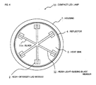
- Fig. 4 shows a plan view of the compact LED lamp 10 viewed from the front thereof.
- the compact LED lamp 10 is different from the bulb-shaped LED lamp 1 in Fig. 1 in that the former does not have the globe 8 and it is provided with a resin light-guiding blade member 11.
- the other configuration of the second embodiment is the same as that of the first embodiment.
- the resin light-guiding blade member 11 has six blades 11a as shown in Fig. 4 , where the blades 11a are provided radially in a diametrical direction at almost equal intervals.
- the blades 11a are set to predetermined heights in an axial direction (a height direction).
- Each blade 11a is bonded and fixed on the high-intensity LED module 2.
- Light from the high-intensity LED modules 2 is guided efficiently by the resin light-guiding blade member 11 so that light can be taken out in a lateral direction (a diametrical direction) and in a forward direction.
- the resin light-guiding blade member 11 serves to diffuse light from the high-intensity LED modules 2 properly and serves to guide the light.
- the compact LED lamp 10 can take out light from the high-intensity LED modules 2 in a lateral direction and a forward direction by the resin light-guiding blade member 11 having the same number of blades as the number of high-intensity LED modules 2.
- Fig. 5 and Fig. 6 show a third embodiment.
- Fig. 5 shows a plan view of a bulb-shaped LED lamp 1 and
- Fig. 6 shows a sectional view taken along line B-B in Fig. 5 .
- the reflector 4 is provided so as to surround all of the high-intensity LED modules 2, but reflecting plates 2c may be provided for individual high-intensity LED modules 2 instead of the reflector 4.
- each high-intensity LED module 2 each have a horn-shaped reflecting plate 2c for guiding light forward around the high-intensity LED 2a. Since each high-intensity LED module 2 has the reflecting plate 2c for guiding light forward, the reflector 4 may be removed.
- the high-intensity LED 2a is provided on the LED fixing base plate 2b and the horn-shaped reflecting plate 2c is provided around the high-intensity LED 2a.
- the LED fixing base plate 2b is bonded and fixed to the heat sink 5 by, for example, a double-faced adhesive tape.
- the horn-shaped reflecting plates 2c for guiding light forward are provided around the high-intensity LEDs 2a of the individual high-intensity LED modules 2, thereby the reflector 4 used in the first embodiment can be removed.
- both the horn-shaped reflecting plates 2c for guiding light forward provided around the high-intensity LEDs 2a of the individual high-intensity LED modules 2 and the reflector 4 surrounding all of the high-intensity LED modules 2 may be used.
Landscapes
- Engineering & Computer Science (AREA)
- General Engineering & Computer Science (AREA)
- Physics & Mathematics (AREA)
- Microelectronics & Electronic Packaging (AREA)
- Optics & Photonics (AREA)
- Non-Portable Lighting Devices Or Systems Thereof (AREA)
- Arrangement Of Elements, Cooling, Sealing, Or The Like Of Lighting Devices (AREA)
- Led Device Packages (AREA)
Abstract
Description
- The present invention relates to a bulb-shaped LED lamp and a compact LED lamp where light-emitting diodes (LEDs) are used as a light source.
- In order to make luminance of light wavelength-converted by a wave-conversion cover approximately even and achieve a long operating life of fluorescence substance and light-emitting diode devices, there has been proposed a LED bulb provided with an LED light-emitting portion having a plurality of light-emitting diode devices for emitting near-ultraviolet light or blue light, which are arranged in a plane manner, a flat face portion disposed at a position spaced from a face on which the light-emitting diode devices are arranged by a predetermined distance so as to face the light-emitting diode devices, and a wavelength-converting cover provided on its flat face portion with fluorescence substance for wavelength-converting light emitted from the light-emitting diode devices (for example, see Patent Reference 1).
- Patent Reference 1:
JP-A-2006-156187 - However, the LED lamp proposed above has the following problems.
- Since a large amount of light emitted from the LED light-emitting portion of the LED bulb leaks from a glass globe laterally, it is impossible to take out light in a front direction efficiently.
- The present invention has been made to solve the abovementioned problems and an object thereof is to provide a bulb-shaped LED lamp which improves brightness and can obtain brightness corresponding to a filament bulb of 40 watts to 60 watts and a compact LED lamp.
- A bulb-shaped LED lamp according to the present invention comprises a plurality of high-intensity LED modules where a high-intensity LED is attached on an LED fixing base plate; a heat sink where the high-intensity LED modules are attached on one end face in an axial direction thereof along a circumferential direction, for performing radiation of the high-intensity LED modules; a reflector which is provided so as to surround the plurality of high-intensity LED modules, for guiding light from the high-intensity LED modules forward; an electronic circuit for driving which drives the high-intensity LED modules; a housing which houses the heat sink, the electronic circuit for driving, a portion of the reflector therein; and a globe which configures an outer shell together with the housing.
- The bulb-shaped LED lamp according to the present invention has a configuration that a diffusion sheet is used as the reflector.
- A bulb-shaped LED lamp according to the present invention comprises a plurality of high-intensity LED modules where a high-intensity LED is attached on an LED fixing base plate, each being provided around a high-intensity LED with a reflector for guiding light forward; a heat sink on which the high-intensity LED modules are attached on an end face in an axial direction thereof along a circumferential direction, for performing radiation of the high-intensity LED modules; an electronic circuit for driving which drives the high-intensity LED modules; a housing which houses the heat sink and the electronic circuit for driving; and a glass globe which configures an outer shell together with the housing.
- A compact LED lamp according to the present invention comprises a plurality of high-intensity LED modules where a high-intensity LED is attached on an LED fixing base plate; a heat sink where the high-intensity LED modules are attached on an end face in an axial direction thereof along a circumferential direction, for performing radiation of the high-intensity LED modules; a reflector which is provided so as to surround the plurality of high-intensity LED modules, for guiding light from the high-intensity LED modules forward; a resin light-guiding blade member having the same number of blades as the number of high-intensity LED modules, where the blades are provided radially in a diametrical direction at approximately equal intervals, the blades have predetermined heights in the axial direction, and the respective blades are fixed on the high-intensity LED modules; an electronic circuit for driving which drives the high-intensity LED modules; and a housing which houses the heat sink, the electronic circuit for driving, a portion of the reflector therein.
- With the abovementioned configuration, the bulb-shaped LED lamp according to the present invention can achieve such an effect that brightness is improved and brightness corresponding to a filament bulb of 40 watts to 60 watts can be obtained according to improvement of luminance of the high-intensity LEDs.
- In the compact LED lamp according to the present invention, light from the high-intensity LED modules can be taken out laterally and forward efficiently by the resin light-guiding blade member having the same number of blades as the number of the high-intensity LED modules.
-
-
Fig. 1 shows a first embodiment and a front view of a bulb-shaped LED lamp 1. -
Fig. 2 shows the first embodiment and a sectional view taken along line A-A inFig. 1 . -
Fig. 3 shows a second embodiment and a front view of acompact LED lamp 10. -
FIG. 4 shows the second embodiment and a plan view of thecompact LED 10 lamp viewed from the front thereof. -
Fig. 5 shows a third embodiment and a plan view of a bulb-shaped LED lamp 1. -
Fig. 6 shows the third embodiment and a sectional view taken along line B-B inFig. 5 . - 1: bulb-shaped LED lamp, 2: high-intensity LED module, 2a: high-intensity LED, 2b: LED fixing base plate, 2c: reflecting plate, 4: reflector, 5: heat sink, 6: electronic circuit for driving, 7: housing, 8: globe, 9: E26 base, 10: compact LED lamp, 11: resin light-guiding blade member, 11a: blade
-
Fig. 1 andFig. 2 show a first embodiment.Fig. 1 shows a front view of a bulb-shaped LED lamp 1 andFig. 2 shows a sectional view taken along line A-A inFig. 1 . - As shown in
Fig. 1 andFig. 2 , a light source of the bulb-shaped LED lamp 1 is a high-intensity LED module 2 where a high-intensity LED 2a is attached on an LEDfixing base plate 2b. Six high-intensity LED modules 2 are used here. Brightness of the high-intensity LED 2a has 20 lm (lumen) per one piece at present, and the brightness reaches only 120 lm even when six high-intensity LEDs are used, but it is expected that luminance of the high-intensity LED 2a is rapidly raised in the near future. For example, when the brightness of the high-intensity LED 2a reaches a value corresponding to 100 lm per one piece, illuminance corresponding to a filament bulb of 40 to 60 watts is obtained under such a condition that a distance between a subject and the bulb-shaped LED lamp 1 is in a range of 1 m to 2 m and a distance in circumferential direction is about 2 m by the bulb-shaped LED lamp 1 of a configuration inFig. 1 andFig. 2 . - Six high-
intensity LED modules 2 are arranged and fixed on an end face of aheat sink 5 in an axial direction thereof along a circumferential direction. LEDfixing base plates 2b are fixed on theheat sink 5 by adhesive or the like. The LEDfixing base plate 2b is made from metal, polyimide resin, or the like. Theheat sink 5 is a radiator plate made from, for example, aluminum, and heat generated from the high-intensity LED module 2 is transmitted and radiated efficiently. - A housing 7 is provided so as to surround the
heat sink 5. The housing 7 is made from PBT (polybutylene terephthalate) resin or such metal as aluminum. The housing 7 is provided therein with not only theheat sink 5 but also an electronic circuit for driving 6 that adjusts power taken in from an external power source to current/voltage for lighting each high-intensity LED 2a to supply the same to each high-intensity LED 2a. Since the electronic circuit for driving 6 is a known one, explanation thereof is omitted. - The respective high-
intensity LED modules 2 are surrounded by areflector 4 optimized for efficiently taking out light from each high-intensity LED 2a forward. Thereflector 4 is made of, for example, a diffusion sheet made from polycarbonate (PC), molded resin, or metal such as stainless steel. Lateral leakage of light from the high-intensity LEDs 2a is suppressed by thereflector 4, so that light can be efficiently taken out forward. - A
globe 8 is attached to the outside of thereflector 4, and it configures an outer shell of a bulb-shaped LED lamp together with the housing 7. Material of theglobe 8 is resin, glass, or the like. The housing 7 is attached with an E26 base. An E17 base may be used instead of the E26 base. - When the housing 7 is made from resin, radiation from resin surface is insufficient, so that thermally-conductive silicon rubber is filled in the housing 7, thereby coupling the
heat sink 5 and theE26 base 9 thermally. - As described above, since the bulb-
shaped LED lamp 1 according to the present embodiment uses the high-intensity LED modules 2, where light can be taken out forward efficiently by thereflector 4 suppressing lateral leakage of light from the high-intensity LEDs 2a, it is expected that, when luminance of a high-intensity LED2a is raised in the future, illuminance corresponding to a filament bulb of 40 to 60 watts can be obtained under such a condition that a distance between a subject and the bulb-shaped LED lamp 1 is in a range of 1 m to 2 m and a distance in a circumferential direction is about 2 m. -
Fig. 3 andFig. 4 show a second embodiment.Fig. 3 shows a front view of acompact LED lamp 10 andFig. 4 shows a plan view of thecompact LED lamp 10 viewed from the front thereof. - The
compact LED lamp 10 is different from the bulb-shaped LED lamp 1 inFig. 1 in that the former does not have theglobe 8 and it is provided with a resin light-guidingblade member 11. The other configuration of the second embodiment is the same as that of the first embodiment. - The resin light-guiding
blade member 11 has sixblades 11a as shown inFig. 4 , where theblades 11a are provided radially in a diametrical direction at almost equal intervals. Theblades 11a are set to predetermined heights in an axial direction (a height direction). Eachblade 11a is bonded and fixed on the high-intensity LED module 2. Light from the high-intensity LED modules 2 is guided efficiently by the resin light-guidingblade member 11 so that light can be taken out in a lateral direction (a diametrical direction) and in a forward direction. The resin light-guidingblade member 11 serves to diffuse light from the high-intensity LED modules 2 properly and serves to guide the light. - As described above, the
compact LED lamp 10 according to the present embodiment can take out light from the high-intensity LED modules 2 in a lateral direction and a forward direction by the resin light-guidingblade member 11 having the same number of blades as the number of high-intensity LED modules 2. -
Fig. 5 andFig. 6 show a third embodiment.Fig. 5 shows a plan view of a bulb-shaped LED lamp 1 andFig. 6 shows a sectional view taken along line B-B inFig. 5 . - In the first embodiment, the
reflector 4 is provided so as to surround all of the high-intensity LED modules 2, but reflectingplates 2c may be provided for individual high-intensity LED modules 2 instead of thereflector 4. - As shown in
Fig. 5 , six high-intensity LED modules 2 each have a horn-shaped reflectingplate 2c for guiding light forward around the high-intensity LED 2a. Since each high-intensity LED module 2 has the reflectingplate 2c for guiding light forward, thereflector 4 may be removed. - As shown in
Fig. 6 , in the high-intensity LED module 2, the high-intensity LED 2a is provided on the LED fixingbase plate 2b and the horn-shaped reflectingplate 2c is provided around the high-intensity LED 2a. The LED fixingbase plate 2b is bonded and fixed to theheat sink 5 by, for example, a double-faced adhesive tape. - As described above, in the bulb-shaped
LED lamp 1 according to the present embodiment, the horn-shaped reflectingplates 2c for guiding light forward are provided around the high-intensity LEDs 2a of the individual high-intensity LED modules 2, thereby thereflector 4 used in the first embodiment can be removed. - However, both the horn-shaped reflecting
plates 2c for guiding light forward provided around the high-intensity LEDs 2a of the individual high-intensity LED modules 2 and thereflector 4 surrounding all of the high-intensity LED modules 2 may be used.
Claims (4)
- A bulb-shaped LED lamp comprising:a plurality of high-intensity LED modules where a high-intensity LED is attached on an LED fixing base plate;a heat sink where the high-intensity LED modules are attached on an end face in an axial direction thereof along a circumferential direction, for performing radiation of the high-intensity LED modules;a reflector which is provided so as to surround the plurality of high-intensity LED modules, for guiding light from the high-intensity LED modules forward;an electronic circuit for driving which drives the high-intensity LED modules;a housing which houses the heat sink, the electronic circuit for driving, a portion of the reflector therein; anda globe which configures an outer shell together with the housing.
- The bulb-shaped LED lamp according to claim 1, wherein a diffusion sheet is used as the reflector.
- A bulb-shaped LED lamp comprising:a plurality of high-intensity LED modules where a high-intensity LED is attached on an LED fixing base plate, each being provided around a high-intensity LED with a reflecting plate for guiding light forward;a heat sink where the high-intensity LED modules are attached on an end face in an axial direction thereof along a circumferential direction, for performing radiation of the high-intensity LED modules;an electronic circuit for driving which drives the high-intensity LED modules;a housing which houses the heat sink and the electronic circuit for driving therein; anda glass globe which configures an outer shell together with the housing.
- A compact LED lamp comprising:a plurality of high-intensity LED modules where a high-intensity LED is attached on an LED fixing base plate;a heat sink where the high-intensity LED modules are attached on an end face in an axial direction thereof along a circumferential direction, for performing radiation of the high-intensity LED modules;a reflector which is provided so as to surround the plurality of high-intensity LED modules, for guiding light from the high-intensity LED modules forward;a resin light-guiding blade member having the same number of blades as the number of high-intensity LED modules, where the blades are provided radially in a diametrical direction at approximately equal intervals, the blades have predetermined heights in the axial direction, and the respective blades are fixed on the high-intensity LED modules;an electronic circuit for driving which drives the high-intensity LED modules; anda housing which houses the heat sink, the electronic circuit for driving, a portion of the reflector therein.
Applications Claiming Priority (2)
| Application Number | Priority Date | Filing Date | Title |
|---|---|---|---|
| JP2006253792A JP4989170B2 (en) | 2006-09-20 | 2006-09-20 | Compact LED lamp |
| PCT/JP2007/068131 WO2008035694A1 (en) | 2006-09-20 | 2007-09-19 | Bulb-type led lamp and compact led lamp |
Publications (3)
| Publication Number | Publication Date |
|---|---|
| EP2065633A1 true EP2065633A1 (en) | 2009-06-03 |
| EP2065633A4 EP2065633A4 (en) | 2009-09-16 |
| EP2065633B1 EP2065633B1 (en) | 2016-01-06 |
Family
ID=39200519
Family Applications (1)
| Application Number | Title | Priority Date | Filing Date |
|---|---|---|---|
| EP07807518.1A Not-in-force EP2065633B1 (en) | 2006-09-20 | 2007-09-19 | Bulb-type led lamp and compact led lamp |
Country Status (4)
| Country | Link |
|---|---|
| US (1) | US8529095B2 (en) |
| EP (1) | EP2065633B1 (en) |
| JP (1) | JP4989170B2 (en) |
| WO (1) | WO2008035694A1 (en) |
Cited By (5)
| Publication number | Priority date | Publication date | Assignee | Title |
|---|---|---|---|---|
| WO2012037776A1 (en) * | 2010-09-21 | 2012-03-29 | 深圳安嵘光电产品有限公司 | Led light guide plate bulb and method for manufacturing same |
| CN102537714A (en) * | 2010-12-08 | 2012-07-04 | 旭丽电子(广州)有限公司 | Guide light type lighting device |
| CN102635794A (en) * | 2009-06-18 | 2012-08-15 | 株式会社S.K.G. | Lighting device |
| CN103453348A (en) * | 2012-06-05 | 2013-12-18 | 晶元光电股份有限公司 | Light emitting device |
| EP2659181A4 (en) * | 2010-12-30 | 2014-09-17 | Elumigen Llc | LAMP ASSEMBLY HAVING LIGHT SOURCES AND ADJACENT LAMP TUBES |
Families Citing this family (46)
| Publication number | Priority date | Publication date | Assignee | Title |
|---|---|---|---|---|
| US20080192458A1 (en) * | 2007-02-12 | 2008-08-14 | Intematix Corporation | Light emitting diode lighting system |
| JP5245545B2 (en) * | 2008-05-30 | 2013-07-24 | 東芝ライテック株式会社 | Light source device and lighting apparatus |
| US8013501B2 (en) * | 2008-06-04 | 2011-09-06 | Forever Bulb, Llc | LED-based light bulb device |
| CN100580308C (en) * | 2008-06-06 | 2010-01-13 | 广州市雅江光电设备有限公司 | Split LED lamps |
| JP2010027645A (en) * | 2008-07-15 | 2010-02-04 | Ushio Inc | Light emitting device and fabrication process therefor |
| JP2010021202A (en) * | 2008-07-08 | 2010-01-28 | Ushio Inc | Light emitting device |
| JP5301904B2 (en) * | 2008-07-09 | 2013-09-25 | ウシオ電機株式会社 | Light emitting device |
| US7972037B2 (en) | 2008-11-26 | 2011-07-05 | Deloren E. Anderson | High intensity replaceable light emitting diode module and array |
| USRE47293E1 (en) | 2009-01-20 | 2019-03-12 | Panasonic Corporation | Illuminating apparatus |
| WO2010100289A1 (en) * | 2009-03-06 | 2010-09-10 | Kokoh Investigación, S.L. | Lighting device |
| JP4989671B2 (en) * | 2009-03-18 | 2012-08-01 | シャープ株式会社 | Lighting device |
| DE102009016876B4 (en) * | 2009-04-08 | 2019-09-05 | Osram Gmbh | Lighting unit for vehicle headlights and vehicle headlights |
| JP4551974B1 (en) * | 2010-02-23 | 2010-09-29 | 株式会社エス・ケー・ジー | Lighting device |
| JP4724238B2 (en) * | 2009-06-18 | 2011-07-13 | 株式会社エス・ケー・ジー | Lighting device |
| DE102009047487A1 (en) * | 2009-12-04 | 2011-06-09 | Osram Gesellschaft mit beschränkter Haftung | light module |
| US8258524B2 (en) * | 2010-01-26 | 2012-09-04 | Sharp Kabushiki Kaisha | Light emitting diode device |
| WO2011108187A1 (en) | 2010-03-04 | 2011-09-09 | パナソニック株式会社 | Led light source lamp |
| JP5437896B2 (en) * | 2010-04-21 | 2014-03-12 | 株式会社エス・ケー・ジー | Lighting device |
| JP5443252B2 (en) * | 2010-04-21 | 2014-03-19 | 株式会社エス・ケー・ジー | Lighting device |
| US8461748B1 (en) | 2010-04-29 | 2013-06-11 | Lights Of America, Inc. | LED lamp |
| WO2011148420A1 (en) * | 2010-05-26 | 2011-12-01 | 株式会社エス・ケー・ジー | Illumination device |
| US8807799B2 (en) * | 2010-06-11 | 2014-08-19 | Intematix Corporation | LED-based lamps |
| JP5291054B2 (en) * | 2010-07-12 | 2013-09-18 | 株式会社エス・ケー・ジー | Lighting device |
| JP5474687B2 (en) * | 2010-07-12 | 2014-04-16 | 株式会社エス・ケー・ジー | Lighting device |
| JP4627572B1 (en) * | 2010-08-24 | 2011-02-09 | 株式会社エス・ケー・ジー | Lighting equipment |
| JP5113228B2 (en) * | 2010-08-26 | 2013-01-09 | 株式会社エス・ケー・ジー | Lighting device |
| EP2655956B1 (en) * | 2010-12-22 | 2020-07-29 | Signify Holding B.V. | Lighting device and method for manufacturing a lighting device |
| CN102128370B (en) * | 2010-12-31 | 2012-11-14 | 四川鼎吉光电科技有限公司 | Large-luminosity-angle spherical bulb with diamond light-emitting surfaces |
| US8441192B2 (en) | 2010-12-31 | 2013-05-14 | Amina M. Chidiac | LED based lamp replacment |
| JP4913912B2 (en) * | 2011-03-14 | 2012-04-11 | 株式会社エス・ケー・ジー | Lighting device |
| JP5139556B2 (en) * | 2011-05-10 | 2013-02-06 | 株式会社エス・ケー・ジー | Lighting device |
| JP4857398B2 (en) * | 2011-05-10 | 2012-01-18 | 株式会社エス・ケー・ジー | Lighting device |
| JP4815023B1 (en) * | 2011-05-10 | 2011-11-16 | 株式会社エス・ケー・ジー | Lighting device |
| JP4987141B2 (en) * | 2011-05-11 | 2012-07-25 | シャープ株式会社 | LED bulb |
| JP4970624B1 (en) * | 2011-05-23 | 2012-07-11 | 株式会社ジェットシステム | Lighting device |
| US8794791B2 (en) | 2011-06-02 | 2014-08-05 | Tsmc Solid State Lighting Ltd. | Light-emitting-diode-based light bulb |
| US9217563B2 (en) | 2011-07-26 | 2015-12-22 | Jabil Circuit, Inc. | LED lighting assembly having electrically conductive heat sink for providing power directly to an LED light source |
| CN103206680A (en) * | 2012-01-13 | 2013-07-17 | 善品科技股份有限公司 | LED (Light Emitting Diode) lamp holder |
| US8796052B2 (en) | 2012-02-24 | 2014-08-05 | Intersil Americas LLC | Optoelectronic apparatuses with post-molded reflector cups and methods for manufacturing the same |
| US9341349B1 (en) * | 2012-05-03 | 2016-05-17 | Cooper Technologies Company | Systems, methods, and devices for providing a torsion spring bracket assembly for use in cylindrical luminaire housings |
| JP5308557B2 (en) * | 2012-05-28 | 2013-10-09 | 株式会社エス・ケー・ジー | Lighting device |
| JP5308562B2 (en) * | 2012-06-14 | 2013-10-09 | 株式会社エス・ケー・ジー | Lighting device |
| US9046224B2 (en) * | 2013-05-07 | 2015-06-02 | Technical Consumer Products, Inc. | LED lamp with controlled distribution |
| WO2014190304A1 (en) | 2013-05-24 | 2014-11-27 | Anderson Deloren E | Led light bulb |
| WO2015103750A1 (en) * | 2014-01-09 | 2015-07-16 | 东莞励国照明有限公司 | Full-emission-angle led bulb and manufacturing process thereof |
| JP5650340B2 (en) * | 2014-02-17 | 2015-01-07 | 株式会社エス・ケー・ジー | Lighting device |
Family Cites Families (45)
| Publication number | Priority date | Publication date | Assignee | Title |
|---|---|---|---|---|
| US4261030A (en) * | 1979-03-15 | 1981-04-07 | Esquire, Inc. | Wrap-around parabolic light fixture and method for manufacture |
| DE3532205C1 (en) * | 1985-09-10 | 1987-02-26 | Hella Kg Hueck & Co | Vehicle lamp with several filament lamps connected via cables with a multiple plug connection |
| JP2745679B2 (en) | 1988-05-25 | 1998-04-28 | ジェイエスアール株式会社 | Olefin random copolymer |
| JPH0249008U (en) * | 1988-09-30 | 1990-04-05 | ||
| JPH0783619B2 (en) | 1988-12-15 | 1995-09-06 | 松下電工株式会社 | Inverter drive device |
| US5803579A (en) * | 1996-06-13 | 1998-09-08 | Gentex Corporation | Illuminator assembly incorporating light emitting diodes |
| JP3076966B2 (en) * | 1996-06-14 | 2000-08-14 | スタンレー電気株式会社 | Light emitting diode element |
| US6450661B1 (en) * | 1998-11-09 | 2002-09-17 | Kabushiki Kaisha Okumura Seisakusho | Light source device using light emitting diode and light emitting device using same |
| US6367949B1 (en) * | 1999-08-04 | 2002-04-09 | 911 Emergency Products, Inc. | Par 36 LED utility lamp |
| US6814470B2 (en) * | 2000-05-08 | 2004-11-09 | Farlight Llc | Highly efficient LED lamp |
| US6527411B1 (en) * | 2000-08-01 | 2003-03-04 | Visteon Corporation | Collimating lamp |
| GB0114222D0 (en) * | 2001-06-12 | 2001-08-01 | Pulsar Light Of Cambridge Ltd | Lighting unit with improved cooling |
| JP2003016805A (en) * | 2001-06-28 | 2003-01-17 | Koichi Imai | Light and method of manufacturing light |
| JP4076329B2 (en) * | 2001-08-13 | 2008-04-16 | エイテックス株式会社 | LED bulb |
| US6621222B1 (en) * | 2002-05-29 | 2003-09-16 | Kun-Liang Hong | Power-saving lamp |
| US20040022516A1 (en) * | 2002-07-19 | 2004-02-05 | Sanyo Electric Co., Ltd. | Image recording system and image recording reproducing apparatus |
| US6840654B2 (en) * | 2002-11-20 | 2005-01-11 | Acolyte Technologies Corp. | LED light and reflector |
| CN1802533B (en) | 2003-05-05 | 2010-11-24 | 吉尔科有限公司 | LED-based bulb |
| US6864513B2 (en) * | 2003-05-07 | 2005-03-08 | Kaylu Industrial Corporation | Light emitting diode bulb having high heat dissipating efficiency |
| US6971772B1 (en) * | 2003-06-12 | 2005-12-06 | Acuity Brands, Inc. | Luminaire globes having internal light control elements |
| US6982518B2 (en) * | 2003-10-01 | 2006-01-03 | Enertron, Inc. | Methods and apparatus for an LED light |
| TWI237093B (en) * | 2003-10-23 | 2005-08-01 | Ind Tech Res Inst | Multi-staged vacuum pump |
| US20050116597A1 (en) * | 2003-12-02 | 2005-06-02 | Yung-Hsiang Hsu | Light bulb |
| US7014337B2 (en) * | 2004-02-02 | 2006-03-21 | Chia Yi Chen | Light device having changeable light members |
| KR200350484Y1 (en) * | 2004-02-06 | 2004-05-13 | 주식회사 대진디엠피 | Corn Type LED Light |
| US7086756B2 (en) * | 2004-03-18 | 2006-08-08 | Lighting Science Group Corporation | Lighting element using electronically activated light emitting elements and method of making same |
| JP2005268600A (en) * | 2004-03-19 | 2005-09-29 | Matsushita Electric Ind Co Ltd | Light emitting diode module and manufacturing method thereof |
| TWI257991B (en) * | 2004-05-12 | 2006-07-11 | Kun-Lieh Huang | Lighting device with auxiliary heat dissipation functions |
| WO2006020535A2 (en) * | 2004-08-09 | 2006-02-23 | Valeo Sylvania Llc | Led bulb refractive relector |
| US7619825B1 (en) * | 2004-09-27 | 2009-11-17 | Rockwell Collins, Inc. | Compact head up display with wide viewing angle |
| US20060098440A1 (en) * | 2004-11-05 | 2006-05-11 | David Allen | Solid state lighting device with improved thermal management, improved power management, adjustable intensity, and interchangable lenses |
| JP2006156187A (en) * | 2004-11-30 | 2006-06-15 | Mitsubishi Electric Corp | LED light source device and LED bulb |
| US7205719B2 (en) * | 2004-12-27 | 2007-04-17 | Industrial Technology Research Institute | Light source with LED and optical protrusions |
| US20060176699A1 (en) * | 2005-02-08 | 2006-08-10 | Crunk Paul D | Fluid cooling lighting system |
| US7275839B2 (en) * | 2005-04-05 | 2007-10-02 | Osram Sylvania, Inc. | Three color LED bulb |
| US7758223B2 (en) * | 2005-04-08 | 2010-07-20 | Toshiba Lighting & Technology Corporation | Lamp having outer shell to radiate heat of light source |
| JP2006310057A (en) * | 2005-04-27 | 2006-11-09 | Arumo Technos Kk | LED lighting and LED lighting control circuit |
| US7237936B1 (en) * | 2005-05-27 | 2007-07-03 | Gibson David J | Vehicle light assembly and its associated method of manufacture |
| US7434963B2 (en) * | 2005-11-23 | 2008-10-14 | Breault Research Organization, Inc. | Lighting system and optical projection structure therefore |
| JP2007194132A (en) * | 2006-01-20 | 2007-08-02 | Fujifilm Holdings Corp | Lighting device |
| EP2084452B1 (en) * | 2006-11-14 | 2016-03-02 | Cree, Inc. | Lighting assemblies and components for lighting assemblies |
| KR20070091590A (en) * | 2007-08-13 | 2007-09-11 | 이영섭 | Turbo-cooled LED lamp street light. |
| US20090251882A1 (en) * | 2008-04-03 | 2009-10-08 | General Led, Inc. | Light-emitting diode illumination structures |
| CN101660737A (en) * | 2008-08-27 | 2010-03-03 | 富准精密工业(深圳)有限公司 | Light emitting diode (LED) lamp |
| US8240885B2 (en) * | 2008-11-18 | 2012-08-14 | Abl Ip Holding Llc | Thermal management of LED lighting systems |
-
2006
- 2006-09-20 JP JP2006253792A patent/JP4989170B2/en not_active Expired - Fee Related
-
2007
- 2007-09-19 WO PCT/JP2007/068131 patent/WO2008035694A1/en not_active Ceased
- 2007-09-19 US US12/311,124 patent/US8529095B2/en not_active Expired - Fee Related
- 2007-09-19 EP EP07807518.1A patent/EP2065633B1/en not_active Not-in-force
Cited By (6)
| Publication number | Priority date | Publication date | Assignee | Title |
|---|---|---|---|---|
| CN102635794A (en) * | 2009-06-18 | 2012-08-15 | 株式会社S.K.G. | Lighting device |
| WO2012037776A1 (en) * | 2010-09-21 | 2012-03-29 | 深圳安嵘光电产品有限公司 | Led light guide plate bulb and method for manufacturing same |
| CN102537714A (en) * | 2010-12-08 | 2012-07-04 | 旭丽电子(广州)有限公司 | Guide light type lighting device |
| CN102537714B (en) * | 2010-12-08 | 2014-04-09 | 光宝电子(广州)有限公司 | Guide light type lighting device |
| EP2659181A4 (en) * | 2010-12-30 | 2014-09-17 | Elumigen Llc | LAMP ASSEMBLY HAVING LIGHT SOURCES AND ADJACENT LAMP TUBES |
| CN103453348A (en) * | 2012-06-05 | 2013-12-18 | 晶元光电股份有限公司 | Light emitting device |
Also Published As
| Publication number | Publication date |
|---|---|
| EP2065633B1 (en) | 2016-01-06 |
| JP2008077900A (en) | 2008-04-03 |
| EP2065633A4 (en) | 2009-09-16 |
| US20100002444A1 (en) | 2010-01-07 |
| US8529095B2 (en) | 2013-09-10 |
| JP4989170B2 (en) | 2012-08-01 |
| WO2008035694A1 (en) | 2008-03-27 |
Similar Documents
| Publication | Publication Date | Title |
|---|---|---|
| US8529095B2 (en) | Bulb-shaped LED lamp and compact LED lamp | |
| JP4917697B2 (en) | Lamp and lighting device | |
| JP5539575B2 (en) | Solid element lighting device | |
| CN205037079U (en) | LED lighting | |
| CN101818864B (en) | Lighting device and lighting fixture | |
| CN203615157U (en) | Lamps and lighting fixtures | |
| CN102444845B (en) | lighting equipment | |
| EP2270393A1 (en) | Self-ballasted lamp and lighting equipment | |
| CN101749576A (en) | Light-emitting module and illumination apparatus | |
| CN102713409A (en) | Illumination device | |
| CN102168816B (en) | Lighting fixture | |
| EP2743569A1 (en) | Luminaire, lamp device, and lens | |
| EP2551584A2 (en) | Bulb-type led lamp | |
| JP2015079718A (en) | Light emitting device, light source for lighting, and lighting device | |
| JP2015088349A (en) | Lighting device | |
| KR20110003221U (en) | Led light | |
| KR101661983B1 (en) | Lighting device | |
| JP5469398B2 (en) | LED lighting fixtures | |
| JP2015185367A (en) | Lighting device | |
| WO2013175356A1 (en) | Illumination device | |
| JP2014110128A (en) | Light emitting device | |
| JP2011204845A (en) | Light emitting device | |
| JP2014135202A (en) | Lighting device | |
| CN205372149U (en) | Light device | |
| KR101932063B1 (en) | Lighting device |
Legal Events
| Date | Code | Title | Description |
|---|---|---|---|
| PUAI | Public reference made under article 153(3) epc to a published international application that has entered the european phase |
Free format text: ORIGINAL CODE: 0009012 |
|
| 17P | Request for examination filed |
Effective date: 20090225 |
|
| AK | Designated contracting states |
Kind code of ref document: A1 Designated state(s): AT BE BG CH CY CZ DE DK EE ES FI FR GB GR HU IE IS IT LI LT LU LV MC MT NL PL PT RO SE SI SK TR |
|
| AX | Request for extension of the european patent |
Extension state: AL BA HR MK RS |
|
| A4 | Supplementary search report drawn up and despatched |
Effective date: 20090817 |
|
| 17Q | First examination report despatched |
Effective date: 20100120 |
|
| DAX | Request for extension of the european patent (deleted) | ||
| RAP1 | Party data changed (applicant data changed or rights of an application transferred) |
Owner name: OSRAM AG |
|
| RAP1 | Party data changed (applicant data changed or rights of an application transferred) |
Owner name: OSRAM GMBH |
|
| RAP1 | Party data changed (applicant data changed or rights of an application transferred) |
Owner name: OSRAM GMBH |
|
| GRAP | Despatch of communication of intention to grant a patent |
Free format text: ORIGINAL CODE: EPIDOSNIGR1 |
|
| INTG | Intention to grant announced |
Effective date: 20150902 |
|
| GRAS | Grant fee paid |
Free format text: ORIGINAL CODE: EPIDOSNIGR3 |
|
| GRAA | (expected) grant |
Free format text: ORIGINAL CODE: 0009210 |
|
| AK | Designated contracting states |
Kind code of ref document: B1 Designated state(s): AT BE BG CH CY CZ DE DK EE ES FI FR GB GR HU IE IS IT LI LT LU LV MC MT NL PL PT RO SE SI SK TR |
|
| REG | Reference to a national code |
Ref country code: GB Ref legal event code: FG4D |
|
| REG | Reference to a national code |
Ref country code: CH Ref legal event code: EP |
|
| REG | Reference to a national code |
Ref country code: IE Ref legal event code: FG4D |
|
| REG | Reference to a national code |
Ref country code: AT Ref legal event code: REF Ref document number: 769155 Country of ref document: AT Kind code of ref document: T Effective date: 20160215 |
|
| REG | Reference to a national code |
Ref country code: DE Ref legal event code: R096 Ref document number: 602007044483 Country of ref document: DE |
|
| REG | Reference to a national code |
Ref country code: LT Ref legal event code: MG4D |
|
| REG | Reference to a national code |
Ref country code: NL Ref legal event code: MP Effective date: 20160106 |
|
| REG | Reference to a national code |
Ref country code: AT Ref legal event code: MK05 Ref document number: 769155 Country of ref document: AT Kind code of ref document: T Effective date: 20160106 |
|
| PG25 | Lapsed in a contracting state [announced via postgrant information from national office to epo] |
Ref country code: NL Free format text: LAPSE BECAUSE OF FAILURE TO SUBMIT A TRANSLATION OF THE DESCRIPTION OR TO PAY THE FEE WITHIN THE PRESCRIBED TIME-LIMIT Effective date: 20160106 |
|
| PG25 | Lapsed in a contracting state [announced via postgrant information from national office to epo] |
Ref country code: ES Free format text: LAPSE BECAUSE OF FAILURE TO SUBMIT A TRANSLATION OF THE DESCRIPTION OR TO PAY THE FEE WITHIN THE PRESCRIBED TIME-LIMIT Effective date: 20160106 Ref country code: GR Free format text: LAPSE BECAUSE OF FAILURE TO SUBMIT A TRANSLATION OF THE DESCRIPTION OR TO PAY THE FEE WITHIN THE PRESCRIBED TIME-LIMIT Effective date: 20160407 Ref country code: FI Free format text: LAPSE BECAUSE OF FAILURE TO SUBMIT A TRANSLATION OF THE DESCRIPTION OR TO PAY THE FEE WITHIN THE PRESCRIBED TIME-LIMIT Effective date: 20160106 Ref country code: IT Free format text: LAPSE BECAUSE OF FAILURE TO SUBMIT A TRANSLATION OF THE DESCRIPTION OR TO PAY THE FEE WITHIN THE PRESCRIBED TIME-LIMIT Effective date: 20160106 |
|
| PG25 | Lapsed in a contracting state [announced via postgrant information from national office to epo] |
Ref country code: LT Free format text: LAPSE BECAUSE OF FAILURE TO SUBMIT A TRANSLATION OF THE DESCRIPTION OR TO PAY THE FEE WITHIN THE PRESCRIBED TIME-LIMIT Effective date: 20160106 Ref country code: AT Free format text: LAPSE BECAUSE OF FAILURE TO SUBMIT A TRANSLATION OF THE DESCRIPTION OR TO PAY THE FEE WITHIN THE PRESCRIBED TIME-LIMIT Effective date: 20160106 Ref country code: SE Free format text: LAPSE BECAUSE OF FAILURE TO SUBMIT A TRANSLATION OF THE DESCRIPTION OR TO PAY THE FEE WITHIN THE PRESCRIBED TIME-LIMIT Effective date: 20160106 Ref country code: IS Free format text: LAPSE BECAUSE OF FAILURE TO SUBMIT A TRANSLATION OF THE DESCRIPTION OR TO PAY THE FEE WITHIN THE PRESCRIBED TIME-LIMIT Effective date: 20160506 Ref country code: PL Free format text: LAPSE BECAUSE OF FAILURE TO SUBMIT A TRANSLATION OF THE DESCRIPTION OR TO PAY THE FEE WITHIN THE PRESCRIBED TIME-LIMIT Effective date: 20160106 Ref country code: PT Free format text: LAPSE BECAUSE OF FAILURE TO SUBMIT A TRANSLATION OF THE DESCRIPTION OR TO PAY THE FEE WITHIN THE PRESCRIBED TIME-LIMIT Effective date: 20160506 Ref country code: LV Free format text: LAPSE BECAUSE OF FAILURE TO SUBMIT A TRANSLATION OF THE DESCRIPTION OR TO PAY THE FEE WITHIN THE PRESCRIBED TIME-LIMIT Effective date: 20160106 |
|
| REG | Reference to a national code |
Ref country code: DE Ref legal event code: R097 Ref document number: 602007044483 Country of ref document: DE |
|
| PG25 | Lapsed in a contracting state [announced via postgrant information from national office to epo] |
Ref country code: EE Free format text: LAPSE BECAUSE OF FAILURE TO SUBMIT A TRANSLATION OF THE DESCRIPTION OR TO PAY THE FEE WITHIN THE PRESCRIBED TIME-LIMIT Effective date: 20160106 Ref country code: DK Free format text: LAPSE BECAUSE OF FAILURE TO SUBMIT A TRANSLATION OF THE DESCRIPTION OR TO PAY THE FEE WITHIN THE PRESCRIBED TIME-LIMIT Effective date: 20160106 |
|
| PLBE | No opposition filed within time limit |
Free format text: ORIGINAL CODE: 0009261 |
|
| STAA | Information on the status of an ep patent application or granted ep patent |
Free format text: STATUS: NO OPPOSITION FILED WITHIN TIME LIMIT |
|
| PG25 | Lapsed in a contracting state [announced via postgrant information from national office to epo] |
Ref country code: RO Free format text: LAPSE BECAUSE OF FAILURE TO SUBMIT A TRANSLATION OF THE DESCRIPTION OR TO PAY THE FEE WITHIN THE PRESCRIBED TIME-LIMIT Effective date: 20160106 Ref country code: SK Free format text: LAPSE BECAUSE OF FAILURE TO SUBMIT A TRANSLATION OF THE DESCRIPTION OR TO PAY THE FEE WITHIN THE PRESCRIBED TIME-LIMIT Effective date: 20160106 Ref country code: CZ Free format text: LAPSE BECAUSE OF FAILURE TO SUBMIT A TRANSLATION OF THE DESCRIPTION OR TO PAY THE FEE WITHIN THE PRESCRIBED TIME-LIMIT Effective date: 20160106 |
|
| 26N | No opposition filed |
Effective date: 20161007 |
|
| PG25 | Lapsed in a contracting state [announced via postgrant information from national office to epo] |
Ref country code: BE Free format text: LAPSE BECAUSE OF FAILURE TO SUBMIT A TRANSLATION OF THE DESCRIPTION OR TO PAY THE FEE WITHIN THE PRESCRIBED TIME-LIMIT Effective date: 20160106 |
|
| PG25 | Lapsed in a contracting state [announced via postgrant information from national office to epo] |
Ref country code: BG Free format text: LAPSE BECAUSE OF FAILURE TO SUBMIT A TRANSLATION OF THE DESCRIPTION OR TO PAY THE FEE WITHIN THE PRESCRIBED TIME-LIMIT Effective date: 20160406 Ref country code: SI Free format text: LAPSE BECAUSE OF FAILURE TO SUBMIT A TRANSLATION OF THE DESCRIPTION OR TO PAY THE FEE WITHIN THE PRESCRIBED TIME-LIMIT Effective date: 20160106 |
|
| REG | Reference to a national code |
Ref country code: DE Ref legal event code: R081 Ref document number: 602007044483 Country of ref document: DE Owner name: LEDVANCE GMBH, DE Free format text: FORMER OWNER: OSRAM GMBH, 80807 MUENCHEN, DE |
|
| PG25 | Lapsed in a contracting state [announced via postgrant information from national office to epo] |
Ref country code: MC Free format text: LAPSE BECAUSE OF FAILURE TO SUBMIT A TRANSLATION OF THE DESCRIPTION OR TO PAY THE FEE WITHIN THE PRESCRIBED TIME-LIMIT Effective date: 20160106 |
|
| REG | Reference to a national code |
Ref country code: CH Ref legal event code: PL |
|
| GBPC | Gb: european patent ceased through non-payment of renewal fee |
Effective date: 20160919 |
|
| REG | Reference to a national code |
Ref country code: IE Ref legal event code: MM4A |
|
| REG | Reference to a national code |
Ref country code: FR Ref legal event code: ST Effective date: 20170531 |
|
| PG25 | Lapsed in a contracting state [announced via postgrant information from national office to epo] |
Ref country code: FR Free format text: LAPSE BECAUSE OF NON-PAYMENT OF DUE FEES Effective date: 20160930 Ref country code: GB Free format text: LAPSE BECAUSE OF NON-PAYMENT OF DUE FEES Effective date: 20160919 Ref country code: LI Free format text: LAPSE BECAUSE OF NON-PAYMENT OF DUE FEES Effective date: 20160930 Ref country code: CH Free format text: LAPSE BECAUSE OF NON-PAYMENT OF DUE FEES Effective date: 20160930 Ref country code: IE Free format text: LAPSE BECAUSE OF NON-PAYMENT OF DUE FEES Effective date: 20160919 |
|
| PG25 | Lapsed in a contracting state [announced via postgrant information from national office to epo] |
Ref country code: LU Free format text: LAPSE BECAUSE OF NON-PAYMENT OF DUE FEES Effective date: 20160919 |
|
| PG25 | Lapsed in a contracting state [announced via postgrant information from national office to epo] |
Ref country code: CY Free format text: LAPSE BECAUSE OF FAILURE TO SUBMIT A TRANSLATION OF THE DESCRIPTION OR TO PAY THE FEE WITHIN THE PRESCRIBED TIME-LIMIT Effective date: 20160106 Ref country code: HU Free format text: LAPSE BECAUSE OF FAILURE TO SUBMIT A TRANSLATION OF THE DESCRIPTION OR TO PAY THE FEE WITHIN THE PRESCRIBED TIME-LIMIT; INVALID AB INITIO Effective date: 20070919 |
|
| PG25 | Lapsed in a contracting state [announced via postgrant information from national office to epo] |
Ref country code: TR Free format text: LAPSE BECAUSE OF FAILURE TO SUBMIT A TRANSLATION OF THE DESCRIPTION OR TO PAY THE FEE WITHIN THE PRESCRIBED TIME-LIMIT Effective date: 20160106 Ref country code: MT Free format text: LAPSE BECAUSE OF NON-PAYMENT OF DUE FEES Effective date: 20160930 |
|
| RIC2 | Information provided on ipc code assigned after grant |
Ipc: F21Y 101/02 20000101ALI20080415BHEP Ipc: H01L 33/00 20100101ALI20080415BHEP Ipc: F21S 2/00 20160101AFI20080415BHEP |
|
| PGFP | Annual fee paid to national office [announced via postgrant information from national office to epo] |
Ref country code: DE Payment date: 20191129 Year of fee payment: 13 |
|
| REG | Reference to a national code |
Ref country code: DE Ref legal event code: R119 Ref document number: 602007044483 Country of ref document: DE |
|
| PG25 | Lapsed in a contracting state [announced via postgrant information from national office to epo] |
Ref country code: DE Free format text: LAPSE BECAUSE OF NON-PAYMENT OF DUE FEES Effective date: 20210401 |