EP2065614A1 - Dispositif magnétorhéologique de transmission de forces - Google Patents
Dispositif magnétorhéologique de transmission de forces Download PDFInfo
- Publication number
- EP2065614A1 EP2065614A1 EP07023063A EP07023063A EP2065614A1 EP 2065614 A1 EP2065614 A1 EP 2065614A1 EP 07023063 A EP07023063 A EP 07023063A EP 07023063 A EP07023063 A EP 07023063A EP 2065614 A1 EP2065614 A1 EP 2065614A1
- Authority
- EP
- European Patent Office
- Prior art keywords
- magnetic
- force transmission
- magnetorheological
- transmission device
- mrf
- Prior art date
- Legal status (The legal status is an assumption and is not a legal conclusion. Google has not performed a legal analysis and makes no representation as to the accuracy of the status listed.)
- Withdrawn
Links
Images


Classifications
-
- F—MECHANICAL ENGINEERING; LIGHTING; HEATING; WEAPONS; BLASTING
- F16—ENGINEERING ELEMENTS AND UNITS; GENERAL MEASURES FOR PRODUCING AND MAINTAINING EFFECTIVE FUNCTIONING OF MACHINES OR INSTALLATIONS; THERMAL INSULATION IN GENERAL
- F16F—SPRINGS; SHOCK-ABSORBERS; MEANS FOR DAMPING VIBRATION
- F16F9/00—Springs, vibration-dampers, shock-absorbers, or similarly-constructed movement-dampers using a fluid or the equivalent as damping medium
- F16F9/32—Details
- F16F9/53—Means for adjusting damping characteristics by varying fluid viscosity, e.g. electromagnetically
- F16F9/535—Magnetorheological [MR] fluid dampers
-
- F—MECHANICAL ENGINEERING; LIGHTING; HEATING; WEAPONS; BLASTING
- F16—ENGINEERING ELEMENTS AND UNITS; GENERAL MEASURES FOR PRODUCING AND MAINTAINING EFFECTIVE FUNCTIONING OF MACHINES OR INSTALLATIONS; THERMAL INSULATION IN GENERAL
- F16F—SPRINGS; SHOCK-ABSORBERS; MEANS FOR DAMPING VIBRATION
- F16F2230/00—Purpose; Design features
- F16F2230/24—Detecting or preventing malfunction, e.g. fail safe
Definitions
- the present invention relates to a magnetorheological force transmission device and to several embodiments thereof, e.g. in form of dampers, locking devices, blocking devices and safety switches as well as to uses thereof and to magnetorheological force transmission methods.
- Magnetorheological force transmission devices are already known, see e.g. EP 1 270 988 B1 or DE 101 43 980 A1 .
- the known magnetorheological force transmission devices generate the magnetic field based on electromagnets in the form of coils.
- Magnetorheological force transmission devices of this kind have the disadvantage that when the energy supply fails, the device (especially in form of a damper) adopts a state of minimum damping force. This means that the known devices do not show an advantageous fail-safe behavior.
- MRF gap Magnetorheological-Fluid gap
- MRF Magnetorheological-Fluid gap
- three magnets either one permanent magnet and two electromagnets (the electromagnets comprising coils) or two permanent magnets and one electromagnet are used to generate said magnetic flux, i.e. to adjust the magnetic operating point of the magnetorheological force transmission device.
- the magnetic operating point determines the basic magnetic field when the current through the coil or the coils of the electromagnet(s) is interrupted or switched off.
- those parts of the MRF gap in which the viscosity of the MRF can be changed i.e. those parts of the MRF gap through which magnetic flux lines essentially flow or can flow
- active MRF gaps are called active MRF gaps.
- the active MRF gap or the active MRF gaps is/are part of the whole MRF gap (in the most extreme case the "active" parts can be identical with the entire MRF gap).
- magnetorheological materials are suspensions of magnetic polarizable particles in a carrier liquid, wherein the viscosity and other rheological features of the MRF can be changed reversibly and with a high velocity in an external magnetic field. Consequently, such MRF constitute an ideal basis for adaptive magnetorheological force transmission devices such as for example dampers, wherein the force to be transmitted through the active MRF gap can be controlled with help of altering the strength of the external magnetic field.
- a damper there can be arranged two nested pistons with an MRF gap filled with the MRF arranged between the two pistons or with the MRF gap arranged inside one of the pistons and, when changing the magnetic field passing through the MRF gap in its strength, the damping force of the damper can be changed.
- the forces transmitted can be controlled with help of the external magnetic field.
- the resistance force applied to a piston which is moved in a nested manner within another piston (or hollow cylinder) is altered when the flow resistance of the MRF during the flow through an opening within the piston is changed with help of the magnetic field.
- the magnetic circuit system consists of the sum of all single magnetic circuits of the magnetorheological force transmission device. Beyond this, this expression is also used for the sum of all single constructive elements (e.g. coils, permanent magnets, magnetic-field-balancing inserts, magnetic isolators or non-magnetic inserts, magnetic flux guiding elements or Yoke-parts (e.g. consisting of iron) Among those, is clear for the one skilled when considering the respective context.
- single constructive elements e.g. coils, permanent magnets, magnetic-field-balancing inserts, magnetic isolators or non-magnetic inserts, magnetic flux guiding elements or Yoke-parts (e.g. consisting of iron)
- a single magnetic circuit which, together with the other magnetic circuits, forms the magnetic circuit system (which, within present invention, means a defined area or volume in space, which is superposed by or guides the closed magnetic flux lines of a magnetic field generator (permanent magnet or electromagnet)).
- This defined area or volume in space can also be superposed by the closed magnetic flux lines of plural magnetic field generators (the closed magnetic flux lines of the plural magnetic field generators are then preferably arranged essentially parallel to each other).
- the magnetic flux lines of another magnetic field generator which does not belong to the specified magnetic circuit, but belongs to another magnetic circuit are partially also arranged in this defined area or volume in space.
- the definition of a magnetic circuit relates to a defined operational state of the whole system (especially a defined current direction within the coil or the coils of an electromagnet or of the electromagnets or a defined polarization orientation of the permanent magnet or the permanent magnets): It is consequently not excluded that, when another operational state of the same corporeal arrangement and of the same corporeal form of the single elements (permanent magnets, electromagnets, magnetic-field-balancing inserts, ...) constituting the system is given, another magnetic circuit system is formed.
- the electromagnet is arranged (or is disposed) in a magnetic circuit without the permanent magnet
- the specific magnetic circuit comprising the electromagnet does not also comprise the permanent magnet, without, however, excluding that in the other operational state the specific magnetic circuit also comprises the permanent magnet.
- the expression of the "magnetic circuit” also comprises all those constructive elements or parts thereof (e.g. coils, ferromagnetic flux guiding parts, which for example can be formed as yoke parts, non-magnetic elements, ...) of the magnetorheological force transmission device which are superposed, embedded and/or surrounded by the magnetic flux lines of the specified magnetic field generator(s) or which guide the magnetic flux lines.
- a magnetic-field-balancing insert comprises a three-dimensional area or volume in space, which is filled by one material or plural materials as follows:
- a non-magnetic material such as for example an air-filled volume or an aluminum solid state body, a diamagnetic material and/or a ferromagnetic material with a small relative magnetic permeability ⁇ r of smaller than 10, i.e. a ferromagnetic material with a relative magnetic permeability, which is much smaller than that of iron.
- Magnetic isolators are preferably constituted analogously.
- the magnetic field is normally generated by a current flowing through a coil of an electromagnet and guided with help of the magnetic circuit into the MRF gap (comprising the active gap parts) wherein in the active gap parts the MRF will be stiffened due to the influence of the magnetic field (such known force transmission devices apply without any current in the coil only a small damping force - smooth damping - whereas with an increasing current the damping force also increases -hard damping), in the magnetorheological force transmission device according to the present invention a magnetic base field can be generated also without any current within the coil of the electromagnet due to the use of at least one permanent magnet.
- the magnetic field can be, dependent upon the direction of the current in the coil or in the coils, either be increased or be decreased. Due to the magnetic base field, the permanent magnet alone generates a basic damping without any electric energy input. Therefore, a fail-safe behavior can be secured also for a case in which the electric energy supply fails.
- the present invention thus describes magnetorheological force transmission devices in which
- the resistance force of the device which can be attained without any energy input, can be controlled over a very broad range and very small minimum forces as well as a high variability of the force can be attained due to the current within the coil.
- the magnetorheological force transmission device comprises a magnetic circuit system which comprises at least one electromagnet (coil), at least one permanent magnet and at least one magnetic-field-balancing insert and/or one magnetic isolator.
- a magnetic circuit system which comprises at least one electromagnet (coil), at least one permanent magnet and at least one magnetic-field-balancing insert and/or one magnetic isolator.
- the magnetorheological force transmission device comprises at least two active MRF gaps (wherein it is possible to provide an inter-connection between the different active MRF gaps).
- a symmetrical arrangement of the electromagnet(s) and the permanent magnet(s) along a straight line is provided.
- the one electromagnet or the one permanent magnet is advantageously disposed in-between the two permanent magnets or the two electromagnets, respectively (i.e. the one magnet is arranged in a sandwiched form between the other two magnets of the other magnet type).
- the magnetic flux guidance consists of three separate magnetic circuits.
- the magnetic flux generated by the one electromagnet essentially flows through the active MRF gaps and not through the permanent magnets (which is described in detail below), so that the danger of a depolarization of the permanent magnets is avoided.
- the magnetic flux of each of the two permanent magnets exclusively flows through only one respective active MRF gap so that a higher magnetic flux density is generated when compared to the case of the flowing of the magnetic flux through plural active MRF gaps.
- a part of the MRF gap can be provided with a larger diameter or with a widened section so that the mechanical resistance of the damper in the case of the smallest magnetic field strength (permanent magnets and the electromagnet are compensating each other optimally) is decreased so that the switching factor of the force transmission device (which is the damping force in the case of the maximum field strength in relation to the damping force at the minimum field strength) is noticeably increased.
- the MRF gap is arranged at least partially in-between two solid body parts and the two solid body parts are adapted to be moved one relative to the other in a substantially shearing manner.
- a substantially shearing manner means that the two solid body parts comprise one surface each, wherein the said two surfaces of the two solid body parts are arranged substantially in parallel one to the other (with the MRF gap arranged at least partially in-between these two surfaces), and that one of the surfaces is moved relative to the other in a direction substantially in parallel to the two surfaces, thus shearing the MRF in the MRF-gap in-between the two surfaces.
- the MRF gap is arranged at least partially in-between two solid body parts and the two solid body parts are adapted to be moved one relative to the other in a substantially squeezing manner.
- a substantially squeezing manner means that the two solid body parts comprise one surface each, wherein the said two surfaces of the two solid body parts are arranged substantially in parallel one to the other (with the MRF gap arranged at least partially in-between these two surfaces), and that one of the surfaces is moved relative to the other in a direction substantially perpendicular to the two surfaces, thus squeezing the MRF in the MRF-gap in-between the two surfaces.
- a magnetorheologic fluid MRF
- MRG magnetorheologic gel
- MRE magnetorheologic elastomer
- MRFO magnetorheologic foam
- Possible applications of the magnetorheological force transmission device are electrically controllable dampers, especially vibration dampers and shock absorbers, wherein the damping force can be altered with help of the magnetic field generated by the coil or the coils, respectively.
- a desired basic force can be set without any current flowing through the coil(s) in order to attain a specific fail-safe behavior.
- Further applications are locking devices or blocking devices. Therein, a blocking force can be generated without applying any electrical energy and the blocking force can be compensated with help of the coil current. This can especially be used in order to realize safety switches.
- the device according to the present invention can also be realized as a haptic device or as a man machine interface, respectively.
- a basic force which can clearly be sensed by a user, can be generated with help of the permanent magnet(s) and this force can be increased or decreased with help of the electromagnet(s).
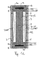
- Figure 1a shows a sectional view (through the central, longitudinal axis of the shown device) of a magnetorheological force transmission device according to the present invention, which constitutes a shock absorber.
- Figure 1b shows a cross-section through the shown device along the direction A-A in figure 1a , i.e. perpendicular to the axis R.
- the shown damper comprises two piston elements: A first piston element 1a, essentially formed in form of a cylinder, which is inserted or nested in a second piston element 1b, which is formed as a hollow cylinder in which the first piston element 1a can be introduced along the longitudinal symmetry axis R of the shown device.
- both pistons are adapted to be moved one relative to the other in a translational manner along a common line, wherein said line is arranged essentially in parallel to the common longitudinal axis R of the two pistons or equals this common axis.
- the part 1a is thus slideably movable within the part 1b.
- Both parts 1a and 1b are essentially formed by a ferromagnetic material, in this case iron.
- the inner piston 1a comprises an outer yoke part 1a-y1 and the inner section (i.e. the section which is arranged in the area of the central axis R and around the central axis R within the outer yoke part 1a-y1) is formed as an inner yoke part 1a-y2.
- the gap between the part 1a and the part 1b comprises in an upper portion and in a lower portion ring-shaped sealing elements 6 of which the diameter corresponds to the outer diameter of the inner piston 1a.
- the parts 1a and 1b are inserted into one another in a sealed condition.
- the inner piston 1a is moved relative to the outer piston 1b along the line R in a manner which is later described in more detail (i.e. in a manner dependent upon the stiffness of the magnetorheological material 2MRF).
- the inner piston 1a Seen along the central axis R, the inner piston 1a contains three different sections or areas, in which three different separated magnetic circuits are formed (see below):
- a magnetic-field-balancing insert 5 (here formed of aluminum and shaped in form of a flat disk which is arranged perpendicular to the axis R).
- the coil of an electromagnet 3 is disposed on the outer circumference of said disk 5 .
- the inner radius of the hollow-cylinder-shaped electromagnet 3 (the symmetry axis of the hollow cylinder corresponds to the axis R), therefore equals the outer radius of the disk of the magnetic-field-balancing insert 5 so that the inner yoke part 1a-y2 is completely separated by the disk 5 into an upper part and into a lower part along the axis R in a symmetric arrangement.
- a ring-shaped magnetic-field-balancing insert (not shown) can be provided which completely separates the outer yoke part 1a-y1 into symmetric parts along the axis R. Also such an arrangement provides a complete separation in such a manner that each magnetic flux line of the second magnetic circuit M2 has to pass through a part of the magnetic-field-balancing insert.
- at least one of the magnetic-field-balancing inserts 5 is either arranged centrically, preferably essentially in the shape of a disk, on said line R or concentrically, preferably essentially in the shape of a hollow-cylinder, a torus or a circular ring, around said line.
- Each of the permanent magnets 4a and 4b is surrounded by one non-magnetic insert formed out of aluminum (magnetic isolators 7a and 7b).
- Each of the magnetic isolators 7a and 7b is formed as a flat ring, whose inner diameter corresponds to the outer diameter of the corresponding permanent magnet 4a and 4b.
- Each permanent magnet 4a, 4b is arranged at the same position (seen along the axis R) as its corresponding magnetic isolator 7a, 7b.
- the permanent magnets 4a, 4b are made of a hard-magnetic material like NdFeB. Both permanent magnets 4a, 4b are arranged thus that their magnetic field lines flow in parallel (i.e. identical arrangement of their respective north-south orientation (NS)).
- the shown inner piston 1a is provided with an MRF gap 2 which extends around the whole circumference of the inner piston 1a at a radius distance from the axis R which approximately corresponds to the outer diameter of the magnetic isolators 7a and 7b or the outer diameter of the hollow cylinder-shaped electromagnet 3.
- the MRF gap 2 extends nearly along the whole length of the inner piston 1a (seen in direction of the axis R) except for the upper end part and the lower end part of the inner piston 1a (these are the parts which extend, seen from the central point P of the symmetric system arrangement, above the elements 4a/7a and below the elements 4b/7b).
- the piston 1a is provided, see figure 1b , with a plurality of outlets 2a, 2b, 2c, ... connected to the MRF gap 2 or being part of the latter, respectively, and being arranged circumferentially at a distance from the axis R, which approximately corresponds to the distance of the MRF gap 2 from said axis R.
- the outlets 2a, 2b, 2c, ... and the MRF gap 2 are arranged along the axis R in such a manner that a magnetorheological fluid 2MRF can flow through the channels 2, 2a, 2b, 2c, ... along the axis R.
- the MRF gap 2 is arranged essentially in parallel to the common longitudinal axis of the two pistons.
- the magnetic isolators (7a, 7b) are used to increase the field due to the permanent magnets (pm) in the 2U/2L valve. They are preferably as large as possible to improve the generation of the field by permanent magnets (pm) and to avoid/reduce pm field short circuit. To even improve this function, enlarged inserts 7a, 7b could be used. In the opposite of magnetic-field-balancing insert 5, assuming the 2U/2L valve length is the same, the coil field is not modified by their design.
- magnetic balancing insert 5 is a matter of compromise and realizes the idea of the invention. For a given number of Ampere-turns in the coil,
- insert 5 allows balancing coil field vs. pm field in the valves. For this reason, insert 5 has not the same role as 7a and 7b.
- the magnetorheological force transmission device shown provides a mirror-symmetric arrangement of its elements seen along the axis R or a plane through the point P perpendicular to said axis R, respectively, and a rotational-symmetric arrangement around the axis R (rotational-symmetric except for elements 2a, 2b, 2c, ).
- the arrangement of the upper permanent magnet 4a together with its corresponding magnetic isolator 7a provides together with the corresponding upper active MRF gap part 2U a first, upper MRF valve whereas the lower arrangement of the elements 4b, 7b together with the corresponding lower, active part 2L of the MRF gap provides a second, lower MRF valve.
- MRF flows through the inlets/outlets 2a, 2b, 2c, ... through both of the MRF valves and from the upper side to the lower side or from the lower side to the upper side of the inner piston 1a, respectively, thus streaming through said piston.
- the inlets/outlets are nearly free of a magnetic field (the flux of the MRF stream is, by increasing the diameter of the MRF gap 2 along the extension of the electromagnet 3, expanded in order to realize a higher switching factor between magnetorheological and fluid hydraulic pressure loss (ratio of the pressure losses with and without magnetic field, respectively)).
- the inner piston 1a is sealed with standard sealings 6 against the outer hull so that no bypass gap results in the present case.
- the two permanent magnets 4a and 4b comprise the same magnetic orientation N-S. Otherwise, when using the electromagnet (by a current flow) the magnetic flux in one active MRF gap (e.g. 2U) would be increased whereas the magnetic flux in the other active MRF gap (e.g. 2L) would be decreased so that essentially no change of the fluid resistance would result for the MRF 2MRF.
- one active MRF gap e.g. 2U
- the magnetic flux in the other active MRF gap e.g. 2L
- the permanent magnets As shown, it is possible to realize a basic shear-stress of the MRF without any electric energy input due to the electromagnet. By using the electromagnet it is then possible to attenuate the magnetic field of the permanent magnets down to nearly zero thus that in an extreme case only the fluid hydraulic features of the MRF without magnetic field are relevant. On the other hand, it is possible to increase the field of the permanent magnets thus that very high shear-stress values can be attained. Due to the basic shear-stress set with help of the permanent magnets, a fail-safe behavior of the shown device can be secured.
- Figure 1c shows the first magnetic circuit (magnetic flux lines M1) of the present system which comprises the permanent magnet 4a, the magnetic isolator 7a, the part of the MRF gap 2 corresponding to the upper part magnetic valve 2U and the parts of the inner yoke part 1a-y2 and of the outer yoke part 1a-y1 as well as the part of the upper lid of the inner piston 1a, which surround said elements 4a, 7a.
- the third magnetic circuit (magnetic flux lines M3) which comprises the corresponding parts at the lower end of the piston 1a: Elements 4b and 7b as well as the parts of the elements 1a-y2, 1a-y1 and of the lower lid of the piston 1a which surround the elements 4a, 7b.
- both permanent magnets 4a, 4b close their magnetic flux lines exclusively through the MRF gap 2 (in the area of the active parts 2U, 2L).
- the inner yoke part 1a-y2 is interrupted with the magnetic-field-balancing insert 5.
- figure 1d also shows the central magnetic circuit, the second magnetic circuit (magnetic field flux lines M2) which comprises the electromagnet 3, the magnetic-field-balancing insert 5 and those parts of the inner yoke part 1a-y2, of the outer yoke part 1a-y1 and of the MRF gap 2 surrounding these elements 5 and 3.
- the current flowing through the electromagnet coil is selected thus that the electromagnet 3 is operated in an increasing manner with respect to the two permanent magnets, which means that the magnetic fields generated by the permanent magnets and by the electromagnet are increasing each other in the MRF valves.
- the direction of the current flowing through the electromagnet 3 is selected thus that the electromagnet 3 is operated in an attenuating manner with respect to the two permanent magnets 4a, 4b.
- the magnetic flux of the electromagnet presses the flux of the permanent magnets out of the MRF valves and consequently the magnetic flux of the system is closed within one magnetic circuit (magnetic flux lines MA) over the elements 3, 4a, 4b, 5, 7a, 7b over the outer yoke.
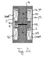
- FIGS 2a to 2d show a second example of the present invention. Therein, only an inner piston 1a of the arrangement is shown.
- the inner piston 1a with all the elements it comprises is generally arranged, formed and built as is the inner piston of the first embodiment (compare description of the first embodiment) so that only the differences are described in the following sections:
- the first and the second permanent magnets 4a, 4b of the first embodiment are replaced by electromagnets 3a and 3b and, instead of providing on the outer periphery of the magnets magnetic isolators, magnetic-field-balancing inserts 5a, 5b, the non-magnetic inserts are provided extending along and over the whole diameter of the inner periphery of the electromagnets 3a, 3b.
- either the one permanent magnet can be sandwiched in-between the two electromagnets or the one electromagnet can be sandwiched in-between the two permanent magnets.
- the two MRF valves 2U and 2L are formed in the area of the central section along the axis R of the shown arrangement.
- the second magnetic circuit is generated with help of the permanent magnet (see figure 2b ) with the magnetic flux lines M2
- the first and the third magnetic circuits are generated by the first and the second electromagnet 3a, 3b together with their corresponding magnetic-field-balancing inserts, respectively (see figure 2c ).
- Figure 2b shows the operation mode when only the permanent magnet is operated.
- the permanent magnet closes its magnetic flux lines over the two MRF valves arranged in the center of the arrangement.
- the two magnetic-field-balancing inserts 5a and 5b arranged in the center of the two electromagnets 3a and 3b prevent the magnetic flux of the permanent magnet to be closed over the complete outer yoke part 1a-y1.
- Figure 2c shows the operation mode when the current flowing through the electromagnets 3a and 3b is selected thus (see description with respect to embodiment 1) that the magnetic fields of the permanent magnet and the electromagnets are increased within the MRF gap 2 (operation mode of increasing the magnetic flux within the MRF gap 2). Both of the coils of the electromagnets 3 then have to have the same polarity, only then both MRF valves are passed by the magnetic fluxes in the direction of an increase.
- Figure 2d shows the second embodiment in the operation mode of the magnetic field attenuation:
- the polarity (i.e. the current direction) of both of the electromagnets 3a and 3b is now reversed, consequently, the magnetic flux is pressed out of the region of the MRF valves and so the magnetic flux of the whole arrangement closes over the whole extension of the outer yoke part 1a-y1 (e.g. comprises, as within the first embodiment, all elements 3a, 3b, 4, 5a, 5b, 7, see the magnetic flux lines MA).
- one essential gist of the present invention is that within the magnetic circuit system of the yoke circuit of the arrangement shown, magnetic-field-weakening inserts, especially magnetic-field-balancing inserts and/or magnetic isolators, are used.
- the corresponding insert used as the interruption of the central yoke part provides the following in the present invention: As both of the permanent magnets in embodiment 1 have the same magnetic orientation, these two permanent magnets would provide a magnetic short-circuit over the yoke without guiding the magnetic flux through the MRF gap 2 without providing said magnetic-field-weakening insert.
- the thus realized interruption consequently adjusts the "basic flux density" which the permanent magnets generate without any current of the coil of the electromagnet.
- the magnetic-field-balancing insert comprises the same area as the area superposed within the inner or the outer yoke part of the electromagnet, i.e. the flux of the magnetic field lines of the electromagnet, has to pass completely through said magnetic-field-weakening insert.
- each permanent magnet penetrates only the area of one MRF valve. This also leads to the increased magnetic field strength in summation.
- Also a large increase of the magnetic field within the MRF valves is possible.
- each element which generates a magnetic field comprises at least one magnetic-field-balancing insert and/or one magnetic isolator.
- the insert of the electromagnet (embodiment 1) is arranged thus that each magnetic field line of the electromagnet passes through this insert.
- the inserts of the two outer permanent magnets (embodiment 1) are arranged thus that each magnetic field line of a corresponding permanent magnet completely surrounds said insert in a closed manner.
Priority Applications (2)
| Application Number | Priority Date | Filing Date | Title |
|---|---|---|---|
| EP07023063A EP2065614A1 (fr) | 2007-11-28 | 2007-11-28 | Dispositif magnétorhéologique de transmission de forces |
| US12/276,883 US8205728B2 (en) | 2007-11-28 | 2008-11-24 | Magnetorheological force transmission device |
Applications Claiming Priority (1)
| Application Number | Priority Date | Filing Date | Title |
|---|---|---|---|
| EP07023063A EP2065614A1 (fr) | 2007-11-28 | 2007-11-28 | Dispositif magnétorhéologique de transmission de forces |
Publications (1)
| Publication Number | Publication Date |
|---|---|
| EP2065614A1 true EP2065614A1 (fr) | 2009-06-03 |
Family
ID=39313258
Family Applications (1)
| Application Number | Title | Priority Date | Filing Date |
|---|---|---|---|
| EP07023063A Withdrawn EP2065614A1 (fr) | 2007-11-28 | 2007-11-28 | Dispositif magnétorhéologique de transmission de forces |
Country Status (2)
| Country | Link |
|---|---|
| US (1) | US8205728B2 (fr) |
| EP (1) | EP2065614A1 (fr) |
Cited By (12)
| Publication number | Priority date | Publication date | Assignee | Title |
|---|---|---|---|---|
| WO2010089082A1 (fr) * | 2009-02-03 | 2010-08-12 | Fraunhofer-Gesellschaft zur Förderung der angewandten Forschung e.V. | Dispositif magnétorhéologique commutable pour la transmission de couple ou de force, son utilisation et procédé magnétorhéologique de transmission de couple ou de force |
| WO2018233971A1 (fr) | 2017-06-21 | 2018-12-27 | Zf Friedrichshafen Ag | Dispositif de commande rotatif destiné à un véhicule |
| DE102017210438A1 (de) | 2017-06-21 | 2018-12-27 | Zf Friedrichshafen Ag | Drehsteuereinrichtung für ein Fahrzeug |
| DE102017210436A1 (de) | 2017-06-21 | 2018-12-27 | Zf Friedrichshafen Ag | Drehsteuereinrichtung |
| DE102017210442A1 (de) | 2017-06-21 | 2018-12-27 | Zf Friedrichshafen Ag | Dehsteuervorrichtung |
| WO2018233972A1 (fr) | 2017-06-21 | 2018-12-27 | Zf Friedrichshafen Ag | Dispositif de commande rotatif |
| DE102018222235A1 (de) | 2018-12-19 | 2020-06-25 | Zf Friedrichshafen Ag | Drehsteuervorrichtung |
| WO2021043648A1 (fr) * | 2019-09-06 | 2021-03-11 | Zf Friedrichshafen Ag | Dispositif de commande pour un véhicule et procédé pour régler une caractérstique de fonctionnement d'un dispositif de commande |
| WO2021048264A1 (fr) | 2019-09-12 | 2021-03-18 | Zf Friedrichshafen Ag | Dispositif de commande rotatif pour commander la direction |
| WO2021048254A1 (fr) | 2019-09-12 | 2021-03-18 | Zf Friedrichshafen Ag | Dispositif de commande rotatif pour commander la direction |
| EP3393850B1 (fr) * | 2015-12-21 | 2022-02-16 | LORD Corporation | Dispositifs, systèmes et procédés d'amortissement de siège perfectionnés |
| DE102021213261A1 (de) | 2021-11-25 | 2023-05-25 | Zf Friedrichshafen Ag | Magnetorheologischer Aktor und Drehsteuervorrichtung |
Families Citing this family (21)
| Publication number | Priority date | Publication date | Assignee | Title |
|---|---|---|---|---|
| US7823708B2 (en) * | 2005-11-02 | 2010-11-02 | Ford Global Technologies, Llc | Magnetorheological damping device for reduction or elimination of vibration in steering systems |
| DE102009060525B4 (de) * | 2009-12-23 | 2012-05-03 | Inventus Engineering Gmbh | Ventil für eine magnetorheologische Flüssigkeit |
| CN101915283B (zh) * | 2010-08-06 | 2011-12-07 | 浙江大学 | 一种磁流变复合阻尼控制方法与装置 |
| US9078734B2 (en) * | 2011-09-06 | 2015-07-14 | össur hf | Prosthetic and orthotic devices having magnetorheological elastomer spring with controllable stiffness |
| US8303110B1 (en) | 2011-09-11 | 2012-11-06 | Google Inc. | Nose pads for a wearable device having an electrically-controllable hardness |
| KR101724747B1 (ko) * | 2011-11-23 | 2017-04-10 | 현대자동차주식회사 | Mre를 이용한 가변형 디퍼런셜 마운트 장치 |
| US9109654B2 (en) * | 2012-06-12 | 2015-08-18 | Inno Vital Systems, Inc. | Failsafe magnetorheological (MR) energy absorber |
| US20140028117A1 (en) * | 2012-07-27 | 2014-01-30 | Vytautas Bucinskas | Chaotic vibration energy harvester and method for controlling same |
| US20140027217A1 (en) * | 2012-07-27 | 2014-01-30 | Vytautas Bucinskas | Energy harvesting shock absorber and method for controlling same |
| KR101886711B1 (ko) * | 2014-10-02 | 2018-08-09 | 주식회사 씨케이머티리얼즈랩 | 자성 촉각 제공 장치 |
| CN104763825B (zh) * | 2015-04-19 | 2017-07-04 | 华东交通大学 | 一种采用永久磁铁和双线圈进行复合控制的磁流变阀 |
| JP6405336B2 (ja) * | 2016-05-11 | 2018-10-17 | 本田技研工業株式会社 | 能動型振動制御装置 |
| JP6368735B2 (ja) * | 2016-05-11 | 2018-08-01 | 本田技研工業株式会社 | 能動型振動制御装置 |
| CN106763445B (zh) * | 2017-01-06 | 2017-11-03 | 天津大学 | 一种智能材料减振器的变阻尼变刚度控制方法 |
| CN106594157B (zh) * | 2017-01-06 | 2017-11-03 | 天津大学 | 一种基于智能材料的变刚度变阻尼减振器 |
| CN106838062B (zh) * | 2017-03-30 | 2018-11-27 | 东北大学 | 一种y型制动盘磁流变制动器 |
| CN107395188B (zh) * | 2017-07-12 | 2020-01-17 | 华南农业大学 | 基于磁流变液的无人机遥控触觉按钮及控制方法 |
| US10598248B2 (en) | 2017-11-01 | 2020-03-24 | Simon Fraser University | Smart fluid damper |
| JP2022533859A (ja) | 2019-05-29 | 2022-07-26 | ビッグ カイザー プレツィヅィオンスヴェルクツォイク アーゲー | 変位可能な刃具キャリアを締め付けるための機構を備えたボーリングヘッド |
| CN110319150B (zh) * | 2019-06-28 | 2020-12-04 | 南京理工大学 | 用于旋转振动的磁流变弹性体-磁流变液复合减振器 |
| CN110388404A (zh) * | 2019-08-27 | 2019-10-29 | 华东交通大学 | 一种剪切型磁流变液阻尼器 |
Citations (7)
| Publication number | Priority date | Publication date | Assignee | Title |
|---|---|---|---|---|
| GB675352A (en) * | 1949-12-02 | 1952-07-09 | British Thomson Houston Co Ltd | Improvements in and relating to brakes, clutches and the like |
| JPS63259235A (ja) * | 1987-04-16 | 1988-10-26 | Nkk Corp | 磁性流体ダンパ装置 |
| US5632361A (en) * | 1994-09-16 | 1997-05-27 | Fichtel & Sachs Ag | Vibration damper, in particular for motor vehicles |
| US6427813B1 (en) * | 1997-08-04 | 2002-08-06 | Lord Corporation | Magnetorheological fluid devices exhibiting settling stability |
| DE10143980A1 (de) | 2001-09-07 | 2003-03-27 | Bosch Rexroth Ag | Magneto-Rheologischer Dämpfer |
| EP1270988B1 (fr) | 2001-06-19 | 2005-07-27 | Delphi Technologies, Inc. | Amortisseur à fluide magnétorhéologique |
| US20060016649A1 (en) * | 2004-04-02 | 2006-01-26 | University Of Nevada | Controllable magneto-rheological fluid devices for motion-damping |
Family Cites Families (9)
| Publication number | Priority date | Publication date | Assignee | Title |
|---|---|---|---|---|
| US5263558A (en) * | 1990-10-20 | 1993-11-23 | Atsugi Unisia Corporation | Electromagnetic strut assembly |
| GB2253677B (en) * | 1991-02-14 | 1994-09-28 | Atsugi Unisia Corp | Electromagnetic suspension device |
| US5947238A (en) * | 1997-03-05 | 1999-09-07 | Lord Corporation | Passive magnetorheological fluid device with excursion dependent characteristic |
| US6390252B1 (en) * | 1999-09-13 | 2002-05-21 | Delphi Technologies, Inc. | Magnetorheological fluid damper with optimum damping |
| US6328369B1 (en) * | 1999-12-28 | 2001-12-11 | Yugenkaisha Paramount Corporation | Automobile |
| US6722480B2 (en) * | 2002-05-07 | 2004-04-20 | Lord Corporation | Magnetically actuated motion control device |
| ATE378206T1 (de) * | 2002-08-21 | 2007-11-15 | Delphi Tech Inc | Kolbendämpfungsanordnung und staubrohrunteranordung mit geschwindigkeitssensor |
| WO2007091399A1 (fr) * | 2006-02-09 | 2007-08-16 | Central Research Institute Of Electric Power Industry | Amortisseur à fluide |
| US20070193839A1 (en) * | 2006-02-23 | 2007-08-23 | Honda Motor Co., Ltd. | Variable attenuation power damper |
-
2007
- 2007-11-28 EP EP07023063A patent/EP2065614A1/fr not_active Withdrawn
-
2008
- 2008-11-24 US US12/276,883 patent/US8205728B2/en not_active Expired - Fee Related
Patent Citations (7)
| Publication number | Priority date | Publication date | Assignee | Title |
|---|---|---|---|---|
| GB675352A (en) * | 1949-12-02 | 1952-07-09 | British Thomson Houston Co Ltd | Improvements in and relating to brakes, clutches and the like |
| JPS63259235A (ja) * | 1987-04-16 | 1988-10-26 | Nkk Corp | 磁性流体ダンパ装置 |
| US5632361A (en) * | 1994-09-16 | 1997-05-27 | Fichtel & Sachs Ag | Vibration damper, in particular for motor vehicles |
| US6427813B1 (en) * | 1997-08-04 | 2002-08-06 | Lord Corporation | Magnetorheological fluid devices exhibiting settling stability |
| EP1270988B1 (fr) | 2001-06-19 | 2005-07-27 | Delphi Technologies, Inc. | Amortisseur à fluide magnétorhéologique |
| DE10143980A1 (de) | 2001-09-07 | 2003-03-27 | Bosch Rexroth Ag | Magneto-Rheologischer Dämpfer |
| US20060016649A1 (en) * | 2004-04-02 | 2006-01-26 | University Of Nevada | Controllable magneto-rheological fluid devices for motion-damping |
Cited By (19)
| Publication number | Priority date | Publication date | Assignee | Title |
|---|---|---|---|---|
| WO2010089082A1 (fr) * | 2009-02-03 | 2010-08-12 | Fraunhofer-Gesellschaft zur Förderung der angewandten Forschung e.V. | Dispositif magnétorhéologique commutable pour la transmission de couple ou de force, son utilisation et procédé magnétorhéologique de transmission de couple ou de force |
| EP3393850B1 (fr) * | 2015-12-21 | 2022-02-16 | LORD Corporation | Dispositifs, systèmes et procédés d'amortissement de siège perfectionnés |
| WO2018233972A1 (fr) | 2017-06-21 | 2018-12-27 | Zf Friedrichshafen Ag | Dispositif de commande rotatif |
| WO2018233971A1 (fr) | 2017-06-21 | 2018-12-27 | Zf Friedrichshafen Ag | Dispositif de commande rotatif destiné à un véhicule |
| DE102017210436A1 (de) | 2017-06-21 | 2018-12-27 | Zf Friedrichshafen Ag | Drehsteuereinrichtung |
| WO2018233969A1 (fr) | 2017-06-21 | 2018-12-27 | Zf Friedrichshafen Ag | Dispositif de commande de rotation |
| DE102017210437A1 (de) | 2017-06-21 | 2018-12-27 | Zf Friedrichshafen Ag | Drehsteuereinrichtung für ein Fahrzeug |
| DE102017210442A1 (de) | 2017-06-21 | 2018-12-27 | Zf Friedrichshafen Ag | Dehsteuervorrichtung |
| DE102017210438A1 (de) | 2017-06-21 | 2018-12-27 | Zf Friedrichshafen Ag | Drehsteuereinrichtung für ein Fahrzeug |
| DE102017210439A1 (de) | 2017-06-21 | 2018-12-27 | Zf Friedrichshafen Ag | Drehsteuervorrichtung |
| WO2018233973A1 (fr) | 2017-06-21 | 2018-12-27 | Zf Friedrichshafen Ag | Dispositif de commande rotatif |
| WO2018233970A1 (fr) | 2017-06-21 | 2018-12-27 | Zf Friedrichshafen Ag | Dispositif de commande rotatif pour véhicule |
| DE102018222235A1 (de) | 2018-12-19 | 2020-06-25 | Zf Friedrichshafen Ag | Drehsteuervorrichtung |
| WO2020127419A1 (fr) | 2018-12-19 | 2020-06-25 | Zf Friedrichshafen Ag | Dispositif de commande de rotation |
| WO2021043648A1 (fr) * | 2019-09-06 | 2021-03-11 | Zf Friedrichshafen Ag | Dispositif de commande pour un véhicule et procédé pour régler une caractérstique de fonctionnement d'un dispositif de commande |
| WO2021048264A1 (fr) | 2019-09-12 | 2021-03-18 | Zf Friedrichshafen Ag | Dispositif de commande rotatif pour commander la direction |
| WO2021048254A1 (fr) | 2019-09-12 | 2021-03-18 | Zf Friedrichshafen Ag | Dispositif de commande rotatif pour commander la direction |
| DE102021213261A1 (de) | 2021-11-25 | 2023-05-25 | Zf Friedrichshafen Ag | Magnetorheologischer Aktor und Drehsteuervorrichtung |
| WO2023094345A1 (fr) | 2021-11-25 | 2023-06-01 | Zf Friedrichshafen Ag | Actionneur magnétorhéologique et dispositif de commande de rotation |
Also Published As
| Publication number | Publication date |
|---|---|
| US8205728B2 (en) | 2012-06-26 |
| US20090133976A1 (en) | 2009-05-28 |
Similar Documents
| Publication | Publication Date | Title |
|---|---|---|
| US8205728B2 (en) | Magnetorheological force transmission device | |
| US6279701B1 (en) | Magnetorheological fluid damper with multiple annular flow gaps | |
| US20120085613A1 (en) | Switchable magnetorheological torque or force transmission device, the use thereof, and magnetorheological torque or force transmission method | |
| KR101727767B1 (ko) | 자동차 쇽 업소버 | |
| KR101557909B1 (ko) | 자기 유변 댐핑 조립체 | |
| EP2504606B1 (fr) | Ensemble amortisseur à solénoïde bistable | |
| CA2637511C (fr) | Amortisseur a fluide | |
| US6874603B2 (en) | Magnetorheological piston and damper assembly | |
| US20100193304A1 (en) | Damping device with field-controllable fluid | |
| WO1999027273A2 (fr) | Valve ajustable et amortisseurs de vibrations utilisant cette valve | |
| JPH01312240A (ja) | 半能動ダンパピストン弁組立体 | |
| US8985149B2 (en) | Adjustable valve with a transition region | |
| EP1433974A1 (fr) | Ensemble amortisseur magnétorhéologique et piston | |
| JP2005291338A (ja) | ダンパ | |
| US11815142B2 (en) | Magnetorheological brake with high torque and fast response | |
| EP1270989B1 (fr) | Amortisseur à fluide magnétorhéologique avec de multiples passages annulaires | |
| CN102606790B (zh) | 特别是用于减振器的可调节阻尼阀的可电磁操纵的致动器 | |
| JP2005291284A (ja) | ダンパ | |
| CN215673335U (zh) | 主动型防振装置 | |
| EP2143971A2 (fr) | Assemblage de vanne à piston et amortissement l'incluant | |
| CN100348885C (zh) | 一种复合结构磁流变液半主动减振器 | |
| KR101907583B1 (ko) | 자기 유동성 유체를 이용한 가변 강성 구동기 및 이를 적용한 역감 전달 시스템 | |
| CN215487376U (zh) | 主动型防振装置 | |
| RU2204067C2 (ru) | Гидравлический амортизатор | |
| CN113074208B (zh) | 一种复合式磁流变减振装置 |
Legal Events
| Date | Code | Title | Description |
|---|---|---|---|
| PUAI | Public reference made under article 153(3) epc to a published international application that has entered the european phase |
Free format text: ORIGINAL CODE: 0009012 |
|
| AK | Designated contracting states |
Kind code of ref document: A1 Designated state(s): AT BE BG CH CY CZ DE DK EE ES FI FR GB GR HU IE IS IT LI LT LU LV MC MT NL PL PT RO SE SI SK TR |
|
| AX | Request for extension of the european patent |
Extension state: AL BA HR MK RS |
|
| 17P | Request for examination filed |
Effective date: 20090708 |
|
| 17Q | First examination report despatched |
Effective date: 20090824 |
|
| AKX | Designation fees paid |
Designated state(s): AT BE BG CH CY CZ DE DK EE ES FI FR GB GR HU IE IS IT LI LT LU LV MC MT NL PL PT RO SE SI SK TR |
|
| STAA | Information on the status of an ep patent application or granted ep patent |
Free format text: STATUS: THE APPLICATION IS DEEMED TO BE WITHDRAWN |
|
| 18D | Application deemed to be withdrawn |
Effective date: 20140603 |