EP2065320B2 - Appareil pour débrouiller et aligner des préformes - Google Patents
Appareil pour débrouiller et aligner des préformes Download PDFInfo
- Publication number
- EP2065320B2 EP2065320B2 EP07022926.5A EP07022926A EP2065320B2 EP 2065320 B2 EP2065320 B2 EP 2065320B2 EP 07022926 A EP07022926 A EP 07022926A EP 2065320 B2 EP2065320 B2 EP 2065320B2
- Authority
- EP
- European Patent Office
- Prior art keywords
- preforms
- sidewalls
- preform
- rollers
- correctly oriented
- Prior art date
- Legal status (The legal status is an assumption and is not a legal conclusion. Google has not performed a legal analysis and makes no representation as to the accuracy of the status listed.)
- Active
Links
- 238000011144 upstream manufacturing Methods 0.000 claims description 15
- 238000000071 blow moulding Methods 0.000 claims description 10
- 238000004519 manufacturing process Methods 0.000 claims description 6
- 239000002991 molded plastic Substances 0.000 claims description 3
- 230000005484 gravity Effects 0.000 description 6
- 239000007924 injection Substances 0.000 description 5
- 230000000694 effects Effects 0.000 description 4
- 239000004033 plastic Substances 0.000 description 4
- 238000002347 injection Methods 0.000 description 3
- 238000000034 method Methods 0.000 description 3
- 238000004064 recycling Methods 0.000 description 3
- 230000002301 combined effect Effects 0.000 description 2
- 238000001746 injection moulding Methods 0.000 description 2
- 238000000465 moulding Methods 0.000 description 2
- 238000007664 blowing Methods 0.000 description 1
- 230000007257 malfunction Effects 0.000 description 1
- 238000004806 packaging method and process Methods 0.000 description 1
- 239000000243 solution Substances 0.000 description 1
Images


Classifications
-
- B—PERFORMING OPERATIONS; TRANSPORTING
- B65—CONVEYING; PACKING; STORING; HANDLING THIN OR FILAMENTARY MATERIAL
- B65G—TRANSPORT OR STORAGE DEVICES, e.g. CONVEYORS FOR LOADING OR TIPPING, SHOP CONVEYOR SYSTEMS OR PNEUMATIC TUBE CONVEYORS
- B65G47/00—Article or material-handling devices associated with conveyors; Methods employing such devices
- B65G47/22—Devices influencing the relative position or the attitude of articles during transit by conveyors
- B65G47/24—Devices influencing the relative position or the attitude of articles during transit by conveyors orientating the articles
- B65G47/256—Devices influencing the relative position or the attitude of articles during transit by conveyors orientating the articles removing incorrectly orientated articles
-
- B—PERFORMING OPERATIONS; TRANSPORTING
- B29—WORKING OF PLASTICS; WORKING OF SUBSTANCES IN A PLASTIC STATE IN GENERAL
- B29C—SHAPING OR JOINING OF PLASTICS; SHAPING OF MATERIAL IN A PLASTIC STATE, NOT OTHERWISE PROVIDED FOR; AFTER-TREATMENT OF THE SHAPED PRODUCTS, e.g. REPAIRING
- B29C49/00—Blow-moulding, i.e. blowing a preform or parison to a desired shape within a mould; Apparatus therefor
- B29C49/42—Component parts, details or accessories; Auxiliary operations
- B29C49/4205—Handling means, e.g. transfer, loading or discharging means
-
- B—PERFORMING OPERATIONS; TRANSPORTING
- B65—CONVEYING; PACKING; STORING; HANDLING THIN OR FILAMENTARY MATERIAL
- B65G—TRANSPORT OR STORAGE DEVICES, e.g. CONVEYORS FOR LOADING OR TIPPING, SHOP CONVEYOR SYSTEMS OR PNEUMATIC TUBE CONVEYORS
- B65G11/00—Chutes
- B65G11/16—Interior surfaces; Linings
- B65G11/166—Interior surfaces; Linings for bulk
-
- B—PERFORMING OPERATIONS; TRANSPORTING
- B29—WORKING OF PLASTICS; WORKING OF SUBSTANCES IN A PLASTIC STATE IN GENERAL
- B29C—SHAPING OR JOINING OF PLASTICS; SHAPING OF MATERIAL IN A PLASTIC STATE, NOT OTHERWISE PROVIDED FOR; AFTER-TREATMENT OF THE SHAPED PRODUCTS, e.g. REPAIRING
- B29C2949/00—Indexing scheme relating to blow-moulding
- B29C2949/07—Preforms or parisons characterised by their configuration
- B29C2949/0715—Preforms or parisons characterised by their configuration the preform having one end closed
-
- B—PERFORMING OPERATIONS; TRANSPORTING
- B29—WORKING OF PLASTICS; WORKING OF SUBSTANCES IN A PLASTIC STATE IN GENERAL
- B29C—SHAPING OR JOINING OF PLASTICS; SHAPING OF MATERIAL IN A PLASTIC STATE, NOT OTHERWISE PROVIDED FOR; AFTER-TREATMENT OF THE SHAPED PRODUCTS, e.g. REPAIRING
- B29C49/00—Blow-moulding, i.e. blowing a preform or parison to a desired shape within a mould; Apparatus therefor
- B29C49/02—Combined blow-moulding and manufacture of the preform or the parison
- B29C49/06—Injection blow-moulding
-
- B—PERFORMING OPERATIONS; TRANSPORTING
- B29—WORKING OF PLASTICS; WORKING OF SUBSTANCES IN A PLASTIC STATE IN GENERAL
- B29C—SHAPING OR JOINING OF PLASTICS; SHAPING OF MATERIAL IN A PLASTIC STATE, NOT OTHERWISE PROVIDED FOR; AFTER-TREATMENT OF THE SHAPED PRODUCTS, e.g. REPAIRING
- B29C49/00—Blow-moulding, i.e. blowing a preform or parison to a desired shape within a mould; Apparatus therefor
- B29C49/42—Component parts, details or accessories; Auxiliary operations
- B29C49/4205—Handling means, e.g. transfer, loading or discharging means
- B29C49/42051—Means for stripping, aligning or de-stacking
- B29C49/42057—Aligning disorderly arranged preforms, e.g. delivered disorderly
-
- B—PERFORMING OPERATIONS; TRANSPORTING
- B29—WORKING OF PLASTICS; WORKING OF SUBSTANCES IN A PLASTIC STATE IN GENERAL
- B29C—SHAPING OR JOINING OF PLASTICS; SHAPING OF MATERIAL IN A PLASTIC STATE, NOT OTHERWISE PROVIDED FOR; AFTER-TREATMENT OF THE SHAPED PRODUCTS, e.g. REPAIRING
- B29C49/00—Blow-moulding, i.e. blowing a preform or parison to a desired shape within a mould; Apparatus therefor
- B29C49/42—Component parts, details or accessories; Auxiliary operations
- B29C49/4205—Handling means, e.g. transfer, loading or discharging means
- B29C49/42051—Means for stripping, aligning or de-stacking
- B29C49/42059—Aligning of preforms getting stuck, unaligned or stacked during transport
Definitions
- the present invention relates to preforms and an improved apparatus for unscrambling and aligning preforms according to the preamble of the appended claim 1.
- This apparatus is used, for example, for feeding preforms to a machine, like a blow-moulding machine for making plastic containers.
- the present invention also relates to a feed system comprising said preforms and apparatus, to the use of said preforms and apparatus and to a system for manufacturing blow-moulded plastic containers comprising said preforms and apparatus.
- plastic preforms are moulded by injection in an injection machine.
- a preform has a substantially tubular body that is closed at one bottom end and is opened at the other upper end.
- a preform also comprises a neck support ring in its upper part, close to its opened mouth.
- the preforms are fed to a blow-moulding machine that is used for making bi-axially oriented containers by stretching and blowing each preform in a mould.
- the injection machine for manufacturing the preforms and the blowing-moulding machine for manufacturing the containers from the preforms are two independent machines.
- a feeding system of the type illustrated in FIG.1 is used generally for feeding the blowing-moulding machine with aligned and correctly oriented preforms. More generally, such a feeding system can be used for feeding any machine with aligned and correctly oriented preforms.
- Such a feeding system comprises an apparatus for unscrambling and aligning the preforms, and generally referred as "unscrambler".
- An unscrambler generally comprises two rotary alignment rollers which are inclined to the horizontal and which are substantially parallel to each other. These two rollers are separated from each others in such a way to leave a space along and between the rollers for the body of the preforms. The distance between the two rollers is however sufficiently small for enabling the two rollers to retain the preforms by their neck support ring.
- the preforms fall under the effect of gravity onto the alignment rollers which are driven in rotation in opposite directions. Under the combined effect of gravity and rotation of the alignment rollers, the preforms tend to move and to be oriented between the rollers in an upright position. Correctly oriented preforms are thus aligned and supported on the two rollers by their neck support ring, while the body of the preforms hangs down between the rollers.
- the aligned and correctly oriented preforms slide under the effect of gravity along the inclined alignment rollers down to a downstream machine, and for example a blow-moulding machine.
- unscramblers of the prior art further comprise a rotary bladed wheel which is mounted above the two alignment rollers.
- the axis of rotation of this bladed wheel is transverse, more preferably substantially perpendicular, to the axis of rotation of the rollers.
- the bladed wheel is driven in rotation at a pre-established speed in such a way that the blades of the wheel sweep the space above the rollers and push back preforms that are not correctly oriented and positioned between the two rollers, and also nested preforms that can be correctly oriented and supported by the roller by the neck support ring of the lower preform.
- the principle of this rotary bladed wheel is that statistically the preforms become in theory correctly oriented and positioned after a certain number of pushes.
- the objective of the invention is to propose a simple and efficient solution to increase the reliability of aforesaid unscramblers of the prior art and to decrease the number of preform jams downstream from such unscramblers.
- correctly oriented preform By the wording "correctly oriented preform”, it is meant therein that the preform is supported and suspended in its upright position onto the alignment rollers by its neck support ring.
- the wording "incorrectly oriented preform” used therein means any other orientation of a preform, wherein the preform does not fulfil the above definition of "correctly oriented preform”.
- correctedly oriented nested preforms By the wording “correctly oriented nested preforms”, it is meant therein that the preforms are nested and are supported and suspended in their upright position onto the alignment rollers by the neck support ring of the lower preform.
- the wording "incorrectly oriented nested preforms” used therein means any other orientation of nested preforms that does not fulfil the above definition of "correctly oriented nested preforms”.
- only the said characteristic (i) can be implemented. In another variant, only the said characteristic (ii) can be implemented. In another variant, both characteristics (i) and (ii) can be implemented.
- the guiding means are preferably positioned upstream from the stopping means, and more particularly extend downwards to the said stopping means.
- a further object of the invention is a feed system for feeding aligned and correctly oriented preforms to a downstream machine according to claim 12.
- a further object of the invention is the use of the aforesaid apparatus of the invention according to claim 13.
- a further object of the invention is a system for manufacturing blow-moulded plastic containers according to claim 15.
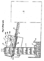
- a usual feeding system 1 is used for feeding preforms P to a downstream machine 2, for example a blow-moulding machine.
- the feeding system 1 comprises a bin 10 wherein the preforms P are dumped in bulk, and a feed-elevator 11 for removing the preforms from the bin 10 and for lifting up the preforms and dropping the preforms P at a pre-established rate into the upper part of an apparatus 12 for unscrambling and aligning the preforms.
- This apparatus 12 comprises a trough 120 and two rotary alignment rollers 121 which are mounted inside the trough 120.
- the axis of rotation 121a of each roller 121 is inclined to the horizontal.
- the rollers 121 are substantially parallel to each other, and are separated from each other in such a way to leave a space along and between the rollers for the body B of the preforms P.
- the distance between the two rollers 121 is however sufficiently small for enabling the two rollers to retain a preform P in its upright position by its neck support ring C.
- the two rollers are driven in rotation in two opposite directions ( figure 5 / arrows F).
- the preforms P fall in the trough 120 onto the alignment rollers 121.
- the preforms P tend to move and to be oriented between the rollers 121 in an upright position ( figure 5 ).
- Correctly oriented preforms are thus aligned and supported on the two rollers 121 by their neck support ring C, while the body B of the preforms hangs down between the rollers 121.
- the aligned and correctly oriented preforms P slide under the effect of gravity along the inclined alignment rollers 121 down to a feed rail 13 which guides the preforms down to the entry of the downstream machine 2. In this feed rail 13, the preforms P gather in a continuous line at the entry of the downstream machine 2.
- the sliding direction of the preforms onto the rollers 121 through the unscrambling and aligning apparatus 12 is identified by arrow A on the figures.
- the words "upstream” and “downstream” used therein are defined in reference to this sliding direction A.
- the apparatus 12 further comprises rotary pushing means 122 which are mounted above the two rotary rollers 121. These rotary pushing means 122 are used for pushing back preforms that are not correctly oriented and positioned between the two rollers 121 (like preforms P' on figure 1 ), and also nested preforms that can be correctly oriented and supported by the rollers 21 by the neck support ring C of the lower nested preform.
- theses rotary pushing means 122 are constituted by a rotary wheel comprising a rotary shaft 122a fitted with blades 122b.
- the axis of rotation of the shaft 122a is substantially perpendicular to the axis of rotation 121a of the rollers 121.
- the shaft 122a is driven in rotation at a pre-established speed in the direction identified by arrow G on the figures.
- the blades 122b of the wheel sweep the space above the rollers 121 and thus push back preforms that are not correctly oriented or nested preforms.
- a novel guide 3 is mounted above the rollers 121 and is used in combination with the rotary pushing means 122.
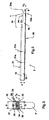
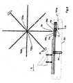
- FIGS. 2 and 3 show a particular structure for this guide 3, which is now going to be described in details, but bearing in mind that the invention is not limited however to this particular structure.
- the guide 3 is constituted by an inverted U-shaped profile, for example a stainless hot rolled flat bar, comprising two main vertical sidewalls 30 joined together by an upper wall 31.
- the two main vertical sidewalls 30 and the upper wall 31 delimit an internal channel 32 of height H and width W for the preform neck ( figure 3 ).
- Threaded holes 31a are pierced through the upper walls 31, and are used for fastening the guide 3 above the rollers 121 by means for example of screws 31 b (see e.g. figure 4 ).
- the guide 3 At its upstream end, the guide 3 comprises an upper L-shaped cut 33. In the region of this cut 33, the guide 3 has no upper wall, but has only upstream sidewalls 34 of smaller height h which are an extension of the main sidewalls 30. Referring to figure 3 , the distance W (i.e. width of channel 32) between the sidewalls 30 (or between the upstream sidewalls 34 of smaller height h) is preferably smaller than the diameter D of the neck support ring C of a preform P.
- the guide 3 is mounted above and in-between the two rollers 121.
- the lower edges 35 of the sidewalls 30 and 34 are parallel to the axis 121a of the rollers 121 and are close to the surface of the rollers 121.
- the distance between these lower edges 35 and the surface of the rollers 121 is sufficient for allowing the neck support ring C of a preform P, which is correctly oriented and suspended on the rollers 121 in its upright position, to slide between the lower edges 35 and the surface of the rollers 121.
- the lower edges 35 of the sidewalls 34 are bevelled at their upstream end 35a [ figure 2 / angle ⁇ ] in order to facilitate the entrance of the neck support ring C of a correctly oriented preform (P1) between said lower edges 35 and the rollers 121.
- the guide 3 is fastened with regard to the bladed wheel 122 in such way that the upstream front edge 31c of the upper wall 31 is positioned underneath the bladed wheel 122, more particularly at a position downstream from the axis of rotation 122c of the bladed wheel 122. Furthermore, the upstream front edges 34a of the two sidewalls 34 of smaller height h are positioned underneath the bladed wheel 122, in particular upstream from the axis of rotation 122c of the bladed wheel 122.
- the upper wall 31 does not stop the rotation of blades 122b, and the height h of the sidewalls 34 is also sufficiently small for allowing the rotation of the blades 122.
- the stopped nested preforms P4/P5 are most often lifted up onto the upper edges 34b of the sidewall 34, and are thus brought upwardly into contact with the rotary blades 122b of the wheel 122, and pushed back for recycling by the bladed wheel 122.
- the nested preforms P4/P5 are positioned onto the upper edges 34 of the sidewalls 34, they are stopped vertically by the upper edges 34a and are thus necessarily maintained at level that is sufficiently close to the rotary blade 122b for obtaining a reliable push back of the preforms by the blades.
- the nested preforms P4/P5 are positioned onto the upper edges 34b of the sidewalls 34, they can not slide down beyond the wheel 122 because they are stopped at least by the upstream front edge 31 c of the upper wall 31.
- nested preforms P4/P5 that have been stopped by the front edges 34a are displaced in such a way that the lower preform P4 becomes correctly oriented and positioned between rollers 121.
- the correctly oriented nested preforms P4/P5 can pass trough the sidewalls 34, with the neck support ring C of the lower preform P4 being guided between the lower edges 35 of the sidewalls 34 and the rollers 121.
- an incorrectly oriented preform alone slides on the rollers 121 down to the guide 3 it is also firstly stopped by the front edges 34a of the two sidewalls 34 of smaller height h, and then most often lifted up onto the upper edges 34b of the sidewalls 34 and brought upwardly into contact with the blades 122b of the wheel, and then necessarily pushed back for recycling by the bladed wheel 122.
- this correctly oriented preform slides down through the guide 3 underneath the lower edge 35 of the guide 3 without being stopped by the front edge 31c (like preform P1 on figure 4 , 6 or 7 ), and without coming into contact with the bladed wheel 122.
- the front edges 34a of the sidewalls 34 are designed in order to facilitate the lifting of a preform or nested preforms onto the upper edges 34b under the pressure of the other preforms continuously fed behind.
- the front edges 34a of the sidewalls 34 are inclined with reference to a planes that is perpendicular to the axis of rotation 121a of the rollers 121 at a front angle a of value greater than 0°.
- a suitable value for this front angle a is for example around 10°.
- the guide 3 is not necessarily made of one piece, but can be constituted by a monolithic assembly.
- the guide 3 could be made of two separated elements: upstream guiding means 34 for lifting up incorrectly oriented preforms or incorrectly oriented nested preforms and separated downstream stopping means 30, 31.
- the downstream stopping means could be made only of one stop like the upper wall 31 (i.e. without the sidewalls 30).
- the guide 3 could be only constituted by the sidewalls 30 and upper wall 31 (i.e.
- the front edges 34a of the sidewalls 34 are positioned underneath the rotary pushing means 122. In another variant, theses front edges 34a could be also positioned upstream from the rotary pushing means 122.
Landscapes
- Engineering & Computer Science (AREA)
- Mechanical Engineering (AREA)
- Manufacturing & Machinery (AREA)
- Blow-Moulding Or Thermoforming Of Plastics Or The Like (AREA)
Claims (15)
- Préformes comportant un corps sensiblement tubulaire qui est fermé à une extrémité inférieure et est ouvert à l'autre extrémité supérieure et une bague de col dans leur partie supérieure, proche de leur goulot, et appareil (12) pour mettre en ordre et aligner lesdites préformes, ledit appareil comprenant deux rouleaux d'alignement sensiblement parallèles (121)adaptés pour supporter et suspendre un préforme bien orientée en position verticale par l'intermédiaire sa bague de col et des moyens de poussée rotatifs (122) montés au-dessus desdits rouleaux d'alignement pour repousser des préformes mal orientées ou des préformes emboîtées, ledit appareil étant caractérisé par au moins une des caractéristiques suivantes (i) ou (ii) :(i) il comprend des moyens d'arrêt (30, 31) montés au-dessus des rouleaux d'alignement (121) pour arrêter des préformes emboîtées bien orientées (P2/P3) ou une préforme mal orientée ou des préformes emboîtées mal orientées (P4/P5) sous les moyens de poussée rotatifs (122) jusqu'à ce que les moyens de poussée rotatifs aient repoussé la(les) préforme(s) arrêtée(s), lesdits moyens d'arrêt (30, 31) étant adaptés pour laisser une préforme bien orientée glisser sur les rouleaux d'alignement,(ii) il comprend des moyens de guidage (34) pour soulever une préforme mal orientée ou des préformes emboîtées mal orientées (P4/P5) pour la ou les mettre en contact avec les moyens de poussée rotatifs (122), lesdits moyens de guidage (34) étant adaptés pour laisser une préforme bien orientée glisser sur les rouleaux d'alignement.
- Préformes et appareil selon la revendication 1, caractérisés par les deux caractéristiques (i) et (ii), et dans lequel les moyens de guidage (34) sont positionnés en amont des moyens d'arrêt (30, 31).
- Préformes et appareil selon la revendication 2, dans lesquels les moyens de guidage (34) s'étendent vers le bas vers les moyens d'arrêt (30, 31).
- Préformes et appareil selon la revendication 1 ou 2, dans lesquels les moyens de guidage sont constitués par deux parois latérales parallèles (34).
- Préformes et appareil selon la revendication 4, dans lesquels lesdites parois latérales (34) sont séparées par une distance (W) qui est inférieure au diamètre (D) de la bague de support de col (C) d'une préforme.
- Préformes et appareil selon la revendication 4 ou 5, dans lesquels les bords avant (34a) des parois latérales (34) sont conçus pour faciliter le levage de la(des) préforme (s) sur les bords supérieurs (34b) des parois latérales.
- Préformes et appareil selon la revendication 6, dans lesquels les bords avant (34a) des parois latérales (34) sont inclinés d'un angle aigu (α) d'une valeur supérieure à 0° par rapport à un plan (E), qui est perpendiculaire à l'axe de rotation (121a) des rouleaux (121).
- Préformes et appareil selon la revendication 7, dans lesquels l'angle aigu (α) est d'environ 10°.
- Préformes et appareil selon l'une quelconque de revendications 4 à 8, dans lesquels les bords inférieurs (35) des parois latérales (34) sont biseautés au niveau de leur extrémité amont (35a) afin de faciliter l'entrée de la bague de support de col (C) d'une préforme bien orientée (P1) entre lesdits bords inférieurs (35) et les rouleaux (121).
- Préformes et appareil selon l'une quelconque des revendications 2 à 9, dans lesquels les moyens d'arrêt et les moyens de guidage sont constitués par un guide (3) comprenant deux parois latérales principales (30) d'une hauteur (H), qui sont jointes ensemble par une paroi supérieure (31), et comprenant deux parois latérales (34) de plus faible hauteur (h) qui sont une extension desdites parois latérales principales (30).
- Préformes et appareil selon l'une quelconque des revendications 1 à 10, dans lesquels les moyens de poussée rotatifs (122) sont constitués par une roue à ailettes.
- Système d'alimentation (1) pour alimenter une machine située en aval (2) avec des préformes alignées et bien orientées (P), et comprenant un bac de stockage (10) pour stocker des préformes (P) en vrac, un élévateur d'alimentation (11) pour retirer les préformes (P) du bac de stockage (10) et pour soulever les préformes (P) et laisser tomber les préformes (P) à une cadence préétablie dans un appareil (12) pour mettre en ordre et aligner les préformes, caractérisé en ce qu'il comprend des préformes et appareil selon l'une quelconque des revendications 1 à 11.
- Utilisation de préformes et d'un appareil selon l'une quelconque des revendications 1 à 11 pour alimenter une machine située en aval (2) avec des préformes alignées et bien orientées (P).
- Utilisation selon la revendication 13, dans laquelle la machine située en aval (2) est une machine de moulage par soufflage.
- Système pour fabriquer des récipients en plastique moulés par soufflage, et comprenant une machine de moulage par soufflage (2) et un appareil pour mettre en ordre et aligner des préformes, caractérisé en ce qu'il comprend des préformes et un appareil selon l'une quelconque des revendications 1 à 11 pour alimenter la machine de moulage par soufflage (2) avec des préformes alignées et bien orientées (P).
Priority Applications (5)
| Application Number | Priority Date | Filing Date | Title |
|---|---|---|---|
| EP07022926.5A EP2065320B2 (fr) | 2007-11-27 | 2007-11-27 | Appareil pour débrouiller et aligner des préformes |
| ES07022926T ES2347886T5 (es) | 2007-11-27 | 2007-11-27 | Aparato para poner en orden y alinear preformas |
| DE602007007346T DE602007007346D1 (de) | 2007-11-27 | 2007-11-27 | Vorrichtung zur Sortierung und Ausrichtung von Vorformen |
| US12/744,618 US8337193B2 (en) | 2007-11-27 | 2008-08-01 | Apparatus for unscrambling and aligning preforms |
| PCT/EP2008/006369 WO2009068121A1 (fr) | 2007-11-27 | 2008-08-01 | Dispositif pour mettre en ordre et aligner des préformes |
Applications Claiming Priority (1)
| Application Number | Priority Date | Filing Date | Title |
|---|---|---|---|
| EP07022926.5A EP2065320B2 (fr) | 2007-11-27 | 2007-11-27 | Appareil pour débrouiller et aligner des préformes |
Publications (3)
| Publication Number | Publication Date |
|---|---|
| EP2065320A1 EP2065320A1 (fr) | 2009-06-03 |
| EP2065320B1 EP2065320B1 (fr) | 2010-06-23 |
| EP2065320B2 true EP2065320B2 (fr) | 2013-08-21 |
Family
ID=39345201
Family Applications (1)
| Application Number | Title | Priority Date | Filing Date |
|---|---|---|---|
| EP07022926.5A Active EP2065320B2 (fr) | 2007-11-27 | 2007-11-27 | Appareil pour débrouiller et aligner des préformes |
Country Status (5)
| Country | Link |
|---|---|
| US (1) | US8337193B2 (fr) |
| EP (1) | EP2065320B2 (fr) |
| DE (1) | DE602007007346D1 (fr) |
| ES (1) | ES2347886T5 (fr) |
| WO (1) | WO2009068121A1 (fr) |
Families Citing this family (18)
| Publication number | Priority date | Publication date | Assignee | Title |
|---|---|---|---|---|
| CH699222A1 (de) * | 2008-07-17 | 2010-01-29 | M Tanner Ag | Vorrichtung und Verfahren zum Vereinzeln von zylindrischen Körpern. |
| CH702406A1 (de) | 2009-12-11 | 2011-06-15 | M Tanner Ag | Vorrichtung zum Aussortieren von falsch positionierten zylindrischen Körpern in einer Vereinzelungs- und Fördereinrichtung. |
| US8269661B2 (en) * | 2010-10-14 | 2012-09-18 | Texas Instruments Incorporated | Pipelined ADC having a three-level DAC elements |
| CH704401A1 (de) * | 2011-01-28 | 2012-07-31 | M Tanner Ag | Fördereinrichtung für zylindrische Körper, mit in Förderrichtung geneigten Ablaufschienen. |
| DE102011016858A1 (de) | 2011-04-13 | 2012-10-18 | Krones Aktiengesellschaft | Vorrichtung und Verfahren zum Transportieren von Kunststoffvorformlingen |
| DE102011109542A1 (de) * | 2011-08-05 | 2013-02-07 | Krones Aktiengesellschaft | Transport- und Aussondervorrichtung für Kunststoffvorformlinge |
| DE102012103079A1 (de) * | 2012-04-10 | 2013-10-10 | Krones Ag | Rollenförderer für Kunststoffvorformlinge |
| CN104245276B (zh) * | 2012-04-24 | 2016-10-12 | 日精Asb机械株式会社 | 预成形坯供给装置 |
| DE102012011763A1 (de) * | 2012-06-15 | 2013-12-19 | Khs Corpoplast Gmbh | Vorrichtung zum Transport von Vorformlingen |
| DE102012011762A1 (de) * | 2012-06-15 | 2013-12-19 | Khs Corpoplast Gmbh | Vereinzelungsvorrichtung für Vorformlinge mit einer Einrichtung zum Aussondern von falsch positionierten Vorformlingen |
| DE102012017699A1 (de) * | 2012-09-07 | 2014-03-13 | Khs Corpoplast Gmbh | Vereinzelungsvorrichtung für Vorformlinge |
| CN106414028B (zh) * | 2014-06-18 | 2019-04-09 | 萨克米伊莫拉有限公司 | 用于供给预成型件的系统 |
| DE102014012528A1 (de) * | 2014-08-28 | 2016-03-03 | Khs Corpoplast Gmbh | Vorrichtung und Verfahren zum Transport von Vorformlingen im Bereich einer Blasmaschine |
| CN105711060B (zh) * | 2014-11-05 | 2017-12-08 | 柳州市精业机器有限公司 | 多工位旋转成型机 |
| FR3051780A1 (fr) * | 2016-05-25 | 2017-12-01 | Sidel Participations | Procede de deblocage du defilement de corps creux dans un convoyeur a glissiere |
| DE102019105824A1 (de) * | 2019-03-07 | 2020-09-10 | Khs Corpoplast Gmbh | Vereinzelungsvorrichtung für Vorformlinge |
| CN112078871B (zh) * | 2020-09-09 | 2022-03-01 | 山东铭源包装科技有限公司 | 一种热敏电阻生产用的包装机 |
| CN113702656B (zh) * | 2021-08-27 | 2024-06-07 | 中元汇吉生物技术股份有限公司 | 进料排序装置及样本分析仪 |
Citations (8)
| Publication number | Priority date | Publication date | Assignee | Title |
|---|---|---|---|---|
| US2615556A (en) † | 1945-09-11 | 1952-10-28 | Selas Corp Of America | Apparatus for orienting and aligning cylindrical-shaped articles |
| US2988247A (en) † | 1956-07-10 | 1961-06-13 | Burton R Garrett | Combined hopper, feeder and counter |
| US3346095A (en) † | 1965-06-09 | 1967-10-10 | Dixon Automatic Tool | Vibratory feeding mechanism |
| US3517797A (en) † | 1967-09-19 | 1970-06-30 | Giovanni Daleffe | Thread bobbin tube aligner |
| US4223778A (en) † | 1978-05-12 | 1980-09-23 | Owens-Illinois, Inc. | Parison handling assemblies and methods for handling parisons |
| US4244459A (en) † | 1978-01-26 | 1981-01-13 | Garrett Burton R | Parison unscrambler |
| WO2006084831A1 (fr) † | 2005-02-09 | 2006-08-17 | Nov Hau Ag Engineering | Dispositif et procede pour redresser des ebauches destinees a produire des produits en plastique par soufflage sur matrice |
| US20070108018A1 (en) † | 2003-12-23 | 2007-05-17 | Alain Charpentier | Preform feeder system, particularly of a receptacle blowing machine, comprising means for ejecting badly positioned preforms |
Family Cites Families (8)
| Publication number | Priority date | Publication date | Assignee | Title |
|---|---|---|---|---|
| USRE25297E (en) * | 1962-12-11 | Combined hopper | ||
| SE393533C (sv) * | 1975-09-11 | 1979-01-15 | Gambro Ab | Anordning for diffusion av emnen mellan tva strommande fluider via semipermeabla membran |
| US4224459A (en) | 1978-10-30 | 1980-09-23 | Owens-Corning Fiberglas Corporation | Electric melt furnace-electrodes inclined toward each other to vary the firing path during steady state operation and to create hot spots after heat loss or during start-up |
| US4418482A (en) * | 1982-09-30 | 1983-12-06 | Aidlin Samuel S | Device and method for feeding hot articles to prevent mutual adherence thereof |
| FR2675481B1 (fr) * | 1991-04-16 | 1993-08-20 | Sidel Sa | Dispositif de convoyage de preformes agence pour eliminer des preformes emboitees les unes dans les autres. |
| FR2816297B1 (fr) * | 2000-11-03 | 2003-01-10 | Sidel Sa | Systeme d'alimentation de preformes destine notamment a une machine de soufflage de recipients |
| FR2864050B1 (fr) * | 2003-12-23 | 2007-04-06 | Sidel Sa | Systeme d'alimentation de preformes comportant un dispositif d'elimination selective des preformes mal positionnees de type allonge |
| WO2007043279A1 (fr) * | 2005-10-11 | 2007-04-19 | Toyo Seikan Kaishya, Ltd. | Appareil de refroidissement des preformes et procede de refroidissement des preformes |
-
2007
- 2007-11-27 ES ES07022926T patent/ES2347886T5/es active Active
- 2007-11-27 DE DE602007007346T patent/DE602007007346D1/de active Active
- 2007-11-27 EP EP07022926.5A patent/EP2065320B2/fr active Active
-
2008
- 2008-08-01 WO PCT/EP2008/006369 patent/WO2009068121A1/fr active Application Filing
- 2008-08-01 US US12/744,618 patent/US8337193B2/en active Active
Patent Citations (8)
| Publication number | Priority date | Publication date | Assignee | Title |
|---|---|---|---|---|
| US2615556A (en) † | 1945-09-11 | 1952-10-28 | Selas Corp Of America | Apparatus for orienting and aligning cylindrical-shaped articles |
| US2988247A (en) † | 1956-07-10 | 1961-06-13 | Burton R Garrett | Combined hopper, feeder and counter |
| US3346095A (en) † | 1965-06-09 | 1967-10-10 | Dixon Automatic Tool | Vibratory feeding mechanism |
| US3517797A (en) † | 1967-09-19 | 1970-06-30 | Giovanni Daleffe | Thread bobbin tube aligner |
| US4244459A (en) † | 1978-01-26 | 1981-01-13 | Garrett Burton R | Parison unscrambler |
| US4223778A (en) † | 1978-05-12 | 1980-09-23 | Owens-Illinois, Inc. | Parison handling assemblies and methods for handling parisons |
| US20070108018A1 (en) † | 2003-12-23 | 2007-05-17 | Alain Charpentier | Preform feeder system, particularly of a receptacle blowing machine, comprising means for ejecting badly positioned preforms |
| WO2006084831A1 (fr) † | 2005-02-09 | 2006-08-17 | Nov Hau Ag Engineering | Dispositif et procede pour redresser des ebauches destinees a produire des produits en plastique par soufflage sur matrice |
Also Published As
| Publication number | Publication date |
|---|---|
| US20100255142A1 (en) | 2010-10-07 |
| ES2347886T3 (es) | 2010-11-23 |
| WO2009068121A1 (fr) | 2009-06-04 |
| EP2065320A1 (fr) | 2009-06-03 |
| ES2347886T5 (es) | 2013-12-26 |
| DE602007007346D1 (de) | 2010-08-05 |
| EP2065320B1 (fr) | 2010-06-23 |
| US8337193B2 (en) | 2012-12-25 |
Similar Documents
| Publication | Publication Date | Title |
|---|---|---|
| EP2065320B2 (fr) | Appareil pour débrouiller et aligner des préformes | |
| US7337893B2 (en) | Preform feeder system, particularly of a receptacle blowing machine, comprising means for ejecting badly positioned preforms | |
| US6968936B2 (en) | System for supplying preforms in particular for a container blowing machine | |
| EP2544978B1 (fr) | Système de convoyeur et procédé de triage de paquets | |
| US9561614B2 (en) | Method and apparatus for transporting articles to a station | |
| US10343852B2 (en) | Device and method for delivering oriented elements | |
| EP1458636B1 (fr) | Systeme et procede de transport et d'accumulation de produits | |
| US9714144B2 (en) | Product conveying and accumulation system | |
| EP2886297B1 (fr) | Machine de moulage par soufflage | |
| US20100193325A1 (en) | Method of conveying preforms and high speed device for tipping preforms | |
| EP2196417B1 (fr) | Dispositif pour orienter des objets, notamment des bouchons | |
| JP6251561B2 (ja) | プリフォームの整列搬送装置 | |
| US9333697B2 (en) | Preform supplying apparatus | |
| JP2016120718A (ja) | 内容物を含む封筒の処理方法および装置 | |
| EP1989130B1 (fr) | Dispositif de convoyage mecanique pour conteneurs plastiques vides munis d'un collier, en condition suspendue | |
| US20120085620A1 (en) | Device for orienting objects | |
| MX2008010445A (es) | Transportador equipado con un dispositivo para separar tapas desalineadas. | |
| CN103818712A (zh) | 用来把至少一个成形件输送到饮料灌装设备中的装置 | |
| JP2014073895A (ja) | プリフォーム供給装置 | |
| JP7461060B2 (ja) | 物品の分離供給装置 | |
| EP2409785B1 (fr) | Dispositif singulateur pour objets postaux doté d'une fonction anti-glisse | |
| JPH0970828A (ja) | プリフォーム冷却搬送装置 | |
| JP2019073374A (ja) | 搬送装置 | |
| JPH11222214A (ja) | 物品の整列搬送装置及び物品の搬出方法 |
Legal Events
| Date | Code | Title | Description |
|---|---|---|---|
| PUAI | Public reference made under article 153(3) epc to a published international application that has entered the european phase |
Free format text: ORIGINAL CODE: 0009012 |
|
| 17P | Request for examination filed |
Effective date: 20080618 |
|
| AK | Designated contracting states |
Kind code of ref document: A1 Designated state(s): AT BE BG CH CY CZ DE DK EE ES FI FR GB GR HU IE IS IT LI LT LU LV MC MT NL PL PT RO SE SI SK TR |
|
| AX | Request for extension of the european patent |
Extension state: AL BA HR MK RS |
|
| GRAP | Despatch of communication of intention to grant a patent |
Free format text: ORIGINAL CODE: EPIDOSNIGR1 |
|
| AKX | Designation fees paid |
Designated state(s): DE ES FR GB IT |
|
| GRAS | Grant fee paid |
Free format text: ORIGINAL CODE: EPIDOSNIGR3 |
|
| GRAA | (expected) grant |
Free format text: ORIGINAL CODE: 0009210 |
|
| AK | Designated contracting states |
Kind code of ref document: B1 Designated state(s): DE ES FR GB IT |
|
| REF | Corresponds to: |
Ref document number: 602007007346 Country of ref document: DE Date of ref document: 20100805 Kind code of ref document: P |
|
| PLBI | Opposition filed |
Free format text: ORIGINAL CODE: 0009260 |
|
| 26 | Opposition filed |
Opponent name: EGLI, RICHARD A. Effective date: 20110322 |
|
| PLAX | Notice of opposition and request to file observation + time limit sent |
Free format text: ORIGINAL CODE: EPIDOSNOBS2 |
|
| REG | Reference to a national code |
Ref country code: DE Ref legal event code: R026 Ref document number: 602007007346 Country of ref document: DE Effective date: 20110322 |
|
| PLAF | Information modified related to communication of a notice of opposition and request to file observations + time limit |
Free format text: ORIGINAL CODE: EPIDOSCOBS2 |
|
| PLBB | Reply of patent proprietor to notice(s) of opposition received |
Free format text: ORIGINAL CODE: EPIDOSNOBS3 |
|
| PG25 | Lapsed in a contracting state [announced via postgrant information from national office to epo] |
Ref country code: IT Free format text: LAPSE BECAUSE OF NON-PAYMENT OF DUE FEES Effective date: 20101127 |
|
| PLAY | Examination report in opposition despatched + time limit |
Free format text: ORIGINAL CODE: EPIDOSNORE2 |
|
| PLAH | Information related to despatch of examination report in opposition + time limit modified |
Free format text: ORIGINAL CODE: EPIDOSCORE2 |
|
| RIC2 | Information provided on ipc code assigned after grant |
Ipc: B65G 11/16 20060101AFI20130123BHEP |
|
| PUAH | Patent maintained in amended form |
Free format text: ORIGINAL CODE: 0009272 |
|
| STAA | Information on the status of an ep patent application or granted ep patent |
Free format text: STATUS: PATENT MAINTAINED AS AMENDED |
|
| 27A | Patent maintained in amended form |
Effective date: 20130821 |
|
| AK | Designated contracting states |
Kind code of ref document: B2 Designated state(s): DE ES FR GB IT |
|
| REG | Reference to a national code |
Ref country code: DE Ref legal event code: R102 Ref document number: 602007007346 Country of ref document: DE Effective date: 20130821 |
|
| REG | Reference to a national code |
Ref country code: ES Ref legal event code: DC2A Ref document number: 2347886 Country of ref document: ES Kind code of ref document: T5 Effective date: 20131226 |
|
| REG | Reference to a national code |
Ref country code: FR Ref legal event code: PLFP Year of fee payment: 9 |
|
| REG | Reference to a national code |
Ref country code: DE Ref legal event code: R081 Ref document number: 602007007346 Country of ref document: DE Owner name: PLASTIPAK BAWT S.A.R.L., LU Free format text: FORMER OWNER: LA SEDA DE BARCELONA S.A., EL PRAT DE LLOBREGAT, BARCELONA, ES Ref country code: DE Ref legal event code: R082 Ref document number: 602007007346 Country of ref document: DE Representative=s name: LEONHARD & PARTNER PATENTANWAELTE, DE |
|
| REG | Reference to a national code |
Ref country code: GB Ref legal event code: 732E Free format text: REGISTERED BETWEEN 20160218 AND 20160224 |
|
| REG | Reference to a national code |
Ref country code: FR Ref legal event code: TP Owner name: PLASTIPAK BAWT S.A.R.L., LU Effective date: 20160309 |
|
| REG | Reference to a national code |
Ref country code: ES Ref legal event code: PC2A Owner name: PLASTIPAK BAWT S.A.R.L. Effective date: 20160510 |
|
| REG | Reference to a national code |
Ref country code: FR Ref legal event code: PLFP Year of fee payment: 10 |
|
| REG | Reference to a national code |
Ref country code: FR Ref legal event code: PLFP Year of fee payment: 11 |
|
| REG | Reference to a national code |
Ref country code: FR Ref legal event code: PLFP Year of fee payment: 12 |
|
| REG | Reference to a national code |
Ref country code: DE Ref legal event code: R082 Ref document number: 602007007346 Country of ref document: DE Representative=s name: LEONHARD, REIMUND, DIPL.-ING., DE |
|
| PGFP | Annual fee paid to national office [announced via postgrant information from national office to epo] |
Ref country code: GB Payment date: 20231013 Year of fee payment: 17 |
|
| PGFP | Annual fee paid to national office [announced via postgrant information from national office to epo] |
Ref country code: ES Payment date: 20231208 Year of fee payment: 17 |
|
| PGFP | Annual fee paid to national office [announced via postgrant information from national office to epo] |
Ref country code: IT Payment date: 20231113 Year of fee payment: 17 Ref country code: FR Payment date: 20231010 Year of fee payment: 17 Ref country code: DE Payment date: 20231010 Year of fee payment: 17 |