EP2065288B1 - Railway positioning system - Google Patents
Railway positioning system Download PDFInfo
- Publication number
- EP2065288B1 EP2065288B1 EP07023053A EP07023053A EP2065288B1 EP 2065288 B1 EP2065288 B1 EP 2065288B1 EP 07023053 A EP07023053 A EP 07023053A EP 07023053 A EP07023053 A EP 07023053A EP 2065288 B1 EP2065288 B1 EP 2065288B1
- Authority
- EP
- European Patent Office
- Prior art keywords
- wayside
- measurement device
- speed measurement
- coding
- positioning system
- Prior art date
- Legal status (The legal status is an assumption and is not a legal conclusion. Google has not performed a legal analysis and makes no representation as to the accuracy of the status listed.)
- Not-in-force
Links
- 238000005259 measurement Methods 0.000 claims abstract description 23
- 230000001939 inductive effect Effects 0.000 claims abstract description 4
- 230000018199 S phase Effects 0.000 claims 1
- 239000002184 metal Substances 0.000 abstract description 8
- 125000004122 cyclic group Chemical group 0.000 description 2
- 238000001514 detection method Methods 0.000 description 1
- 230000014509 gene expression Effects 0.000 description 1
- 230000002452 interceptive effect Effects 0.000 description 1
- 238000012423 maintenance Methods 0.000 description 1
- 238000000034 method Methods 0.000 description 1
- 230000011664 signaling Effects 0.000 description 1
- 230000009466 transformation Effects 0.000 description 1
- 239000013598 vector Substances 0.000 description 1
Images

Classifications
-
- B—PERFORMING OPERATIONS; TRANSPORTING
- B61—RAILWAYS
- B61L—GUIDING RAILWAY TRAFFIC; ENSURING THE SAFETY OF RAILWAY TRAFFIC
- B61L3/00—Devices along the route for controlling devices on the vehicle or train, e.g. to release brake or to operate a warning signal
- B61L3/02—Devices along the route for controlling devices on the vehicle or train, e.g. to release brake or to operate a warning signal at selected places along the route, e.g. intermittent control simultaneous mechanical and electrical control
- B61L3/08—Devices along the route for controlling devices on the vehicle or train, e.g. to release brake or to operate a warning signal at selected places along the route, e.g. intermittent control simultaneous mechanical and electrical control controlling electrically
- B61L3/12—Devices along the route for controlling devices on the vehicle or train, e.g. to release brake or to operate a warning signal at selected places along the route, e.g. intermittent control simultaneous mechanical and electrical control controlling electrically using magnetic or electrostatic induction; using radio waves
- B61L3/121—Devices along the route for controlling devices on the vehicle or train, e.g. to release brake or to operate a warning signal at selected places along the route, e.g. intermittent control simultaneous mechanical and electrical control controlling electrically using magnetic or electrostatic induction; using radio waves using magnetic induction
-
- B—PERFORMING OPERATIONS; TRANSPORTING
- B61—RAILWAYS
- B61L—GUIDING RAILWAY TRAFFIC; ENSURING THE SAFETY OF RAILWAY TRAFFIC
- B61L25/00—Recording or indicating positions or identities of vehicles or trains or setting of track apparatus
- B61L25/02—Indicating or recording positions or identities of vehicles or trains
- B61L25/025—Absolute localisation, e.g. providing geodetic coordinates
-
- B—PERFORMING OPERATIONS; TRANSPORTING
- B61—RAILWAYS
- B61L—GUIDING RAILWAY TRAFFIC; ENSURING THE SAFETY OF RAILWAY TRAFFIC
- B61L25/00—Recording or indicating positions or identities of vehicles or trains or setting of track apparatus
- B61L25/02—Indicating or recording positions or identities of vehicles or trains
- B61L25/026—Relative localisation, e.g. using odometer
Definitions
- the invention relates to positioning systems for railways. Such devices measure the absolute and relative position and speed of railway vehicles and supply their measured values to driver displays, signalling, traction control systems and other users.
- absolute positioning refers to preset mile or kilometre positions on a track which is recorded in files and on wayside milestones.
- Relative positioning refers to a distance travelled since an earlier point in time.
- Satellite positioning combines absolute and relative positioning, see e. g. DE 19731110 A1 . However, data availability in tunnels and narrow valleys is low precluding its use as a universal solution.
- Magnetic speed measurement devices using pulsed coils to create magnetic markers in the rail are known from DE 2164312 and FR-A-2673901 .
- absolute and relative positioning have been combined in one system using a speed measurement device measuring induced magnetic fields known from US 5,825,177 which recognises patterns in the track like the rail gaps at points. This method only has limited coding opportunities and due to the similarity between points, dependability is not optimised.
- One object of this invention is a cost and performance optimised absolute and relative positioning system.
- the railway positioning system of the present invention comprises:
- a coded wayside tag provides a coding recognisable by the on-board speed measurement device.
- magnetic patterns can be analysed in the same way as the point detection described above.
- the position can be detected in a safe way.
- the coding may represent telegrams which contain safety measures like cyclic redundancy checks if needed.
- the tag is simple and cheap. It can be mounted some centimetres aside of the rail and/or slightly below the rail head. Therefore, it doesn't interfere with ballast maintenance.
- Quadrature Amplitude Modulation provides good signal to noise ratio.
- a high information rate per tag length can achieved, in particular if one information unit represents a 4-bit-digital word.
- a safety telegram format can be used for coding with the basic same performance of availability and wrong side failure rate as for a state-of-the-art tag system.
- the coding can also be able to detect in which direction the vehicle is entering the tag. If the telegram is read by two autonomous sensors of the speed measurement device and if the result shall be the same, the number of Cyclic Redundancy Check bits will be relatively low.
- a 15 to 16 bit safety telegram will give a range of 500 to 700 unique telegrams with a reasonable distribution of 0 and 1 bits.
- the received signal is varying over time and the bit rate is depending on the speed of the vehicle.
- a transformation of the time varying signal to a spatial distribution can be achieved and the telegram can be read.
- a bar may be fastened on the rail foot or on sleepers.
- the coding can be created by standard size metal blocks representing 1 and gaps representing 0.
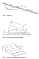
- the coded tag 1 comprises a bar 4 with several slots 3 in which metal blocks 2 of different sizes are mounted.
- the magnet speed measurement device can sense the amplitude and position along the travelling direction of signals generated by the wayside structure.
- the coded tag 1 exploits this by providing metal blocks 2 of different sizes as shown in figure 3 feeding back a signal to the speed measurement device 6 about proportional to the block size.
- the blocks 2 are mounted at selected locations along the travelling direction by fixing them with their bolts 5 in selected slots 3 of the bar 4 as shown in figure 2 .
- the speed measurement device 6 provides the current speed information.
- the vehicle then senses feed back signals with amplitudes proportional to the block sizes as shown in figure 4 where the signal of each of the speed measurements device's sensor is a dotted line and the combined signal is a solid line.
- the signals of the sensors have opposing signs so that equal amplitudes compensate.
- the time intervals when the feed back signals are registered are proportional to the positions where the blocks 2 are mounted at the bar 4. If the speed is not constant, the corresponding recalculation has to be effectuated.
- the coded tag 1 is mounted laterally to the rail head 7 at a height not interfering with the wheels of the vehicles.
- a railway positioning system provides an on-board speed measurement device (6) inducing eddy currents in the wayside structure at two spots along the travelling direction, measuring the variations of the magnetic field emitted by the wayside structure and determining position and speed by correlating the 2 measured signals known from US5825177 and a wayside coded tag (1) providing a coding recognisable by the on-board speed measurement device (6).
- the coded tag (1) consists of a bar (4) with several slots (3) in which metal blocks (2) of different sizes are mounted. The block sizes and positions are selected to represent a coding according to Quadrature Amplitude Modulation.
Landscapes
- Engineering & Computer Science (AREA)
- Mechanical Engineering (AREA)
- Train Traffic Observation, Control, And Security (AREA)
- Exposure Of Semiconductors, Excluding Electron Or Ion Beam Exposure (AREA)
- Control Of Position Or Direction (AREA)
- Radar Systems Or Details Thereof (AREA)
Abstract
Description
- The invention relates to positioning systems for railways. Such devices measure the absolute and relative position and speed of railway vehicles and supply their measured values to driver displays, signalling, traction control systems and other users. In the railway context, absolute positioning refers to preset mile or kilometre positions on a track which is recorded in files and on wayside milestones. Relative positioning refers to a distance travelled since an earlier point in time.
- Known solutions for relative positioning apply wheel rotation measurements, see e. g.
GB 388761 US 4,791,424 and induced magnetic fields measurements.
Known solutions for absolute positioning apply wayside tags in the form of electronic transponders, see e. g.EP 1813499 or track cable crossing locations, see e. g.
EP 0593910 . The need to provide 2 separate systems for absolute and relative positioning drives cost and the amount of hardware to be installed. Satellite positioning combines absolute and relative positioning, see e. g.DE 19731110 A1 . However, data availability in tunnels and narrow valleys is low precluding its use as a universal solution.
Magnetic speed measurement devices using pulsed coils to create magnetic markers in the rail are known fromDE 2164312 andFR-A-2673901 WO 01/66401 A1 US 5,825,177 which recognises patterns in the track like the rail gaps at points. This method only has limited coding opportunities and due to the similarity between points, dependability is not optimised. - One object of this invention is a cost and performance optimised absolute and relative positioning system.
- The object is met by a positioning system with a coded tag for a railway magnetic speed measurement device, in particular as defined in the claims which define the scope of the invention.
- The railway positioning system of the present invention comprises:
- an on-board speed measurement device,
- the device inducing eddy currents in a wayside structure at two spots along the travelling direction,
- the device measuring the variations of the magnetic field emitted by the wayside structure and determining position and speed by correlating the two measured signals.
- It is proposed that a coded wayside tag provides a coding recognisable by the on-board speed measurement device.
- E.g. by using analogue outputs of the magnetic speed measurement device, magnetic patterns can be analysed in the same way as the point detection described above. By creating a known signature at a certain position, the position can be detected in a safe way.
- The coding may represent telegrams which contain safety measures like cyclic redundancy checks if needed. The tag is simple and cheap. It can be mounted some centimetres aside of the rail and/or slightly below the rail head. Therefore, it doesn't interfere with ballast maintenance.
- For example, use of Quadrature Amplitude Modulation provides good signal to noise ratio. A high information rate per tag length can achieved, in particular if one information unit represents a 4-bit-digital word.
- If the telegrams are changed by a control device, information depending on the dynamic state of other systems can be transmitted to the speed measurement device, e. g. signal aspects. A safety telegram format can be used for coding with the basic same performance of availability and wrong side failure rate as for a state-of-the-art tag system.
- The coding can also be able to detect in which direction the vehicle is entering the tag. If the telegram is read by two autonomous sensors of the speed measurement device and if the result shall be the same, the number of Cyclic Redundancy Check bits will be relatively low.
- For example, a 15 to 16 bit safety telegram will give a range of 500 to 700 unique telegrams with a reasonable distribution of 0 and 1 bits. The received signal is varying over time and the bit rate is depending on the speed of the vehicle. By using the actual speed and the correlation between the 2 speed measurement device channels, a transformation of the time varying signal to a spatial distribution can be achieved and the telegram can be read.
A bar may be fastened on the rail foot or on sleepers. Alternatively, the coding can be created by standard size metal blocks representing 1 and gaps representing 0. - Examples of the invention will be described with reference to the attached drawings. Therein, interpretations and more detailed information concerning the expressions used above are given.
-
-
Figure 1 shows a preferred embodiment of the codedtag 1 withmetal blocks 2 of different sizes each attached to one ofseveral slots 3 in abar 4. -
Figure 2 shows ametal block 2 with abolt 5 for the block's fixation in one of theslots 3 of thebar 4 shown below. -
Figure 3 shows threeblocks 2 of different sizes representing the OAM amplitude modulation. -
Figure 4 shows the ideal signal sideal(x) an on-board magnet sensor generates when passing ametal block 2 with its front and rear sensor in travelling direction x. The combined signal is represented by the solid line. The signal of each of the sensors is represented by dotted lines. Along the section wM , both sensors received feed back from theblock 2. -
Figure 5 shows the cross-section of aspeed measurement device 6 according toUS5825177 , a rail head 7 and the codedtag 1. - As shown in
figure 1 , the codedtag 1 comprises abar 4 withseveral slots 3 in whichmetal blocks 2 of different sizes are mounted. The block sizes and positions are selected to represent a coding according to Quadrature Amplitude Modulation QAM which as known in the art maps 4-bit digital words to vectors of length or amplitude A and angle φ. Expressed as complex number this is
As shown inUS5825177 , the magnet speed measurement device can sense the amplitude and position along the travelling direction of signals generated by the wayside structure. The codedtag 1 exploits this by providingmetal blocks 2 of different sizes as shown infigure 3 feeding back a signal to thespeed measurement device 6 about proportional to the block size. Theblocks 2 are mounted at selected locations along the travelling direction by fixing them with theirbolts 5 in selectedslots 3 of thebar 4 as shown infigure 2 . When the railway vehicle travels along a codedtag 1, it senses thefirst blocks 2 which are arranged in a sequence representing a start indication. In parallel to reading the codedtag 1, thespeed measurement device 6 provides the current speed information. The vehicle then senses feed back signals with amplitudes proportional to the block sizes as shown infigure 4 where the signal of each of the speed measurements device's sensor is a dotted line and the combined signal is a solid line. The signals of the sensors have opposing signs so that equal amplitudes compensate.
At constant speed, the time intervals when the feed back signals are registered are proportional to the positions where theblocks 2 are mounted at thebar 4. If the speed is not constant, the corresponding recalculation has to be effectuated. As shown infigure 5 , thecoded tag 1 is mounted laterally to the rail head 7 at a height not interfering with the wheels of the vehicles. - The invention may be summarised by the following:
A railway positioning system provides an on-board speed measurement device (6) inducing eddy currents in the wayside structure at two spots along the travelling direction, measuring the variations of the magnetic field emitted by the wayside structure and determining position and speed by correlating the 2 measured signals known from
US5825177 and a wayside coded tag (1) providing a coding recognisable by the on-board speed measurement device (6). The coded tag (1) consists of a bar (4) with several slots (3) in which metal blocks (2) of different sizes are mounted. The block sizes and positions are selected to represent a coding according to Quadrature Amplitude Modulation. -
- 1
- Coded tag
- 2
- Block
- 3
- Slot
- 4
- Bar
- 5
- Bolt
- 6
- Speed measurement device
- 7
- Rail head
Claims (2)
- Railway positioning system with an on-board speed measurement device (5) inducing eddy currents in the wayside structure at two spots along the travelling direction, measuring the variations of the magnetic field emitted by the wayside structure and determining position and speed by correlating the 2 measured signals,
characterised by
a wayside coded tag (1) providing a coding recognisable by the on-board speed measurement device consisting of electrically conducting blocks (2) of different sizes representing the Quadrature Amplitude Modulation's amplitude which are mounted at the coded tag (1) parallel to the railway vehicle's travelling direction at positions representing the Quadrature Amplitude Modulation's phase shift. - Railway positioning system according to claim 1,
characterised by
coding containing link information between several coded tags (1).
Priority Applications (7)
| Application Number | Priority Date | Filing Date | Title |
|---|---|---|---|
| DE602007006677T DE602007006677D1 (en) | 2007-11-28 | 2007-11-28 | Appeared positioning system |
| AT07023053T ATE468260T1 (en) | 2007-11-28 | 2007-11-28 | RAIL POSITIONING SYSTEM |
| EP07023053A EP2065288B1 (en) | 2007-11-28 | 2007-11-28 | Railway positioning system |
| ES07023053T ES2342329T3 (en) | 2007-11-28 | 2007-11-28 | SYSTEM FOR DETECTION OF THE POSITION OF RAILWAYS. |
| CN2008801116366A CN101827740B (en) | 2007-11-28 | 2008-11-28 | Railway positioning system |
| US12/741,374 US8525510B2 (en) | 2007-11-28 | 2008-11-28 | Railway positioning system |
| PCT/EP2008/010286 WO2009068323A1 (en) | 2007-11-28 | 2008-11-28 | Railway positioning system |
Applications Claiming Priority (1)
| Application Number | Priority Date | Filing Date | Title |
|---|---|---|---|
| EP07023053A EP2065288B1 (en) | 2007-11-28 | 2007-11-28 | Railway positioning system |
Publications (2)
| Publication Number | Publication Date |
|---|---|
| EP2065288A1 EP2065288A1 (en) | 2009-06-03 |
| EP2065288B1 true EP2065288B1 (en) | 2010-05-19 |
Family
ID=39323581
Family Applications (1)
| Application Number | Title | Priority Date | Filing Date |
|---|---|---|---|
| EP07023053A Not-in-force EP2065288B1 (en) | 2007-11-28 | 2007-11-28 | Railway positioning system |
Country Status (7)
| Country | Link |
|---|---|
| US (1) | US8525510B2 (en) |
| EP (1) | EP2065288B1 (en) |
| CN (1) | CN101827740B (en) |
| AT (1) | ATE468260T1 (en) |
| DE (1) | DE602007006677D1 (en) |
| ES (1) | ES2342329T3 (en) |
| WO (1) | WO2009068323A1 (en) |
Families Citing this family (13)
| Publication number | Priority date | Publication date | Assignee | Title |
|---|---|---|---|---|
| US20110088311A1 (en) * | 2009-09-18 | 2011-04-21 | Swift Enterprises, Ltd. | Mesitylene As An Octane Enhancer For Automotive Gasoline, Additive For Jet Fuel, And Method Of Enhancing Motor Fuel Octane And Lowering Jet Fuel Carbon Emissions |
| CN102519496B (en) * | 2011-11-25 | 2014-04-16 | 上海交通大学 | Linear motion detection device |
| US9134411B2 (en) | 2011-11-30 | 2015-09-15 | General Electric Company | Distance estimation system and method for a railway vehicle |
| US8751127B2 (en) | 2011-11-30 | 2014-06-10 | General Electric Company | Position estimation system and method |
| US10481220B2 (en) * | 2016-02-01 | 2019-11-19 | Allegro Microsystems, Llc | Circular vertical hall (CVH) sensing element with signal processing and arctangent function |
| FR3055876B1 (en) * | 2016-09-12 | 2019-07-19 | Alstom Transport Technologies | METHOD FOR DETERMINING THE POSITION OF A RAILWAY VEHICLE AND ASSOCIATED RAILWAY INSTALLATION |
| CN107121150B (en) * | 2017-07-13 | 2023-08-29 | 中国人民解放军国防科学技术大学 | High-speed magnetic levitation track absolute mileage reading device based on giant magnetoresistance effect |
| CN111572598A (en) * | 2019-02-18 | 2020-08-25 | 中铁二院工程集团有限责任公司 | High-speed maglev train positioning method and system |
| FR3093494B1 (en) | 2019-03-08 | 2021-07-23 | Alstom Transp Tech | Rail positioning system |
| CN111860731B (en) * | 2020-06-04 | 2023-04-25 | 珠海市太乙人工智能有限公司 | Magnetic coding rule and binary coding method thereof |
| CN113619651B (en) * | 2021-09-01 | 2023-09-05 | 中车株洲电力机车有限公司 | Magnetic levitation train, speed measuring and positioning method and system, track and metal tooth slot plate |
| FR3131893B1 (en) | 2022-01-17 | 2024-04-26 | Urbanloop | METHOD FOR LOCALIZING AND/OR MEASURING VEHICLE SPEED |
| CN115195824A (en) * | 2022-06-01 | 2022-10-18 | 中铁第四勘察设计院集团有限公司 | Calibration method, positioning method, device, electronic equipment and storage medium |
Family Cites Families (16)
| Publication number | Priority date | Publication date | Assignee | Title |
|---|---|---|---|---|
| GB388761A (en) | 1931-05-18 | 1933-02-20 | Jakob Habock | Mileage indicators for vehicles, especially for railway cars |
| DE2164312A1 (en) | 1971-12-23 | 1973-06-28 | Siemens Ag | DEVICE FOR TRAVEL AND SPEED MEASUREMENT ON RAIL VEHICLES |
| DE3200811A1 (en) * | 1982-01-13 | 1983-07-21 | Siemens AG, 1000 Berlin und 8000 München | Device for determining the location of a track-bound vehicle |
| FR2592959B1 (en) | 1986-01-15 | 1988-09-09 | Jeumont Schneider | DOPPLER RADAR CINEMOMETER |
| FR2672026B1 (en) * | 1991-01-24 | 1993-05-21 | Aigle Azur Concept | DEVICE FOR AUTOMATIC CONTROL OF STOPPING SPEED AND FOR DRIVING VEHICLE, PARTICULARLY RAILWAY. |
| FR2673901B1 (en) | 1991-03-13 | 1994-05-20 | Inrets | METHOD FOR LOCATING A VEHICLE ROLLING ON A GUIDANCE TRACK AND LOCATION INSTALLATION EQUIPPED WITH SUCH A VEHICLE. |
| DE4235105A1 (en) | 1992-10-17 | 1994-04-21 | Sel Alcatel Ag | System for linear train control with improved vehicle location |
| SE515008C2 (en) | 1994-07-04 | 2001-05-28 | Daimler Chrysler Ag | Device for speed measurement in rail vehicles |
| BE1009635A4 (en) * | 1995-09-29 | 1997-06-03 | Gec Alsthom Acec Transport Sa | Device for enabling off and / or brake of a moving vehicle on track. |
| US6107910A (en) * | 1996-11-29 | 2000-08-22 | X-Cyte, Inc. | Dual mode transmitter/receiver and decoder for RF transponder tags |
| DE19731110B4 (en) | 1997-07-19 | 2009-12-17 | Honeywell Ag | Satellite navigation method |
| US6011508A (en) * | 1997-10-31 | 2000-01-04 | Magnemotion, Inc. | Accurate position-sensing and communications for guideway operated vehicles |
| DE19944896A1 (en) * | 1999-09-09 | 2001-03-15 | Siemens Ag | Train location system for rail network |
| SE0000827L (en) | 2000-03-10 | 2001-09-03 | Daimler Chrysler Ag | Device and method for determining the position of a tracked vehicle |
| DE102006004799A1 (en) | 2006-01-23 | 2007-08-02 | Siemens Ag | System, in particular railway system, with vehicles moving along a route and method for the safe control of vehicles |
| US7954770B2 (en) * | 2006-12-15 | 2011-06-07 | General Electric Company | Methods and system for jointless track circuits using passive signaling |
-
2007
- 2007-11-28 ES ES07023053T patent/ES2342329T3/en active Active
- 2007-11-28 AT AT07023053T patent/ATE468260T1/en not_active IP Right Cessation
- 2007-11-28 EP EP07023053A patent/EP2065288B1/en not_active Not-in-force
- 2007-11-28 DE DE602007006677T patent/DE602007006677D1/en active Active
-
2008
- 2008-11-28 CN CN2008801116366A patent/CN101827740B/en not_active Expired - Fee Related
- 2008-11-28 WO PCT/EP2008/010286 patent/WO2009068323A1/en not_active Ceased
- 2008-11-28 US US12/741,374 patent/US8525510B2/en not_active Expired - Fee Related
Also Published As
| Publication number | Publication date |
|---|---|
| DE602007006677D1 (en) | 2010-07-01 |
| EP2065288A1 (en) | 2009-06-03 |
| CN101827740B (en) | 2012-07-04 |
| US20100266005A1 (en) | 2010-10-21 |
| CN101827740A (en) | 2010-09-08 |
| WO2009068323A1 (en) | 2009-06-04 |
| ATE468260T1 (en) | 2010-06-15 |
| US8525510B2 (en) | 2013-09-03 |
| ES2342329T3 (en) | 2010-07-05 |
Similar Documents
| Publication | Publication Date | Title |
|---|---|---|
| US8525510B2 (en) | Railway positioning system | |
| US8118266B2 (en) | Apparatus for generating position signals for rail-bound vehicles, in particular magnetic levitation vehicles | |
| EP0341827B1 (en) | Computing the length of a railway vehicle or a train or a train of such vehicles | |
| EP0836978B1 (en) | Method and apparatus for initializing an automated train control system | |
| CN103693078B (en) | The train automatic protection method of target range pattern | |
| US20090177344A1 (en) | Method for the Onboard Determination of Train Detection, Train Integrity and Positive Train Separation | |
| CN103612649A (en) | Method and device for accurately positioning trains on basis of laser Doppler velocity measurement | |
| CN1712899A (en) | Train Position Detection System | |
| KR950005670A (en) | Virtual Block Control System for Railway Vehicles | |
| CN1842440B (en) | Device for generating reliable state signal of vehicle capable of moving along the given course | |
| CN107257759B (en) | Positioning device and method for determining the position of a rail-guided vehicle, in particular a rail vehicle | |
| US20040046546A1 (en) | Mobile detection system | |
| JP2003052105A (en) | Driving support system and driving support device for mobile object | |
| CN103144654A (en) | Rear-end collision preventing system of rail train | |
| PT2112045E (en) | Arrangement and method for detecting track bound traffic | |
| KR101367079B1 (en) | Method and device for monitoring speed | |
| CN103183043B (en) | A kind of train positioning system | |
| CA3128759A1 (en) | Prevention of collision between trains | |
| KR100682513B1 (en) | Stopping System and Stopping Method for Tracked Vehicles Using Magnetic Patterns | |
| CN106476851A (en) | Train running speed detection method based on non-fragment orbit and system | |
| CN103085843A (en) | System and method for providing train rear-end early warning signals | |
| DE102019118767A1 (en) | Method for position detection of a rail vehicle on a rail traffic route and rail traffic route, set up to carry out such a method | |
| KR101135880B1 (en) | Location measurement system and its method for railroad car using gps and imu | |
| CN112345787A (en) | Train advancing direction and speed measuring system | |
| US20030146031A1 (en) | Method of obtaining annotated electronic tracks on road |
Legal Events
| Date | Code | Title | Description |
|---|---|---|---|
| PUAI | Public reference made under article 153(3) epc to a published international application that has entered the european phase |
Free format text: ORIGINAL CODE: 0009012 |
|
| AK | Designated contracting states |
Kind code of ref document: A1 Designated state(s): AT BE BG CH CY CZ DE DK EE ES FI FR GB GR HU IE IS IT LI LT LU LV MC MT NL PL PT RO SE SI SK TR |
|
| AX | Request for extension of the european patent |
Extension state: AL BA HR MK RS |
|
| 17P | Request for examination filed |
Effective date: 20090907 |
|
| 17Q | First examination report despatched |
Effective date: 20091006 |
|
| GRAP | Despatch of communication of intention to grant a patent |
Free format text: ORIGINAL CODE: EPIDOSNIGR1 |
|
| AKX | Designation fees paid |
Designated state(s): AT BE BG CH CY CZ DE DK EE ES FI FR GB GR HU IE IS IT LI LT LU LV MC MT NL PL PT RO SE SI SK TR |
|
| GRAS | Grant fee paid |
Free format text: ORIGINAL CODE: EPIDOSNIGR3 |
|
| GRAA | (expected) grant |
Free format text: ORIGINAL CODE: 0009210 |
|
| AK | Designated contracting states |
Kind code of ref document: B1 Designated state(s): AT BE BG CH CY CZ DE DK EE ES FI FR GB GR HU IE IS IT LI LT LU LV MC MT NL PL PT RO SE SI SK TR |
|
| REG | Reference to a national code |
Ref country code: GB Ref legal event code: FG4D |
|
| REG | Reference to a national code |
Ref country code: CH Ref legal event code: EP |
|
| REG | Reference to a national code |
Ref country code: IE Ref legal event code: FG4D |
|
| REF | Corresponds to: |
Ref document number: 602007006677 Country of ref document: DE Date of ref document: 20100701 Kind code of ref document: P |
|
| REG | Reference to a national code |
Ref country code: ES Ref legal event code: FG2A Ref document number: 2342329 Country of ref document: ES Kind code of ref document: T3 |
|
| REG | Reference to a national code |
Ref country code: NL Ref legal event code: VDEP Effective date: 20100519 |
|
| RIN2 | Information on inventor provided after grant (corrected) |
Inventor name: HENSEL, STEFAN Inventor name: RUETTERS, RENE Inventor name: FINNESTAD, ASKELL Inventor name: LIND, HAKAN Inventor name: HASBERG, CARSTEN |
|
| LTIE | Lt: invalidation of european patent or patent extension |
Effective date: 20100519 |
|
| PG25 | Lapsed in a contracting state [announced via postgrant information from national office to epo] |
Ref country code: SE Free format text: LAPSE BECAUSE OF FAILURE TO SUBMIT A TRANSLATION OF THE DESCRIPTION OR TO PAY THE FEE WITHIN THE PRESCRIBED TIME-LIMIT Effective date: 20100519 Ref country code: LT Free format text: LAPSE BECAUSE OF FAILURE TO SUBMIT A TRANSLATION OF THE DESCRIPTION OR TO PAY THE FEE WITHIN THE PRESCRIBED TIME-LIMIT Effective date: 20100519 |
|
| RIN2 | Information on inventor provided after grant (corrected) |
Inventor name: RUETTERS, RENE Inventor name: HENSEL, STEFAN Inventor name: HASBERG, CARSTEN Inventor name: LIND, HAKAN Inventor name: FINNESTAD, ASKELL |
|
| PG25 | Lapsed in a contracting state [announced via postgrant information from national office to epo] |
Ref country code: AT Free format text: LAPSE BECAUSE OF FAILURE TO SUBMIT A TRANSLATION OF THE DESCRIPTION OR TO PAY THE FEE WITHIN THE PRESCRIBED TIME-LIMIT Effective date: 20100519 Ref country code: SI Free format text: LAPSE BECAUSE OF FAILURE TO SUBMIT A TRANSLATION OF THE DESCRIPTION OR TO PAY THE FEE WITHIN THE PRESCRIBED TIME-LIMIT Effective date: 20100519 Ref country code: LV Free format text: LAPSE BECAUSE OF FAILURE TO SUBMIT A TRANSLATION OF THE DESCRIPTION OR TO PAY THE FEE WITHIN THE PRESCRIBED TIME-LIMIT Effective date: 20100519 Ref country code: IS Free format text: LAPSE BECAUSE OF FAILURE TO SUBMIT A TRANSLATION OF THE DESCRIPTION OR TO PAY THE FEE WITHIN THE PRESCRIBED TIME-LIMIT Effective date: 20100919 Ref country code: FI Free format text: LAPSE BECAUSE OF FAILURE TO SUBMIT A TRANSLATION OF THE DESCRIPTION OR TO PAY THE FEE WITHIN THE PRESCRIBED TIME-LIMIT Effective date: 20100519 |
|
| PG25 | Lapsed in a contracting state [announced via postgrant information from national office to epo] |
Ref country code: CY Free format text: LAPSE BECAUSE OF FAILURE TO SUBMIT A TRANSLATION OF THE DESCRIPTION OR TO PAY THE FEE WITHIN THE PRESCRIBED TIME-LIMIT Effective date: 20100609 Ref country code: PL Free format text: LAPSE BECAUSE OF FAILURE TO SUBMIT A TRANSLATION OF THE DESCRIPTION OR TO PAY THE FEE WITHIN THE PRESCRIBED TIME-LIMIT Effective date: 20100519 |
|
| PG25 | Lapsed in a contracting state [announced via postgrant information from national office to epo] |
Ref country code: DK Free format text: LAPSE BECAUSE OF FAILURE TO SUBMIT A TRANSLATION OF THE DESCRIPTION OR TO PAY THE FEE WITHIN THE PRESCRIBED TIME-LIMIT Effective date: 20100519 Ref country code: EE Free format text: LAPSE BECAUSE OF FAILURE TO SUBMIT A TRANSLATION OF THE DESCRIPTION OR TO PAY THE FEE WITHIN THE PRESCRIBED TIME-LIMIT Effective date: 20100519 Ref country code: GR Free format text: LAPSE BECAUSE OF FAILURE TO SUBMIT A TRANSLATION OF THE DESCRIPTION OR TO PAY THE FEE WITHIN THE PRESCRIBED TIME-LIMIT Effective date: 20100820 Ref country code: NL Free format text: LAPSE BECAUSE OF FAILURE TO SUBMIT A TRANSLATION OF THE DESCRIPTION OR TO PAY THE FEE WITHIN THE PRESCRIBED TIME-LIMIT Effective date: 20100519 Ref country code: PT Free format text: LAPSE BECAUSE OF FAILURE TO SUBMIT A TRANSLATION OF THE DESCRIPTION OR TO PAY THE FEE WITHIN THE PRESCRIBED TIME-LIMIT Effective date: 20100920 |
|
| PG25 | Lapsed in a contracting state [announced via postgrant information from national office to epo] |
Ref country code: BE Free format text: LAPSE BECAUSE OF FAILURE TO SUBMIT A TRANSLATION OF THE DESCRIPTION OR TO PAY THE FEE WITHIN THE PRESCRIBED TIME-LIMIT Effective date: 20100519 Ref country code: SK Free format text: LAPSE BECAUSE OF FAILURE TO SUBMIT A TRANSLATION OF THE DESCRIPTION OR TO PAY THE FEE WITHIN THE PRESCRIBED TIME-LIMIT Effective date: 20100519 Ref country code: CZ Free format text: LAPSE BECAUSE OF FAILURE TO SUBMIT A TRANSLATION OF THE DESCRIPTION OR TO PAY THE FEE WITHIN THE PRESCRIBED TIME-LIMIT Effective date: 20100519 Ref country code: RO Free format text: LAPSE BECAUSE OF FAILURE TO SUBMIT A TRANSLATION OF THE DESCRIPTION OR TO PAY THE FEE WITHIN THE PRESCRIBED TIME-LIMIT Effective date: 20100519 |
|
| PLBE | No opposition filed within time limit |
Free format text: ORIGINAL CODE: 0009261 |
|
| STAA | Information on the status of an ep patent application or granted ep patent |
Free format text: STATUS: NO OPPOSITION FILED WITHIN TIME LIMIT |
|
| PG25 | Lapsed in a contracting state [announced via postgrant information from national office to epo] |
Ref country code: IT Free format text: LAPSE BECAUSE OF FAILURE TO SUBMIT A TRANSLATION OF THE DESCRIPTION OR TO PAY THE FEE WITHIN THE PRESCRIBED TIME-LIMIT Effective date: 20100519 |
|
| 26N | No opposition filed |
Effective date: 20110222 |
|
| REG | Reference to a national code |
Ref country code: DE Ref legal event code: R097 Ref document number: 602007006677 Country of ref document: DE Effective date: 20110221 |
|
| PG25 | Lapsed in a contracting state [announced via postgrant information from national office to epo] |
Ref country code: MC Free format text: LAPSE BECAUSE OF NON-PAYMENT OF DUE FEES Effective date: 20101130 |
|
| PG25 | Lapsed in a contracting state [announced via postgrant information from national office to epo] |
Ref country code: IE Free format text: LAPSE BECAUSE OF NON-PAYMENT OF DUE FEES Effective date: 20101128 |
|
| PG25 | Lapsed in a contracting state [announced via postgrant information from national office to epo] |
Ref country code: MT Free format text: LAPSE BECAUSE OF FAILURE TO SUBMIT A TRANSLATION OF THE DESCRIPTION OR TO PAY THE FEE WITHIN THE PRESCRIBED TIME-LIMIT Effective date: 20100519 |
|
| REG | Reference to a national code |
Ref country code: CH Ref legal event code: PL |
|
| PG25 | Lapsed in a contracting state [announced via postgrant information from national office to epo] |
Ref country code: LI Free format text: LAPSE BECAUSE OF NON-PAYMENT OF DUE FEES Effective date: 20111130 Ref country code: CH Free format text: LAPSE BECAUSE OF NON-PAYMENT OF DUE FEES Effective date: 20111130 |
|
| PG25 | Lapsed in a contracting state [announced via postgrant information from national office to epo] |
Ref country code: BG Free format text: LAPSE BECAUSE OF FAILURE TO SUBMIT A TRANSLATION OF THE DESCRIPTION OR TO PAY THE FEE WITHIN THE PRESCRIBED TIME-LIMIT Effective date: 20100519 Ref country code: HU Free format text: LAPSE BECAUSE OF FAILURE TO SUBMIT A TRANSLATION OF THE DESCRIPTION OR TO PAY THE FEE WITHIN THE PRESCRIBED TIME-LIMIT Effective date: 20101120 Ref country code: LU Free format text: LAPSE BECAUSE OF NON-PAYMENT OF DUE FEES Effective date: 20101128 |
|
| PG25 | Lapsed in a contracting state [announced via postgrant information from national office to epo] |
Ref country code: TR Free format text: LAPSE BECAUSE OF FAILURE TO SUBMIT A TRANSLATION OF THE DESCRIPTION OR TO PAY THE FEE WITHIN THE PRESCRIBED TIME-LIMIT Effective date: 20100519 |
|
| PG25 | Lapsed in a contracting state [announced via postgrant information from national office to epo] |
Ref country code: BG Free format text: LAPSE BECAUSE OF FAILURE TO SUBMIT A TRANSLATION OF THE DESCRIPTION OR TO PAY THE FEE WITHIN THE PRESCRIBED TIME-LIMIT Effective date: 20100819 |
|
| REG | Reference to a national code |
Ref country code: FR Ref legal event code: PLFP Year of fee payment: 9 |
|
| REG | Reference to a national code |
Ref country code: FR Ref legal event code: PLFP Year of fee payment: 10 |
|
| REG | Reference to a national code |
Ref country code: FR Ref legal event code: PLFP Year of fee payment: 11 |
|
| PGFP | Annual fee paid to national office [announced via postgrant information from national office to epo] |
Ref country code: DE Payment date: 20181120 Year of fee payment: 12 |
|
| PGFP | Annual fee paid to national office [announced via postgrant information from national office to epo] |
Ref country code: GB Payment date: 20181120 Year of fee payment: 12 Ref country code: ES Payment date: 20181218 Year of fee payment: 12 Ref country code: FR Payment date: 20181123 Year of fee payment: 12 |
|
| REG | Reference to a national code |
Ref country code: DE Ref legal event code: R119 Ref document number: 602007006677 Country of ref document: DE |
|
| GBPC | Gb: european patent ceased through non-payment of renewal fee |
Effective date: 20191128 |
|
| PG25 | Lapsed in a contracting state [announced via postgrant information from national office to epo] |
Ref country code: FR Free format text: LAPSE BECAUSE OF NON-PAYMENT OF DUE FEES Effective date: 20191130 Ref country code: DE Free format text: LAPSE BECAUSE OF NON-PAYMENT OF DUE FEES Effective date: 20200603 Ref country code: GB Free format text: LAPSE BECAUSE OF NON-PAYMENT OF DUE FEES Effective date: 20191128 |
|
| REG | Reference to a national code |
Ref country code: ES Ref legal event code: FD2A Effective date: 20210601 |
|
| PG25 | Lapsed in a contracting state [announced via postgrant information from national office to epo] |
Ref country code: ES Free format text: LAPSE BECAUSE OF NON-PAYMENT OF DUE FEES Effective date: 20191129 |