EP2065284B1 - Steering links for railway bogies - Google Patents
Steering links for railway bogies Download PDFInfo
- Publication number
- EP2065284B1 EP2065284B1 EP20080253768 EP08253768A EP2065284B1 EP 2065284 B1 EP2065284 B1 EP 2065284B1 EP 20080253768 EP20080253768 EP 20080253768 EP 08253768 A EP08253768 A EP 08253768A EP 2065284 B1 EP2065284 B1 EP 2065284B1
- Authority
- EP
- European Patent Office
- Prior art keywords
- variable length
- link
- assembly
- steering link
- bogie
- Prior art date
- Legal status (The legal status is an assumption and is not a legal conclusion. Google has not performed a legal analysis and makes no representation as to the accuracy of the status listed.)
- Not-in-force
Links
- 230000008602 contraction Effects 0.000 claims description 6
- 230000006835 compression Effects 0.000 claims description 5
- 238000007906 compression Methods 0.000 claims description 5
- 238000004519 manufacturing process Methods 0.000 description 2
- 238000006073 displacement reaction Methods 0.000 description 1
- 239000000725 suspension Substances 0.000 description 1
Images


Classifications
-
- B—PERFORMING OPERATIONS; TRANSPORTING
- B61—RAILWAYS
- B61F—RAIL VEHICLE SUSPENSIONS, e.g. UNDERFRAMES, BOGIES OR ARRANGEMENTS OF WHEEL AXLES; RAIL VEHICLES FOR USE ON TRACKS OF DIFFERENT WIDTH; PREVENTING DERAILING OF RAIL VEHICLES; WHEEL GUARDS, OBSTRUCTION REMOVERS OR THE LIKE FOR RAIL VEHICLES
- B61F5/00—Constructional details of bogies; Connections between bogies and vehicle underframes; Arrangements or devices for adjusting or allowing self-adjustment of wheel axles or bogies when rounding curves
- B61F5/26—Mounting or securing axle-boxes in vehicle or bogie underframes
- B61F5/30—Axle-boxes mounted for movement under spring control in vehicle or bogie underframes
- B61F5/301—Axle-boxes mounted for movement under spring control in vehicle or bogie underframes incorporating metal springs
-
- B—PERFORMING OPERATIONS; TRANSPORTING
- B61—RAILWAYS
- B61F—RAIL VEHICLE SUSPENSIONS, e.g. UNDERFRAMES, BOGIES OR ARRANGEMENTS OF WHEEL AXLES; RAIL VEHICLES FOR USE ON TRACKS OF DIFFERENT WIDTH; PREVENTING DERAILING OF RAIL VEHICLES; WHEEL GUARDS, OBSTRUCTION REMOVERS OR THE LIKE FOR RAIL VEHICLES
- B61F5/00—Constructional details of bogies; Connections between bogies and vehicle underframes; Arrangements or devices for adjusting or allowing self-adjustment of wheel axles or bogies when rounding curves
- B61F5/38—Arrangements or devices for adjusting or allowing self- adjustment of wheel axles or bogies when rounding curves, e.g. sliding axles, swinging axles
Definitions
- This invention relates to steering links for bogies and to wagons incorporating such bogies.
- WO-A-00/07864 describes a variable length steering link assembly for a bogie.
- the invention consists in a variable length steering link assembly as claimed in claim 1.
- the first mentioned chamber arrangement allows for telescopic contraction along an axial direction
- the second mentioned chamber allows for telescopic extension of the link assembly.
- the link assembly is always acting to compress a spring.
- the arrangement is particularly economic to manufacture and assemble, because the anchor portions and springs can be identical and only a single spring has to be manipulated in the assembly of each anchor.
- the link may have a central element and two head elements, the head elements being identical and therefore requiring a small inventory of easy to manufacture parts.
- the link assembly may include hard stops for limiting extension or contraction of the assembly. These conveniently can be provided by rigid cylinders circumjacent respective springs.
- the invention consists in a wagon as claimed in claim 9.
- a steering link is a device which reactively responds to forces moving the wheel sets relative to the frame to control and limit that movement.
- the or each link is constituted by a steering link assembly as defined above.
- a wagon for containers is generally indicated at 10. It includes a pair of bogies 11, having 577mm diameter wheels 12, and a deck 13 which is carried on side bearers 14 of the bogies 11.
- the deck height is 730mm above the rail level.
- the bogie 11 includes a frame 15, which is suspended on wheel sets 16, by respective suspensions 17.
- the frame is cranked at 18 to allow for a low position of the side bearers 14.
- Steering links 19 are provided to extend respective fixed points 20 on the frame 15 and the respective axle boxes of respective wheel sets 16.
- Each steering link 19 can be extended and contracted in a controlled manner in response to longitudinal displacement of the associated wheel 12 so as to simultaneously allow a degree of movement, but in a controlled fashion.
- This arrangement enables the disadvantages that arise from using the smaller wheels, i.e. wheels of less that 600mm diameter, whilst avoiding the significant cost of fully steerable or self-steerable wheel sets.
- the steering link 19 comprises a central elongate link element 22 having T-shaped heads 23 fixed to its respective ends, and anchor portions 24, which telescopically house the heads 25 of the members 23.
- each anchor member 24 comprises a ball joint 26 which is integrally connected to a first housing member 27, which can be joined with a second housing member 28, by means of bolts 29 to form a chamber 30 in which a head 25 is received.
- Each chamber 30 also contains a compression spring 31 and a rigid cylinder 32 which is circumjacent the spring 31.
- the compression spring 30 is mounted to act between the first housing member 27 and the end face 33 of the head 25, whereas at the left hand end the spring 31 is located to act between the second housing member 28 annular rear face 34 of the head 25.
- the sleeves 32 provide "hard stops" for the respective heads 25 so as to limit the degree of longitudinal movement that can occur for the wheels 12, for example under heavy braking.
Landscapes
- Engineering & Computer Science (AREA)
- Mechanical Engineering (AREA)
- Springs (AREA)
- Handcart (AREA)
Description
- This invention relates to steering links for bogies and to wagons incorporating such bogies.
- There is a significant need for wagons which can carry containers throughout the rail network in the United Kingdom. For historical reasons many of the bridges and structures extending over the rail in the network are too low to receive containers on wagons with beds at the normal wagon height. The initial approach was to form the rail equivalent of a low loader with a low bed spanning between the bogies of the wagon. This however rendered a significant length of any set of wagons completely redundant. Proposals have been made to overcome this problem by reducing the wheel diameter and hence allowing for a lower bed or deck height which can still extend over the bogies and overcome the redundant length problem. However, these new wheel sets are much more sensitive to cornering forces and the current arrangements experience significant wheel wobble. Self-steering bogies are known, but these tend to be quite expensive to configure. Bogies have been provided with yaw dampers and traction rods incorporating rubber bushings for taking out vibration and other distortion forces.
-
WO-A-00/07864 - From one aspect the invention consists in a variable length steering link assembly as claimed in claim 1.
- It will be seen that in this way the first mentioned chamber arrangement allows for telescopic contraction along an axial direction, whilst the second mentioned chamber allows for telescopic extension of the link assembly. In all cases the link assembly is always acting to compress a spring.
- The arrangement is particularly economic to manufacture and assemble, because the anchor portions and springs can be identical and only a single spring has to be manipulated in the assembly of each anchor.
- Even more conveniently the link may have a central element and two head elements, the head elements being identical and therefore requiring a small inventory of easy to manufacture parts.
- The link assembly may include hard stops for limiting extension or contraction of the assembly. These conveniently can be provided by rigid cylinders circumjacent respective springs.
- From another aspect the invention consists in a wagon as claimed in claim 9.
- It will be understood that in the terms of this specification a steering link is a device which reactively responds to forces moving the wheel sets relative to the frame to control and limit that movement.
- The or each link is constituted by a steering link assembly as defined above.
- Although the invention has been defined above, it is to be understood it includes any inventive combination of the features set out above or in the following description.
- The invention may be performed in various ways and specific embodiments will now be described, by way of example, with reference to the accompanying drawings, in which:
-
Figure 1 is a side view of a low deck wagon; -
Figure 2 is an enlarged side view of a bogie ofFigure 1 ; -
Figure 3 is a perspective view of a steering link; and -
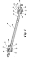
Figure 4 is a cross-sectional view through the steering link ofFigure 3 . - A wagon for containers is generally indicated at 10. It includes a pair of
bogies 11, having577mm diameter wheels 12, and adeck 13 which is carried onside bearers 14 of thebogies 11. The deck height is 730mm above the rail level. - Referring particularly to
Figure 2 , thebogie 11 includes aframe 15, which is suspended onwheel sets 16, byrespective suspensions 17. The frame is cranked at 18 to allow for a low position of theside bearers 14. -
Steering links 19 are provided to extend respectivefixed points 20 on theframe 15 and the respective axle boxes ofrespective wheel sets 16. - Each
steering link 19 can be extended and contracted in a controlled manner in response to longitudinal displacement of the associatedwheel 12 so as to simultaneously allow a degree of movement, but in a controlled fashion. - Thus, whilst a bogie is going round a curve on a rail, those wheels which are travelling on the inner part of the curve will tend to move in a sense to contract the
link 19, whilst those on the outer side of the curve will move in a sense to extend their associatedlink 19. It will be understood that there are links on each side of the bogie. - This arrangement enables the disadvantages that arise from using the smaller wheels, i.e. wheels of less that 600mm diameter, whilst avoiding the significant cost of fully steerable or self-steerable wheel sets.
- A particularly economic form of
steering link 19 is illustrated inFigures 3 and4 . Thesteering link 19 comprises a centralelongate link element 22 having T-shaped heads 23 fixed to its respective ends, andanchor portions 24, which telescopically house theheads 25 of themembers 23. - As can be clearly seen in
Figure 4 , eachanchor member 24 comprises aball joint 26 which is integrally connected to afirst housing member 27, which can be joined with asecond housing member 28, by means ofbolts 29 to form achamber 30 in which ahead 25 is received. Eachchamber 30 also contains acompression spring 31 and arigid cylinder 32 which is circumjacent thespring 31. - At the right hand end, the
compression spring 30 is mounted to act between thefirst housing member 27 and theend face 33 of thehead 25, whereas at the left hand end thespring 31 is located to act between thesecond housing member 28 annularrear face 34 of thehead 25. - It will readily be appreciated that on compression of the
link 19 telescopic contraction will take place in the righthand anchor member 24, whilst on extension of the link telescopic extension will take place in the lefthand anchor member 24. At all times these movements will take place by compressing therespective spring 31 and so they can be controlled. - It will be understood that the design is such that it has a very low component count and is very easy to assemble. Further springs of different rating can easily be put into their
respective chambers 30 so that tuning can take place as necessary. - The
sleeves 32 provide "hard stops" for therespective heads 25 so as to limit the degree of longitudinal movement that can occur for thewheels 12, for example under heavy braking.
Claims (9)
- A variable length steering link assembly for a bogie (11) characterised in that the assembly (19) includes an elongate link (22) having a generally T-shaped head (23) at each end and an anchor (24) for each end, wherein each anchor (24) defines an axially extending chamber (30) for slidably receiving a respective head (23) and a compression spring (31) wherein in one chamber (30) the spring (31) acts on the end face (32) of its associated head (23) and in the other chamber the spring acts on the back face of its associated head (23).
- A variable length steering link assembly as claimed in claim 1, wherein at least one anchor (24) includes a ball joint (36) for connecting to a part of the bogie (11).
- A variable length steering link assembly as claimed in claim 1 or claim 2 wherein each link (22) has a central element and two heads (23).
- A variable length steering link assembly as claimed in claim 1 wherein the anchors (24) are identical.
- A variable length steering link assembly as claimed in claim 1 including hard stops (32) for limiting the extension or contraction of the assembly.
- A variable length steering link assembly as claimed in claim 1 wherein at least one anchor (24) includes a ball joint (26) for connecting to a part of the bogie (11) and wherein the link (19) has a central element (22) and two heads (23).
- A variable length steering link assembly as claimed in claim 6 wherein the anchors (24) are identical.
- A variable length steering link assembly as claimed in any one of claims 1 to 4 and claims 6 or 7 including hard stops (32) for limiting the extension or contraction of the assembly.
- A container wagon (10) having at least a pair of bogies (11) having wheels (12) of diameters of less than 600mm, each bogie having a steering link (19) extending from its frame to a wheel set, for each wheel set wherein there are a pair of steering links (19) for each wheel set, one on each side of the bogie (11) characterised in that each link (19) is a variable length steering link assembly (19) as claimed in claim 1, wherein each steering link (19) is extendable and includes a pair of compression springs (31), one of which is compressed on extension of the link (19) and one of which is compressed on contraction of the link (19).
Applications Claiming Priority (2)
| Application Number | Priority Date | Filing Date | Title |
|---|---|---|---|
| US435507P | 2007-11-27 | 2007-11-27 | |
| GB0723150A GB0723150D0 (en) | 2007-11-27 | 2007-11-27 | Steering links |
Publications (3)
| Publication Number | Publication Date |
|---|---|
| EP2065284A2 EP2065284A2 (en) | 2009-06-03 |
| EP2065284A3 EP2065284A3 (en) | 2011-08-17 |
| EP2065284B1 true EP2065284B1 (en) | 2014-06-25 |
Family
ID=38926066
Family Applications (1)
| Application Number | Title | Priority Date | Filing Date |
|---|---|---|---|
| EP20080253768 Not-in-force EP2065284B1 (en) | 2007-11-27 | 2008-11-19 | Steering links for railway bogies |
Country Status (2)
| Country | Link |
|---|---|
| EP (1) | EP2065284B1 (en) |
| GB (1) | GB0723150D0 (en) |
Families Citing this family (1)
| Publication number | Priority date | Publication date | Assignee | Title |
|---|---|---|---|---|
| CN103707897B (en) * | 2013-12-31 | 2016-06-08 | 中国人民解放军国防科学技术大学 | The anti-of magnetic suspension train Extendible spacing sidewinders elastic boom |
Family Cites Families (7)
| Publication number | Priority date | Publication date | Assignee | Title |
|---|---|---|---|---|
| US562406A (en) * | 1896-06-23 | Equalizer for street-railway cars | ||
| US4151801A (en) * | 1975-07-08 | 1979-05-01 | South African Inventions Development Corporation | Self-steering railway truck |
| CA1194363A (en) * | 1982-08-06 | 1985-10-01 | Gloucester Railway Carriage And Wagon Co. Limited | Suspensions for railway vehicles |
| US4676172A (en) * | 1983-12-02 | 1987-06-30 | Standard Research And Design Corp. | Frameless radial truck |
| US5277127A (en) * | 1989-08-21 | 1994-01-11 | Sig Schweizerische Industrie Gesellschaft | Driven running gear with steerable individual units |
| CN1118397C (en) * | 1998-08-06 | 2003-08-20 | 赫伯特·谢费尔 | self-steering bogie |
| AU1173100A (en) * | 1998-11-26 | 2000-06-13 | Herbert Scheffel | Cross-anchor railway bogie |
-
2007
- 2007-11-27 GB GB0723150A patent/GB0723150D0/en not_active Ceased
-
2008
- 2008-11-19 EP EP20080253768 patent/EP2065284B1/en not_active Not-in-force
Also Published As
| Publication number | Publication date |
|---|---|
| GB0723150D0 (en) | 2008-01-02 |
| EP2065284A3 (en) | 2011-08-17 |
| EP2065284A2 (en) | 2009-06-03 |
Similar Documents
| Publication | Publication Date | Title |
|---|---|---|
| US6942230B1 (en) | Anti-rolling and anti-pitching system for a motor vehicle, and device for making the same | |
| CN100572176C (en) | A kind of hinged type self-discharging automobile chassis | |
| US8136455B2 (en) | Primary suspension device for a railway vehicle bogie | |
| US6129367A (en) | Axle suspension for rigid axles in vehicles | |
| US9428200B2 (en) | Device disposed in the roof area of two articulated vehicle parts for limiting the pitch movement of the vehicle parts relative to each other | |
| DE102008049761A1 (en) | Independent wheel suspension for multiple linkage of vehicle wheels, has transverse leaf spring running in vehicle transverse direction | |
| DE102014205632A1 (en) | Independent and rear suspension with independent wheel suspension for a vehicle and vehicle equipped accordingly | |
| EP1080953A1 (en) | Motor vehicle wheel suspension with a wheel guiding leaf spring | |
| WO2012022509A1 (en) | Pneumatic spring strut having a resilient piston bearing | |
| US6273002B1 (en) | Rail vehicle with a vertical support actuator | |
| US20090133599A1 (en) | Steering links | |
| DE102014205635A1 (en) | Independent and rear suspension with independent wheel suspension for a vehicle and vehicle equipped accordingly | |
| CA2336973C (en) | Bogie construction | |
| DE202014101432U1 (en) | Independent and rear suspension with independent wheel suspension for a vehicle and vehicle equipped accordingly | |
| EP2065284A2 (en) | Steering links for railway bogies | |
| WO1995026291A1 (en) | Anti-roll support for rail vehicles with a transverse tilting device | |
| WO2015159085A1 (en) | Suspension module for a rail vehicle | |
| DE19703701C2 (en) | Two-axle chassis for rail-bound transport systems | |
| EP0277929A1 (en) | Bogie arrangement for a railway vehicle | |
| EP2088049B1 (en) | Device for connecting the bogie of a railway vehicle to the bolster or to the vehicle underframe | |
| EP4275928A1 (en) | Chassis for a motor vehicle | |
| DE202015101117U1 (en) | Independent and rear suspension with independent wheel suspensions for one vehicle | |
| EP3992053B1 (en) | Bogie for a rail vehicle and rail vehicle with a bogie | |
| DE10321879B4 (en) | Independent wheel suspension with swiveling axle component | |
| CA2152378A1 (en) | Leaf spring for a rigid axle of a vehicle |
Legal Events
| Date | Code | Title | Description |
|---|---|---|---|
| PUAI | Public reference made under article 153(3) epc to a published international application that has entered the european phase |
Free format text: ORIGINAL CODE: 0009012 |
|
| AK | Designated contracting states |
Kind code of ref document: A2 Designated state(s): AT BE BG CH CY CZ DE DK EE ES FI FR GB GR HR HU IE IS IT LI LT LU LV MC MT NL NO PL PT RO SE SI SK TR |
|
| AX | Request for extension of the european patent |
Extension state: AL BA MK RS |
|
| PUAL | Search report despatched |
Free format text: ORIGINAL CODE: 0009013 |
|
| AK | Designated contracting states |
Kind code of ref document: A3 Designated state(s): AT BE BG CH CY CZ DE DK EE ES FI FR GB GR HR HU IE IS IT LI LT LU LV MC MT NL NO PL PT RO SE SI SK TR |
|
| AX | Request for extension of the european patent |
Extension state: AL BA MK RS |
|
| RIC1 | Information provided on ipc code assigned before grant |
Ipc: B61F 5/38 20060101ALI20110714BHEP Ipc: B61F 5/30 20060101AFI20110714BHEP |
|
| 17P | Request for examination filed |
Effective date: 20111220 |
|
| AKX | Designation fees paid |
Designated state(s): AT BE BG CH CY CZ DE DK EE ES FI FR GB GR HR HU IE IS IT LI LT LU LV MC MT NL NO PL PT RO SE SI SK TR |
|
| GRAP | Despatch of communication of intention to grant a patent |
Free format text: ORIGINAL CODE: EPIDOSNIGR1 |
|
| INTG | Intention to grant announced |
Effective date: 20140225 |
|
| GRAS | Grant fee paid |
Free format text: ORIGINAL CODE: EPIDOSNIGR3 |
|
| GRAA | (expected) grant |
Free format text: ORIGINAL CODE: 0009210 |
|
| AK | Designated contracting states |
Kind code of ref document: B1 Designated state(s): AT BE BG CH CY CZ DE DK EE ES FI FR GB GR HR HU IE IS IT LI LT LU LV MC MT NL NO PL PT RO SE SI SK TR |
|
| REG | Reference to a national code |
Ref country code: GB Ref legal event code: FG4D |
|
| REG | Reference to a national code |
Ref country code: CH Ref legal event code: EP |
|
| REG | Reference to a national code |
Ref country code: AT Ref legal event code: REF Ref document number: 674443 Country of ref document: AT Kind code of ref document: T Effective date: 20140715 |
|
| REG | Reference to a national code |
Ref country code: IE Ref legal event code: FG4D |
|
| REG | Reference to a national code |
Ref country code: DE Ref legal event code: R096 Ref document number: 602008032955 Country of ref document: DE Effective date: 20140807 |
|
| REG | Reference to a national code |
Ref country code: SE Ref legal event code: TRGR |
|
| PG25 | Lapsed in a contracting state [announced via postgrant information from national office to epo] |
Ref country code: FI Free format text: LAPSE BECAUSE OF FAILURE TO SUBMIT A TRANSLATION OF THE DESCRIPTION OR TO PAY THE FEE WITHIN THE PRESCRIBED TIME-LIMIT Effective date: 20140625 Ref country code: LT Free format text: LAPSE BECAUSE OF FAILURE TO SUBMIT A TRANSLATION OF THE DESCRIPTION OR TO PAY THE FEE WITHIN THE PRESCRIBED TIME-LIMIT Effective date: 20140625 Ref country code: CY Free format text: LAPSE BECAUSE OF FAILURE TO SUBMIT A TRANSLATION OF THE DESCRIPTION OR TO PAY THE FEE WITHIN THE PRESCRIBED TIME-LIMIT Effective date: 20140625 Ref country code: GR Free format text: LAPSE BECAUSE OF FAILURE TO SUBMIT A TRANSLATION OF THE DESCRIPTION OR TO PAY THE FEE WITHIN THE PRESCRIBED TIME-LIMIT Effective date: 20140926 Ref country code: NO Free format text: LAPSE BECAUSE OF FAILURE TO SUBMIT A TRANSLATION OF THE DESCRIPTION OR TO PAY THE FEE WITHIN THE PRESCRIBED TIME-LIMIT Effective date: 20140925 |
|
| REG | Reference to a national code |
Ref country code: AT Ref legal event code: MK05 Ref document number: 674443 Country of ref document: AT Kind code of ref document: T Effective date: 20140625 |
|
| REG | Reference to a national code |
Ref country code: NL Ref legal event code: VDEP Effective date: 20140625 |
|
| REG | Reference to a national code |
Ref country code: LT Ref legal event code: MG4D |
|
| PG25 | Lapsed in a contracting state [announced via postgrant information from national office to epo] |
Ref country code: LV Free format text: LAPSE BECAUSE OF FAILURE TO SUBMIT A TRANSLATION OF THE DESCRIPTION OR TO PAY THE FEE WITHIN THE PRESCRIBED TIME-LIMIT Effective date: 20140625 Ref country code: HR Free format text: LAPSE BECAUSE OF FAILURE TO SUBMIT A TRANSLATION OF THE DESCRIPTION OR TO PAY THE FEE WITHIN THE PRESCRIBED TIME-LIMIT Effective date: 20140625 |
|
| PG25 | Lapsed in a contracting state [announced via postgrant information from national office to epo] |
Ref country code: EE Free format text: LAPSE BECAUSE OF FAILURE TO SUBMIT A TRANSLATION OF THE DESCRIPTION OR TO PAY THE FEE WITHIN THE PRESCRIBED TIME-LIMIT Effective date: 20140625 Ref country code: PT Free format text: LAPSE BECAUSE OF FAILURE TO SUBMIT A TRANSLATION OF THE DESCRIPTION OR TO PAY THE FEE WITHIN THE PRESCRIBED TIME-LIMIT Effective date: 20141027 Ref country code: SK Free format text: LAPSE BECAUSE OF FAILURE TO SUBMIT A TRANSLATION OF THE DESCRIPTION OR TO PAY THE FEE WITHIN THE PRESCRIBED TIME-LIMIT Effective date: 20140625 Ref country code: CZ Free format text: LAPSE BECAUSE OF FAILURE TO SUBMIT A TRANSLATION OF THE DESCRIPTION OR TO PAY THE FEE WITHIN THE PRESCRIBED TIME-LIMIT Effective date: 20140625 Ref country code: RO Free format text: LAPSE BECAUSE OF FAILURE TO SUBMIT A TRANSLATION OF THE DESCRIPTION OR TO PAY THE FEE WITHIN THE PRESCRIBED TIME-LIMIT Effective date: 20140625 Ref country code: ES Free format text: LAPSE BECAUSE OF FAILURE TO SUBMIT A TRANSLATION OF THE DESCRIPTION OR TO PAY THE FEE WITHIN THE PRESCRIBED TIME-LIMIT Effective date: 20140625 |
|
| PG25 | Lapsed in a contracting state [announced via postgrant information from national office to epo] |
Ref country code: AT Free format text: LAPSE BECAUSE OF FAILURE TO SUBMIT A TRANSLATION OF THE DESCRIPTION OR TO PAY THE FEE WITHIN THE PRESCRIBED TIME-LIMIT Effective date: 20140625 Ref country code: PL Free format text: LAPSE BECAUSE OF FAILURE TO SUBMIT A TRANSLATION OF THE DESCRIPTION OR TO PAY THE FEE WITHIN THE PRESCRIBED TIME-LIMIT Effective date: 20140625 Ref country code: NL Free format text: LAPSE BECAUSE OF FAILURE TO SUBMIT A TRANSLATION OF THE DESCRIPTION OR TO PAY THE FEE WITHIN THE PRESCRIBED TIME-LIMIT Effective date: 20140625 Ref country code: IS Free format text: LAPSE BECAUSE OF FAILURE TO SUBMIT A TRANSLATION OF THE DESCRIPTION OR TO PAY THE FEE WITHIN THE PRESCRIBED TIME-LIMIT Effective date: 20141025 |
|
| REG | Reference to a national code |
Ref country code: DE Ref legal event code: R097 Ref document number: 602008032955 Country of ref document: DE |
|
| PG25 | Lapsed in a contracting state [announced via postgrant information from national office to epo] |
Ref country code: DK Free format text: LAPSE BECAUSE OF FAILURE TO SUBMIT A TRANSLATION OF THE DESCRIPTION OR TO PAY THE FEE WITHIN THE PRESCRIBED TIME-LIMIT Effective date: 20140625 Ref country code: IT Free format text: LAPSE BECAUSE OF FAILURE TO SUBMIT A TRANSLATION OF THE DESCRIPTION OR TO PAY THE FEE WITHIN THE PRESCRIBED TIME-LIMIT Effective date: 20140625 |
|
| PLBE | No opposition filed within time limit |
Free format text: ORIGINAL CODE: 0009261 |
|
| STAA | Information on the status of an ep patent application or granted ep patent |
Free format text: STATUS: NO OPPOSITION FILED WITHIN TIME LIMIT |
|
| 26N | No opposition filed |
Effective date: 20150326 |
|
| PG25 | Lapsed in a contracting state [announced via postgrant information from national office to epo] |
Ref country code: LU Free format text: LAPSE BECAUSE OF FAILURE TO SUBMIT A TRANSLATION OF THE DESCRIPTION OR TO PAY THE FEE WITHIN THE PRESCRIBED TIME-LIMIT Effective date: 20141119 Ref country code: MC Free format text: LAPSE BECAUSE OF FAILURE TO SUBMIT A TRANSLATION OF THE DESCRIPTION OR TO PAY THE FEE WITHIN THE PRESCRIBED TIME-LIMIT Effective date: 20140625 |
|
| REG | Reference to a national code |
Ref country code: CH Ref legal event code: PL |
|
| PG25 | Lapsed in a contracting state [announced via postgrant information from national office to epo] |
Ref country code: CH Free format text: LAPSE BECAUSE OF NON-PAYMENT OF DUE FEES Effective date: 20141130 Ref country code: LI Free format text: LAPSE BECAUSE OF NON-PAYMENT OF DUE FEES Effective date: 20141130 |
|
| REG | Reference to a national code |
Ref country code: IE Ref legal event code: MM4A |
|
| REG | Reference to a national code |
Ref country code: FR Ref legal event code: ST Effective date: 20150731 |
|
| PG25 | Lapsed in a contracting state [announced via postgrant information from national office to epo] |
Ref country code: IE Free format text: LAPSE BECAUSE OF NON-PAYMENT OF DUE FEES Effective date: 20141119 |
|
| PG25 | Lapsed in a contracting state [announced via postgrant information from national office to epo] |
Ref country code: SI Free format text: LAPSE BECAUSE OF FAILURE TO SUBMIT A TRANSLATION OF THE DESCRIPTION OR TO PAY THE FEE WITHIN THE PRESCRIBED TIME-LIMIT Effective date: 20140625 Ref country code: FR Free format text: LAPSE BECAUSE OF NON-PAYMENT OF DUE FEES Effective date: 20141201 |
|
| PG25 | Lapsed in a contracting state [announced via postgrant information from national office to epo] |
Ref country code: BG Free format text: LAPSE BECAUSE OF FAILURE TO SUBMIT A TRANSLATION OF THE DESCRIPTION OR TO PAY THE FEE WITHIN THE PRESCRIBED TIME-LIMIT Effective date: 20140625 |
|
| PG25 | Lapsed in a contracting state [announced via postgrant information from national office to epo] |
Ref country code: TR Free format text: LAPSE BECAUSE OF FAILURE TO SUBMIT A TRANSLATION OF THE DESCRIPTION OR TO PAY THE FEE WITHIN THE PRESCRIBED TIME-LIMIT Effective date: 20140625 Ref country code: BE Free format text: LAPSE BECAUSE OF FAILURE TO SUBMIT A TRANSLATION OF THE DESCRIPTION OR TO PAY THE FEE WITHIN THE PRESCRIBED TIME-LIMIT Effective date: 20140625 Ref country code: MT Free format text: LAPSE BECAUSE OF FAILURE TO SUBMIT A TRANSLATION OF THE DESCRIPTION OR TO PAY THE FEE WITHIN THE PRESCRIBED TIME-LIMIT Effective date: 20140625 Ref country code: HU Free format text: LAPSE BECAUSE OF FAILURE TO SUBMIT A TRANSLATION OF THE DESCRIPTION OR TO PAY THE FEE WITHIN THE PRESCRIBED TIME-LIMIT; INVALID AB INITIO Effective date: 20081119 |
|
| PGFP | Annual fee paid to national office [announced via postgrant information from national office to epo] |
Ref country code: GB Payment date: 20161014 Year of fee payment: 9 Ref country code: DE Payment date: 20161121 Year of fee payment: 9 |
|
| REG | Reference to a national code |
Ref country code: DE Ref legal event code: R119 Ref document number: 602008032955 Country of ref document: DE |
|
| REG | Reference to a national code |
Ref country code: SE Ref legal event code: EUG |
|
| GBPC | Gb: european patent ceased through non-payment of renewal fee |
Effective date: 20171119 |
|
| PG25 | Lapsed in a contracting state [announced via postgrant information from national office to epo] |
Ref country code: SE Free format text: LAPSE BECAUSE OF NON-PAYMENT OF DUE FEES Effective date: 20171120 |
|
| PG25 | Lapsed in a contracting state [announced via postgrant information from national office to epo] |
Ref country code: DE Free format text: LAPSE BECAUSE OF NON-PAYMENT OF DUE FEES Effective date: 20180602 |
|
| PG25 | Lapsed in a contracting state [announced via postgrant information from national office to epo] |
Ref country code: GB Free format text: LAPSE BECAUSE OF NON-PAYMENT OF DUE FEES Effective date: 20171119 |
|
| PGFP | Annual fee paid to national office [announced via postgrant information from national office to epo] |
Ref country code: SE Payment date: 20191227 Year of fee payment: 12 |
|
| P01 | Opt-out of the competence of the unified patent court (upc) registered |
Effective date: 20230530 |