EP2065265B1 - Device and method for folding an airbag - Google Patents
Device and method for folding an airbag Download PDFInfo
- Publication number
- EP2065265B1 EP2065265B1 EP07023916A EP07023916A EP2065265B1 EP 2065265 B1 EP2065265 B1 EP 2065265B1 EP 07023916 A EP07023916 A EP 07023916A EP 07023916 A EP07023916 A EP 07023916A EP 2065265 B1 EP2065265 B1 EP 2065265B1
- Authority
- EP
- European Patent Office
- Prior art keywords
- airbag
- blind
- stamp
- contour
- punch
- Prior art date
- Legal status (The legal status is an assumption and is not a legal conclusion. Google has not performed a legal analysis and makes no representation as to the accuracy of the status listed.)
- Not-in-force
Links
Images


Classifications
-
- B—PERFORMING OPERATIONS; TRANSPORTING
- B60—VEHICLES IN GENERAL
- B60R—VEHICLES, VEHICLE FITTINGS, OR VEHICLE PARTS, NOT OTHERWISE PROVIDED FOR
- B60R21/00—Arrangements or fittings on vehicles for protecting or preventing injuries to occupants or pedestrians in case of accidents or other traffic risks
- B60R21/02—Occupant safety arrangements or fittings, e.g. crash pads
- B60R21/16—Inflatable occupant restraints or confinements designed to inflate upon impact or impending impact, e.g. air bags
- B60R21/23—Inflatable members
- B60R21/237—Inflatable members characterised by the way they are folded
- B60R2021/2375—Folding devices
Definitions
- the present invention relates to an apparatus and method for producing a predetermined fold pattern in the envelope of an inflatable air bag, i. for folding an airbag.
- an air bag is compressed to a package size that allows the folded air bag to be mounted as part of an air bag module, such as a driver, passenger, or side airbag in a vehicle.
- the airbag must be folded so that it can unfold during inflation in the event of an accident quickly and without damaging the airbag shell in a desired manner.
- a device according to the preamble of claim 1 is made EP0 972 683 known.
- the invention has for its object to provide a method for generating a predetermined fold pattern in the shell of an inflatable airbag and a working device according to the method, which make it possible to fold an airbag as simple and fast as possible, so that this optimally and especially without Damage to the airbag cover can develop.
- the airbag By creating a plurality of parallel folds by pulling the airbag through the panel in the shell thereof, the airbag can then be compressed in the longitudinal direction of the pleats and e.g. into the housing of an air bag module.
- the envelope of the airbag does not chaotically deform and fold in the longitudinal direction of the folds during the subsequent compressing or compressing of the airbag , Rather, the fact that initially a plurality of mutually parallel folds is generated in the shell of the airbag, during the compression of the same an orderly or homogeneous folding of the airbag shell can be ensured so that the airbag can deploy optimally, thereby ultimately the risk of injury to the Vehicle occupants is minimized.
- the contour of the panel may, for example, have a multiplicity of rear and projections, which are arranged alternately with respect to one another.
- the generation of the predetermined fold pattern can be realized with parallel folds in the shell of the airbag.
- the back and projections may thus be similar to a comb around prongs or spaced apart teeth whose edges are flattened and preferably rounded so as to avoid damage to the air bag envelope when the air bag is pulled through the panel.
- the panel in a worktop, which is at least so large that the air bag to be folded on the worktop can be fully expanded.
- the airbag Before the airbag is pulled with the punch of the device through the aperture, the airbag can thus be placed or placed on the worktop in a fixed predetermined starting position in which he completely spans or covers the panel.
- the reproducibility of the fold pattern to be generated in the airbag envelope as well as the deployment characteristic of the airbag can be improved.
- the aperture may have a closed contour, whereby a predetermined fold pattern can be generated over the entire circumference of the airbag envelope.
- the airbag to be folded is an airbag which should only be able to spread in a certain direction, as is the case with a side airbag, for example, it may be sufficient to use an aperture with an open contour that only in the area in which the airbag interacts with the panel, a predetermined fold pattern is generated in the airbag shell.
- An aperture with an open contour may also prove advantageous in that the guide and the drive for the punch through the open area of the aperture to the outside, e.g. can be guided to a kind of slotted guide, which allows a relatively simple construction of the device.
- the punch has a tubular shape and also a counter-punch is provided, which is surrounded as a result of the advancing movement of the punch through the aperture of the latter.
- the punch inverts during its advancing movement through the aperture on the located on the other side of the diaphragm counter punch.
- the airbag is pulled through the baffle, changing its direction at the free tube end of the punch, and coming to rest between the outside of the counter punch and the inside of the tubular punch.
- a piston which is displaceable independently of the plunger through the diaphragm may be provided inside the plunger, to the free end of which the airbag to be folded is releasably attachable.
- this piston serves on the one hand for fastening the airbag and thus for generating a fixed predetermined starting position of the airbag.
- said piston is used to compress the air bag, after it has been drawn into the annulus between the counter punch and the tubular punch, within the annulus. For this purpose, the piston is pushed to reduce the annular space in the axial direction within the tubular punch through the aperture, wherein at the same time the counter punch is pulled back or pushed back by means of the piston to allow the reduction of the annular space.
- a cover plate may further be provided which is arranged above the worktop and at a distance from it is.
- the cover plate has above the aperture of the worktop on a recess to allow access of the punch and the piston displaceable therein to the aperture.
- the cover plate needs to be arranged only a few millimeters above the worktop, which makes it necessary to arrange the airbag spread flat in the space between the cover plate and the worktop. The operator of the device according to the invention is thus to some extent forced to spread the airbag neat and smooth in a fixed predetermined starting position, whereby the reproducibility of the wrinkle generation is further improved.
- the object underlying the invention is also achieved by the features of the independent claim relating to the method.
- the object underlying the invention is also achieved by the features of the independent claim relating to the method.
- an airbag is first spread on a worktop, which has a diaphragm which at least partially has such a contour that when pulling the airbag through the aperture in the airbag envelope of the airbag, a predetermined fold pattern is generated.
- the airbag is then pulled through the panel in the method according to the invention, whereby in the desired manner in the shell, the predetermined fold pattern is produced with a plurality of parallel folds.
- the airbag Although it would be possible to pull the air bag by hand through the aperture; however, in order to improve the reproducibility of wrinkling production and to automate the process, it is provided according to a preferred embodiment to pull the airbag through the panel by pushing a punch therethrough.
- the stamp can in this case in the manner described above have a tubular shape, so that during the advancing movement of the punch through the aperture of the airbag can be slipped over a counter punch.
- the device 10 has a horizontal working plate 14, in which a diaphragm 12 is formed, which may have a closed or open contour, as can be seen from the plan view according to section B-B.
- the panel 12 has a plurality of back and projections 36, 34 which are arranged alternately to each other and thus form a plurality of prongs or fingers.
- the rear and projections 36, 34 in this case have a rounded shape, so that in a sense results in a serpentine, meandering or wavy aperture contour.
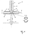
- a cover plate 18 is arranged, which has a recess 38 above the aperture 12 of the worktop 14. Between the countertop 14 and the cover plate 18, a gap only a few millimeters high is formed, in which an air bag 30 to be folded using the device 10 according to the invention is to be spread over the surface, as shown in FIG Fig. 1 is shown.
- the device 10 further comprises a tubular and preferably hollow cylindrical punch 16 which is positioned so that it can be pushed through the recess 38 of the cover plate 18 and the aperture 12 aligned with the aperture 12 from above.
- a piston 22 which is displaceable independently of the punch 16 through the recess 38 and the aperture 12, is provided which fits precisely in the punch 16 is arranged.
- the piston 22 is attached to a piston rod 40, by the actuation of the piston 22 can be moved within the punch 16.
- the piston 22 has a plurality of attachment recesses (not shown) which serve to secure the airbag 30 thereto. More specifically, the airbag 30 has a gas generator 24, which protruding from the air bag 30 mounting pin 28 (see Fig. 4 ), via which the airbag 30 can be secured in the aforementioned attachment recesses on the underside of the piston 22.
- the device 10 further comprises a cylindrical counter punch 20, which is movable from a located below the countertop 14 pressure member 26 in the direction of the work surface 14 and through the aperture 12 thereof.
- the counter punch 20 can be moved so far up until it comes with the air bag 30 and in particular with the gas generator 24 in abutment, so that the gas generator 24 on the one hand via the mounting pin 28 on the piston 22 and on the other hand by the counter punch 20 in his position is secured. It could basically be dispensed with the mounting pin 28 for securing the position.
- the counter punch 20 is moved by the pressure piece 26 and the aperture 12 up until it touches the underside of the airbag 30.
- the tubular punch 16 is moved through the recess 38 in the space between the cover plate 18 and the work surface 14 down, with the piston 22 initially does not move.
- the punch 16 then penetrates in its further feed movement in the aperture 12, it comes with its lower end to the shell of the airbag 30 in abutment, so that with continued advancing movement of the punch 16 through the aperture 12 of the air bag 30 through the aperture 12th is pulled through (see Fig. 2 ).
- the airbag 30 is deflected to a certain extent at the lower edge of the punch 16 and ultimately comes to rest in the annular space 42 between the tubular punch 16 and the counter punch 20.
- a predetermined fold pattern with folds 32 extending parallel to one another is generated in the envelope of the airbag 30 in the desired manner, the shape, size and distance of which depends on the contour of the panel 12 (please refer Fig. 4 ).
- the airbag envelope is, as it were, combed by means of the projections and recesses 34, 36 which define the contour of the panel 12, so that depending on the distance W (FIG. Fig. 4 ) of the projections and recesses 34, 36, the folds 32 a smaller (see, for example Fig. 4a ) or a larger distance W (see, for example Fig. 4c ) to each other.
- the airbag 30 When the airbag 30 is in the in Fig. 3 shown flaccid hanging down position, the airbag 30 can be compressed or pushed back in the longitudinal direction of the punch assembly 16, 20 by the piston 22 is moved by actuation of the piston rod 40 down. At the same time the counter punch 20 is withdrawn by the pressure piece 26, so that during the reduction of the annular space 42 and the concomitant compression of the air bag 30 is prevented by the counter punch 20 that when compressing the air bag 30 interlocking portions of the airbag 30 together or hook or to lie on top of each other. Thus, a homogeneous folding of the airbag sleeve 30 is ensured.
- the folded airbag 30 can be introduced into a ready-housing of an airbag module.
Abstract
Description
Die vorliegende Erfindung betrifft eine Vorrichtung sowie ein Verfahren zum Erzeugen eines vorbestimmten Faltenmusters in der Hülle eines aufblasbaren Luftsacks, d.h. zum Falten eines Luftsacks.The present invention relates to an apparatus and method for producing a predetermined fold pattern in the envelope of an inflatable air bag, i. for folding an airbag.
Üblicherweise wird ein Luftsack auf eine Packungsgröße komprimiert bzw. zusammengefaltet, die es gestattet, den gefalteten Luftsack als Teil eines Luftsackmoduls beispielsweise als Fahrer-, Beifahrer- oder Seitenairbag in einem Fahrzeug zu montieren. Hierbei muss der Luftsack so gefaltet werden, dass er sich beim Aufblasen im Falle eines Unfalls schnell und ohne Beschädigungen der Luftsackhülle in einer gewünschten Weise entfalten kann.Typically, an air bag is compressed to a package size that allows the folded air bag to be mounted as part of an air bag module, such as a driver, passenger, or side airbag in a vehicle. In this case, the airbag must be folded so that it can unfold during inflation in the event of an accident quickly and without damaging the airbag shell in a desired manner.
Eine Vorrichtung gemäβ dem Oberbegriff des Anspruch 1 ist aus
Der Erfindung liegt die Aufgabe zugrunde, ein Verfahren zum Erzeugen eines vorbestimmten Faltenmusters in der Hülle eines aufblasbaren Luftsacks sowie eine nach dem Verfahren arbeitende Vorrichtung zu schaffen, welche es ermöglichen, einen Luftsack möglichst einfach und schnell zusammenzufalten, so dass sich dieser optimal und insbesondere ohne Beschädigungen der Luftsackhülle entfalten kann.The invention has for its object to provide a method for generating a predetermined fold pattern in the shell of an inflatable airbag and a working device according to the method, which make it possible to fold an airbag as simple and fast as possible, so that this optimally and especially without Damage to the airbag cover can develop.
Die Lösung dieser Aufgabe erfolgt gemäß einem Aspekt der Erfindung durch die Merkmale des die Vorrichtung betreffenden Anspruchs 1 und insbesondere dadurch, dass eine Blende sowie ein durch die Blende hindurch verschiebbarer Stempel vorgesehen ist, wobei die Blende zumindest bereichsweise eine derart ausgebildete Kontur aufweist, dass in der Hülle eines von dem Stempel durch die Blende hindurch gezogenen Luftsacks ein vorbestimmtes Faltenmuster mit parallel zueinander verlaufenden Falten erzeugt werden kann. Sofern im Rahmen der vorliegenden Erfindung der Begriff "Blende" verwendet wird, so ist hierunter entsprechend einer optischen Blende eine durch eine Berandung bzw. Kontur zumindest teilweise begrenzte Öffnung oder Aussparung zu verstehen, welche den durch sie hindurch gezogenen Luftsack beim Hindurchziehen bündelt bzw. einschnürt.The solution of this object is achieved according to an aspect of the invention by the features of the device related claim 1 and in particular by the fact that a diaphragm and a slidable through the aperture punch is provided, wherein the aperture at least partially has such a contour formed that in the shell one of the stamp through the aperture pulled through the airbag a predetermined fold pattern can be generated with parallel folds. If the term "aperture" is used in the context of the present invention, this is to be understood as meaning an aperture defined by a boundary or contour at least partially, which bundles or constricts the airbag pulled through it when pulling through it ,
Dadurch, dass durch das Hindurchziehen des Luftsacks durch die Blende in der Hülle desselben eine Vielzahl parallel zueinander verlaufender Falten erzeugt wird, lässt sich dann anschließend der Luftsack in Längsrichtung der Falten komprimieren und z.B. in das Gehäuse eines Luftsackmoduls einbringen. Indem mit der erfindungsgemäßen Vorrichtung zunächst ein vorbestimmtes Faltenmuster mit parallel zueinander verlaufenden Falten in der Hülle des Luftsacks erzeugt wird, kann sichergestellt werden, dass sich die Hülle des Luftsacks während des anschließenden Komprimierens bzw. Zusammendrückens des Luftsacks in Längsrichtung der Falten nicht chaotisch verformt und verfaltet. Vielmehr kann dadurch, dass zunächst eine Vielzahl parallel zueinander verlaufender Falten in der Hülle des Luftsacks erzeugt wird, während des Komprimierens desselben ein geordnetes bzw. homogenes Zusammenfalten der Luftsackhülle sichergestellt werden, so dass sich der Luftsack optimal entfalten kann, wodurch letztendlich das Verletzungsrisiko für die Fahrzeuginsassen minimiert wird.By creating a plurality of parallel folds by pulling the airbag through the panel in the shell thereof, the airbag can then be compressed in the longitudinal direction of the pleats and e.g. into the housing of an air bag module. By initially creating a predetermined fold pattern with parallel folds in the envelope of the airbag with the device according to the invention, it can be ensured that the envelope of the airbag does not chaotically deform and fold in the longitudinal direction of the folds during the subsequent compressing or compressing of the airbag , Rather, the fact that initially a plurality of mutually parallel folds is generated in the shell of the airbag, during the compression of the same an orderly or homogeneous folding of the airbag shell can be ensured so that the airbag can deploy optimally, thereby ultimately the risk of injury to the Vehicle occupants is minimized.
Bevorzugte Ausführungsformen der erfindungsgemäßen Vorrichtung ergeben sich aus den abhängigen Ansprüchen, der Beschreibung sowie den Zeichnungen.Preferred embodiments of the device according to the invention will become apparent from the dependent claims, the description and the drawings.
So kann die Kontur der Blende gemäß einer Ausführungsform beispielsweise eine Vielzahl an Rück- und Vorsprüngen aufweisen, welche abwechselnd zueinander angeordnet sind. Hierdurch kann in der gewünschten Weise die Erzeugung des vorbestimmten Faltenmusters mit parallel zueinander verlaufenden Falten in der Hülle des Luftsacks realisiert werden. Wenn der Luftsack durch die Vorschubbewegung des Stempels der Vorrichtung durch die Blende hindurch gezogen wird, wird die Luftsackhülle gewissermaßen durch die Rück- und Vorsprünge in der Kontur der Blende gekämmt, so dass die Hülle in Falten gelegt wird.Thus, according to one embodiment, the contour of the panel may, for example, have a multiplicity of rear and projections, which are arranged alternately with respect to one another. In this way, in the desired manner, the generation of the predetermined fold pattern can be realized with parallel folds in the shell of the airbag. When the airbag is pulled through the aperture by the advancing movement of the punch of the device, the airbag envelope is, as it were, combed through the rear and protrusions in the contour of the aperture, so that the envelope is wrinkled.
Bei den Rück- und Vorsprüngen kann es sich somit ähnlich wie bei einem Kamm um Zinken oder beabstandet zueinander angeordnete Zähne handeln, deren Kanten abgeflacht und vorzugsweise abgerundet sind, um bei dem Hindurchziehen des Luftsacks durch die Blende Beschädigungen der Luftsackhülle zu vermeiden.The back and projections may thus be similar to a comb around prongs or spaced apart teeth whose edges are flattened and preferably rounded so as to avoid damage to the air bag envelope when the air bag is pulled through the panel.
Insbesondere aus Gründen der Qualitätssicherung und -kontrolle kann es sich als vorteilhaft erweisen, die Blende in einer Arbeitsplatte auszubilden, welche zumindest so groß ist, dass der zu faltende Luftsack auf der Arbeitsplatte vollständig ausgebreitet werden kann. Bevor der Luftsack mit dem Stempel der Vorrichtung durch die Blende hindurch gezogen wird, kann der Luftsack somit auf der Arbeitsplatte in eine fest vorgegebene Ausgangslage gebracht bzw. gelegt werden, in welcher er die Blende vollständig überspannt bzw. überdeckt. Hierdurch kann die Reproduzierbarkeit des zu erzeugenden Faltenmusters in der Luftsackhülle sowie die Entfaltungscharakteristik des Luftsacks verbessert werden.In particular, for reasons of quality assurance and control, it may prove advantageous to form the panel in a worktop, which is at least so large that the air bag to be folded on the worktop can be fully expanded. Before the airbag is pulled with the punch of the device through the aperture, the airbag can thus be placed or placed on the worktop in a fixed predetermined starting position in which he completely spans or covers the panel. As a result, the reproducibility of the fold pattern to be generated in the airbag envelope as well as the deployment characteristic of the airbag can be improved.
Gemäß einer weiteren Ausführungsform kann die Blende eine geschlossene Kontur aufweisen, wodurch sich über den gesamten Umfang der Luftsackhülle hinweg ein vorbestimmtes Faltenmuster erzeugen lässt. Diese Ausführungsform erweist sich insbesondere dann als vorteilhaft, wenn - wie beispielsweise bei einem Fahrerairbag - besonderer Wert darauf gelegt wird, dass sich der Luftsack über seinen Umfang hinweg gleichmäßig ausbreiten können soll.According to a further embodiment, the aperture may have a closed contour, whereby a predetermined fold pattern can be generated over the entire circumference of the airbag envelope. These Embodiment proves to be particularly advantageous if - as for example in a driver's airbag - special emphasis is placed on the fact that the airbag should be able to spread evenly over its circumference.
Wenn es sich hingegen bei dem zu faltenden Luftsack um einen Luftsack handelt, welcher sich nur in eine bestimmte Richtung ausbreiten können soll, wie dies beispielsweise bei einem Seitenairbag der Fall ist, so kann es ausreichen, eine Blende mit einer offenen Kontur zu verwenden, so dass nur in dem Bereich, in dem der Luftsack mit der Blende zusammenwirkt, ein vorbestimmtes Faltenmuster in der Luftsackhülle erzeugt wird. Eine Blende mit einer offenen Kontur kann sich ferner dahingehend als vorteilhaft erweisen, dass die Führung sowie der Antrieb für den Stempel durch den offenen Bereich der Blende nach außen z.B. zu einer Art Kulissenführung hingeführt werden kann, was einen verhältnismäßig einfachen Aufbau der Vorrichtung ermöglicht.If, on the other hand, the airbag to be folded is an airbag which should only be able to spread in a certain direction, as is the case with a side airbag, for example, it may be sufficient to use an aperture with an open contour that only in the area in which the airbag interacts with the panel, a predetermined fold pattern is generated in the airbag shell. An aperture with an open contour may also prove advantageous in that the guide and the drive for the punch through the open area of the aperture to the outside, e.g. can be guided to a kind of slotted guide, which allows a relatively simple construction of the device.
Um eine hinterschnittfreie Faltengebung in der Hülle des Luftsacks sicherzustellen, ist gemäß einer weiteren Ausführungsform vorgesehen, dass der Stempel eine rohrförmige Gestalt aufweist und ferner ein Gegenstempel vorgesehen ist, welcher infolge der Vorschubbewegung des Stempels durch die Blende von diesem umgeben wird. Insbesondere stülpt sich der Stempel während seiner Vorschubbewegung durch die Blende hindurch über den auf der anderen Seite der Blende befindlichen Gegenstempel. Während der Vorschubbewegung des Stempels durch die Blende hindurch wird der Luftsack durch die Blende hindurch gezogen, wobei er an dem freien Rohrende des Stempels eine Richtungsänderung erfährt und zwischen der Außenseite des Gegenstempels und der Innenseite des rohrförmigen Stempels zu liegen kommt. Zwischen dem rohrförmigen Stempel und dem kleineren Gegenstempel entsteht somit ein als Faltraum oder Faltkanal dienender Ringraum, in welchem die Luftsackhülle anschließend längs der zuvor erzeugten Falten komprimiert bzw. zusammengedrückt werden kann. Die dadurch entstehende ringförmige Faltung des Luftsacks ermöglicht ein ungehindertes radiales und axiales Entfalten der Luftsackhülle, da einander gegenüberliegende Bereiche der Luftsackhülle durch den Gegenstempel voneinander getrennt bzw. auf Abstand gehalten sind und sich somit während des Zusammendrückens nicht übereinander legen können.In order to ensure an undercut-free wrinkling in the shell of the airbag is provided according to a further embodiment, that the punch has a tubular shape and also a counter-punch is provided, which is surrounded as a result of the advancing movement of the punch through the aperture of the latter. In particular, the punch inverts during its advancing movement through the aperture on the located on the other side of the diaphragm counter punch. During the advancing movement of the punch through the baffle, the airbag is pulled through the baffle, changing its direction at the free tube end of the punch, and coming to rest between the outside of the counter punch and the inside of the tubular punch. Between the tubular punch and the smaller counter punch thus arises as a folding space or folding channel serving annular space, in which the airbag sheath can then be compressed or compressed along the previously generated folds. The resulting annular folding of the airbag allows unimpeded radial and axial deployment of the airbag shell, as opposed areas of the airbag shell are separated from each other by the counter punch or kept at a distance and thus can not overlap during compression.
Zwar gelangt der Luftsack, wenn er mit dem rohrförmigen Stempel durch die Blende hindurch gezogen wird, unweigerlich mit dem Kopf des Gegenstempels in Anlage; um jedoch die Reproduzierbarkeit der Faltenbildung noch weiter zu verbessern, kann gemäß einer weiteren Ausführungsform innerhalb des Stempels ein unabhängig von dem Stempel durch die Blende verschiebbarer Kolben vorgesehen sein, an dessen freien Ende der zu faltende Luftsack lösbar anbringbar ist. Wie bereits erwähnt, dient dieser Kolben zum einen zur Befestigung des Luftsacks und somit zur Erzeugung einer fest vorgegebenen Ausgangslage des Luftsacks. Darüber hinaus dient der genannte Kolben dazu, den Luftsack, nachdem dieser in den Ringraum zwischen dem Gegenstempel und dem rohrförmigen Stempel gezogen wurde, innerhalb des Ringraums zu komprimieren. Hierzu wird der Kolben zur Verkleinerung des Ringraums in axialer Richtung innerhalb des rohrförmigen Stempels durch die Blende hindurch geschoben, wobei gleichzeitig der Gegenstempel zurück gezogen bzw. mittels des Kolbens zurückgedrückt wird, um die Verkleinerung des Ringraums zu ermöglichen.Although the air bag, when it is pulled through the aperture with the tubular punch, inevitably comes into contact with the head of the counter punch; However, in order to improve the reproducibility of wrinkling even further, according to a further embodiment, a piston which is displaceable independently of the plunger through the diaphragm may be provided inside the plunger, to the free end of which the airbag to be folded is releasably attachable. As already mentioned, this piston serves on the one hand for fastening the airbag and thus for generating a fixed predetermined starting position of the airbag. In addition, said piston is used to compress the air bag, after it has been drawn into the annulus between the counter punch and the tubular punch, within the annulus. For this purpose, the piston is pushed to reduce the annular space in the axial direction within the tubular punch through the aperture, wherein at the same time the counter punch is pulled back or pushed back by means of the piston to allow the reduction of the annular space.
Um die Reproduzierbarkeit der Faltenerzeugung in der Luftsackhülle noch weiter zu verbessern, kann ferner eine Abdeckplatte vorgesehen sein, welche oberhalb der Arbeitsplatte und beabstandet zu derselben angeordnet ist. Die Abdeckplatte weist oberhalb der Blende der Arbeitsplatte eine Aussparung auf, um den Zugang des Stempels sowie des darin verschiebbaren Kolbens zu der Blende zu ermöglichen. Die Abdeckplatte braucht dabei nur wenige Millimeter oberhalb der Arbeitsplatte angeordnet zu sein, was es erforderlich macht, den Luftsack flach ausgebreitet in dem Zwischenraum zwischen der Abdeckplatte und der Arbeitsplatte anzuordnen. Die Bedienperson der erfindungsgemäßen Vorrichtung wird somit gewissermaßen dazu gezwungen, den Luftsack ordentlich und glatt in eine fest vorgegebene Ausgangslage auszubreiten, wodurch die Reproduzierbarkeit der Faltenerzeugung weiter verbessert wird.In order to further improve the reproducibility of the generation of wrinkles in the airbag sheath, a cover plate may further be provided which is arranged above the worktop and at a distance from it is. The cover plate has above the aperture of the worktop on a recess to allow access of the punch and the piston displaceable therein to the aperture. The cover plate needs to be arranged only a few millimeters above the worktop, which makes it necessary to arrange the airbag spread flat in the space between the cover plate and the worktop. The operator of the device according to the invention is thus to some extent forced to spread the airbag neat and smooth in a fixed predetermined starting position, whereby the reproducibility of the wrinkle generation is further improved.
Gemäß einem weiteren Aspekt wird die der Erfindung zugrunde liegende Aufgabe außerdem durch die Merkmale des das Verfahren betreffenden unabhängigen Anspruchs gelöst. In Bezug auf das erfindungsgemäße Verfahren sei an dieser Stelle erwähnt, dass sich sämtliche zuvor unter Bezugnahme auf die erfindungsgemäße Vorrichtung beschriebenen Merkmale in entsprechender Weise auf das erfindungsgemäße Verfahren übertragen lassen.According to a further aspect, the object underlying the invention is also achieved by the features of the independent claim relating to the method. With regard to the method according to the invention, it should be mentioned at this point that all the features described above with reference to the device according to the invention can be correspondingly transferred to the method according to the invention.
Bei dem erfindungsgemäßen Verfahren wird zunächst ein Luftsack auf einer Arbeitsplatte ausgebreitet, welche eine Blende aufweist, die zumindest bereichsweise eine derart ausgebildete Kontur aufweist, dass beim Hindurchziehen des Luftsacks durch die Blende in der Luftsackhülle des Luftsacks ein vorbestimmtes Faltenmusters erzeugt wird. Nachdem der Luftsack die Blende überdeckend auf der Arbeitsplatte angeordnet wurde, wird der Luftsack bei dem erfindungsgemäßen Verfahren anschließend durch die Blende hindurch gezogen, wodurch in der gewünschten Weise in der Hülle das vorbestimmte Faltenmuster mit einer Vielzahl von parallel zueinander verlaufenden Falten erzeugt wird.In the method according to the invention, an airbag is first spread on a worktop, which has a diaphragm which at least partially has such a contour that when pulling the airbag through the aperture in the airbag envelope of the airbag, a predetermined fold pattern is generated. After the airbag has been placed covering the panel on the worktop, the airbag is then pulled through the panel in the method according to the invention, whereby in the desired manner in the shell, the predetermined fold pattern is produced with a plurality of parallel folds.
Zwar wäre es möglich, den Luftsack von Hand durch die Blende hindurch zu ziehen; um jedoch die Reproduzierbarkeit der Faltenerzeugung zu verbessern und das Verfahren zu automatisieren, ist gemäß einer bevorzugten Ausführungsform vorgesehen, den Luftsack durch die Blende zu ziehen, indem ein Stempel durch dieselbe hindurch geschoben wird. Der Stempel kann hierbei in der voran beschriebenen Art und Weise eine rohrförmige Gestalt aufweisen, so dass während der Vorschubbewegung des Stempels durch die Blende der Luftsack über einen Gegenstempel gestülpt werden kann.Although it would be possible to pull the air bag by hand through the aperture; however, in order to improve the reproducibility of wrinkling production and to automate the process, it is provided according to a preferred embodiment to pull the airbag through the panel by pushing a punch therethrough. The stamp can in this case in the manner described above have a tubular shape, so that during the advancing movement of the punch through the aperture of the airbag can be slipped over a counter punch.
Weitere vorteilhafte Ausführungsformen des erfindungsgemäßen Verfahrens ergeben sich aus den abhängigen Ansprüchen, der Beschreibung der erfindungsgemäßen Vorrichtung, der nachfolgenden Figurenbeschreibung sowie den Zeichnungen.Further advantageous embodiments of the method according to the invention will become apparent from the dependent claims, the description of the device according to the invention, the following description of the figures and the drawings.
Im Folgenden wird die vorliegende Erfindung rein beispielhaft anhand eines Ausführungsbeispiels unter Bezugnahme auf die beigefügten Figuren beschrieben, wobei:
- Fig. 1
- eine Schnittansicht durch die erfindungsgemäße Vorrichtung in einer Ausgangsstellung zeigt;
- Fig. 2
- eine Schnittansicht durch die erfindungsgemäße Vorrichtung in einer Arbeitsstellung zeigt;
- Fig. 3
- eine Schnittansicht durch die erfindungsgemäße Vorrichtung in einer weiteren Arbeitsstellung zeigt; und
- Fig. 4a - 4c
- drei unter Verwendung unterschiedlicher Blenden gefaltete Luftsäcke zeigt.
- Fig. 1
- shows a sectional view through the device according to the invention in a starting position;
- Fig. 2
- shows a sectional view through the device according to the invention in a working position;
- Fig. 3
- shows a sectional view through the device according to the invention in a further working position; and
- Fig. 4a - 4c
- shows three air bags folded using different panels.
Zunächst wird unter Bezugnahme auf die
Die erfindungsgemäße Vorrichtung 10 weist eine horizontale Arbeitsplatte 14 auf, in der eine Blende 12 ausgebildet ist, welche eine geschlossene oder offene Kontur aufweisen kann, wie sich dies der Draufsicht gemäß Schnitt B-B entnehmen lässt. In der dargestellten Ausführungsform weist die Blende 12 eine Vielzahl von Rück- und Vorsprüngen 36, 34 auf, welche abwechselnd zueinander angeordnet sind und somit eine Vielzahl von Zinken oder Fingern bilden. Die Rück- und Vorsprünge 36, 34 weisen dabei eine abgerundete Gestalt auf, so dass sich gewissermaßen eine serpentinenförmige, mäandernde bzw. wellenförmige Blendenkontur ergibt.The
Oberhalb und beabstandet zu der Arbeitsplatte 14 ist eine Abdeckplatte 18 angeordnet, welche oberhalb der Blende 12 der Arbeitsplatte 14 eine Aussparung 38 aufweist. Zwischen der Arbeitsplatte 14 und der Abdeckplatte 18 ist ein nur wenige Millimeter hoher Zwischenraum gebildet, in welchem ein unter Verwendung der erfindungsgemäßen Vorrichtung 10 zu faltender Luftsack 30 flächig auszubreiten ist, wie dies in der
Die erfindungsgemäße Vorrichtung 10 weist ferner einen rohrförmigen und vorzugsweise hohlzylindrischen Stempel 16 auf, welcher derart positioniert ist, dass er durch die Aussparung 38 der Abdeckplatte 18 und die mit der Aussparung 38 fluchtende Blende 12 von oben hindurch geschoben werden kann. Innerhalb des rohrförmigen Stempels 16 ist ein unabhängig von dem Stempel 16 durch die Aussparung 38 und die Blende 12 verschiebbarer Kolben 22 vorgesehen, der passgenau in dem Stempel 16 angeordnet ist. Der Kolben 22 ist dabei an einer Kolbenstange 40 befestigt, durch deren Betätigung der Kolben 22 innerhalb des Stempels 16 verschoben werden kann. An der Unterseite weist der Kolben 22 mehrere Befestigungsausnehmungen (nicht dargestellt) auf, welche dazu dienen, den Luftsack 30 daran zu befestigen. Genauer gesagt weist der Luftsack 30 einen Gasgenerator 24 auf, welcher aus dem Luftsack 30 herausragende Befestigungszapfen 28 (siehe
Zusätzlich zu dem Stempel 16 weist die erfindungsgemäße Vorrichtung 10 ferner einen zylindrischen Gegenstempel 20 auf, welcher aus einem unterhalb der Arbeitsplatte 14 befindlichen Druckstück 26 in Richtung der Arbeitsplatte 14 und durch die Blende 12 derselben verfahrbar ist. Der Gegenstempel 20 lässt sich dabei so weit nach oben verfahren, bis er mit dem Luftsack 30 und insbesondere mit dem Gasgenerator 24 in Anlage gelangt, so dass der Gasgenerator 24 zum einen über die Befestigungszapfen 28 an dem Kolben 22 und andererseits durch den Gegenstempel 20 in seiner Lage gesichert ist. Es könnte grundsätzlich auch auf die Befestigungszapfen 28 zur Lagesicherung verzichtet werden.In addition to the
Im Folgenden werden nun die Arbeitsweise der erfindungsgemäßen Vorrichtung 10 sowie das erfindungsgemäße Verfahren zum Erzeugen eines vorbestimmten Faltenmusters in der Hülle des aufblasbaren Luftsacks 30 erläutert.The mode of operation of the
In der Ausgangsstellung der Vorrichtung 10 gemäß der
Anschließend wird der Gegenstempel 20 durch das Druckstück 26 und die Blende 12 soweit nach oben verfahren, bis er die Unterseite des Luftsacks 30 berührt. Danach wird der rohrförmige Stempel 16 durch die Aussparung 38 in den Zwischenraum zwischen der Abdeckplatte 18 und der Arbeitsplatte 14 nach unten verfahren, wobei sich der Kolben 22 zunächst nicht bewegt. Kurz bevor der Stempel 16 dann bei seiner weiteren Vorschubbewegung in die Blende 12 eindringt, gelangt er mit seinem unteren Ende an der Hülle des Luftsacks 30 in Anlage, so dass bei fortgesetzter Vorschubbewegung des Stempels 16 durch die Blende 12 der Luftsack 30 durch die Blende 12 hindurch gezogen wird (siehe
Infolge des Hindurchziehens des Luftsacks 30 durch die Blende 12 wird in der Hülle des Luftsacks 30 in der gewünschten Weise ein vorbestimmtes Faltenmuster mit parallel zueinander verlaufenden Falten 32 erzeugt, deren Form, Größe und Abstand von der Kontur der Blende 12 abhängt (siehe
Wenn der Stempel 16 soweit durch die Blende 12 vorgeschoben ist, dass er an dem Druckstück 26 anliegt, ist der Luftsack 30 infolge der Vorschubbewegung des Stempels 16 vollständig durch die Blende 12 hindurch gezogen worden, so dass sich der Luftsack 30 vollständig in dem Ringraum 42 befindet, in welchem er von dem Gasgenerator 24 schlaff nach unten hängt. Durch den Gegenstempel 20 wird dabei verhindert, dass sich einander gegenüberliegende Abschnitte des Luftsacks 30 gegenseitig berühren, während der Luftsack 30 infolge der Vorschubbewegung des Stempels 16 in den von dem Stempel 16 gebildeten Innenraum hineingezogen wird, wodurch beim im Folgenden beschriebenen Zusammendrücken des Luftsacks 30 eine hinterschnittfreie Faltung erreicht werden kann.When the
Wenn sich der Luftsack 30 in der in
Nachdem der Luftsack 30 infolge der Vorschubbewegung des Kolbens 22 und der damit einhergehenden Verkleinerung des Ringraums 42 zusammengedrückt und dabei homogen gefaltet wurde, kann der gefaltete Luftsack 30 in ein bereitstehendes Gehäuse eines Luftsackmoduls eingebracht werden.After the
- 1010
- Vorrichtungcontraption
- 1212
- Blendecover
- 1414
- Arbeitsplattecountertop
- 1616
- Stempelstamp
- 1818
- Abdeckplattecover
- 2020
- Gegenstempelcounterpunch
- 2222
- Kolbenpiston
- 2424
- Gasgeneratorinflator
- 2626
- DruckstückPressure piece
- 2828
- Befestigungszapfenfastening pins
- 3030
- Luftsackair bag
- 3232
- Faltenwrinkles
- 3434
- Vorsprung, ZinkenProjection, tines
- 3636
- Rücksprungreturn
- 3838
- Aussparungrecess
- 4040
- Kolbenstangepiston rod
- 4242
- Ringraumannulus
- WW
- Abstand von 34Distance of 34
Claims (12)
- Device for folding an inflatable airbag (30), comprising
a blind (12); and
a stamp (16) displaceable through the blind (12),
characterized in that the blind (12) includes a contour at least in regions, the contour configured such that a predetermined fold pattern with parallel folds (32) can be generated in the sleeve of an airbag (30) pulled through the blind (12) by the stamp (16). - Device according to claim 1,
characterized in that the contour of the blind (12) includes a plurality of recesses and projections (36, 34) arranged in an alternate manner. - Device according to claim 1 or 2,
characterized in that the contour of the blind (12) comprises a plurality of teeth, whose edges are preferably rounded. - Device according to at least one of the preceding claims,
characterized in that the blind (12) is formed in a work plate (14), which is at least large enough that the airbag (30) to be folded is completely spreadable thereon. - Device according to at least one of the preceding claims,
characterized in that the blind (12) comprises a closed contour. - Device according to one of the claims 1 to 4,
characterized in that the blind (12) comprises an open contour. - Device according to at least one of the preceding claims,
characterized in that the stamp (16) has a tubular shape and further a counter stamp (20) is provided, wherein the stamp (16) and the counter stamp (20) are movable relative to each other and limit a space (42) for the air bag sleeve in a relative position. - Device according to at least one of the preceding claims,
characterized in that within the stamp (16) a piston (22) is provided, slidable through the blind (12) independently of the stamp (16) whereat the airbag (30) to be folded can be attached releasable. - Device according to at least one of the preceding claims,
characterized in that further a cover plate (18) is provided, disposed above the work plate (14) spaced apart and comprising a recess above the blind (12) of the work plate (14). - Method for folding an inflatable airbag (30), comprising the steps:spreading the airbag (30) on a work plate (14) comprising a blind (12), that includes a contour at least in regions, the contour configured such that a predetermined fold pattern (32) is generated in the sleeve of the airbag (30) when pulling the airbag (30) through the blind (12); andpulling the airbag (30) through the blind (12).
- Method according to claim 10,
characterized in that the airbag (30) is pulled through the blind (12) by pushing a stamp (16) through the blind (12). - Method according to claim 10 or 11,
characterized in that during the movement of the stamp (16) through the blind (12) the airbag (30) is put over a counter stamp (20).
Priority Applications (4)
| Application Number | Priority Date | Filing Date | Title |
|---|---|---|---|
| DE502007002833T DE502007002833D1 (en) | 2007-11-27 | 2007-11-27 | Device and method for folding an airbag |
| EP07023916A EP2065265B1 (en) | 2007-11-27 | 2007-11-27 | Device and method for folding an airbag |
| AT07023916T ATE457247T1 (en) | 2007-11-27 | 2007-11-27 | DEVICE AND METHOD FOR FOLDING AN AIR BAG |
| PCT/EP2008/006048 WO2009068120A1 (en) | 2007-11-27 | 2008-07-23 | Device and method for folding an airbag |
Applications Claiming Priority (1)
| Application Number | Priority Date | Filing Date | Title |
|---|---|---|---|
| EP07023916A EP2065265B1 (en) | 2007-11-27 | 2007-11-27 | Device and method for folding an airbag |
Publications (2)
| Publication Number | Publication Date |
|---|---|
| EP2065265A1 EP2065265A1 (en) | 2009-06-03 |
| EP2065265B1 true EP2065265B1 (en) | 2010-02-10 |
Family
ID=39190327
Family Applications (1)
| Application Number | Title | Priority Date | Filing Date |
|---|---|---|---|
| EP07023916A Not-in-force EP2065265B1 (en) | 2007-11-27 | 2007-11-27 | Device and method for folding an airbag |
Country Status (4)
| Country | Link |
|---|---|
| EP (1) | EP2065265B1 (en) |
| AT (1) | ATE457247T1 (en) |
| DE (1) | DE502007002833D1 (en) |
| WO (1) | WO2009068120A1 (en) |
Families Citing this family (1)
| Publication number | Priority date | Publication date | Assignee | Title |
|---|---|---|---|---|
| EP2515887B1 (en) | 2009-12-22 | 2018-06-06 | UCB Biopharma SPRL | Polyvinylpyrrolidone for the stabilization of a solid dispersion of the non-crystalline form of rotigotine |
Family Cites Families (5)
| Publication number | Priority date | Publication date | Assignee | Title |
|---|---|---|---|---|
| DE19831613A1 (en) * | 1998-07-14 | 2000-01-20 | Delphi Automotive Systems Gmbh | Method and device for folding an inflatable air bag |
| CA2339160C (en) * | 1998-09-14 | 2005-01-25 | Breed Automotive Technology, Inc. | Method and apparatus for folding an airbag |
| WO2001076917A1 (en) * | 2000-04-11 | 2001-10-18 | Nihon Plast Co.,Ltd. | Method and device for folding up air bag, and air bag |
| DE102004028048A1 (en) * | 2004-06-09 | 2005-12-29 | Trw Automotive Safety Systems Gmbh | Folding method for gas bag, involves pushing ring-shaped outer region formed on gas bag, towards base after being bent at approximately 90 degrees so that outer region may surround central region |
| US7090248B2 (en) * | 2004-06-04 | 2006-08-15 | Trw Vehicle Safety Systems Inc. | Air bag and a method of folding the air bag |
-
2007
- 2007-11-27 DE DE502007002833T patent/DE502007002833D1/en active Active
- 2007-11-27 AT AT07023916T patent/ATE457247T1/en active
- 2007-11-27 EP EP07023916A patent/EP2065265B1/en not_active Not-in-force
-
2008
- 2008-07-23 WO PCT/EP2008/006048 patent/WO2009068120A1/en active Application Filing
Also Published As
| Publication number | Publication date |
|---|---|
| ATE457247T1 (en) | 2010-02-15 |
| DE502007002833D1 (en) | 2010-03-25 |
| WO2009068120A1 (en) | 2009-06-04 |
| EP2065265A1 (en) | 2009-06-03 |
Similar Documents
| Publication | Publication Date | Title |
|---|---|---|
| EP0972683B1 (en) | Method and means of folding an inflatable air bag | |
| DE4422276C2 (en) | Airbag, method for its folding and device for carrying out the folding method | |
| EP0900156B1 (en) | Airbag, method of folding the latter, and device for carrying out the method | |
| DE602004008370T2 (en) | Occupant leg protection apparatus | |
| DE69925844T2 (en) | METHOD AND DEVICE FOR FOLDING A GASSACK | |
| EP2279103B1 (en) | Method and device for folding an airbag for an airbag module | |
| DE102013011154B4 (en) | Method for folding a side airbag and side airbag | |
| DE102015010789A1 (en) | Method for collapsing a gas bag, pressing device for forming airbag packages and airbag package | |
| WO1997010124A1 (en) | Method and device for folding an airbag for stowing in an airbag module | |
| EP3140163B1 (en) | Method for folding an airbag, airbag folded according a method of to this type, airbag, airbag module, and vehicle safety system | |
| EP0967125A2 (en) | Method and means for folding an inflatable air bag | |
| EP0936981A1 (en) | Gasbag for an airbag module, method and device for folding a gas bag | |
| EP0712761B1 (en) | Folding method of an air bag for a vehicle occupant restraint system, device for performing this method and air bag so obtained | |
| EP2065265B1 (en) | Device and method for folding an airbag | |
| EP1179455B1 (en) | Method for folding an airbag and device for carrying out this method | |
| DE19904072A1 (en) | Occupant protection device for motor vehicle has cover lifted in direction towards driver from steering wheel hub to form encircling annular gap so that airbag inflates in funnel form | |
| DE19704670B4 (en) | A method of collapsing a side impact airbag for a vehicle occupant restraint system, collapsed side impact airbag, and apparatus for collapsing a side impact airbag | |
| EP1197401B1 (en) | Process and device for folding an airbag and airbag folded thereby | |
| EP1293395B1 (en) | Method for folding an airbag for a vehicle passenger restraint system as well as the folded airbag | |
| DE19846822B4 (en) | Air bag device | |
| DE102011016676B4 (en) | Method for producing a compact gas bag package and gas bag module with a gas bag package produced in this way | |
| DE102018124371A1 (en) | Airbag module and method for mounting a gas generator in an airbag | |
| DE10111597A1 (en) | Occupant protection system for motor vehicles comprises an airbag cover structure which is provided with hinge points and breakage lines, and is pulled in the direction away from the vehicle interior | |
| DE102012010771A1 (en) | Method for folding rider air bag for occupant restraint system of motor car, involves lifting part of compressed air bag from working face by using eccentrically engaging traction units so as to form one pleat in compressed air bag | |
| DE10196171B4 (en) | Device and method for folding an airbag |
Legal Events
| Date | Code | Title | Description |
|---|---|---|---|
| PUAI | Public reference made under article 153(3) epc to a published international application that has entered the european phase |
Free format text: ORIGINAL CODE: 0009012 |
|
| 17P | Request for examination filed |
Effective date: 20080513 |
|
| AK | Designated contracting states |
Kind code of ref document: A1 Designated state(s): AT BE BG CH CY CZ DE DK EE ES FI FR GB GR HU IE IS IT LI LT LU LV MC MT NL PL PT RO SE SI SK TR |
|
| AX | Request for extension of the european patent |
Extension state: AL BA HR MK RS |
|
| GRAP | Despatch of communication of intention to grant a patent |
Free format text: ORIGINAL CODE: EPIDOSNIGR1 |
|
| GRAS | Grant fee paid |
Free format text: ORIGINAL CODE: EPIDOSNIGR3 |
|
| GRAA | (expected) grant |
Free format text: ORIGINAL CODE: 0009210 |
|
| AK | Designated contracting states |
Kind code of ref document: B1 Designated state(s): AT BE BG CH CY CZ DE DK EE ES FI FR GB GR HU IE IS IT LI LT LU LV MC MT NL PL PT RO SE SI SK TR |
|
| REG | Reference to a national code |
Ref country code: GB Ref legal event code: FG4D Free format text: NOT ENGLISH |
|
| REG | Reference to a national code |
Ref country code: CH Ref legal event code: EP |
|
| REG | Reference to a national code |
Ref country code: IE Ref legal event code: FG4D |
|
| REF | Corresponds to: |
Ref document number: 502007002833 Country of ref document: DE Date of ref document: 20100325 Kind code of ref document: P |
|
| REG | Reference to a national code |
Ref country code: NL Ref legal event code: VDEP Effective date: 20100210 |
|
| LTIE | Lt: invalidation of european patent or patent extension |
Effective date: 20100210 |
|
| PG25 | Lapsed in a contracting state [announced via postgrant information from national office to epo] |
Ref country code: LT Free format text: LAPSE BECAUSE OF FAILURE TO SUBMIT A TRANSLATION OF THE DESCRIPTION OR TO PAY THE FEE WITHIN THE PRESCRIBED TIME-LIMIT Effective date: 20100210 Ref country code: ES Free format text: LAPSE BECAUSE OF FAILURE TO SUBMIT A TRANSLATION OF THE DESCRIPTION OR TO PAY THE FEE WITHIN THE PRESCRIBED TIME-LIMIT Effective date: 20100521 Ref country code: IS Free format text: LAPSE BECAUSE OF FAILURE TO SUBMIT A TRANSLATION OF THE DESCRIPTION OR TO PAY THE FEE WITHIN THE PRESCRIBED TIME-LIMIT Effective date: 20100610 Ref country code: PT Free format text: LAPSE BECAUSE OF FAILURE TO SUBMIT A TRANSLATION OF THE DESCRIPTION OR TO PAY THE FEE WITHIN THE PRESCRIBED TIME-LIMIT Effective date: 20100611 |
|
| PG25 | Lapsed in a contracting state [announced via postgrant information from national office to epo] |
Ref country code: LV Free format text: LAPSE BECAUSE OF FAILURE TO SUBMIT A TRANSLATION OF THE DESCRIPTION OR TO PAY THE FEE WITHIN THE PRESCRIBED TIME-LIMIT Effective date: 20100210 Ref country code: FI Free format text: LAPSE BECAUSE OF FAILURE TO SUBMIT A TRANSLATION OF THE DESCRIPTION OR TO PAY THE FEE WITHIN THE PRESCRIBED TIME-LIMIT Effective date: 20100210 Ref country code: SI Free format text: LAPSE BECAUSE OF FAILURE TO SUBMIT A TRANSLATION OF THE DESCRIPTION OR TO PAY THE FEE WITHIN THE PRESCRIBED TIME-LIMIT Effective date: 20100210 Ref country code: PL Free format text: LAPSE BECAUSE OF FAILURE TO SUBMIT A TRANSLATION OF THE DESCRIPTION OR TO PAY THE FEE WITHIN THE PRESCRIBED TIME-LIMIT Effective date: 20100210 |
|
| REG | Reference to a national code |
Ref country code: IE Ref legal event code: FD4D |
|
| PG25 | Lapsed in a contracting state [announced via postgrant information from national office to epo] |
Ref country code: IE Free format text: LAPSE BECAUSE OF FAILURE TO SUBMIT A TRANSLATION OF THE DESCRIPTION OR TO PAY THE FEE WITHIN THE PRESCRIBED TIME-LIMIT Effective date: 20100210 Ref country code: CY Free format text: LAPSE BECAUSE OF FAILURE TO SUBMIT A TRANSLATION OF THE DESCRIPTION OR TO PAY THE FEE WITHIN THE PRESCRIBED TIME-LIMIT Effective date: 20100210 Ref country code: EE Free format text: LAPSE BECAUSE OF FAILURE TO SUBMIT A TRANSLATION OF THE DESCRIPTION OR TO PAY THE FEE WITHIN THE PRESCRIBED TIME-LIMIT Effective date: 20100210 Ref country code: GR Free format text: LAPSE BECAUSE OF FAILURE TO SUBMIT A TRANSLATION OF THE DESCRIPTION OR TO PAY THE FEE WITHIN THE PRESCRIBED TIME-LIMIT Effective date: 20100511 Ref country code: NL Free format text: LAPSE BECAUSE OF FAILURE TO SUBMIT A TRANSLATION OF THE DESCRIPTION OR TO PAY THE FEE WITHIN THE PRESCRIBED TIME-LIMIT Effective date: 20100210 Ref country code: RO Free format text: LAPSE BECAUSE OF FAILURE TO SUBMIT A TRANSLATION OF THE DESCRIPTION OR TO PAY THE FEE WITHIN THE PRESCRIBED TIME-LIMIT Effective date: 20100210 Ref country code: SE Free format text: LAPSE BECAUSE OF FAILURE TO SUBMIT A TRANSLATION OF THE DESCRIPTION OR TO PAY THE FEE WITHIN THE PRESCRIBED TIME-LIMIT Effective date: 20100210 |
|
| PG25 | Lapsed in a contracting state [announced via postgrant information from national office to epo] |
Ref country code: BG Free format text: LAPSE BECAUSE OF FAILURE TO SUBMIT A TRANSLATION OF THE DESCRIPTION OR TO PAY THE FEE WITHIN THE PRESCRIBED TIME-LIMIT Effective date: 20100510 Ref country code: CZ Free format text: LAPSE BECAUSE OF FAILURE TO SUBMIT A TRANSLATION OF THE DESCRIPTION OR TO PAY THE FEE WITHIN THE PRESCRIBED TIME-LIMIT Effective date: 20100210 Ref country code: SK Free format text: LAPSE BECAUSE OF FAILURE TO SUBMIT A TRANSLATION OF THE DESCRIPTION OR TO PAY THE FEE WITHIN THE PRESCRIBED TIME-LIMIT Effective date: 20100210 |
|
| PLBE | No opposition filed within time limit |
Free format text: ORIGINAL CODE: 0009261 |
|
| STAA | Information on the status of an ep patent application or granted ep patent |
Free format text: STATUS: NO OPPOSITION FILED WITHIN TIME LIMIT |
|
| 26N | No opposition filed |
Effective date: 20101111 |
|
| PG25 | Lapsed in a contracting state [announced via postgrant information from national office to epo] |
Ref country code: DK Free format text: LAPSE BECAUSE OF FAILURE TO SUBMIT A TRANSLATION OF THE DESCRIPTION OR TO PAY THE FEE WITHIN THE PRESCRIBED TIME-LIMIT Effective date: 20100210 |
|
| PGFP | Annual fee paid to national office [announced via postgrant information from national office to epo] |
Ref country code: DE Payment date: 20101124 Year of fee payment: 4 |
|
| BERE | Be: lapsed |
Owner name: DELPHI TECHNOLOGIES, INC. Effective date: 20101130 |
|
| PG25 | Lapsed in a contracting state [announced via postgrant information from national office to epo] |
Ref country code: MC Free format text: LAPSE BECAUSE OF NON-PAYMENT OF DUE FEES Effective date: 20101130 |
|
| PG25 | Lapsed in a contracting state [announced via postgrant information from national office to epo] |
Ref country code: BE Free format text: LAPSE BECAUSE OF NON-PAYMENT OF DUE FEES Effective date: 20101130 |
|
| PG25 | Lapsed in a contracting state [announced via postgrant information from national office to epo] |
Ref country code: MT Free format text: LAPSE BECAUSE OF FAILURE TO SUBMIT A TRANSLATION OF THE DESCRIPTION OR TO PAY THE FEE WITHIN THE PRESCRIBED TIME-LIMIT Effective date: 20100210 Ref country code: IT Free format text: LAPSE BECAUSE OF NON-PAYMENT OF DUE FEES Effective date: 20101127 |
|
| PGFP | Annual fee paid to national office [announced via postgrant information from national office to epo] |
Ref country code: IT Payment date: 20101130 Year of fee payment: 4 |
|
| PGFP | Annual fee paid to national office [announced via postgrant information from national office to epo] |
Ref country code: FR Payment date: 20111118 Year of fee payment: 5 |
|
| REG | Reference to a national code |
Ref country code: CH Ref legal event code: PL |
|
| GBPC | Gb: european patent ceased through non-payment of renewal fee |
Effective date: 20111127 |
|
| PG25 | Lapsed in a contracting state [announced via postgrant information from national office to epo] |
Ref country code: CH Free format text: LAPSE BECAUSE OF NON-PAYMENT OF DUE FEES Effective date: 20111130 Ref country code: LI Free format text: LAPSE BECAUSE OF NON-PAYMENT OF DUE FEES Effective date: 20111130 |
|
| PG25 | Lapsed in a contracting state [announced via postgrant information from national office to epo] |
Ref country code: HU Free format text: LAPSE BECAUSE OF FAILURE TO SUBMIT A TRANSLATION OF THE DESCRIPTION OR TO PAY THE FEE WITHIN THE PRESCRIBED TIME-LIMIT Effective date: 20100811 Ref country code: LU Free format text: LAPSE BECAUSE OF NON-PAYMENT OF DUE FEES Effective date: 20101127 |
|
| PG25 | Lapsed in a contracting state [announced via postgrant information from national office to epo] |
Ref country code: TR Free format text: LAPSE BECAUSE OF FAILURE TO SUBMIT A TRANSLATION OF THE DESCRIPTION OR TO PAY THE FEE WITHIN THE PRESCRIBED TIME-LIMIT Effective date: 20100210 Ref country code: GB Free format text: LAPSE BECAUSE OF NON-PAYMENT OF DUE FEES Effective date: 20111127 |
|
| REG | Reference to a national code |
Ref country code: FR Ref legal event code: ST Effective date: 20130731 |
|
| PG25 | Lapsed in a contracting state [announced via postgrant information from national office to epo] |
Ref country code: IT Free format text: LAPSE BECAUSE OF NON-PAYMENT OF DUE FEES Effective date: 20121127 |
|
| REG | Reference to a national code |
Ref country code: DE Ref legal event code: R119 Ref document number: 502007002833 Country of ref document: DE Effective date: 20130601 |
|
| PG25 | Lapsed in a contracting state [announced via postgrant information from national office to epo] |
Ref country code: DE Free format text: LAPSE BECAUSE OF NON-PAYMENT OF DUE FEES Effective date: 20130601 |
|
| PG25 | Lapsed in a contracting state [announced via postgrant information from national office to epo] |
Ref country code: FR Free format text: LAPSE BECAUSE OF NON-PAYMENT OF DUE FEES Effective date: 20121130 |
|
| REG | Reference to a national code |
Ref country code: AT Ref legal event code: MM01 Ref document number: 457247 Country of ref document: AT Kind code of ref document: T Effective date: 20121130 |
|
| PG25 | Lapsed in a contracting state [announced via postgrant information from national office to epo] |
Ref country code: AT Free format text: LAPSE BECAUSE OF NON-PAYMENT OF DUE FEES Effective date: 20121130 |