EP2064507B1 - A plate heat exchanger - Google Patents
A plate heat exchanger Download PDFInfo
- Publication number
- EP2064507B1 EP2064507B1 EP07820275A EP07820275A EP2064507B1 EP 2064507 B1 EP2064507 B1 EP 2064507B1 EP 07820275 A EP07820275 A EP 07820275A EP 07820275 A EP07820275 A EP 07820275A EP 2064507 B1 EP2064507 B1 EP 2064507B1
- Authority
- EP
- European Patent Office
- Prior art keywords
- plate
- heat exchanger
- attachment members
- attachment
- centre axis
- Prior art date
- Legal status (The legal status is an assumption and is not a legal conclusion. Google has not performed a legal analysis and makes no representation as to the accuracy of the status listed.)
- Active
Links
- 230000005484 gravity Effects 0.000 claims description 9
- 238000010438 heat treatment Methods 0.000 description 2
- XLYOFNOQVPJJNP-UHFFFAOYSA-N water Substances O XLYOFNOQVPJJNP-UHFFFAOYSA-N 0.000 description 2
- 238000004026 adhesive bonding Methods 0.000 description 1
- 238000005219 brazing Methods 0.000 description 1
- 239000002826 coolant Substances 0.000 description 1
- 238000007789 sealing Methods 0.000 description 1
- 238000005728 strengthening Methods 0.000 description 1
- 230000007704 transition Effects 0.000 description 1
- 238000003466 welding Methods 0.000 description 1
Images


Classifications
-
- F—MECHANICAL ENGINEERING; LIGHTING; HEATING; WEAPONS; BLASTING
- F28—HEAT EXCHANGE IN GENERAL
- F28D—HEAT-EXCHANGE APPARATUS, NOT PROVIDED FOR IN ANOTHER SUBCLASS, IN WHICH THE HEAT-EXCHANGE MEDIA DO NOT COME INTO DIRECT CONTACT
- F28D9/00—Heat-exchange apparatus having stationary plate-like or laminated conduit assemblies for both heat-exchange media, the media being in contact with different sides of a conduit wall
- F28D9/0031—Heat-exchange apparatus having stationary plate-like or laminated conduit assemblies for both heat-exchange media, the media being in contact with different sides of a conduit wall the conduits for one heat-exchange medium being formed by paired plates touching each other
- F28D9/0043—Heat-exchange apparatus having stationary plate-like or laminated conduit assemblies for both heat-exchange media, the media being in contact with different sides of a conduit wall the conduits for one heat-exchange medium being formed by paired plates touching each other the plates having openings therein for circulation of at least one heat-exchange medium from one conduit to another
- F28D9/005—Heat-exchange apparatus having stationary plate-like or laminated conduit assemblies for both heat-exchange media, the media being in contact with different sides of a conduit wall the conduits for one heat-exchange medium being formed by paired plates touching each other the plates having openings therein for circulation of at least one heat-exchange medium from one conduit to another the plates having openings therein for both heat-exchange media
-
- F—MECHANICAL ENGINEERING; LIGHTING; HEATING; WEAPONS; BLASTING
- F28—HEAT EXCHANGE IN GENERAL
- F28D—HEAT-EXCHANGE APPARATUS, NOT PROVIDED FOR IN ANOTHER SUBCLASS, IN WHICH THE HEAT-EXCHANGE MEDIA DO NOT COME INTO DIRECT CONTACT
- F28D9/00—Heat-exchange apparatus having stationary plate-like or laminated conduit assemblies for both heat-exchange media, the media being in contact with different sides of a conduit wall
-
- F—MECHANICAL ENGINEERING; LIGHTING; HEATING; WEAPONS; BLASTING
- F28—HEAT EXCHANGE IN GENERAL
- F28F—DETAILS OF HEAT-EXCHANGE AND HEAT-TRANSFER APPARATUS, OF GENERAL APPLICATION
- F28F9/00—Casings; Header boxes; Auxiliary supports for elements; Auxiliary members within casings
-
- F—MECHANICAL ENGINEERING; LIGHTING; HEATING; WEAPONS; BLASTING
- F28—HEAT EXCHANGE IN GENERAL
- F28F—DETAILS OF HEAT-EXCHANGE AND HEAT-TRANSFER APPARATUS, OF GENERAL APPLICATION
- F28F9/00—Casings; Header boxes; Auxiliary supports for elements; Auxiliary members within casings
- F28F9/007—Auxiliary supports for elements
-
- F—MECHANICAL ENGINEERING; LIGHTING; HEATING; WEAPONS; BLASTING
- F28—HEAT EXCHANGE IN GENERAL
- F28F—DETAILS OF HEAT-EXCHANGE AND HEAT-TRANSFER APPARATUS, OF GENERAL APPLICATION
- F28F9/00—Casings; Header boxes; Auxiliary supports for elements; Auxiliary members within casings
- F28F9/02—Header boxes; End plates
- F28F9/04—Arrangements for sealing elements into header boxes or end plates
Definitions
- the present invention refers to a plate heat exchanger according to the preamble of claim 1.
- US 2005/0121182 discloses an oil cooler according to the preamble of claim 1.
- stresses and forces may arise, which are asymmetric with regard to the centre axis extending centrally along the frame plate of the plate package in the middle of the portholes and substantially in parallel with the long sides of the plate package.
- Such asymmetric forces may lead to an increased load on the attachment of the plate package, in particular on the side where the ports relate to the second media with the highest working pressure.
- US 2005/0121182 discloses an oil cooler having a plate package comprising a frame plate, a pressure plate and a plurality of heat exchanger plates between the frame plate and the pressure plate.
- the heat exchanger plates are provided beside each other and form first plate interspaces for the oil and second plate interspaces for a cooling medium.
- the frame plate and each of the heat exchanger plates have four portholes, which form four ports extending through the frame plate and the heat exchanger plates.
- the frame plate comprises a plurality of attachment members located around and outside the periphery of the plate package.
- the object of the present invention is to provide an improved attachment for a plate package of a plate heat exchanger intended for receiving two heat exchanger media with different working pressures.
- the plate heat exchanger initially defined, which is characterised in that the attachment members are asymmetrically positioned in relation to the centre axis and the ports in such a way that forces caused by the difference between the first working pressure and the second working pressure are balanced, wherein all first one or several attachment members and all second one or several second attachment members have a common geometric centre of gravity located beside the centre axis.
- All attachments thus have a common geometric centre of gravity represented by a force centre for the forces, which may be absorbed by the attachments.
- This force centre may thus be located beside the centre axis and advantageously in the proximity of, in the same point as or substantially in the same point as the centre of gravity formed by the above-mentioned asymmetric forces.
- the ports comprise a first inlet port and a first outlet port for the first medium, which communicate with the first plate interspaces and are provided on a first side of the centre axis, and a second inlet port and a second outlet port for the second medium, which communicate with the second plate interspaces and are provided on the second side of the centre axis.
- the common centre of gravity may then be located on the second side of the centre axis.
- the attachment members consist of a first attachment member and a second attachment member, wherein these two attachment members both may be positioned on the second side.
- the plate package has two attachment members along the short sides, i.e. merely two attachment points.
- both the attachment points are located on the side where the working pressure is the highest.
- the attachment members consist of a first attachment member and two second attachment members, wherein at least the first attachment member and one of the second attachment members are positioned on the second side of the centre axis.
- at least three attachment points are required, wherein at least two of these advantageously are located on the side where the working pressure is the highest.
- the attachment members consist of two first attachment members and two second attachment members, wherein at least one of the first attachment members and one of the second attachment members are positioned on the second side of the centre axis.
- the attachment members are designed as attachment tabs extending outwardly from the frame plate. These attachment tabs may then extend in parallel with the main extension plane of the frame plate.
- One or several of the attachment tabs may advantageously be provided with a hole for receiving an attachment element such as a screw.
- the first plate interspaces and the second plate interspaces are provided in an alternating order in the plate package, wherein the plate interspace, which is located most closely to the frame plate is a first plate interspace.
- the plate interspace located most closely to the frame plate is thus a plate interspace with a relatively low working pressure.
- the frame plate, the heat exchanger plates and the pressure plate are permanently joined to each other.
- the plate heat exchanger comprises a connection member having an abutment surface abutting the frame plate of the plate package and comprising four connecting conduits located opposite to a respective one of the four ports.
- the connecting member may comprise a number of attachments that are arranged to be in engagement with a respective one of the attachment members for attachment of the plate package to the abutment surface.
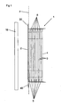
- Figs. 1-3 disclose a side view of a plate heat exchanger comprising a plate package 1 with a frame plate 2, a plurality of heat exchanger plates 3 and a pressure plate 4.
- the plates 2, 3. 4 extend substantially in parallel to a main extension plane p.
- the frame plate 2 and the pressure plate 4 are provided on a respective side of the heat exchanger plates 3.
- the frame plate 2, all heat exchanger plates 3 and the pressure plate 4 are permanently joined to each other, for instance by means of brazing, gluing, welding or the like.
- the heat exchanger plates 3 in the plate package 1 form a plurality of plate interspaces comprising first plate interspaces 5 for a first medium and second plate interspaces 6 for a second medium.
- the plate interspaces 5, 6 are provided in an alternating order in the plate package 1 in such a way that every second plate interspace is a second plate interspace 6 and the remaining plate interspaces are first plate interspaces 5.
- the plate interspace located most closely to the frame plate 2 is a first plate interspace 5, see Fig. 1 .
- the first plate interspaces 5 are arranged to receive a first medium having a relatively low first working pressure.
- the second plate interspaces 6 are arranged to receive a second medium having a relatively high second working pressure.
- the plate heat exchanger disclosed is suitable for being provided in an apparatus for heating of hot-water.
- the first plate interspaces 5 may receive and convey a first medium, in this case a primary medium for heating of a second medium which then is a secondary medium in the form of tap hot-water, which is received and conveyed through the second plate interspaces 6.
- the working pressure of the primary medium in the first plate interspaces 5 may be 2-4 bars, for instance approximately 3 bars, whereas the working pressure of the secondary medium in the second plate interspaces 6 may be 8-12 bars, for instance approximately 10 bars.
- the plate package 1 has two opposite short sides 1a and 1b, and two opposite long sides 1 c and 1 d, see Fig. 3 .
- the plate package 1 defines a longitudinal centre axis x, which extends centrally along the frame plate 2 in parallel with or substantially in parallel with the two long sides 1 c and 1d.
- the plate package 1 has, seen in a direction towards the frame plate 2, a first side with regard to the centre axis x and a second side 16 with regard to the centre axis x.
- the frame plate 2 and each of the heat exchanger plates 3 have four portholes, which form four ports 11, 12, 13 and 14 that extend through the frame plate 2 and the heat exchanger plates 3.
- the ports 11-14 comprise a first inlet port 11 and a first outlet port 12 for the first medium, and a second inlet port 13 and a second outlet port 14 for the second medium.
- the first inlet port 11 and the first outlet port 12 communicate with the first plate interspaces 5 and are provided on the first side 15 of the centre axis x.
- the second inlet port 13 and the second outlet port 14 communicate with the second plate interspaces 6 and are provided on the second side16 of the centre axis x.
- the two media thus flow in parallel to each other, but in opposite directions, see Figs. 2 and 4 , or in the same direction, see Fig. 6 .
- the ports 11-14 are symmetric with respect to the centre axis x, which means that the ports 11 and 12 on the first side 15 are located at the same absolute distance from the centre axis x as the ports 13 and 14 on the second side 16.
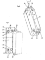
- the plate heat exchanger comprises or co-operates with a connecting member 18 having an abutment surface 19 abutting the frame plate 2 of the plate package 1 in a mounted position when the plate package 1 is ready to be used.
- the connecting member 18 comprises four connecting conduits 21, 22, 23 and 24, which are located opposite to a respective one of the four ports 11-14 in the mounted position.
- Each connecting conduit 21-24 has an orifice in the abutment surface 19.
- Each such orifice is surrounded by a gasket 25, sealing the transition between the respective ports 11-14 and 21-24 in the mounted position.
- the connecting member 18 may belong to the plate heat exchanger or the apparatus on which the plate package 1 is to be provided.
- the plate package 1 comprises one or several first attachment members 30 which are located at a first of the short sides 1 a, and one or several second attachment members 40 which are located at the second short side 1b.
- the attachment members 30, 40 are in the embodiments disclosed, comprised by the frame plate 2, but may for instance also be provided on any other plate, for instance on a strengthening plate provided outside the frame plate 2.
- the attachment members 30, 40 are positioned in relation to the centre axis x and the ports 11-14 in such a manner that forces caused by the difference between the first working pressure and the second working pressure are balanced.
- the attachment members 30, 40 are designed as attachment tabs extending outwardly from the frame plate 2. Such attachment tabs may advantageously constitute an integrated part of the frame plate 2, or more precisely of the sheet forming the frame plate 2.
- the attachment members 30, 40 may of course have another shape than the one disclosed, and for instance comprise a wider sheet than the tabs disclosed.
- the attachment members 30, 40 are arranged to be in engagement with corresponding attachments 46 of the connecting member 18 in the mounted position.
- each attachment member 30, 40 comprises a hole 45 for receiving a screw (not disclosed) which is intended to extend through the hole 45 and into a preferably threaded hole forming the above-mentioned attachment 46 of the connecting member 18.
- the holes 45 of the attachment members 30, 40 are thus located opposite to the corresponding holes of the attachments 46 of the connecting member 18.
- the attachment members 30, 40 for instance may be formed by a respective sheet extending along the whole respective short side 1 a, 1b with holes provided in corresponding positions as in the embodiments disclosed.
- one or several of the attachment members 30, 40 may lack holes and be intended to be inserted, for instance, into corresponding pockets, grooves, recesses or the like in the connecting member 18.
- the attachment members comprise or consist of one single first attachment member 30 at the first short side 1 a, and one single second attachment member 40 at the second short side 1b. Both the attachment members 30, 40 are then positioned on the second side 16 of the centre axis x, i.e. the side comprising the port 13 and 14 for the second medium with the higher working pressure.
- the moment around the attachment members 30, 40 should more specifically be as small as possible in order to reduce the risk of leakage, which means that the two attachment members 30, 40 are to be positioned at the same distance from the centre line x, for instance between the centre line x and the centre points of the ports 13, 14, and in an extreme case the attachment members 30, 40 are positioned to be aligned with the centre points of the ports 13, 14.
- the attachment members comprise or consist of one single first attachment member 30 at the first short side 1a and two second attachment members 40 at the second short side 1b.
- the first attachment member 30 and one of the second attachment members 40 are then positioned on the second side 16 of the centre axis x, i.e. the side comprising the ports 13 and 14 for the second medium with the higher working pressure.
- the attachment members 30, 40 should be displaced towards the second side 16, wherein the two attachment members located on the second side 16 should be located between the centre line x and the centre points of the ports 13, 14.
- all angles of the triangle formed by the attachment members 30, 40 are smaller than or equal to 90°.
- the attachment members comprise or consist of two first attachment members 30 and two second attachment members 40.
- One of the first attachment members 30 and one of the second attachment members 40 are then positioned on the second side 16 of the centre axis x.
- the attachment members 30, 40 are positioned in such a manner that the attachment members 30, 40 on the second side 16 of the centre axis x are located at a greater distance from the centre axis x than the attachment members 30, 40 on the first side 15 of the centre axis x.
- one of the attachment members 30, 40 is located along each short side 1 a, 1b on a respective side of the centre axis x.
- All attachment members 30, 40 are suitably located at an absolute distance from the centre line x which is less or equal to the distance from the centre line to the ports 11, 12 and 13, 14, respectively.
- all, i.e. one or several, of the first attachment members 30 and all, i.e. one or several, of the second attachment members 40 have a common geometric centre of gravity 50, which is located on the second side 16 of the centre axis x, i.e. on the side comprising the ports 13 and 14 for the second medium with the higher working pressure. In such a manner, the above-mentioned balancing of the pressure difference between the working pressures is achieved. All attachment members 30, 40 thus form a geometric figure, which in the examples disclosed is a straight line, see Fig.
- the centre of gravity 50 is also the centre of the geometric figure, i.e. the absolute distance from the centre to each of the attachment members 30, 40 is equal.
- the plate package 1 of course may comprise several attachment members 30, 40 and/or attachment members 30, 40 which form other geometric figures than the ones disclosed herein.
- the position of the attachment members 30, 40 is intended in this application the position of the attachment members 30, 40 in the extension plane p. More precisely, it is referred to a position for a point of each attachment members 30, 40 in which the attachment forces of the attachment member are concentrated.
- the position of the attachment members 30, 40 in depth, i.e. perpendicular to the extension plane p, may vary, wherein the attachments 46 of the connecting member are positioned in correspondence with such a position of the attachment members 30, 40.
- the attachment members 30, 40 may have a plane extension as in the embodiments described above, but also a curved or angled extension for engagement with the attachments 46.
- the attachment members 30, 40 may then be connected to the plate package 1 at a distance from the frame plate 2.
- the ports are as mentioned above symmetric with respect to the centre axis x.
- the attachment members 30, 40 should also then be positioned in relation to the centre axis x and the ports 11-14 in such a manner that the above-mentioned asymmetric forces are balanced.
Landscapes
- Engineering & Computer Science (AREA)
- Physics & Mathematics (AREA)
- Thermal Sciences (AREA)
- Mechanical Engineering (AREA)
- General Engineering & Computer Science (AREA)
- Heat-Exchange Devices With Radiators And Conduit Assemblies (AREA)
- Separation By Low-Temperature Treatments (AREA)
Priority Applications (1)
| Application Number | Priority Date | Filing Date | Title |
|---|---|---|---|
| PL07820275T PL2064507T3 (pl) | 2006-09-22 | 2007-09-18 | Płytowy wymiennik ciepła |
Applications Claiming Priority (2)
| Application Number | Priority Date | Filing Date | Title |
|---|---|---|---|
| SE0601973A SE531819C2 (sv) | 2006-09-22 | 2006-09-22 | Plattvärmeväxlare |
| PCT/EP2007/059809 WO2008034812A1 (en) | 2006-09-22 | 2007-09-18 | A plate heat exchanger |
Publications (2)
| Publication Number | Publication Date |
|---|---|
| EP2064507A1 EP2064507A1 (en) | 2009-06-03 |
| EP2064507B1 true EP2064507B1 (en) | 2011-11-16 |
Family
ID=38922458
Family Applications (1)
| Application Number | Title | Priority Date | Filing Date |
|---|---|---|---|
| EP07820275A Active EP2064507B1 (en) | 2006-09-22 | 2007-09-18 | A plate heat exchanger |
Country Status (6)
| Country | Link |
|---|---|
| EP (1) | EP2064507B1 (sv) |
| AT (1) | ATE534008T1 (sv) |
| ES (1) | ES2374322T3 (sv) |
| PL (1) | PL2064507T3 (sv) |
| SE (1) | SE531819C2 (sv) |
| WO (1) | WO2008034812A1 (sv) |
Families Citing this family (2)
| Publication number | Priority date | Publication date | Assignee | Title |
|---|---|---|---|---|
| SE532084C2 (sv) * | 2007-05-10 | 2009-10-20 | Alfa Laval Corp Ab | Plattvärmeväxlare |
| WO2017220489A1 (en) | 2016-06-20 | 2017-12-28 | Swep International Ab | Heat exchanger |
Family Cites Families (3)
| Publication number | Priority date | Publication date | Assignee | Title |
|---|---|---|---|---|
| DE19737247A1 (de) * | 1997-08-27 | 1999-03-04 | Knecht Filterwerke Gmbh | Wärmetauscher mit einer Mehrzahl übereinander gestapelter Wärmetauscherplatten |
| DE10304733A1 (de) * | 2003-02-06 | 2004-08-19 | Modine Manufacturing Co., Racine | Plattenwärmetauscher |
| DE10347181B4 (de) * | 2003-10-10 | 2005-12-22 | Modine Manufacturing Co., Racine | Wärmetauscher, insbesondere Ölkühler |
-
2006
- 2006-09-22 SE SE0601973A patent/SE531819C2/sv unknown
-
2007
- 2007-09-18 ES ES07820275T patent/ES2374322T3/es active Active
- 2007-09-18 PL PL07820275T patent/PL2064507T3/pl unknown
- 2007-09-18 WO PCT/EP2007/059809 patent/WO2008034812A1/en active Application Filing
- 2007-09-18 EP EP07820275A patent/EP2064507B1/en active Active
- 2007-09-18 AT AT07820275T patent/ATE534008T1/de active
Also Published As
| Publication number | Publication date |
|---|---|
| SE531819C2 (sv) | 2009-08-18 |
| ATE534008T1 (de) | 2011-12-15 |
| PL2064507T3 (pl) | 2012-04-30 |
| SE0601973L (sv) | 2008-03-23 |
| ES2374322T3 (es) | 2012-02-15 |
| EP2064507A1 (en) | 2009-06-03 |
| WO2008034812A1 (en) | 2008-03-27 |
Similar Documents
| Publication | Publication Date | Title |
|---|---|---|
| EP2594885B1 (en) | Heat exchanger having extended heat transfer surface around fastening points | |
| EP2002195B1 (en) | Plate heat exchanger including strengthening plates provided outside of the outermost heat exhanger plates | |
| EP2394129B1 (en) | A plate heat exchanger | |
| CN111316057B (zh) | 多流体热交换器 | |
| AU2010356148A1 (en) | A heat exchanger plate and a plate heat exchanger | |
| CN107614999B (zh) | 热交换器和热交换器箱体 | |
| EP2064507B1 (en) | A plate heat exchanger | |
| CA2861234C (en) | Plate heat exchanger with improved strength in port area | |
| US20190137197A1 (en) | Printed circuit-type heat exchanger having integral structure | |
| US11150027B2 (en) | Heat exchanger and method of making a heat exchanger | |
| US11460256B2 (en) | Heat exchanger header | |
| EP3473961B1 (en) | Heat exchanger | |
| EP3418667A1 (en) | Heat exchanger and header for the same | |
| CN113227545B (zh) | 用于冷却多个流体的热交换器 | |
| CN112902712A (zh) | 一种芯片冷却换热器 | |
| US20140196869A1 (en) | Plate heat exchanger with tension ties | |
| GB2607094A (en) | Heat exchanger | |
| WO2024061823A1 (en) | A plate heat exchanger |
Legal Events
| Date | Code | Title | Description |
|---|---|---|---|
| PUAI | Public reference made under article 153(3) epc to a published international application that has entered the european phase |
Free format text: ORIGINAL CODE: 0009012 |
|
| 17P | Request for examination filed |
Effective date: 20090112 |
|
| AK | Designated contracting states |
Kind code of ref document: A1 Designated state(s): AT BE BG CH CY CZ DE DK EE ES FI FR GB GR HU IE IS IT LI LT LU LV MC MT NL PL PT RO SE SI SK TR |
|
| AX | Request for extension of the european patent |
Extension state: AL BA HR MK RS |
|
| GRAP | Despatch of communication of intention to grant a patent |
Free format text: ORIGINAL CODE: EPIDOSNIGR1 |
|
| RIN1 | Information on inventor provided before grant (corrected) |
Inventor name: BJOERNSSON, PETER Inventor name: GUDMUNDSSON, THORD |
|
| GRAS | Grant fee paid |
Free format text: ORIGINAL CODE: EPIDOSNIGR3 |
|
| GRAA | (expected) grant |
Free format text: ORIGINAL CODE: 0009210 |
|
| DAX | Request for extension of the european patent (deleted) | ||
| AK | Designated contracting states |
Kind code of ref document: B1 Designated state(s): AT BE BG CH CY CZ DE DK EE ES FI FR GB GR HU IE IS IT LI LT LU LV MC MT NL PL PT RO SE SI SK TR |
|
| REG | Reference to a national code |
Ref country code: GB Ref legal event code: FG4D |
|
| REG | Reference to a national code |
Ref country code: CH Ref legal event code: NV Representative=s name: ISLER & PEDRAZZINI AG Ref country code: CH Ref legal event code: EP |
|
| REG | Reference to a national code |
Ref country code: IE Ref legal event code: FG4D |
|
| REG | Reference to a national code |
Ref country code: DE Ref legal event code: R096 Ref document number: 602007018809 Country of ref document: DE Effective date: 20120112 |
|
| REG | Reference to a national code |
Ref country code: ES Ref legal event code: FG2A Ref document number: 2374322 Country of ref document: ES Kind code of ref document: T3 Effective date: 20120215 |
|
| REG | Reference to a national code |
Ref country code: NL Ref legal event code: T3 |
|
| LTIE | Lt: invalidation of european patent or patent extension |
Effective date: 20111116 |
|
| PG25 | Lapsed in a contracting state [announced via postgrant information from national office to epo] |
Ref country code: LT Free format text: LAPSE BECAUSE OF FAILURE TO SUBMIT A TRANSLATION OF THE DESCRIPTION OR TO PAY THE FEE WITHIN THE PRESCRIBED TIME-LIMIT Effective date: 20111116 Ref country code: IS Free format text: LAPSE BECAUSE OF FAILURE TO SUBMIT A TRANSLATION OF THE DESCRIPTION OR TO PAY THE FEE WITHIN THE PRESCRIBED TIME-LIMIT Effective date: 20120316 |
|
| REG | Reference to a national code |
Ref country code: PL Ref legal event code: T3 |
|
| REG | Reference to a national code |
Ref country code: SK Ref legal event code: T3 Ref document number: E 11190 Country of ref document: SK |
|
| PG25 | Lapsed in a contracting state [announced via postgrant information from national office to epo] |
Ref country code: BE Free format text: LAPSE BECAUSE OF FAILURE TO SUBMIT A TRANSLATION OF THE DESCRIPTION OR TO PAY THE FEE WITHIN THE PRESCRIBED TIME-LIMIT Effective date: 20111116 Ref country code: PT Free format text: LAPSE BECAUSE OF FAILURE TO SUBMIT A TRANSLATION OF THE DESCRIPTION OR TO PAY THE FEE WITHIN THE PRESCRIBED TIME-LIMIT Effective date: 20120316 Ref country code: GR Free format text: LAPSE BECAUSE OF FAILURE TO SUBMIT A TRANSLATION OF THE DESCRIPTION OR TO PAY THE FEE WITHIN THE PRESCRIBED TIME-LIMIT Effective date: 20120217 Ref country code: SI Free format text: LAPSE BECAUSE OF FAILURE TO SUBMIT A TRANSLATION OF THE DESCRIPTION OR TO PAY THE FEE WITHIN THE PRESCRIBED TIME-LIMIT Effective date: 20111116 Ref country code: LV Free format text: LAPSE BECAUSE OF FAILURE TO SUBMIT A TRANSLATION OF THE DESCRIPTION OR TO PAY THE FEE WITHIN THE PRESCRIBED TIME-LIMIT Effective date: 20111116 Ref country code: SE Free format text: LAPSE BECAUSE OF FAILURE TO SUBMIT A TRANSLATION OF THE DESCRIPTION OR TO PAY THE FEE WITHIN THE PRESCRIBED TIME-LIMIT Effective date: 20111116 |
|
| PG25 | Lapsed in a contracting state [announced via postgrant information from national office to epo] |
Ref country code: CY Free format text: LAPSE BECAUSE OF FAILURE TO SUBMIT A TRANSLATION OF THE DESCRIPTION OR TO PAY THE FEE WITHIN THE PRESCRIBED TIME-LIMIT Effective date: 20111116 |
|
| PG25 | Lapsed in a contracting state [announced via postgrant information from national office to epo] |
Ref country code: DK Free format text: LAPSE BECAUSE OF FAILURE TO SUBMIT A TRANSLATION OF THE DESCRIPTION OR TO PAY THE FEE WITHIN THE PRESCRIBED TIME-LIMIT Effective date: 20111116 Ref country code: BG Free format text: LAPSE BECAUSE OF FAILURE TO SUBMIT A TRANSLATION OF THE DESCRIPTION OR TO PAY THE FEE WITHIN THE PRESCRIBED TIME-LIMIT Effective date: 20120216 Ref country code: CZ Free format text: LAPSE BECAUSE OF FAILURE TO SUBMIT A TRANSLATION OF THE DESCRIPTION OR TO PAY THE FEE WITHIN THE PRESCRIBED TIME-LIMIT Effective date: 20111116 Ref country code: EE Free format text: LAPSE BECAUSE OF FAILURE TO SUBMIT A TRANSLATION OF THE DESCRIPTION OR TO PAY THE FEE WITHIN THE PRESCRIBED TIME-LIMIT Effective date: 20111116 |
|
| PLBI | Opposition filed |
Free format text: ORIGINAL CODE: 0009260 |
|
| PG25 | Lapsed in a contracting state [announced via postgrant information from national office to epo] |
Ref country code: RO Free format text: LAPSE BECAUSE OF FAILURE TO SUBMIT A TRANSLATION OF THE DESCRIPTION OR TO PAY THE FEE WITHIN THE PRESCRIBED TIME-LIMIT Effective date: 20111116 |
|
| PLAX | Notice of opposition and request to file observation + time limit sent |
Free format text: ORIGINAL CODE: EPIDOSNOBS2 |
|
| 26 | Opposition filed |
Opponent name: SWEP INTERNATIONAL AB Effective date: 20120816 |
|
| REG | Reference to a national code |
Ref country code: DE Ref legal event code: R026 Ref document number: 602007018809 Country of ref document: DE Effective date: 20120816 |
|
| PLAF | Information modified related to communication of a notice of opposition and request to file observations + time limit |
Free format text: ORIGINAL CODE: EPIDOSCOBS2 |
|
| PLBB | Reply of patent proprietor to notice(s) of opposition received |
Free format text: ORIGINAL CODE: EPIDOSNOBS3 |
|
| PG25 | Lapsed in a contracting state [announced via postgrant information from national office to epo] |
Ref country code: MC Free format text: LAPSE BECAUSE OF NON-PAYMENT OF DUE FEES Effective date: 20120930 |
|
| REG | Reference to a national code |
Ref country code: IE Ref legal event code: MM4A |
|
| PG25 | Lapsed in a contracting state [announced via postgrant information from national office to epo] |
Ref country code: FI Free format text: LAPSE BECAUSE OF FAILURE TO SUBMIT A TRANSLATION OF THE DESCRIPTION OR TO PAY THE FEE WITHIN THE PRESCRIBED TIME-LIMIT Effective date: 20111116 |
|
| PG25 | Lapsed in a contracting state [announced via postgrant information from national office to epo] |
Ref country code: IE Free format text: LAPSE BECAUSE OF NON-PAYMENT OF DUE FEES Effective date: 20120918 |
|
| PG25 | Lapsed in a contracting state [announced via postgrant information from national office to epo] |
Ref country code: MT Free format text: LAPSE BECAUSE OF FAILURE TO SUBMIT A TRANSLATION OF THE DESCRIPTION OR TO PAY THE FEE WITHIN THE PRESCRIBED TIME-LIMIT Effective date: 20111116 |
|
| PG25 | Lapsed in a contracting state [announced via postgrant information from national office to epo] |
Ref country code: LU Free format text: LAPSE BECAUSE OF NON-PAYMENT OF DUE FEES Effective date: 20120918 |
|
| PG25 | Lapsed in a contracting state [announced via postgrant information from national office to epo] |
Ref country code: HU Free format text: LAPSE BECAUSE OF FAILURE TO SUBMIT A TRANSLATION OF THE DESCRIPTION OR TO PAY THE FEE WITHIN THE PRESCRIBED TIME-LIMIT Effective date: 20070918 |
|
| PLAY | Examination report in opposition despatched + time limit |
Free format text: ORIGINAL CODE: EPIDOSNORE2 |
|
| REG | Reference to a national code |
Ref country code: FR Ref legal event code: PLFP Year of fee payment: 9 |
|
| PLBC | Reply to examination report in opposition received |
Free format text: ORIGINAL CODE: EPIDOSNORE3 |
|
| REG | Reference to a national code |
Ref country code: FR Ref legal event code: PLFP Year of fee payment: 10 |
|
| REG | Reference to a national code |
Ref country code: FR Ref legal event code: PLFP Year of fee payment: 11 |
|
| REG | Reference to a national code |
Ref country code: FR Ref legal event code: PLFP Year of fee payment: 12 |
|
| PLCK | Communication despatched that opposition was rejected |
Free format text: ORIGINAL CODE: EPIDOSNREJ1 |
|
| STAA | Information on the status of an ep patent application or granted ep patent |
Free format text: STATUS: THE PATENT HAS BEEN GRANTED |
|
| APAH | Appeal reference modified |
Free format text: ORIGINAL CODE: EPIDOSCREFNO |
|
| APBM | Appeal reference recorded |
Free format text: ORIGINAL CODE: EPIDOSNREFNO |
|
| APBP | Date of receipt of notice of appeal recorded |
Free format text: ORIGINAL CODE: EPIDOSNNOA2O |
|
| REG | Reference to a national code |
Ref country code: DE Ref legal event code: R100 Ref document number: 602007018809 Country of ref document: DE |
|
| APBU | Appeal procedure closed |
Free format text: ORIGINAL CODE: EPIDOSNNOA9O |
|
| PLBN | Opposition rejected |
Free format text: ORIGINAL CODE: 0009273 |
|
| STAA | Information on the status of an ep patent application or granted ep patent |
Free format text: STATUS: OPPOSITION REJECTED |
|
| 27O | Opposition rejected |
Effective date: 20190620 |
|
| REG | Reference to a national code |
Ref country code: DE Ref legal event code: R082 Ref document number: 602007018809 Country of ref document: DE Representative=s name: MEISSNER BOLTE PATENTANWAELTE RECHTSANWAELTE P, DE |
|
| P01 | Opt-out of the competence of the unified patent court (upc) registered |
Effective date: 20230414 |
|
| PGFP | Annual fee paid to national office [announced via postgrant information from national office to epo] |
Ref country code: PL Payment date: 20230628 Year of fee payment: 17 |
|
| PGFP | Annual fee paid to national office [announced via postgrant information from national office to epo] |
Ref country code: NL Payment date: 20230816 Year of fee payment: 17 |
|
| PGFP | Annual fee paid to national office [announced via postgrant information from national office to epo] |
Ref country code: TR Payment date: 20230915 Year of fee payment: 17 Ref country code: IT Payment date: 20230810 Year of fee payment: 17 Ref country code: GB Payment date: 20230727 Year of fee payment: 17 Ref country code: AT Payment date: 20230825 Year of fee payment: 17 |
|
| PGFP | Annual fee paid to national office [announced via postgrant information from national office to epo] |
Ref country code: SK Payment date: 20230814 Year of fee payment: 17 Ref country code: FR Payment date: 20230710 Year of fee payment: 17 Ref country code: DE Payment date: 20230726 Year of fee payment: 17 |
|
| PGFP | Annual fee paid to national office [announced via postgrant information from national office to epo] |
Ref country code: ES Payment date: 20231004 Year of fee payment: 17 |
|
| PGFP | Annual fee paid to national office [announced via postgrant information from national office to epo] |
Ref country code: CH Payment date: 20231001 Year of fee payment: 17 |