EP3418667A1 - Heat exchanger and header for the same - Google Patents
Heat exchanger and header for the same Download PDFInfo
- Publication number
- EP3418667A1 EP3418667A1 EP18000540.7A EP18000540A EP3418667A1 EP 3418667 A1 EP3418667 A1 EP 3418667A1 EP 18000540 A EP18000540 A EP 18000540A EP 3418667 A1 EP3418667 A1 EP 3418667A1
- Authority
- EP
- European Patent Office
- Prior art keywords
- header
- fluid manifold
- heat exchanger
- extending
- fluid
- Prior art date
- Legal status (The legal status is an assumption and is not a legal conclusion. Google has not performed a legal analysis and makes no representation as to the accuracy of the status listed.)
- Withdrawn
Links
Images


Classifications
-
- F—MECHANICAL ENGINEERING; LIGHTING; HEATING; WEAPONS; BLASTING
- F28—HEAT EXCHANGE IN GENERAL
- F28F—DETAILS OF HEAT-EXCHANGE AND HEAT-TRANSFER APPARATUS, OF GENERAL APPLICATION
- F28F9/00—Casings; Header boxes; Auxiliary supports for elements; Auxiliary members within casings
- F28F9/02—Header boxes; End plates
- F28F9/0246—Arrangements for connecting header boxes with flow lines
- F28F9/0248—Arrangements for sealing connectors to header boxes
-
- F—MECHANICAL ENGINEERING; LIGHTING; HEATING; WEAPONS; BLASTING
- F02—COMBUSTION ENGINES; HOT-GAS OR COMBUSTION-PRODUCT ENGINE PLANTS
- F02B—INTERNAL-COMBUSTION PISTON ENGINES; COMBUSTION ENGINES IN GENERAL
- F02B29/00—Engines characterised by provision for charging or scavenging not provided for in groups F02B25/00, F02B27/00 or F02B33/00 - F02B39/00; Details thereof
- F02B29/04—Cooling of air intake supply
- F02B29/045—Constructional details of the heat exchangers, e.g. pipes, plates, ribs, insulation, materials, or manufacturing and assembly
- F02B29/0462—Liquid cooled heat exchangers
-
- F—MECHANICAL ENGINEERING; LIGHTING; HEATING; WEAPONS; BLASTING
- F28—HEAT EXCHANGE IN GENERAL
- F28D—HEAT-EXCHANGE APPARATUS, NOT PROVIDED FOR IN ANOTHER SUBCLASS, IN WHICH THE HEAT-EXCHANGE MEDIA DO NOT COME INTO DIRECT CONTACT
- F28D1/00—Heat-exchange apparatus having stationary conduit assemblies for one heat-exchange medium only, the media being in contact with different sides of the conduit wall, in which the other heat-exchange medium is a large body of fluid, e.g. domestic or motor car radiators
- F28D1/02—Heat-exchange apparatus having stationary conduit assemblies for one heat-exchange medium only, the media being in contact with different sides of the conduit wall, in which the other heat-exchange medium is a large body of fluid, e.g. domestic or motor car radiators with heat-exchange conduits immersed in the body of fluid
- F28D1/04—Heat-exchange apparatus having stationary conduit assemblies for one heat-exchange medium only, the media being in contact with different sides of the conduit wall, in which the other heat-exchange medium is a large body of fluid, e.g. domestic or motor car radiators with heat-exchange conduits immersed in the body of fluid with tubular conduits
- F28D1/0408—Multi-circuit heat exchangers, e.g. integrating different heat exchange sections in the same unit or heat exchangers for more than two fluids
- F28D1/0426—Multi-circuit heat exchangers, e.g. integrating different heat exchange sections in the same unit or heat exchangers for more than two fluids with units having particular arrangement relative to the large body of fluid, e.g. with interleaved units or with adjacent heat exchange units in common air flow or with units extending at an angle to each other or with units arranged around a central element
- F28D1/0435—Combination of units extending one behind the other
-
- F—MECHANICAL ENGINEERING; LIGHTING; HEATING; WEAPONS; BLASTING
- F28—HEAT EXCHANGE IN GENERAL
- F28D—HEAT-EXCHANGE APPARATUS, NOT PROVIDED FOR IN ANOTHER SUBCLASS, IN WHICH THE HEAT-EXCHANGE MEDIA DO NOT COME INTO DIRECT CONTACT
- F28D1/00—Heat-exchange apparatus having stationary conduit assemblies for one heat-exchange medium only, the media being in contact with different sides of the conduit wall, in which the other heat-exchange medium is a large body of fluid, e.g. domestic or motor car radiators
- F28D1/02—Heat-exchange apparatus having stationary conduit assemblies for one heat-exchange medium only, the media being in contact with different sides of the conduit wall, in which the other heat-exchange medium is a large body of fluid, e.g. domestic or motor car radiators with heat-exchange conduits immersed in the body of fluid
- F28D1/04—Heat-exchange apparatus having stationary conduit assemblies for one heat-exchange medium only, the media being in contact with different sides of the conduit wall, in which the other heat-exchange medium is a large body of fluid, e.g. domestic or motor car radiators with heat-exchange conduits immersed in the body of fluid with tubular conduits
- F28D1/053—Heat-exchange apparatus having stationary conduit assemblies for one heat-exchange medium only, the media being in contact with different sides of the conduit wall, in which the other heat-exchange medium is a large body of fluid, e.g. domestic or motor car radiators with heat-exchange conduits immersed in the body of fluid with tubular conduits the conduits being straight
- F28D1/0535—Heat-exchange apparatus having stationary conduit assemblies for one heat-exchange medium only, the media being in contact with different sides of the conduit wall, in which the other heat-exchange medium is a large body of fluid, e.g. domestic or motor car radiators with heat-exchange conduits immersed in the body of fluid with tubular conduits the conduits being straight the conduits having a non-circular cross-section
- F28D1/05366—Assemblies of conduits connected to common headers, e.g. core type radiators
- F28D1/05391—Assemblies of conduits connected to common headers, e.g. core type radiators with multiple rows of conduits or with multi-channel conduits combined with a particular flow pattern, e.g. multi-row multi-stage radiators
-
- F—MECHANICAL ENGINEERING; LIGHTING; HEATING; WEAPONS; BLASTING
- F28—HEAT EXCHANGE IN GENERAL
- F28F—DETAILS OF HEAT-EXCHANGE AND HEAT-TRANSFER APPARATUS, OF GENERAL APPLICATION
- F28F9/00—Casings; Header boxes; Auxiliary supports for elements; Auxiliary members within casings
- F28F9/001—Casings in the form of plate-like arrangements; Frames enclosing a heat exchange core
- F28F9/002—Casings in the form of plate-like arrangements; Frames enclosing a heat exchange core with fastening means for other structures
-
- F—MECHANICAL ENGINEERING; LIGHTING; HEATING; WEAPONS; BLASTING
- F28—HEAT EXCHANGE IN GENERAL
- F28F—DETAILS OF HEAT-EXCHANGE AND HEAT-TRANSFER APPARATUS, OF GENERAL APPLICATION
- F28F9/00—Casings; Header boxes; Auxiliary supports for elements; Auxiliary members within casings
- F28F9/02—Header boxes; End plates
- F28F9/0202—Header boxes having their inner space divided by partitions
- F28F9/0204—Header boxes having their inner space divided by partitions for elongated header box, e.g. with transversal and longitudinal partitions
- F28F9/0214—Header boxes having their inner space divided by partitions for elongated header box, e.g. with transversal and longitudinal partitions having only longitudinal partitions
-
- F—MECHANICAL ENGINEERING; LIGHTING; HEATING; WEAPONS; BLASTING
- F28—HEAT EXCHANGE IN GENERAL
- F28F—DETAILS OF HEAT-EXCHANGE AND HEAT-TRANSFER APPARATUS, OF GENERAL APPLICATION
- F28F9/00—Casings; Header boxes; Auxiliary supports for elements; Auxiliary members within casings
- F28F9/02—Header boxes; End plates
- F28F9/0243—Header boxes having a circular cross-section
-
- F—MECHANICAL ENGINEERING; LIGHTING; HEATING; WEAPONS; BLASTING
- F28—HEAT EXCHANGE IN GENERAL
- F28D—HEAT-EXCHANGE APPARATUS, NOT PROVIDED FOR IN ANOTHER SUBCLASS, IN WHICH THE HEAT-EXCHANGE MEDIA DO NOT COME INTO DIRECT CONTACT
- F28D21/00—Heat-exchange apparatus not covered by any of the groups F28D1/00 - F28D20/00
- F28D2021/0019—Other heat exchangers for particular applications; Heat exchange systems not otherwise provided for
- F28D2021/008—Other heat exchangers for particular applications; Heat exchange systems not otherwise provided for for vehicles
- F28D2021/0082—Charged air coolers
-
- F—MECHANICAL ENGINEERING; LIGHTING; HEATING; WEAPONS; BLASTING
- F28—HEAT EXCHANGE IN GENERAL
- F28D—HEAT-EXCHANGE APPARATUS, NOT PROVIDED FOR IN ANOTHER SUBCLASS, IN WHICH THE HEAT-EXCHANGE MEDIA DO NOT COME INTO DIRECT CONTACT
- F28D21/00—Heat-exchange apparatus not covered by any of the groups F28D1/00 - F28D20/00
- F28D2021/0019—Other heat exchangers for particular applications; Heat exchange systems not otherwise provided for
- F28D2021/008—Other heat exchangers for particular applications; Heat exchange systems not otherwise provided for for vehicles
- F28D2021/0089—Oil coolers
-
- F—MECHANICAL ENGINEERING; LIGHTING; HEATING; WEAPONS; BLASTING
- F28—HEAT EXCHANGE IN GENERAL
- F28D—HEAT-EXCHANGE APPARATUS, NOT PROVIDED FOR IN ANOTHER SUBCLASS, IN WHICH THE HEAT-EXCHANGE MEDIA DO NOT COME INTO DIRECT CONTACT
- F28D21/00—Heat-exchange apparatus not covered by any of the groups F28D1/00 - F28D20/00
- F28D2021/0019—Other heat exchangers for particular applications; Heat exchange systems not otherwise provided for
- F28D2021/008—Other heat exchangers for particular applications; Heat exchange systems not otherwise provided for for vehicles
- F28D2021/0091—Radiators
- F28D2021/0094—Radiators for recooling the engine coolant
-
- F—MECHANICAL ENGINEERING; LIGHTING; HEATING; WEAPONS; BLASTING
- F28—HEAT EXCHANGE IN GENERAL
- F28F—DETAILS OF HEAT-EXCHANGE AND HEAT-TRANSFER APPARATUS, OF GENERAL APPLICATION
- F28F21/00—Constructions of heat-exchange apparatus characterised by the selection of particular materials
- F28F21/08—Constructions of heat-exchange apparatus characterised by the selection of particular materials of metal
- F28F21/081—Heat exchange elements made from metals or metal alloys
- F28F21/084—Heat exchange elements made from metals or metal alloys from aluminium or aluminium alloys
-
- F—MECHANICAL ENGINEERING; LIGHTING; HEATING; WEAPONS; BLASTING
- F28—HEAT EXCHANGE IN GENERAL
- F28F—DETAILS OF HEAT-EXCHANGE AND HEAT-TRANSFER APPARATUS, OF GENERAL APPLICATION
- F28F2220/00—Closure means, e.g. end caps on header boxes or plugs on conduits
-
- F—MECHANICAL ENGINEERING; LIGHTING; HEATING; WEAPONS; BLASTING
- F28—HEAT EXCHANGE IN GENERAL
- F28F—DETAILS OF HEAT-EXCHANGE AND HEAT-TRANSFER APPARATUS, OF GENERAL APPLICATION
- F28F2255/00—Heat exchanger elements made of materials having special features or resulting from particular manufacturing processes
- F28F2255/16—Heat exchanger elements made of materials having special features or resulting from particular manufacturing processes extruded
-
- F—MECHANICAL ENGINEERING; LIGHTING; HEATING; WEAPONS; BLASTING
- F28—HEAT EXCHANGE IN GENERAL
- F28F—DETAILS OF HEAT-EXCHANGE AND HEAT-TRANSFER APPARATUS, OF GENERAL APPLICATION
- F28F2275/00—Fastening; Joining
- F28F2275/20—Fastening; Joining with threaded elements
- F28F2275/205—Fastening; Joining with threaded elements with of tie-rods
-
- Y—GENERAL TAGGING OF NEW TECHNOLOGICAL DEVELOPMENTS; GENERAL TAGGING OF CROSS-SECTIONAL TECHNOLOGIES SPANNING OVER SEVERAL SECTIONS OF THE IPC; TECHNICAL SUBJECTS COVERED BY FORMER USPC CROSS-REFERENCE ART COLLECTIONS [XRACs] AND DIGESTS
- Y02—TECHNOLOGIES OR APPLICATIONS FOR MITIGATION OR ADAPTATION AGAINST CLIMATE CHANGE
- Y02T—CLIMATE CHANGE MITIGATION TECHNOLOGIES RELATED TO TRANSPORTATION
- Y02T10/00—Road transport of goods or passengers
- Y02T10/10—Internal combustion engine [ICE] based vehicles
- Y02T10/12—Improving ICE efficiencies
Definitions
- Heat exchangers are used to transfer thermal energy from one stream of fluid at a first, higher temperature to another stream of fluid at a second, lower temperature. Oftentimes such heat exchangers are used to remove waste heat from a process fluid such as oil, coolant, or the like by transferring that heat to a flow of cooler air directed to pass through the heat exchanger.
- process fluid such as oil, coolant, or the like
- the process fluid to be cooled is also at an operating pressure that is substantially greater than the ambient atmospheric pressure of the heat exchanger's surroundings.
- the heat exchanger it becomes necessary for the heat exchanger to be designed to withstand the pressure forces that result from the process fluid passing through the heat exchanger. This can become challenging, especially in cases where the heat exchanger is to be used in large systems and machinery such as, for example, construction equipment, agricultural machines, and the like.
- the flow rate of the process fluid also increases, necessitating larger heat exchangers to accommodate both the heat transfer requirements and the fluid flow rates.
- the fluid to be cooled is directed through an array of flat tubes extending between two tanks or headers.
- heat exchangers become larger, they can have substantially large surface areas exposed to the pressure of the process fluid, especially in the tank or header areas, and the force of the fluid pressure acting on these large surfaces can lead to destructive mechanical stresses in the heat exchanger structure.
- the ability to withstand such pressures can be improved through the use of circular header profiles, but circular headers can be difficult to package within a compact space as the required size of the heat exchanger increases.
- a header for a heat exchanger includes a first and a second cylindrical fluid manifold extending in parallel.
- Each of the first and second manifolds have tube slots that extend through an arcuate wall section of the manifold.
- a thickened wall section of the header having a generally triangular wall section is bounded by the first and second fluid manifolds and by a planar outer surface of the header.
- An aperture extends through the thickened wall section to provide a fluid communication pathway between the first and second cylindrical fluid manifolds.
- the header includes a plug that is inserted into an opening that extends through the planar outer surface to the aperture.
- the plug is brazed to the planar outer surface.
- the plug includes an integral mounting pin that extends outwardly from the header in a direction perpendicular to the planar outer surface.
- the arcuate wall section of one of the manifolds defines a minimum wall thickness of the header, and the insertion depth of the plug through the opening is approximately equal to that minimum wall thickness.
- the header includes a third cylindrical fluid manifold adjacent to and parallel to the second fluid manifold.
- a second thickened wall section of the header having a generally triangular wall section is bounded by the third and second fluid manifolds and by the planar outer surface of the header.
- an aperture extends through the second thickened wall section to provide a fluid communication pathway between the second and third fluid manifolds.
- the header includes a first and a second mounting flange extending from the header.
- the first mounting flange defines a first mounting plane and the second mounting flange defines a second mounting plane, with both the first and second mounting planes being oriented parallel to one another and perpendicular to the planar outer surface of the header.
- a first mounting hole extends through the first mounting flange and is aligned with a second mounting hole that extends through the second mounting flange. In some such embodiments all of the fluid manifolds are entirely located between the first and second mounting planes.
- a method of making a header for a heat exchanger includes providing an extruded section with two unconnected cylindrical volumes arranged therein and with a planar outer surface, and machining through the planar outer surface to define an aperture between the two cylindrical volumes. The act of machining through the planar outer surface creates an opening in that surface, and a plug is inserted into the opening. In some embodiments the plug is brazed to the extruded section in order to secure it within the opening. In some embodiments a series of tube slots are formed into arcuate wall sections of the two cylindrical volumes opposite the planar outer surface.
- a heat exchanger includes a first series of parallel-arranged flat tubes to convey a first fluid through the heat exchanger, and a second series of parallel-arranged flat tubes to convey a second fluid through the heat exchanger.
- the first and second fluids are, for example, two fluids used within a power generating system (such as an internal combustion engine system, for example) that are cooled within the heat exchanger by a flow of air passing through the heat exchanger over the outer surfaces of the flat tubes.
- Such fluids can include, but are not limited to, liquid coolants, water, refrigerant, oil, and others.
- the first and second series of flat tubes extend between a first and a second header arranged at opposing ends of the heat exchanger.
- Each of the headers has at least two cylindrical fluid manifolds, each of which is provided with tube slots that extend through an arcuate wall section of the header. Ends of the tubes are received within the tube slots.
- the headers are provided with more than two cylindrical fluid manifolds and the heat exchanger includes a corresponding additional series of parallel-arranged flat tubes.
- the additional series of tubes carries a third fluid that is distinct from the first and the second fluids.
- distinct is meant that there is no hydraulic connection within the heat exchanger between the fluids.
- the fluids could, however, be hydraulically connected elsewhere within the system.
- a third series of flat tubes is hydraulically connected within the heat exchanger to one of the first and second series of flat tubes, so that the corresponding one of the first and second fluids also flows through that third series of flat tubes.
- a heat exchanger 1 according to an embodiment of the invention is depicted in FIG. 1 , and includes a heat exchange core 2 bounded between two side plates 4.
- the heat exchange core 2 is constructed as a stacked and brazed assembly of alternating layers of flat tubes 5 and corrugated fins 6, as shown in the core detail of FIG. 2 .
- the tubes 5 and fins 6 are preferably formed of an aluminum alloy so that the heat exchanger 1 can be built to be lightweight and highly efficient in the transfer of heat between a first fluid flowing through the interiors of the tubes 5 and a second fluid (air, for example) passing through the corrugations of the fins 6.
- Such a heat exchanger 1 can be used as, for example, a vehicular powertrain cooling heat exchanger to cool engine oil, transmission oil, engine coolant, or some other fluid from which dissipation of heat is desired.
- Each header 3 is an assembly of parts, shown in exploded view in FIG. 3 .
- the header 3 includes an extruded section 7 that extends over generally the full stacked height of the heat exchange core 2, and provides a number of cylindrical fluid manifolds 8 that distribute the first fluid to, or receive the first fluid from, the array of tubes 5.
- the number of cylindrical fluid manifolds 8 that is provided by each extruded section 7 corresponds to the number of tubes 5 provided in each row of tubes of the core 2 (e.g. two, in the exemplary embodiment of FIGs. 1-5 ).
- each of the cylindrical fluid manifolds 8 is bounded by an arcuate wall section 9 over a majority of the circular periphery of the manifold, with that arcuate wall section 9 having a generally constant wall thickness (indicated by the reference number 20).
- the arcuate wall sections 9 of the two adjacent manifolds 8 merge together.
- a planar outer surface 14 of the header is provided on the opposing (i.e. the non-core-facing) side of the header 3.
- the planar outer surface 14, together with the cylindrical manifolds 8, bounds a thickened wall section 21 of the extruded section 7.
- the thickened wall section 21 has a generally triangular cross-section, as indicated in FIG. 5 by the dashed triangle 22), with a wall thickness that is substantially greater than the wall thickness 20 of the arcuate wall sections 9. As indicated by FIG. 5 , the cross-section of the thickened wall section 21 can deviate somewhat from a truly triangular shape while still exhibiting a generally triangular cross-section.
- Tube slots 13 are provided along the lengths of the headers 3 to receive the ends of the tubes 5 into the corresponding cylindrical fluid manifolds 8.
- the tube slots 13 can be formed into the extruded section 7 by, for example, saw-cutting or piercing.
- Each of the tube slots 13 extends through one of the arcuate wall sections 9, and has a width and height that generally corresponds to the major and minor dimensions of the flat tubes 5.
- the ends of the flat tubes 5 are preferably inserted into the tube slots 13 after the flat tubes 5 and the fins 6 have been stacked to form the core 2, so that the tubes 5 can be brazed to the headers 3 in the same brazing operation as is used to join the flat tubes 5 to the fins 6, thereby creating leak-free joints at the tube-to-header interfaces.
- the cylindrical fluid manifolds 8 are hydraulically connected by way of one or more apertures 15 that extend through the thickened wall section 21 at one or more locations along the length of the header 3.
- Such an aperture 15 can be formed by a machining operation such as drilling or milling through the planar surface 14 to a predetermined depth, in which case the forming of the aperture 15 can define a circular opening 40 in the planar surface 14, as shown in FIG. 3 .
- the predetermined depth is selected to be less than the depth that would be required in order to remove all of the material separating the cylindrical fluid manifolds 8 at that location. As best seen in the cross-sectional view of FIG.
- the aperture 15 of the exemplary embodiment has the material in the thickened wall section 21 removed to a depth, as measured from the planar surface 14, that is approximately equal to the radius of the arcuate wall sections 9. While the exemplary embodiment depicts a circular opening 40 formed in the planar outer surface 14, it should be understood that other machining methods might result in non-circular openings.
- a plug 12 can be inserted into the opening 40 defined by the forming of the aperture 15 at the planar outer surface 14 in order to provide a fluid-tight seal between the fluid manifolds 8 and the outside environment external to the header 3.
- the plug 12 includes an insertion portion 18 with a profile that generally matches the opening 40 created in the planar surface 14, so that the plug 12 can be partially inserted into that opening 40 with minimal clearance between side surfaces of the insertion portion 18 and the opening 40.
- a peripheral flange portion 17 extends beyond the outer periphery of the insertion portion 18 by an amount sufficient to engage and bear upon the planar surface 14 surrounding the opening 40, thereby limiting the insertion depth of the plug 12.
- the height of the insertion portion 18 (and, therefore, the depth of insertion of the plug 12 into the opening 40) is approximately equal to the wall thickness 20 of the arcuate wall sections 9.
- a groove 25 can be provided in the face of the peripheral flange portion 17 that is disposed against the planar surface 14, and can be used to accommodate a ring of braze material 16.
- the plug 12, along with the ring of braze material 16, can be assembled to the extruded section 7 prior to brazing of the heat exchanger 1, so that the plug 12 can be secured into the header 3 during the brazing operation.
- One or more of the plugs 12 can be provided with an integral mounting pin 19 extending outwardly away from the header in a direction perpendicular to the planar outer surface 14.
- the integral mounting pins 19 can be accommodated into corresponding holes of other components to which the heat exchanger 1 is to be assembled in order to, for example, secure the heat exchanger 1 within a cooling module.
- Annular vibration isolators can be conveniently assembled over the mounting pin 19 and bear against the peripheral flange portion 17 of the plug 12.
- each of the headers 3 is provided with three end caps 11 and one fluid port 10, so that the fluid to be cooled within the heat exchanger 1 can be received into one of the headers 3 (the inlet header) through its fluid port 10 and can be removed from the other one of the headers 3 (the outlet header) through its fluid port 10.
- the apertures 15 provided in that header 3 allow at least some of the fluid to pass into the adjacent cylindrical fluid manifold 8 so that the flat tubes 5 connected to each of those fluid manifolds 8 are placed hydraulically in parallel with one another.
- the fluid received into that one of the cylindrical fluid manifolds 8 of the outlet header 3 can be transferred by way of the apertures 15 into the cylindrical fluid manifold 8 having the outlet port 10.
- the present invention is able to provide a more robust design for applications wherein the fluid to be cooled is at an elevated pressure.
- the ability of the fluid manifold to withstand the elevated internal pressures imposed by the fluid is increased by reducing the diameter of each fluid manifold, without sacrificing the total flow area provided by the flat tubes 5.
- the number of cylindrical fluid manifolds 8 that may be provided in each of the headers 3 is not limited to two. Additional fluid manifolds 8 can be provided, and can be fluidly connected to adjacent fluid manifolds through additional apertures 15. It should be understood that a multipass heat exchanger can also be provided by placing apertures 15 between some, but not all, of the adjacent fluid manifolds 8.
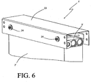
- FIGs. 6-7 a portion of a heat exchanger 1' is depicted in FIGs. 6-7 .
- the heat exchanger 1' includes a heat exchange core 2' that is substantially similar to the heat exchange core 2 depicted in FIG. 2 , except that three rows of flat tubes 5 are provided in each layer of tubes.
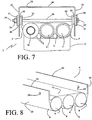
- a header 3' provided at either end of the core 2' includes an extruded section 7' that includes three cylindrical fluid manifolds 8 arranged side-by-side to receive the ends of the tubes 5 in similar fashion as was described previously with reference to the embodiment of FIG. 1 .
- the extruded section 7' shown in greater detail in FIG. 8 , is similar to the previously described extruded section 7 in that it includes an arcuate wall section 9 over a majority of the circular periphery of each manifold 8, with the arcuate wall sections 9 having a generally constant wall thickness.
- the ends of the tubes 5 are received into the fluid manifold through slots provided in those arcuate wall sections 9.
- a planar outer surface 14 is again provided on the opposing (i.e. the non-core-facing) side of the header 3'.
- the extruded header section 7' can optionally be provided with mounting flanges 33, as shown in FIGs. 6-8 .
- the mounting flanges 33 extend in a direction that is perpendicular to the planar surface 14 and is directed away from the heat exchange core 2, thereby defining a pair of mounting planes 35 (i.e. a first mounting plane 35 and a second mounting plane 35) for the heat exchanger 1' which are likewise arranged perpendicular to the planar surface 14.
- the cylindrical fluid manifolds 8 provided by the header 3' are all located entirely between the pair of mounting planes 35. While the mounting flanges 33 are depicted as extending from the arcuate wall sections 9, it should be understood that they can alternatively or in addition extend from the planar surface 14.
- the mounting flanges 33 can be used to structurally mount the heat exchanger 1' into a cooling module or other assembly, as shown in FIGs. 6-7 .
- a U-channel 23 that forms part of the cooling module or other assembly includes parallel, spaced-apart legs 27 joined by a connecting section 26, with the space between the legs 27 sized to be sufficiently large to allow for the header 3' to be received there between.
- Connection assemblies 24 structurally connect the header 3' to the U-channel 23, and include compressible rubber isolators 32 that are inserted into holes placed within the U-channel 23 so that a portion of each isolator 32 is arranged inside of the U-channel 23 and another portion of the isolator 32 is arranged outside of the U-channel 23.
- the isolators 32 are provided in pairs at locations that align with corresponding mounting holes 34 provided in the flanges 33, so that a bolt 28 or other similar fastener can be inserted through the paired isolators 32 and the corresponding mounting holes 34 in the flanges 33.
- Washers 31 are provided between a head 29 of the bolt 28 and one of the paired isolators and between a nut 30 that is threaded onto the end of the bolt 28 and the other one of the paired isolators.
- Each of the connection assemblies thus includes a bolt 28, nut 30, pair of washers 31, and pair of isolators 32. By tightening the nuts 30 of the connection assemblies 24, the heat exchanger 1' can be secured to the U-channel 23. It should be understood that the connection assemblies 24 can be used either as an alternative to, or in addition to, the mounting pins 19 that were previously described.
- each of the headers 3 arranged at opposing ends of the heat exchanger 1 again includes a pair of cylindrical fluid manifolds 8.
- the fluid manifolds 8 within a header 3 can be hydraulically isolated from one another, thereby providing a fluid manifold for the first fluid in each header 3 (the manifolds 43, 45) and additionally a fluid manifold for the second fluid in each header 3 (the manifolds 44, 46).
- the number of separate fluid flow circuits provided in a given heat exchanger is not limited. Additional rows of tubes can be added, such as by using the previously described headers 3' having three cylindrical fluid manifolds 8 to provide a three-fluid heat exchanger 1', as shown in FIG. 10 .
- Such a heat exchanger includes a third series 47 of the flat tubes 5, which extends between additional fluid manifolds 48, 49 provided within the headers 3'. Incorporating multiple heat exchange functions within a single heat exchanger in this fashion can provide advantages by reducing the space requirements, simplifying system integration and assembly, and reducing overall cost, among others. It should be understood that the invention is not limited to the number of fluids and/or series of tubes shown, and that the number can be further increased in a similar manner to that shown.
- the number of tube rows or series can also be increased without increasing the number of discrete fluids being cooled within the heat exchanger.
- the additional series 47 is used to provide additional flat tubes 8 for conveying the first fluid through the heat exchanger.
- the previously described apertures 15 are provided between the cylindrical manifolds 43, 48 in one of the headers 3' and between the cylindrical manifolds 45, 49 in the other header 3' in order to place the series 41 of flat tubes 5 fluidly in parallel with the series 47 of flat tubes 5.
- Such an arrangement can be especially desirable when the flow area required for the first fluid is substantially greater than the flow area required for the second fluid.
- the first fluid is first received into the cylindrical fluid manifold 48, passes through the series 47 of tubes to the cylindrical fluid manifold 49, transfers by way of one or more apertures 15 to the cylindrical fluid manifold 45, and passes through the series 41 of tubes to the cylindrical fluid manifold 43. More effective heat transfer between the air passing through the heat exchanger and the first fluid can be achieved with such an arrangement.
- baffles 53 inserted into one or both headers 3, 3', as shown in FIGs. 13 and 14 .
- Such a fluid baffle 53 can serve to separate a single cylindrical fluid manifold 8 into two separate fluid manifolds (e.g. 43 and 51, 45 and 52), as depicted.
- a series 41 of flat tubes 5 and a series 50 of flat tubes 5 are thereby arranged within the same row of tubes of the heat exchanger.
- Such an arrangement can provide yet another alternative method by which multiple fluids can be accommodated within a single heat exchanger in an optimized fashion when the flow area requirements for each of the fluids is vastly different.
- the location of the baffles 53 along the length of the headers 3, 3' can be selected so that the total number of tubes 5 within the row is appropriately divided between the series 41 and the series 50. Additionally, one or more additional rows of flat tubes can be provided for one or more additional fluids, as was described with reference to FIGs. 9 and 10 .
- FIG. 9 , FIG. 11 , and FIG. 13 can be combined within a single heat exchanger 1 to provide even greater flexibility.
- a heat exchanger can have two or more sets of tubes such as the sets 41 and 42, arranged in rows with tube ends of each set extending through an arcuate wall of a header 3 arranged at each end of the heat exchanger to communicate with cylindrical fluid manifolds 8.
- a third set of tubes can be arranged in a common row with one of the first two sets of tubes, such as is shown in FIG. 13 for the sets 50 and 41.
- Baffles 53 are placed in the headers to separate the cylindrical chambers corresponding to those two sets of tubes, in order to provide hydraulic isolation between them.
- the manifolds for one of those sets of tubes can be fluidly coupled to the cylindrical manifolds for an adjacent row of tubes by apertures 15, so that the same fluid flows in parallel through two different sets of tubes, with one the sets of tubes being arranged in a common row as another set of tubes for another fluid.
- one of the fluids can be transported through the heat exchanger by all of the flat tubes 5 of one of the sets of tubes, and by some, but not all, of the flat tubes 5 of another one of the sets of tubes.
- Such an arrangement can be especially desirable when the number of tubes necessary (for example, due to heat transfer considerations or pressure drop considerations or both) for one of the fluids is substantially greater than the number of tubes necessary for another one of the fluids.
- FIGs. 9-14 are depicted in simplified form, and that structural details of the heat exchangers that have been excluded from those figures may still be present. Particularly, it should be understood that any or all of the previously described features, including the plugs 12, mounting pins 19, and mounting flanges 33, can be included in any of those embodiments.
Abstract
A header for a heat exchanger includes a first and a second cylindrical fluid manifold extending in parallel. Each of the first and second manifolds have tube slots that extend through an arcuate wall section of the manifold. A thickened wall section of the header having a generally triangular wall section is bounded by the first and second fluid manifolds and by a planar outer surface of the header. An aperture extends through the thickened wall section to provide a fluid communication pathway between the first and second cylindrical fluid manifolds.
Description
- This application claims priority to
U.S. Provisional Patent Application No. 62/353,618, filed June 23, 2016 - Heat exchangers are used to transfer thermal energy from one stream of fluid at a first, higher temperature to another stream of fluid at a second, lower temperature. Oftentimes such heat exchangers are used to remove waste heat from a process fluid such as oil, coolant, or the like by transferring that heat to a flow of cooler air directed to pass through the heat exchanger.
- In certain applications, the process fluid to be cooled is also at an operating pressure that is substantially greater than the ambient atmospheric pressure of the heat exchanger's surroundings. As a result, it becomes necessary for the heat exchanger to be designed to withstand the pressure forces that result from the process fluid passing through the heat exchanger. This can become challenging, especially in cases where the heat exchanger is to be used in large systems and machinery such as, for example, construction equipment, agricultural machines, and the like. As the size of the machine or system increases, the flow rate of the process fluid also increases, necessitating larger heat exchangers to accommodate both the heat transfer requirements and the fluid flow rates.
- In some particular styles of heat exchangers, the fluid to be cooled is directed through an array of flat tubes extending between two tanks or headers. As such heat exchangers become larger, they can have substantially large surface areas exposed to the pressure of the process fluid, especially in the tank or header areas, and the force of the fluid pressure acting on these large surfaces can lead to destructive mechanical stresses in the heat exchanger structure. The ability to withstand such pressures can be improved through the use of circular header profiles, but circular headers can be difficult to package within a compact space as the required size of the heat exchanger increases.
- According to an embodiment of the invention, a header for a heat exchanger includes a first and a second cylindrical fluid manifold extending in parallel. Each of the first and second manifolds have tube slots that extend through an arcuate wall section of the manifold. A thickened wall section of the header having a generally triangular wall section is bounded by the first and second fluid manifolds and by a planar outer surface of the header. An aperture extends through the thickened wall section to provide a fluid communication pathway between the first and second cylindrical fluid manifolds.
- In some embodiments, the header includes a plug that is inserted into an opening that extends through the planar outer surface to the aperture. In some such embodiments the plug is brazed to the planar outer surface. In some embodiments the plug includes an integral mounting pin that extends outwardly from the header in a direction perpendicular to the planar outer surface. In some embodiments the arcuate wall section of one of the manifolds defines a minimum wall thickness of the header, and the insertion depth of the plug through the opening is approximately equal to that minimum wall thickness.
- In some embodiments the header includes a third cylindrical fluid manifold adjacent to and parallel to the second fluid manifold. A second thickened wall section of the header having a generally triangular wall section is bounded by the third and second fluid manifolds and by the planar outer surface of the header. In some such embodiments an aperture extends through the second thickened wall section to provide a fluid communication pathway between the second and third fluid manifolds.
- In some embodiments the header includes a first and a second mounting flange extending from the header. The first mounting flange defines a first mounting plane and the second mounting flange defines a second mounting plane, with both the first and second mounting planes being oriented parallel to one another and perpendicular to the planar outer surface of the header. A first mounting hole extends through the first mounting flange and is aligned with a second mounting hole that extends through the second mounting flange. In some such embodiments all of the fluid manifolds are entirely located between the first and second mounting planes.
- According to another embodiment, a method of making a header for a heat exchanger includes providing an extruded section with two unconnected cylindrical volumes arranged therein and with a planar outer surface, and machining through the planar outer surface to define an aperture between the two cylindrical volumes. The act of machining through the planar outer surface creates an opening in that surface, and a plug is inserted into the opening. In some embodiments the plug is brazed to the extruded section in order to secure it within the opening. In some embodiments a series of tube slots are formed into arcuate wall sections of the two cylindrical volumes opposite the planar outer surface.
- In some embodiments of the invention, a heat exchanger includes a first series of parallel-arranged flat tubes to convey a first fluid through the heat exchanger, and a second series of parallel-arranged flat tubes to convey a second fluid through the heat exchanger. The first and second fluids are, for example, two fluids used within a power generating system (such as an internal combustion engine system, for example) that are cooled within the heat exchanger by a flow of air passing through the heat exchanger over the outer surfaces of the flat tubes. Such fluids can include, but are not limited to, liquid coolants, water, refrigerant, oil, and others.
- The first and second series of flat tubes extend between a first and a second header arranged at opposing ends of the heat exchanger. Each of the headers has at least two cylindrical fluid manifolds, each of which is provided with tube slots that extend through an arcuate wall section of the header. Ends of the tubes are received within the tube slots.
- In some embodiments, the headers are provided with more than two cylindrical fluid manifolds and the heat exchanger includes a corresponding additional series of parallel-arranged flat tubes. In some such embodiments, the additional series of tubes carries a third fluid that is distinct from the first and the second fluids. By distinct is meant that there is no hydraulic connection within the heat exchanger between the fluids. The fluids could, however, be hydraulically connected elsewhere within the system. In other embodiments, however, a third series of flat tubes is hydraulically connected within the heat exchanger to one of the first and second series of flat tubes, so that the corresponding one of the first and second fluids also flows through that third series of flat tubes.
-
-
FIG. 1 is a perspective view of a heat exchanger including headers according to an embodiment of the invention. -
FIG. 2 is a partial perspective view of a section of a heat exchanger core used in the heat exchanger ofFIG. 1 . -
FIG. 3 is an exploded perspective view of one of the headers ofFIG. 1 . -
FIG. 4 is a plan cross-sectional view of the header ofFIG. 3 . -
FIG. 5 is a plan cross-sectional view of a component of the header ofFIG. 3 . -
FIG. 6 is a partial perspective view of a heat exchanger including headers according to another embodiment of the invention. -
FIG. 7 is a partial plan view of the heat exchanger ofFIG. 6 . -
FIG. 8 is a partial plan view of a component of one of the headers ofFIG. 6 . -
FIG. 9 is a plan view showing two separate fluid circuits within a heat exchanger according to some embodiments of the invention. -
FIG. 10 is a plan view showing three separate fluid circuits within a heat exchanger according to some embodiments of the invention. -
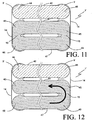
FIG. 11 is another plan view showing two separate fluid circuits within a heat exchanger according to some embodiments of the invention. -
FIG. 12 is another plan view showing two separate fluid circuits within a heat exchanger according to some embodiments of the invention. -
FIG. 13 is a front view showing two separate fluid circuits within a heat exchanger according to some embodiments of the invention. -
FIG. 14 is a front view showing a single fluid circuit within a heat exchanger according to some embodiments of the invention. - Before any embodiments of the invention are explained in detail, it is to be understood that the invention is not limited in its application to the details of construction and the arrangement of components set forth in the following description or illustrated in the accompanying drawings. The invention is capable of other embodiments and of being practiced or of being carried out in various ways. Also, it is to be understood that the phraseology and terminology used herein is for the purpose of description and should not be regarded as limiting. The use of "including," "comprising," or "having" and variations thereof herein is meant to encompass the items listed thereafter and equivalents thereof as well as additional items. Unless specified or limited otherwise, the terms "mounted," "connected," "supported," and "coupled" and variations thereof are used broadly and encompass both direct and indirect mountings, connections, supports, and couplings. Further, "connected" and "coupled" are not restricted to physical or mechanical connections or couplings.
- A
heat exchanger 1 according to an embodiment of the invention is depicted inFIG. 1 , and includes aheat exchange core 2 bounded between twoside plates 4. Theheat exchange core 2 is constructed as a stacked and brazed assembly of alternating layers offlat tubes 5 and corrugated fins 6, as shown in the core detail ofFIG. 2 . Thetubes 5 and fins 6 are preferably formed of an aluminum alloy so that theheat exchanger 1 can be built to be lightweight and highly efficient in the transfer of heat between a first fluid flowing through the interiors of thetubes 5 and a second fluid (air, for example) passing through the corrugations of the fins 6. Such aheat exchanger 1 can be used as, for example, a vehicular powertrain cooling heat exchanger to cool engine oil, transmission oil, engine coolant, or some other fluid from which dissipation of heat is desired. - Open ends of the
tubes 5 are received intoheaders 3 arranged at opposing ends of theheat exchanger 1. Eachheader 3 is an assembly of parts, shown in exploded view inFIG. 3 . Theheader 3 includes an extrudedsection 7 that extends over generally the full stacked height of theheat exchange core 2, and provides a number ofcylindrical fluid manifolds 8 that distribute the first fluid to, or receive the first fluid from, the array oftubes 5. The number ofcylindrical fluid manifolds 8 that is provided by eachextruded section 7 corresponds to the number oftubes 5 provided in each row of tubes of the core 2 (e.g. two, in the exemplary embodiment ofFIGs. 1-5 ). - As best seen in the cross-sectional view of
FIG. 5 , each of thecylindrical fluid manifolds 8 is bounded by anarcuate wall section 9 over a majority of the circular periphery of the manifold, with thatarcuate wall section 9 having a generally constant wall thickness (indicated by the reference number 20). On the core-facing side ofheader 3, thearcuate wall sections 9 of the twoadjacent manifolds 8 merge together. On the opposing (i.e. the non-core-facing) side of the header 3a planarouter surface 14 of the header is provided. The planarouter surface 14, together with thecylindrical manifolds 8, bounds a thickenedwall section 21 of the extrudedsection 7. The thickenedwall section 21 has a generally triangular cross-section, as indicated inFIG. 5 by the dashed triangle 22), with a wall thickness that is substantially greater than thewall thickness 20 of thearcuate wall sections 9. As indicated byFIG. 5 , the cross-section of the thickenedwall section 21 can deviate somewhat from a truly triangular shape while still exhibiting a generally triangular cross-section. -
Tube slots 13 are provided along the lengths of theheaders 3 to receive the ends of thetubes 5 into the correspondingcylindrical fluid manifolds 8. Thetube slots 13 can be formed into the extrudedsection 7 by, for example, saw-cutting or piercing. Each of thetube slots 13 extends through one of thearcuate wall sections 9, and has a width and height that generally corresponds to the major and minor dimensions of theflat tubes 5. The ends of theflat tubes 5 are preferably inserted into thetube slots 13 after theflat tubes 5 and the fins 6 have been stacked to form thecore 2, so that thetubes 5 can be brazed to theheaders 3 in the same brazing operation as is used to join theflat tubes 5 to the fins 6, thereby creating leak-free joints at the tube-to-header interfaces. - The
cylindrical fluid manifolds 8 are hydraulically connected by way of one ormore apertures 15 that extend through the thickenedwall section 21 at one or more locations along the length of theheader 3. Such anaperture 15 can be formed by a machining operation such as drilling or milling through theplanar surface 14 to a predetermined depth, in which case the forming of theaperture 15 can define acircular opening 40 in theplanar surface 14, as shown inFIG. 3 . The predetermined depth is selected to be less than the depth that would be required in order to remove all of the material separating thecylindrical fluid manifolds 8 at that location. As best seen in the cross-sectional view ofFIG. 4 , theaperture 15 of the exemplary embodiment has the material in the thickenedwall section 21 removed to a depth, as measured from theplanar surface 14, that is approximately equal to the radius of thearcuate wall sections 9. While the exemplary embodiment depicts acircular opening 40 formed in the planarouter surface 14, it should be understood that other machining methods might result in non-circular openings. - A
plug 12 can be inserted into theopening 40 defined by the forming of theaperture 15 at the planarouter surface 14 in order to provide a fluid-tight seal between thefluid manifolds 8 and the outside environment external to theheader 3. Theplug 12 includes aninsertion portion 18 with a profile that generally matches theopening 40 created in theplanar surface 14, so that theplug 12 can be partially inserted into thatopening 40 with minimal clearance between side surfaces of theinsertion portion 18 and theopening 40. Aperipheral flange portion 17 extends beyond the outer periphery of theinsertion portion 18 by an amount sufficient to engage and bear upon theplanar surface 14 surrounding theopening 40, thereby limiting the insertion depth of theplug 12. In some especially preferable embodiments, such as the exemplary embodiment ofFIG. 4 , the height of the insertion portion 18 (and, therefore, the depth of insertion of theplug 12 into the opening 40) is approximately equal to thewall thickness 20 of thearcuate wall sections 9. - A
groove 25 can be provided in the face of theperipheral flange portion 17 that is disposed against theplanar surface 14, and can be used to accommodate a ring ofbraze material 16. Theplug 12, along with the ring ofbraze material 16, can be assembled to the extrudedsection 7 prior to brazing of theheat exchanger 1, so that theplug 12 can be secured into theheader 3 during the brazing operation. In some embodiments it may be more preferable to instead use a braze foil, braze paste, or clad braze layer on either theplug 12 or the extrudedsection 7, in which case thebraze ring 16 and thegroove 25 may be eliminated. - One or more of the
plugs 12 can be provided with anintegral mounting pin 19 extending outwardly away from the header in a direction perpendicular to the planarouter surface 14. The integral mounting pins 19 can be accommodated into corresponding holes of other components to which theheat exchanger 1 is to be assembled in order to, for example, secure theheat exchanger 1 within a cooling module. Annular vibration isolators can be conveniently assembled over the mountingpin 19 and bear against theperipheral flange portion 17 of theplug 12. - At the ends of the
header 3, thecylindrical fluid conduits 8 are sealed with eitherend caps 11 orfluid ports 10. In the exemplary embodiment ofFIG. 1 , each of theheaders 3 is provided with threeend caps 11 and onefluid port 10, so that the fluid to be cooled within theheat exchanger 1 can be received into one of the headers 3 (the inlet header) through itsfluid port 10 and can be removed from the other one of the headers 3 (the outlet header) through itsfluid port 10. Although the fluid is directly received into only one of thecylindrical fluid manifolds 8 of theinlet header 3, theapertures 15 provided in thatheader 3 allow at least some of the fluid to pass into the adjacentcylindrical fluid manifold 8 so that theflat tubes 5 connected to each of thosefluid manifolds 8 are placed hydraulically in parallel with one another. In similar fashion, the fluid received into that one of thecylindrical fluid manifolds 8 of theoutlet header 3 can be transferred by way of theapertures 15 into thecylindrical fluid manifold 8 having theoutlet port 10. - By placing multiple
fluid manifolds 8 in hydraulic parallel, the present invention is able to provide a more robust design for applications wherein the fluid to be cooled is at an elevated pressure. The ability of the fluid manifold to withstand the elevated internal pressures imposed by the fluid is increased by reducing the diameter of each fluid manifold, without sacrificing the total flow area provided by theflat tubes 5. To that end, it should be understood that the number ofcylindrical fluid manifolds 8 that may be provided in each of theheaders 3 is not limited to two.Additional fluid manifolds 8 can be provided, and can be fluidly connected to adjacent fluid manifolds throughadditional apertures 15. It should be understood that a multipass heat exchanger can also be provided by placingapertures 15 between some, but not all, of theadjacent fluid manifolds 8. - As one non-limiting example of a heat exchanger having more than two cylindrical fluid manifolds within the headers, a portion of a heat exchanger 1' is depicted in
FIGs. 6-7 . The heat exchanger 1' includes a heat exchange core 2' that is substantially similar to theheat exchange core 2 depicted inFIG. 2 , except that three rows offlat tubes 5 are provided in each layer of tubes. Similarly, a header 3' provided at either end of the core 2' (only a single header is shown) includes an extruded section 7' that includes threecylindrical fluid manifolds 8 arranged side-by-side to receive the ends of thetubes 5 in similar fashion as was described previously with reference to the embodiment ofFIG. 1 . - The extruded section 7', shown in greater detail in
FIG. 8 , is similar to the previously describedextruded section 7 in that it includes anarcuate wall section 9 over a majority of the circular periphery of each manifold 8, with thearcuate wall sections 9 having a generally constant wall thickness. The ends of thetubes 5 are received into the fluid manifold through slots provided in thosearcuate wall sections 9. A planarouter surface 14 is again provided on the opposing (i.e. the non-core-facing) side of the header 3'. - The extruded header section 7' can optionally be provided with mounting
flanges 33, as shown inFIGs. 6-8 . The mountingflanges 33 extend in a direction that is perpendicular to theplanar surface 14 and is directed away from theheat exchange core 2, thereby defining a pair of mounting planes 35 (i.e. a first mountingplane 35 and a second mounting plane 35) for the heat exchanger 1' which are likewise arranged perpendicular to theplanar surface 14. In some preferred embodiments thecylindrical fluid manifolds 8 provided by the header 3' are all located entirely between the pair of mountingplanes 35. While the mountingflanges 33 are depicted as extending from thearcuate wall sections 9, it should be understood that they can alternatively or in addition extend from theplanar surface 14. - The mounting
flanges 33 can be used to structurally mount the heat exchanger 1' into a cooling module or other assembly, as shown inFIGs. 6-7 . A U-channel 23 that forms part of the cooling module or other assembly includes parallel, spaced-apart legs 27 joined by a connectingsection 26, with the space between thelegs 27 sized to be sufficiently large to allow for the header 3' to be received there between.Connection assemblies 24 structurally connect the header 3' to the U-channel 23, and includecompressible rubber isolators 32 that are inserted into holes placed within the U-channel 23 so that a portion of each isolator 32 is arranged inside of the U-channel 23 and another portion of theisolator 32 is arranged outside of theU-channel 23. Theisolators 32 are provided in pairs at locations that align with corresponding mountingholes 34 provided in theflanges 33, so that abolt 28 or other similar fastener can be inserted through the pairedisolators 32 and the corresponding mountingholes 34 in theflanges 33.Washers 31 are provided between ahead 29 of thebolt 28 and one of the paired isolators and between anut 30 that is threaded onto the end of thebolt 28 and the other one of the paired isolators. Each of the connection assemblies thus includes abolt 28,nut 30, pair ofwashers 31, and pair ofisolators 32. By tightening thenuts 30 of theconnection assemblies 24, the heat exchanger 1' can be secured to theU-channel 23. It should be understood that theconnection assemblies 24 can be used either as an alternative to, or in addition to, the mountingpins 19 that were previously described. - In some embodiments, such as the ones shown in
FIGs. 9-12 , it may be desirable to incorporate fluid circuits for multiple fluids to be cooled within asingle heat exchanger 1, 1'. In such an embodiment, afirst series 41 of theflat tubes 5 is used to convey a first one of the fluids to be cooled, while asecond series 42 of theflat tubes 5 is used to convey a second one of the fluids to be cooled. As shown inFIG. 9 , each of theheaders 3 arranged at opposing ends of theheat exchanger 1 again includes a pair ofcylindrical fluid manifolds 8. However, thefluid manifolds 8 within aheader 3 can be hydraulically isolated from one another, thereby providing a fluid manifold for the first fluid in each header 3 (themanifolds 43, 45) and additionally a fluid manifold for the second fluid in each header 3 (themanifolds 44, 46). - The number of separate fluid flow circuits provided in a given heat exchanger is not limited. Additional rows of tubes can be added, such as by using the previously described headers 3' having three
cylindrical fluid manifolds 8 to provide a three-fluid heat exchanger 1', as shown inFIG. 10 . Such a heat exchanger includes athird series 47 of theflat tubes 5, which extends between additionalfluid manifolds - As shown in
FIGs. 11 and 12 , the number of tube rows or series can also be increased without increasing the number of discrete fluids being cooled within the heat exchanger. In the embodiment ofFIG. 11 , theadditional series 47 is used to provide additionalflat tubes 8 for conveying the first fluid through the heat exchanger. The previously describedapertures 15 are provided between thecylindrical manifolds cylindrical manifolds series 41 offlat tubes 5 fluidly in parallel with theseries 47 offlat tubes 5. Such an arrangement can be especially desirable when the flow area required for the first fluid is substantially greater than the flow area required for the second fluid. - As shown in
FIG. 12 , in some cases it may be more desirable to provide theapertures 15 in only one of theheaders 3, thereby placing theseries 41 offlat tubes 5 fluidly in series with theseries 47 offlat tubes 5. As indicated by the arrow inFIG. 12 , the first fluid is first received into thecylindrical fluid manifold 48, passes through theseries 47 of tubes to thecylindrical fluid manifold 49, transfers by way of one ormore apertures 15 to thecylindrical fluid manifold 45, and passes through theseries 41 of tubes to thecylindrical fluid manifold 43. More effective heat transfer between the air passing through the heat exchanger and the first fluid can be achieved with such an arrangement. - Additional flow circuiting options can also be achieved through the use of
baffles 53 inserted into one or bothheaders 3, 3', as shown inFIGs. 13 and 14 . Such afluid baffle 53 can serve to separate a singlecylindrical fluid manifold 8 into two separate fluid manifolds (e.g. 43 and 51, 45 and 52), as depicted. Aseries 41 offlat tubes 5 and aseries 50 offlat tubes 5 are thereby arranged within the same row of tubes of the heat exchanger. Such an arrangement can provide yet another alternative method by which multiple fluids can be accommodated within a single heat exchanger in an optimized fashion when the flow area requirements for each of the fluids is vastly different. Specifically, the location of thebaffles 53 along the length of theheaders 3, 3' can be selected so that the total number oftubes 5 within the row is appropriately divided between theseries 41 and theseries 50. Additionally, one or more additional rows of flat tubes can be provided for one or more additional fluids, as was described with reference toFIGs. 9 and 10 . - In addition, the flow circuiting of
FIG. 9 ,FIG. 11 , andFIG. 13 can be combined within asingle heat exchanger 1 to provide even greater flexibility. By way of example, such a heat exchanger can have two or more sets of tubes such as thesets header 3 arranged at each end of the heat exchanger to communicate withcylindrical fluid manifolds 8. A third set of tubes can be arranged in a common row with one of the first two sets of tubes, such as is shown inFIG. 13 for thesets manifolds apertures 15, so that the same fluid flows in parallel through two different sets of tubes, with one the sets of tubes being arranged in a common row as another set of tubes for another fluid. In this manner, one of the fluids can be transported through the heat exchanger by all of theflat tubes 5 of one of the sets of tubes, and by some, but not all, of theflat tubes 5 of another one of the sets of tubes. Such an arrangement can be especially desirable when the number of tubes necessary (for example, due to heat transfer considerations or pressure drop considerations or both) for one of the fluids is substantially greater than the number of tubes necessary for another one of the fluids. - It should be understood that the various embodiments depicted in
FIGs. 9-14 are depicted in simplified form, and that structural details of the heat exchangers that have been excluded from those figures may still be present. Particularly, it should be understood that any or all of the previously described features, including theplugs 12, mountingpins 19, and mountingflanges 33, can be included in any of those embodiments. - Various alternatives to the certain features and elements of the present invention are described with reference to specific embodiments of the present invention. With the exception of features, elements, and manners of operation that are mutually exclusive of or are inconsistent with each embodiment described above, it should be noted that the alternative features, elements, and manners of operation described with reference to one particular embodiment are applicable to the other embodiments.
- The embodiments described above and illustrated in the figures are presented by way of example only and are not intended as a limitation upon the concepts and principles of the present invention. As such, it will be appreciated by one having ordinary skill in the art that various changes in the elements and their configuration and arrangement are possible without departing from the spirit and scope of the present invention.
Claims (20)
- A heat exchanger comprising:a first plurality of flat tubes to convey a first fluid through the heat exchanger;a second plurality of flat tubes to convey a second fluid through the heat exchanger;a first header arranged at an end of the heat exchanger, the first header including a first cylindrical fluid manifold having a plurality of tube slots extending through a first arcuate wall section of the first header, a second cylindrical fluid manifold extending parallel and adjacent to the first cylindrical fluid manifold having a plurality of tube slots extending through a second arcuate wall section of the first header, and a thickened wall section bounded by the first cylindrical fluid manifold, the second cylindrical fluid manifold, and a planar outer surface of the first header, the thickened wall section having a generally triangular cross-section; anda second header arranged at an opposing end of the heat exchanger, the second header including a third cylindrical fluid manifold having a plurality of tube slots extending through a first arcuate wall section of the second header, a fourth cylindrical fluid manifold extending parallel and adjacent to the third cylindrical fluid manifold having a plurality of tube slots extending through a second arcuate wall section of the second header, and a thickened wall section bounded by the third cylindrical fluid manifold, the fourth cylindrical fluid manifold, and a planar outer surface of the second header, the thickened wall section having a generally triangular cross-section;wherein tube ends of the first plurality of tubes are received through the tube slots extending through the first arcuate wall sections of both the first and second header, and wherein tube ends of the second plurality of flat tubes are received through the second arcuate wall sections of both the first and second headers.
- The heat exchanger of claim 1, further comprising a third plurality of flat tubes to convey the first fluid through the heat exchanger, the first header additionally including a fifth cylindrical fluid manifold extending parallel and adjacent to the first cylindrical fluid manifold having a plurality of tube slots extending through a third arcuate wall section of the first header, and the second header additionally including a sixth cylindrical fluid manifold extending parallel and adjacent to the third cylindrical fluid manifold having a plurality of tube slots extending through a third arcuate wall section of the second header, the first header having another thickened wall section with a generally triangular cross-section bounded by the first fluid manifold, the fifth fluid manifold, and the planar outer surface of the first header, and the second header having another thickened wall section with a generally triangular cross-section bounded by the third fluid manifold, the sixth fluid manifold, and the planar outer surface of the second header.
- The heat exchanger of claim 2, wherein the first and the third pluralities of tubes define two sequentially arranged flow passages through the heat exchanger for the first fluid.
- The heat exchanger of claim 2, wherein the second header includes an aperture extending through the thickened wall section between the third fluid manifold and the sixth fluid manifold in order to fluidly couple the first and the third pluralities of tubes.
- The heat exchanger of claim 4, wherein the first header includes an aperture extending through the thickened wall section between the first fluid manifold and the fifth fluid manifold in order to fluidly couple the first and the third pluralities of tubes.
- The heat exchanger of claim 2, wherein the tubes of the first plurality of tubes are hydraulically in parallel with the tubes of the third plurality of tubes.
- The heat exchanger of claim 1, further comprising a third plurality of flat tubes to convey a fluid through the heat exchanger, the first header additionally including a fifth cylindrical fluid manifold extending concentrically with the first cylindrical fluid manifold having a plurality of tube slots extending through the first arcuate wall section of the first header, and the second header additionally including a sixth cylindrical fluid manifold extending concentrically with the third cylindrical fluid manifold having a plurality of tube slots extending through the first arcuate wall section of the second header, the first header having another thickened wall section with a generally triangular cross-section bounded by the fifth fluid manifold, the second fluid manifold, and the planar outer surface of the first header, and the second header having another thickened wall section with a generally triangular cross-section bounded by the sixth fluid manifold, the fourth fluid manifold, and the planar outer surface of the second header.
- The heat exchanger of claim 7, wherein the third fluid manifold and the sixth fluid manifold are in direct fluid communication with one another so that the first fluid flows sequentially through the first and the third pluralities of tubes.
- The heat exchanger of claim 7, wherein the second header includes an aperture extending through the thickened wall section between the fourth fluid manifold and the sixth fluid manifold in order to fluidly couple the second and the third pluralities of tubes.
- The heat exchanger of claim 9, further comprising a plug inserted into an opening extending through the planar outer surface to the aperture.
- The heat exchanger of claim 9, wherein the first header includes an aperture extending through the thickened wall section between the second fluid manifold and the fifth fluid manifold in order to fluidly couple the second and the third pluralities of tubes.
- The heat exchanger of claim 11, further comprising a first plug inserted into an opening extending through the planar outer surface of the first header to the aperture in the first header, and a second plug inserted into an opening extending through the planar outer surface of the second header to the aperture in the second header.
- A header for a heat exchanger, comprising:a plurality of parallel arranged cylindrical fluid manifolds;a plurality of arcuate wall sections having a constant wall thickness, each of the arcuate wall sections corresponding to one of the plurality of cylindrical fluid manifolds and each having a plurality of tube slots extending through the constant wall thickness to the corresponding fluid manifold; andone or more thickened wall sections bounded by two adjacent ones of the plurality of cylindrical fluid manifolds and a planar outer surface of the header, the one or more thickened wall sections each having a generally triangular cross-section.
- The header of claim 13, further comprising one or more apertures extending through the one or more thickened wall sections to provide a fluid communication pathway between those cylindrical fluid manifolds bounding the one or more thickened wall sections.
- The header of claim 14, further comprising one or more plugs in one-to-one correspondence with the one or more apertures, each plug inserted into an opening extending through the planar outer surface to the corresponding aperture.
- The header of claim 15, wherein a portion of each of the one or more plugs is brazed to the outer planar surface.
- The header of claim 15, wherein at least some of said plugs includes a mounting pin integral with the plug and extending outwardly from the header in a direction perpendicular to the planar outer surface.
- The header of claim 15, wherein an insertion depth of each of the one or more plugs is equal to the constant wall thickness of the arcuate wall sections.
- The header of claim 13, further comprising:a first mounting flange extending from the header and defining a first mounting plane;a first mounting hole extending through the first mounting flange;a second mounting flange extending from the header and defining a second mounting plane parallel to the first mounting plane; anda second mounting hole extending through the second mounting flange and aligned with the first mounting hole, wherein the first and second mounting planes are oriented perpendicular to the planar outer surface of the header.
- The header of claim 19, wherein the plurality of parallel arranged cylindrical fluid manifolds is entirely located between the first and second mounting planes.
Applications Claiming Priority (1)
| Application Number | Priority Date | Filing Date | Title |
|---|---|---|---|
| US15/628,953 US20170370658A1 (en) | 2016-06-23 | 2017-06-21 | Heat Exchanger and Header for the Same |
Publications (1)
| Publication Number | Publication Date |
|---|---|
| EP3418667A1 true EP3418667A1 (en) | 2018-12-26 |
Family
ID=62748670
Family Applications (1)
| Application Number | Title | Priority Date | Filing Date |
|---|---|---|---|
| EP18000540.7A Withdrawn EP3418667A1 (en) | 2017-06-21 | 2018-06-20 | Heat exchanger and header for the same |
Country Status (1)
| Country | Link |
|---|---|
| EP (1) | EP3418667A1 (en) |
Cited By (1)
| Publication number | Priority date | Publication date | Assignee | Title |
|---|---|---|---|---|
| EP3809090A1 (en) * | 2019-10-18 | 2021-04-21 | Valeo Autosystemy SP. Z.O.O. | A connection assembly |
Citations (5)
| Publication number | Priority date | Publication date | Assignee | Title |
|---|---|---|---|---|
| EP0825404A2 (en) * | 1996-08-12 | 1998-02-25 | Calsonic Corporation | Integral-type heat exchanger |
| WO2003016812A1 (en) * | 2001-08-13 | 2003-02-27 | Norsk Hydro Asa | A heat exchanger and a manufacturing method for said heat exchanger |
| DE10150213A1 (en) * | 2001-10-12 | 2003-05-08 | Erbsloeh Aluminium Gmbh | Extruded profile, particularly for heat exchanger, is preferably of aluminum or aluminum alloy and comprises at least two tubes with equal or different geometry joined to each other by ribs |
| KR20090120078A (en) * | 2008-05-19 | 2009-11-24 | 주식회사 두원공조 | Header of high pressure heat exchanger |
| EP2345861A2 (en) * | 2010-01-15 | 2011-07-20 | Hamilton Sundstrand Corporation | Heat exchanger with extruded multi-chamber manifold with machined bypass |
-
2018
- 2018-06-20 EP EP18000540.7A patent/EP3418667A1/en not_active Withdrawn
Patent Citations (5)
| Publication number | Priority date | Publication date | Assignee | Title |
|---|---|---|---|---|
| EP0825404A2 (en) * | 1996-08-12 | 1998-02-25 | Calsonic Corporation | Integral-type heat exchanger |
| WO2003016812A1 (en) * | 2001-08-13 | 2003-02-27 | Norsk Hydro Asa | A heat exchanger and a manufacturing method for said heat exchanger |
| DE10150213A1 (en) * | 2001-10-12 | 2003-05-08 | Erbsloeh Aluminium Gmbh | Extruded profile, particularly for heat exchanger, is preferably of aluminum or aluminum alloy and comprises at least two tubes with equal or different geometry joined to each other by ribs |
| KR20090120078A (en) * | 2008-05-19 | 2009-11-24 | 주식회사 두원공조 | Header of high pressure heat exchanger |
| EP2345861A2 (en) * | 2010-01-15 | 2011-07-20 | Hamilton Sundstrand Corporation | Heat exchanger with extruded multi-chamber manifold with machined bypass |
Cited By (1)
| Publication number | Priority date | Publication date | Assignee | Title |
|---|---|---|---|---|
| EP3809090A1 (en) * | 2019-10-18 | 2021-04-21 | Valeo Autosystemy SP. Z.O.O. | A connection assembly |
Similar Documents
| Publication | Publication Date | Title |
|---|---|---|
| EP2962355B1 (en) | Heat transfer device for batteries | |
| US20130264039A1 (en) | Heat exchanger assembly and method | |
| US6170567B1 (en) | Heat exchanger | |
| CN107614999B (en) | Heat exchanger and heat exchanger case | |
| KR19990022246A (en) | heat transmitter | |
| US20170370658A1 (en) | Heat Exchanger and Header for the Same | |
| CA2635593C (en) | Multi-fluid heat exchanger arrangement | |
| EP2583046A1 (en) | A plate type heat exchanger, an oil cooling system and a method for cooling oil | |
| US20200395644A1 (en) | Battery cooling system | |
| US20190178589A1 (en) | Internal degas feature for plate-fin heat exchangers | |
| EP3418667A1 (en) | Heat exchanger and header for the same | |
| US11105557B2 (en) | Heat exchanger, tank for heat exchanger, and method of making the same | |
| CN210464171U (en) | Collecting pipe assembly and pipe belt type oil cooler | |
| EP2064507B1 (en) | A plate heat exchanger | |
| CN211012553U (en) | Heat exchanger | |
| RU2540030C2 (en) | Assembled plate-type heat exchanger | |
| US11965700B2 (en) | Heat exchanger for cooling multiple fluids | |
| US20220026159A1 (en) | Heat exchanger for cooling multiple fluids | |
| CN115900401A (en) | Heat exchanger | |
| JP2004077114A (en) | Integrated heat exchange device |
Legal Events
| Date | Code | Title | Description |
|---|---|---|---|
| PUAI | Public reference made under article 153(3) epc to a published international application that has entered the european phase |
Free format text: ORIGINAL CODE: 0009012 |
|
| AK | Designated contracting states |
Kind code of ref document: A1 Designated state(s): AL AT BE BG CH CY CZ DE DK EE ES FI FR GB GR HR HU IE IS IT LI LT LU LV MC MK MT NL NO PL PT RO RS SE SI SK SM TR |
|
| AX | Request for extension of the european patent |
Extension state: BA ME |
|
| STAA | Information on the status of an ep patent application or granted ep patent |
Free format text: STATUS: THE APPLICATION IS DEEMED TO BE WITHDRAWN |
|
| 18D | Application deemed to be withdrawn |
Effective date: 20190627 |