EP2064498B1 - Ice dispenser - Google Patents
Ice dispenser Download PDFInfo
- Publication number
- EP2064498B1 EP2064498B1 EP07802795A EP07802795A EP2064498B1 EP 2064498 B1 EP2064498 B1 EP 2064498B1 EP 07802795 A EP07802795 A EP 07802795A EP 07802795 A EP07802795 A EP 07802795A EP 2064498 B1 EP2064498 B1 EP 2064498B1
- Authority
- EP
- European Patent Office
- Prior art keywords
- ice
- slide
- fingers
- ice dispenser
- dispenser according
- Prior art date
- Legal status (The legal status is an assumption and is not a legal conclusion. Google has not performed a legal analysis and makes no representation as to the accuracy of the status listed.)
- Not-in-force
Links
Images


Classifications
-
- F—MECHANICAL ENGINEERING; LIGHTING; HEATING; WEAPONS; BLASTING
- F25—REFRIGERATION OR COOLING; COMBINED HEATING AND REFRIGERATION SYSTEMS; HEAT PUMP SYSTEMS; MANUFACTURE OR STORAGE OF ICE; LIQUEFACTION SOLIDIFICATION OF GASES
- F25C—PRODUCING, WORKING OR HANDLING ICE
- F25C5/00—Working or handling ice
- F25C5/20—Distributing ice
- F25C5/22—Distributing ice particularly adapted for household refrigerators
-
- F—MECHANICAL ENGINEERING; LIGHTING; HEATING; WEAPONS; BLASTING
- F25—REFRIGERATION OR COOLING; COMBINED HEATING AND REFRIGERATION SYSTEMS; HEAT PUMP SYSTEMS; MANUFACTURE OR STORAGE OF ICE; LIQUEFACTION SOLIDIFICATION OF GASES
- F25D—REFRIGERATORS; COLD ROOMS; ICE-BOXES; COOLING OR FREEZING APPARATUS NOT OTHERWISE PROVIDED FOR
- F25D23/00—General constructional features
- F25D23/12—Arrangements of compartments additional to cooling compartments; Combinations of refrigerators with other equipment, e.g. stove
- F25D23/126—Water cooler
Definitions
- the present invention relates to an ice dispenser, in particular an ice dispenser of the type which can be used in a refrigeration device to temporarily store pieces of ice produced by an automatic ice maker of the refrigeration device and output at the request of a user.
- a known ice dispenser comprises a storage container for ice pieces, a stirring tool which is rotatable about an axis extending through the reservoir, an output chamber which extends the reservoir in the direction of the axis, and a rotatable slide coupled in the output chamber to the stirring tool in the form of a plurality blades mounted in parallel on the axle, which, in the course of its rotation, convey ice that has entered the discharge chamber to an exit opening.
- the stirring tool is formed on a part of its length as a helix and on another, the output chamber adjacent part as a screw conveyor, so that by a rotation of the stirring ice pieces are conveyed into the discharge chamber.
- a very powerful drive motor for the stirring tool can be provided, and reservoir and stirring tool can be designed with high mechanical strength to allow breakage of the pieces of ice even after prolonged disuse.
- this approach is associated with considerable costs, and there is a risk that pieces of ice in the reservoir are undesirably crushed .
- U.S. 4,846,381 proposes to solve the problem of freezing by a stirring device and a screw conveyor are mounted in the reservoir of an ice dispenser, separated from each other and each driven by its own motor.
- the stirring tool can be actuated to separate the ice pieces from each other, without at the same time is issued by the screw auger ice.
- a problem of this design is the large space requirement of the stirring tool and the separate screw conveyor and its drive motors, which makes this solution mainly for commercial, exclusively for ice making devices interesting.
- Another ice dispenser according to the preamble of claim 1 is made US 4972999 known.
- Object of the present invention is to provide an ice dispenser, which reliably prevents the freezing of stored pieces of ice and thereby has a compact, inexpensive realizable structure that makes it suitable in particular for use in a household refrigerator.
- the object is achieved by providing in an ice dispenser with a storage container for pieces of ice, a rotatable about an axis extending through the reservoir agitator, an adjacent to the reservoir discharge chamber and a coupled in the output chamber to the agitator rotatable slide, wherein on a wall of the Output chamber in which the slider moves in its rotation, an output opening is formed for conveyed by the slide ice between the stirring tool and slide a clutch is arranged to selectively transmit or not transmit a force exerted on the agitator driving torque to the slider.
- the slider rotates together with the agitating tool and pieces of ice, which enter the dispensing chamber by the movement of the agitating tool or otherwise, are conveyed from the slider to the dispensing opening. If the drive torque is not transmitted, the slider remains at rest, so that the ice is not conveyed to the discharge port. In this state, it is possible to operate the stirring tool alone to disengage pieces of ice collapsing in the hopper without giving up ice at the same time.
- an ice dispenser is preferred in which the agitating tool and the slider have the same axis of rotation.
- the discharge chamber expediently has the shape of a cylinder concentric with the axis of rotation of the slide, the discharge opening being formed in a lateral surface of the cylinder.
- an end face of the cylindrical dispensing chamber is open to the reservoir.
- a partition with a passage opening is arranged between the reservoir and the discharge chamber.
- the size of the port may be selected to suitably control the rate at which pieces of ice enter the dispensing chamber from the hopper when the agitator is agitated.
- the slider can be fixed in a position blocking the passage opening.
- the reservoir In order to promote the movement of the ice cubes from the reservoir into the dispensing chamber, the reservoir preferably has a bottom sloping towards the dispensing chamber.
- the slider comprises a first set of fingers and that a second set of fingers is provided in the dispensing chamber, at least one of the sets comprising at least two axially spaced fingers, and that upon rotation of the slider one finger of the other set a space between the two fingers of the one sentence happens.
- Pieces of ice between the two sets of fingers are crushed between the fingers and thus come in the form of small fragments to the discharge opening.
- the fingers are expediently designed as a knife, with sharp cutting edges.
- the second set of fingers can be fixed in a position bridging the dispensing opening, in particular in the above-mentioned first embodiment without a partition between the reservoir and the dispensing chamber.
- the second set of fingers in the dispensing opening bridging position closes them only partially, it can be used in this position to crush the pieces of ice, since the resulting fragments can continue to pass the dispensing opening.
- the second set of fingers is suitably movable between the dispensing opening bridging position and the dispensing opening releasing position.
- the bridging position is a stable equilibrium position of the second set of fingers.
- the second set of fingers is preferably locked at the option of a user in the output chamber or rotatable together with the slider about its axis of rotation.
- Such a rotation can be easily driven when the second set of fingers is frictionally coupled to the slider.
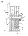
- FIG. 1 shown in a schematic section refrigeration device has a heat-insulating body 1 and a door 2, which define an interior space 3.
- the interior 3 is maintained at a temperature below 0 ° C by an evaporator, which is housed in an upper part of the body 1 divided evaporator chamber 4.
- An automatic ice maker 5 is arranged in the immediate vicinity of the evaporator chamber 4 in the interior 3, so that it can preferably be acted upon by cold air from the evaporator chamber 4.
- the ice maker 5 comprises in a known manner, not shown in detail in the figure, a plurality of mold containers, means for automatically dosing water into the mold containers, and means for automatically ejecting the finished ice cubes from the mold containers.
- a collecting container 6 of an ice dispenser is arranged, which receives the ejected pieces of ice.
- the collecting container 6 extends over a large part of the depth of the inner space 3.
- an electric motor for driving a stirring rod 8 extending in the longitudinal direction of the collecting container 6 is housed.
- Rotary blades 9 of a grinder are coupled to an end 7 of the stirring rod 8 facing away from the niche in a manner which will be described in more detail below.
- the knives 9 are housed in a cylindrical dispensing chamber 10 which is open to the collecting container 6 and extends it along the axis of rotation of the stirring rod 8.
- an electromagnet 11 is arranged, whose function will also be explained later.
- the stirring rod 8 is a metal rod zigzag-shaped in a plane parallel to the axis. Due to its planar shape, unlike a helix or a worm, it exerts no conveying force in the axial direction on pieces of ice contained in the collecting container 6, but moves them in random directions and thus prevents them from freezing over a large area. Therefore, the stirring rod 8 can be rotated from time to time by the motor, without thereby ice pieces are pressed into the discharge chamber 10 and can clog them.
- the output chamber 10 has substantially the shape of a horizontal cylinder, on whose lateral surface a downwardly open discharge opening 12 is formed.
- This discharge opening 12 is located in Fig. 1 shown passage 13 which extends through an insulating material layer of the door 2 and opens into an open towards the outside of the door 2 niche 14.
- a flap 15 keeps the passage 13 closed unless the dispenser is in operation to deliver ice through the dispensing opening 12 and the passage 13 to a container placed in the recess 14.
- a water tank 16 is embedded on the rear wall of the niche 14 in the insulating material of the door 2.
- the water tank 16 is on the one hand as the icemaker 5 via a supply line 17 and a check valve 18 connected to the drinking water network and on the other hand to a tap 19 in the niche 14.
- the rake 8 goes at its end facing away from the niche 7 in one piece into a cylindrical shaft 20, the extends through the discharge chamber 10.
- a distal end portion 21 of the shaft 20 has a non-circular, for example, square cross-sectional shape.
- a sleeve 22, which is mounted so as to be easily rotatable on the shaft 20, carries a plurality of cutting discs 23, each of which, as in FIG Fig. 3 to recognize four of a core portion 24 radially projecting knife 9 carries and act as a slide for located in the discharge chamber 10 pieces of ice.
- sharp-edged plates 26 In the spaces between each two of the cutter discs 23 engage sharp-edged plates 26 of about a quarter-circle shape. Mutually facing edges of the knives 9 and the plates 26 are serrated to selectively produce a high pressure to break up the pieces of ice can.
- the plates 26 are rigidly connected at their outer periphery by two transverse struts 25, 27.
- the two transverse struts 25, 27 bear against the wall of the dispensing chamber 10 on either side of the dispensing opening 12, while the plates 26 bridge the dispensing opening 12.
- the distance between the parallel plates 26 is smaller than the dimensions of the ice pieces, so that pieces of ice that are in the dispensing chamber 10 can not readily pass between the plates 26 through the dispensing opening 12.
- the shaft 20 adjacent edge portions of the plates 26 are each clamped by elastic buffer rings 29 between two cutter discs 23, so that the plates 26 tend to follow a rotation of the blades 9 in the counterclockwise direction, if not, as in Fig. 3 are prevented by a voltage applied to one of the transverse struts 25, 27 latch 28 therefrom.
- the sleeve 22 is rotatably mounted in a bearing opening 30 formed in the end wall of the discharge chamber 10 facing the door 2.
- a coupling body 31 is attached to the non-circular end portion 21 of the shaft 20 and with the help of (in Fig. 2 not shown) electromagnet 11 between the in Fig. 2 shown position in which the knife 9 carrying sleeve 22 and the shaft 20 are freely rotatable against each other, displaceable in a coupling position, in which coupling claws 32 of the sleeve 22 in recesses 33 of the coupling body 31 engage, creating a positive and frictional connection between the shaft 20 and the sleeve 22 is produced.
- the operation of the ice dispenser is as follows: As long as in Fig. 2 shown, the shaft 20 and the sleeve 22 are not coupled to each other, the motor is operated in the niche 7 at predetermined intervals for a short time to break free in the sump collapsing ice pieces and keep moving. In the perspective of Fig. 3 The motor rotates preferably in a counterclockwise direction. A frictional torque transmitted via the bearing from the shaft 20 to the sleeve 22 does not cause the blades 9 to rotate since they are braked by the plates 26 clamped to the buffer rings 29 and blocked by the latch 28. Ice pieces located in the dispensing chamber 10 do not reach the dispensing opening 12 because they can not pass through the plates 26.
- the bar 28 is retracted only as long as necessary so that the leading in the direction of rotation of the two transverse struts 27 can pass through the bolt 28 in the transition to the Broadis output mode. Then, when the bolt 28 engages again in the discharge chamber 10, it blocks, as in Fig.
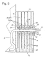
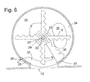
- FIGS. 5 and 6 show the output chamber of an ice dispenser according to a second embodiment of the invention in an axial section, or a section perpendicular to the axis. Elements of this ice dispenser, already with reference to the first embodiment of the Fig. 2 to 4 correspond to explained elements are provided with the same reference numerals and will not be explained again.
- the shaft 20 extends through an intermediate wall 34, which separates the collecting container 6 and the discharge chamber 10 from each other.
- a through hole 35 (see Fig. 6 ) in the intermediate wall 34 allows the passage of ice pieces from the collecting container 6 in the discharge chamber 10 when the stirring rod 8 rotates.
- the stirring rod 8 sweeps next to the intermediate wall 34 closely over the sloping to the intermediate wall 34 bottom of the collecting container 6, so that 6 pieces of ice reliably detected at low level of the collecting container and raised to the through hole 35 so that they through this into the discharge chamber 10 can fall.
- the in the output chamber 10 by means of the electromagnet 11 to the rotation of the stirring rod 8 can be coupled knife 9 have the same shape as in FIGS. 3 and 4 shown.
- the wide plates 26 are replaced by knives 36 whose width is not substantially different from that of the rotating knives 9. They each start from one of the two transverse struts 27 and are slidably clamped with their tips between elastic rings 29 rotating with the knives 9.
- the two transverse struts 27 are connected by the intermediate wall 34 and a front wall of the discharge chamber 10 adjacent sheets 37.
Abstract
Description
Die vorliegende Erfindung betrifft einen Eisspender, insbesondere einen Eisspender des Typs, der in einem Kältegerät einsetzbar ist, um von einem automatischen Eisbereiter des Kältegerätes erzeugte Eisstücke zwischenzulagern und auf Verlangen eines Benutzers auszugeben.The present invention relates to an ice dispenser, in particular an ice dispenser of the type which can be used in a refrigeration device to temporarily store pieces of ice produced by an automatic ice maker of the refrigeration device and output at the request of a user.
Ein aus
Um dieser Gefahr entgegenzuwirken, kann ein sehr kräftiger Antriebsmotor für das Rührwerkzeug vorgesehen werden, und Vorratsbehälter und Rührwerkzeug können mit hoher mechanischer Belastbarkeit ausgelegt werden, um ein Losbrechen der Eisstücke auch nach längerem Nichtgebrauch zu ermöglichen. Auf diese Weise lässt sich zwar die Gefahr einer Blockierung des Eisspenders verringern bzw. die Zeit des Nichtgebrauchs, nach der eine Blockade eintritt, verlängern, doch ist dieser Ansatz mit erheblichen Kosten verbunden, und es besteht die Gefahr, dass Eisstücke im Vorratsbehälter unerwünscht zerkleinert werden. Je größer jedoch der Anteil an kleinen Bruchstücken an dem Eis des Vorratsbehälters ist, um so größer ist dessen Neigung, festzufrieren, und um so größer wird auch die zum Losbrechen des Eises erforderliche Kraft.To counteract this danger, a very powerful drive motor for the stirring tool can be provided, and reservoir and stirring tool can be designed with high mechanical strength to allow breakage of the pieces of ice even after prolonged disuse. In this way, although the risk of blocking the ice dispenser or reduce the time of disuse, after which a blockage occurs extend, but this approach is associated with considerable costs, and there is a risk that pieces of ice in the reservoir are undesirably crushed , However, the larger the proportion of small fragments on the ice of the Reservoir is, the greater is its tendency to freeze, and the greater the force required to break the ice.
Ein weiterer Eisspender gemäß dem Oberbegriff von Anspruch 1 ist aus
Another ice dispenser according to the preamble of claim 1 is made
Aufgabe der vorliegenden Erfindung ist, einen Eisspender zu schaffen, der das Festfrieren von gespeicherten Eisstücken zuverlässig verhindert und der dabei einen kompakten, kostengünstig realisierbaren Aufbau aufweist, der ihn insbesondere für den Einsatz in einem Haushaltskältegerät geeignet macht.Object of the present invention is to provide an ice dispenser, which reliably prevents the freezing of stored pieces of ice and thereby has a compact, inexpensive realizable structure that makes it suitable in particular for use in a household refrigerator.
Die Aufgabe wird gelöst, indem bei einem Eisspender mit einem Vorratsbehälter für Eisstücke, einem um eine sich durch den Vorratsbehälter erstreckende Achse drehbaren Rührwerkzeug, einer an den Vorratsbehälter angrenzenden Ausgabekammer und einem in der Ausgabekammer an das Rührwerkzeug gekoppelt drehbaren Schieber, wobei an einer Wand der Ausgabekammer, in der sich der Schieber bei seiner Drehung entlangbewegt, eine Ausgabeöffnung für von dem Schieber gefördertes Eis gebildet ist, zwischen Rührwerkzeug und Schieber eine Kupplung angeordnet ist, um ein auf das Rührwerkzeug ausgeübtes Antriebsdrehmoment wahlweise auf den Schieber zu übertragen oder nicht zu übertragen. Wenn das Antriebsmoment übertragen wird, rotiert der Schieber zusammen mit dem Rührwerkzeug, und Eisstücke, die durch die Bewegung des Rührwerkzeugs oder auf andere Weise in die Ausgabekammer gelangen, werden von dem Schieber zur Ausgabeöffnung befördert. Wenn das Antriebsdrehmoment nicht übertragen wird, bleibt der Schieber in Ruhe, so dass das Eis nicht zur Ausgabeöffnung gefördert wird. In diesem Zustand ist es möglich, das Rührwerkzeug allein zu betätigen, um im Vorratsbehälter zusammenfrierende Eisstücke voneinander zu lösen, ohne dass gleichzeitig Eis ausgegeben wird.The object is achieved by providing in an ice dispenser with a storage container for pieces of ice, a rotatable about an axis extending through the reservoir agitator, an adjacent to the reservoir discharge chamber and a coupled in the output chamber to the agitator rotatable slide, wherein on a wall of the Output chamber in which the slider moves in its rotation, an output opening is formed for conveyed by the slide ice between the stirring tool and slide a clutch is arranged to selectively transmit or not transmit a force exerted on the agitator driving torque to the slider. When the drive torque is transmitted, the slider rotates together with the agitating tool and pieces of ice, which enter the dispensing chamber by the movement of the agitating tool or otherwise, are conveyed from the slider to the dispensing opening. If the drive torque is not transmitted, the slider remains at rest, so that the ice is not conveyed to the discharge port. In this state, it is possible to operate the stirring tool alone to disengage pieces of ice collapsing in the hopper without giving up ice at the same time.
Des einfachen Aufbaus wegen ist ein Eisspender bevorzugt, bei dem das Rührwerkzeug und der Schieber dieselbe Drehachse haben.For ease of construction, an ice dispenser is preferred in which the agitating tool and the slider have the same axis of rotation.
Die Ausgabekammer hat zweckmäßigerweise die Gestalt eines zur Drehachse des Schiebers konzentrischen Zylinders, wobei die Ausgabeöffnung in einer Mantelfläche des Zylinders gebildet ist.The discharge chamber expediently has the shape of a cylinder concentric with the axis of rotation of the slide, the discharge opening being formed in a lateral surface of the cylinder.
Einer ersten Ausgestaltung zufolge ist eine Stirnseite der zylindrischen Ausgabekammer zum Vorratsbehälter offen.According to a first embodiment, an end face of the cylindrical dispensing chamber is open to the reservoir.
Einer zweiten Ausgestaltung zufolge ist zwischen dem Vorratsbehälter und der Ausgabekammer eine Trennwand mit einer Durchgangsöffnung angeordnet. Die Größe der Durchgangsöffnung kann passend gewählt werden, um die Rate zu kontrollieren, mit der bei bewegtem Rührwerkzeug Eisstücke vom Vorratsbehälter in die Ausgabekammer eintreten.According to a second embodiment, a partition with a passage opening is arranged between the reservoir and the discharge chamber. The size of the port may be selected to suitably control the rate at which pieces of ice enter the dispensing chamber from the hopper when the agitator is agitated.
Um den Eintritt von Eisstücken in die Ausgabekammer zu verhindern, wenn das Rührwerkzeug lediglich bewegt wird, um die Eisstücke beweglich zu halten, kann vorteilhafterweise der Schieber in einer die Durchgangsöffnung versperrenden Stellung fixierbar sein.In order to prevent the entry of ice pieces in the discharge chamber, when the stirring tool is moved only to keep the ice pieces movable, advantageously, the slider can be fixed in a position blocking the passage opening.
Um die Bewegung der Eisstücke vom Vorratsbehälter in die Ausgabekammer zu fördern, hat vorzugsweise der Vorratsbehälter einen zu der Ausgabekammer hin abschüssigen Boden.In order to promote the movement of the ice cubes from the reservoir into the dispensing chamber, the reservoir preferably has a bottom sloping towards the dispensing chamber.
Ferner ist bevorzugt, dass der Schieber einen ersten Satz von Fingern umfasst und dass in der Ausgabekammer ein zweiter Satz von Fingern vorgesehen ist, wobei wenigstens einer der Sätze wenigstens zwei axial beabstandete Finger umfasst, und dass bei einer Drehung des Schiebers ein Finger des anderen Satzes einen Zwischenraum zwischen den zwei Fingern des einen Satzes passiert. Eisstücke, die zwischen die zwei Sätze von Fingern gelangen, werden zwischen den Fingern zerkleinert und gelangen so in Form von kleinen Bruchstücken zur Ausgabeöffnung. Um die Zerkleinerungswirkung zu verbessern, sind die Finger zweckmäßigerweise als Messer, mit scharfen Schneidkanten, ausgebildet.It is further preferred that the slider comprises a first set of fingers and that a second set of fingers is provided in the dispensing chamber, at least one of the sets comprising at least two axially spaced fingers, and that upon rotation of the slider one finger of the other set a space between the two fingers of the one sentence happens. Pieces of ice between the two sets of fingers are crushed between the fingers and thus come in the form of small fragments to the discharge opening. In order to improve the comminution effect, the fingers are expediently designed as a knife, with sharp cutting edges.
Um die Ausgabe von Eisstücken während des Rührens bei geöffneter Kupplung sicher auszuschließen, ist - insbesondere bei der oben erwähnten ersten Ausgestaltung ohne Trennwand zwischen Vorratsbehälter und Ausgabekammer - der zweite Satz von Fingern vorzugsweise in einer die Ausgabeöffnung überbrückenden Stellung fixierbar.In order to reliably exclude the dispensing of ice pieces during stirring with the clutch open, the second set of fingers can be fixed in a position bridging the dispensing opening, in particular in the above-mentioned first embodiment without a partition between the reservoir and the dispensing chamber.
Um die Ausgabe von Eisstücken zu verhindern, ist es nicht erforderlich, dass der zweite Satz von Fingern die Ausgabeöffnung komplett verschließt; es genügt, dass er deren freien Querschnitt so weit verkleinert, dass kein heiles Eisstück mehr hindurchpasst.To prevent the issue of ice pieces, it is not necessary for the second set of fingers to completely close the dispensing opening; it is sufficient that he reduces their free cross section so far that no hot piece of ice longer passes through.
Wenn der zweite Satz von Fingern in der die Ausgabeöffnung überbrückenden Stellung diese nur teilweise verschließt, kann er in dieser Stellung zu Zerkleinern der Eisstücke genutzt werden, da die dabei entstehenden Bruchstücke die Ausgabeöffnung weiterhin passieren können.If the second set of fingers in the dispensing opening bridging position closes them only partially, it can be used in this position to crush the pieces of ice, since the resulting fragments can continue to pass the dispensing opening.
Um auch intakte Eisstücke ausgeben zu können, ist der zweite Satz von Fingern zweckmäßigerweise zwischen der die Ausgabeöffnung überbrückenden Stellung und einer die Ausgabeöffnung freigebenden Stellung bewegbar.In order to spend intact pieces of ice, the second set of fingers is suitably movable between the dispensing opening bridging position and the dispensing opening releasing position.
Um eine Rückkehr des zweiten Satzes von Fingern in die überbrückende Stellung zu ermöglichen, ohne hierfür eigene Antriebsmittel vorsehen zu müssen, ist es vorteilhaft, wenn die überbrückende Stellung eine stabile Gleichgewichtsstellung des zweiten Satzes von Fingern ist.In order to enable a return of the second set of fingers to the bridging position without having to provide their own drive means, it is advantageous if the bridging position is a stable equilibrium position of the second set of fingers.
Der zweite Satz von Fingern ist vorzugsweise nach Wahl eines Benutzers in der Ausgabekammer arretiert oder gemeinsam mit den Schieber um dessen Drehachse drehbar.The second set of fingers is preferably locked at the option of a user in the output chamber or rotatable together with the slider about its axis of rotation.
Eine solche Drehung kann auf einfache Weise angetrieben werden, wenn der zweite Satz von Fingern reibschlüssig an den Schieber gekoppelt ist.Such a rotation can be easily driven when the second set of fingers is frictionally coupled to the slider.
Weitere Merkmale und Vorteile der Erfindung ergeben sich aus der nachfolgenden Beschreibung von Ausführungsbeispielen unter Bezugnahme auf die beigefügten Figuren.Further features and advantages of the invention will become apparent from the following description of embodiments with reference to the accompanying figures.
- Fig. 1Fig. 1
- einen schematischen Schnitt durch ein Haushaltskältegerät, das mit einem erfindungsgemäßen Eisspender ausgestattet ist;a schematic section through a household refrigerator, which is equipped with an ice dispenser according to the invention;
- Fig. 2Fig. 2
- einen vergrößerten axialen Schnitt durch die Ausgabekammer des Eisspenders gemäß einer ersten Ausgestaltung;an enlarged axial section through the discharge chamber of the ice dispenser according to a first embodiment;
- Fig. 3Fig. 3
-
einen schematischen Schnitt durch die Ausgabekammer des Eisspenders der
Fig. 2 senkrecht zur Achse in einem Rührbetriebsmodus bzw. einem Betriebsmodus zur Ausgabe von zerkleinertem Eis; unda schematic section through the output chamber of the ice dispenser ofFig. 2 perpendicular to the axis in a stirring mode or an operating mode for dispensing crushed ice; and - Fig. 4Fig. 4
-
einen zu
Fig. 3 analogen Schnitt durch die Ausgabekammer des Eisspenders derFig. 2 in einem Betriebsmodus zur Ausgabe von Eisstücken;one tooFig. 3 analogous section through the output chamber of the ice dispenser theFig. 2 in an operating mode for dispensing pieces of ice; - Fig. 5Fig. 5
- einen vergrößerten axialen Schnitt durch die Ausgabekammer des Eisspenders gemäß einer zweiten Ausgestaltung; undan enlarged axial section through the discharge chamber of the ice dispenser according to a second embodiment; and
- Fig. 6Fig. 6
-
einen schematischen Schnitt durch die Ausgabekammer des Eisspenders der
Fig. 5 senkrecht zur Achse.a schematic section through the output chamber of the ice dispenser ofFig. 5 perpendicular to the axis.
Das in
Unter dem Eisbereiter 5 ist ein Sammelbehälter 6 eines Eisspenders angeordnet, der die ausgeworfenen Eisstücke aufnimmt. Der Sammelbehälter 6 erstreckt sich über einen Großteil der Tiefe des Innenraumes 3. In einer rückwärtigen Nische 7 des Sammelbehälters 6 ist ein Elektromotor zum Antreiben einer sich in Längsrichtung des Sammelbehälters 6 erstreckenden Rührstange 8 untergebracht. An ein von der Nische abgewandtes Ende 7 der Rührstange 8 sind rotierende Messer 9 eines Mahlwerks in im Folgenden noch genauer beschriebener Weise gekoppelt. Die Messer 9 sind in einer zylindrischen Ausgabekammer 10 untergebracht, die zum Sammelbehälter 6 hin offen ist und diesen entlang der Drehachse der Rührstange 8 verlängert. An einer der Tür 2 zugewandten Stirnwand der Ausgabekammer 10 ist ein Elektromagnet 11 angeordnet, dessen Funktion ebenfalls an späterer Stelle erläutert wird.Under the
Die Rührstange 8 ist eine in einer zur Achse parallelen Ebene zickzackförmig gebogene Metallstange. Aufgrund ihrer planaren Gestalt übt sie, anders als eine Wendel oder eine Schnecke, keine Förderkraft in axialer Richtung auf in dem Sammelbehälter 6 enthaltene Eisstücke aus, sondern bewegt diese in zufällige Richtungen und verhindert so, dass diese großflächig aneinander festfrieren. Daher kann die Rührstange 8 von Zeit zu Zeit von dem Motor gedreht werden, ohne dass dadurch Eisstücke in die Ausgabekammer 10 gedrückt werden und diese verstopfen können.The
Wie insbesondere in den
Ein Wassertank 16 ist an der Rückwand der Nische 14 in das Isolationsmaterial der Tür 2 eingebettet. Der Wassertank 16 ist einerseits wie der Eisbereiter 5 über eine Versorgungsleitung 17 und ein Sperrventil 18 an das Trinkwassernetz und andererseits an eine Zapfstelle 19 in der Nische 14 angeschlossen.A
Aufbau und Funktion des Mahlwerks gemäß einer ersten Ausgestaltung werden nun anhand der
Die Platten 26 sind an ihrem äußeren Umfang durch zwei Querstreben 25, 27 starr verbunden. In der in
Der Welle 20 benachbarte Randabschnitte der Platten 26 sind jeweils über elastische Pufferringe 29 zwischen zwei Messerscheiben 23 eingeklemmt, so dass die Platten 26 dazu neigen, einer Drehung der Messer 9 im Gegenuhrzeigersinn zu folgen, wenn sie nicht, wie in
Wiederum bezogen auf
Die Funktionsweise des Eisspenders ist wie folgt: So lange, wie in
Wenn der Kupplungskörper 31 verschoben wird, um Formschluss zwischen Welle 20 und Hülse 22 herzustellen, rotieren die Messer 9 gemeinsam mit der Rührstange 8 im Gegenuhrzeigersinn. Eisstücke, die in die Ausgabekammer 10 gelangen, werden von den rotierenden Messern 9 gegen die Platten 26 geschoben und zwischen den rotierenden Messern 9 und den von dem Riegel 28 blockierten Platten 26 zerkleinert. Die dabei entstehenden Bruchstücke passieren die Zwischenräume zwischen den Platten 26 und erreichen die Ausgabeöffnung 12. So wird zerkleinertes Eis ausgegeben.When the
Um Eis in Stücken auszugeben, genügt es, den Riegel 28 kurzzeitig zurückzuziehen, während die Rührstange 28 im Gegenuhrzeigersinn gedreht wird. Aufgrund der Klemmung zwischen den Pufferringen 29 rotieren die Platten 26 zusammen mit den Messern 9 und geben die Ausgabeöffnung 12 frei, so dass die Messer 9 intakte Eisstücke zu Ausgabeöffnung 12 schieben und diese ausgegeben werden.To dispense ice in pieces, it is sufficient to briefly retract the
Grundsätzlich ist es möglich, während der Ausgabe von Eisstücken den Riegel 28 zurückgezogen zu lassen, so dass die Platten 26 die gleiche Drehung ausführen wie die Messer 9. In diesem Fall ist es jedoch schwierig, die Eisstücke zu dosieren, da der Stückeis-Ausgabemodus erst wieder beendet werden kann, wenn die Platten 26 die in
Die
Bei dieser Ausgestaltung erstreckt sich die Welle 20 durch eine Zwischenwand 34, die den Sammelbehälter 6 und die Ausgabekammer 10 voneinander trennt. Eine Durchgangsöffnung 35 (siehe
Die in der Ausgabekammer 10 mit Hilfe des Elektromagneten 11 an die Drehung der Rührstange 8 koppelbaren Messer 9 haben die gleiche Gestalt, wie in
In der in
Wenn unversehrte Eisstücke ausgegeben werden sollen, genügt es, den Riegel 28 zurückzuziehen, so dass auf Grund der Klemmung der Messer 36 zwischen den Pufferringen 29 die Messer 36 von der Drehung der Messer 9 mitgenommen werden. Es kann vorgesehen werden, dass der Riegel 28 genau dann zurückgezogen wird, wenn eine Gruppe von Messern 9 die Messer 36 passiert. Auf diese Weise kann eine gleichmäßige Ausgabe der Eisstücke erreicht werden, da die Messer 36 nicht das Eindringen von Eisstücken durch die Durchgangsöffnung 35 in einen der Zwischenräume zwischen den vier Gruppen von Messern 9 behindern.If intact pieces of ice are to be dispensed, it is sufficient to retract the
Wenn der Kupplungskörper 31 ausgerückt wird, um eine Drehung der Rührstange 8 ohne gleichzeitige Drehung der Hülse 22 und der Messer 9 zu ermöglichen, so geschieht dies zweckmäßigerweise, wenn sich die Messer 9 in einer Orientierung wie in
Claims (13)
- Ice dispenser with a storage container (6) for pieces of ice, a stirring tool (8) rotatable about an axis extending through the storage container (6), a delivery chamber (10) adjoining the storage container (6) and a slide (23) coupled to the stirring tool (8) to be rotatable in the delivery chamber (10), wherein a delivery opening (12) for ice conveyed by the slide is formed in a wall of the delivery chamber along which the slide (23) moves during its rotation, characterised in that a coupling (31) is arranged between stirring tool (8) and slide (23) in order to selectably transfer or not transfer to the slide (23) a drive torque exerted on the stirring tool (8).
- Ice dispenser according to claim 1, characterised in that the stirring tool (8) and the slide (23) have the same axis of rotation.
- Ice dispenser according to claim 1 to 2, characterised in that the delivery chamber (10) has the form of a cylinder concentric with the axis of rotation of the slide (23) and that the delivery opening (12) is formed at a circumferential surface of the cylinder.
- Ice dispenser according to claim 3, characterised in that an end face of the cylindrical delivery chamber (10) is open towards the storage container (6).
- Ice dispenser according to any one of claims 1 to 3, characterised in that a partition wall (24) with a passage opening (35) is arranged between the storage container and the delivery chamber.
- Ice dispenser according to claim 5, characterised in that the slide (23) is fixable in a setting blocking the passage opening (35).
- Ice dispenser according to any one of the preceding claims, characterised in that the storage container (6) has a base inclined towards the delivery chamber (10).
- Ice dispenser according to any one of the preceding claims, characterised in that the slide (23) comprises a first set of fingers (9), that a second set of fingers (26; 36) is provided in the delivery chamber (10), wherein at least one of the sets (9, 26; 36) comprises at least two axially spaced fingers, and that on rotation of the slide (23) a finger of the other set passes an intermediate space between the two fingers of the one set.
- Ice dispenser according to claim 8, characterised in that the second set of fingers (26) is fixable in a setting bridging over the delivery opening (12).
- Ice dispenser according to claim 9, characterised in that the second set of fingers (26) is movable between the setting bridging over the delivery opening (12) and a setting freeing the delivery opening (12).
- Ice dispenser according to claim 9 or 10, characterised in that the setting bridging over the delivery opening (12) is a stable equilibrium setting of the second set (26).
- Ice dispenser according to any one of claims 8 to 11, characterised in that the second set of fingers (26; 36) is selectably locked in the delivery chamber (10) or rotatable together with the slide (23) about the axis of rotation thereof.
- Ice dispenser according to claim 12, characterised in that the second set of fingers (26; 36) is frictionally coupled to the slide (23) in order to be entrained by a rotation of the slide (23).
Applications Claiming Priority (3)
| Application Number | Priority Date | Filing Date | Title |
|---|---|---|---|
| DE202006013709U DE202006013709U1 (en) | 2006-09-07 | 2006-09-07 | Ice dispenser, to be incorporated in refrigerator to deliver ice in block or chopped form, comprises storage vessel with delivery opening, slide and two sets of movable fingers |
| DE102006061094A DE102006061094A1 (en) | 2006-09-07 | 2006-12-22 | ice dispenser |
| PCT/EP2007/058723 WO2008028806A2 (en) | 2006-09-07 | 2007-08-22 | Ice dispenser |
Publications (2)
| Publication Number | Publication Date |
|---|---|
| EP2064498A2 EP2064498A2 (en) | 2009-06-03 |
| EP2064498B1 true EP2064498B1 (en) | 2010-01-20 |
Family
ID=37402486
Family Applications (2)
| Application Number | Title | Priority Date | Filing Date |
|---|---|---|---|
| EP07819928A Ceased EP2064500A2 (en) | 2006-09-07 | 2007-08-08 | Ice dispenser |
| EP07802795A Not-in-force EP2064498B1 (en) | 2006-09-07 | 2007-08-22 | Ice dispenser |
Family Applications Before (1)
| Application Number | Title | Priority Date | Filing Date |
|---|---|---|---|
| EP07819928A Ceased EP2064500A2 (en) | 2006-09-07 | 2007-08-08 | Ice dispenser |
Country Status (8)
| Country | Link |
|---|---|
| US (2) | US20090320511A1 (en) |
| EP (2) | EP2064500A2 (en) |
| CN (2) | CN101512260A (en) |
| AT (1) | ATE456011T1 (en) |
| DE (4) | DE202006013709U1 (en) |
| ES (1) | ES2338938T3 (en) |
| RU (2) | RU2430313C2 (en) |
| WO (1) | WO2008028741A2 (en) |
Families Citing this family (17)
| Publication number | Priority date | Publication date | Assignee | Title |
|---|---|---|---|---|
| DE202006013709U1 (en) * | 2006-09-07 | 2006-11-02 | BSH Bosch und Siemens Hausgeräte GmbH | Ice dispenser, to be incorporated in refrigerator to deliver ice in block or chopped form, comprises storage vessel with delivery opening, slide and two sets of movable fingers |
| DE202007014027U1 (en) * | 2007-10-08 | 2009-02-19 | Liebherr-Hausgeräte Ochsenhausen GmbH | Fridge and / or freezer |
| US20110146324A1 (en) * | 2009-12-22 | 2011-06-23 | Lg Electronics Inc. | Refrigerator |
| KR20110081704A (en) * | 2010-01-08 | 2011-07-14 | 삼성전자주식회사 | Refrigerator and ice making system of refrigerator |
| DE102010043547A1 (en) | 2010-11-08 | 2012-05-10 | BSH Bosch und Siemens Hausgeräte GmbH | Refrigeration unit with ice dispenser |
| KR101913423B1 (en) * | 2011-09-09 | 2018-12-31 | 엘지전자 주식회사 | refrigerator |
| US9060289B2 (en) * | 2012-04-23 | 2015-06-16 | Wildfire.Exchange, Inc. | Interference management and network performance optimization in small cells |
| EP2807931A1 (en) | 2013-05-28 | 2014-12-03 | W. Schoonen Beheer B.V. | Ice cube maker |
| ES1103105Y (en) * | 2014-01-10 | 2014-06-05 | Abr Ingenieros S L | IMPROVED ICE CUTTING MACHINE |
| JP2018506244A (en) * | 2014-12-29 | 2018-03-01 | 華為技術有限公司Huawei Technologies Co.,Ltd. | Uplink transmission control method and apparatus |
| CN107014127A (en) * | 2017-05-05 | 2017-08-04 | 青岛海尔股份有限公司 | A kind of ice breaker and chipper |
| KR102442067B1 (en) * | 2017-09-29 | 2022-09-13 | 삼성전자주식회사 | Refrigerator |
| US10837690B2 (en) | 2017-12-08 | 2020-11-17 | Midea Group Co., Ltd. | Refrigerator icemaking system with tandem storage bins and/or removable dispenser recess |
| US11525615B2 (en) | 2017-12-08 | 2022-12-13 | Midea Group Co., Ltd. | Refrigerator icemaking system with tandem storage bins and/or removable dispenser recess |
| WO2019143507A1 (en) * | 2018-01-16 | 2019-07-25 | Manitowoc Foodservice Companies, Llc | Dispensing ice bin with sliding sleeve metering device |
| US20220187002A1 (en) * | 2019-04-01 | 2022-06-16 | Icebreaker International Aps | Container for storing and dispensing ice cubes |
| US11293680B2 (en) * | 2019-06-14 | 2022-04-05 | Midea Group Co., Ltd. | Refrigerator with multiple ice movers |
Family Cites Families (16)
| Publication number | Priority date | Publication date | Assignee | Title |
|---|---|---|---|---|
| US3889888A (en) * | 1973-04-09 | 1975-06-17 | Gen Electric | Combination ice cube and crushed ice dispenser |
| US4176527A (en) | 1978-07-13 | 1979-12-04 | Whirlpool Corporation | Ice crusher for refrigerator |
| US4619380A (en) * | 1984-07-13 | 1986-10-28 | General Electric Company | Ice dispenser for a household refrigerator |
| US4627556A (en) * | 1984-07-26 | 1986-12-09 | General Electric Company | Ice dispenser for a household refrigerator |
| JPS63143476A (en) | 1986-12-08 | 1988-06-15 | ホシザキ電機株式会社 | Ice dispenser |
| US5056688A (en) * | 1990-01-02 | 1991-10-15 | Amana Refrigeration Inc. | Ice cube and crushed ice dispenser |
| US4972999A (en) * | 1990-01-02 | 1990-11-27 | Amana Refrigeration, Inc. | Ice piece barrier for selective ice crusher dispenser |
| US5104007A (en) * | 1990-03-29 | 1992-04-14 | Scotsman Group, Inc. | Ice and beverage dispensing apparatus |
| DE4013825A1 (en) * | 1990-04-30 | 1991-10-31 | Gaggenau Werke | Refrigerator component for breaking-up small ice pieces - includes sloping conveyor of single pieces from container into recess contg. comminution bars and drip channel |
| US5273219A (en) * | 1993-01-11 | 1993-12-28 | White Consolidated Industries, Inc. | Ice dispenser |
| US6109476A (en) * | 1998-07-30 | 2000-08-29 | Maytag Corporation | Ice dispensing system |
| EP1482261B1 (en) * | 2003-05-28 | 2014-01-01 | LG Electronics, Inc. | Ice supply system |
| KR20050114109A (en) * | 2004-05-31 | 2005-12-05 | 삼성전자주식회사 | Ice feeding device & refrigerator having the same |
| KR20060053211A (en) * | 2004-09-30 | 2006-05-19 | 삼성전자주식회사 | Refrigerator |
| KR100621108B1 (en) * | 2004-12-20 | 2006-09-19 | 삼성전자주식회사 | Dispenser for refrigerator |
| DE202006013709U1 (en) * | 2006-09-07 | 2006-11-02 | BSH Bosch und Siemens Hausgeräte GmbH | Ice dispenser, to be incorporated in refrigerator to deliver ice in block or chopped form, comprises storage vessel with delivery opening, slide and two sets of movable fingers |
-
2006
- 2006-09-07 DE DE202006013709U patent/DE202006013709U1/en not_active Expired - Lifetime
- 2006-12-22 DE DE102006061094A patent/DE102006061094A1/en not_active Withdrawn
- 2006-12-22 DE DE202006020971U patent/DE202006020971U1/en not_active Expired - Lifetime
-
2007
- 2007-08-08 RU RU2009109322/21A patent/RU2430313C2/en not_active IP Right Cessation
- 2007-08-08 US US12/310,758 patent/US20090320511A1/en not_active Abandoned
- 2007-08-08 CN CNA2007800328692A patent/CN101512260A/en active Pending
- 2007-08-08 EP EP07819928A patent/EP2064500A2/en not_active Ceased
- 2007-08-08 WO PCT/EP2007/058232 patent/WO2008028741A2/en active Application Filing
- 2007-08-22 DE DE502007002699T patent/DE502007002699D1/en active Active
- 2007-08-22 RU RU2009109831/21A patent/RU2411426C2/en not_active IP Right Cessation
- 2007-08-22 US US12/310,759 patent/US8240519B2/en not_active Expired - Fee Related
- 2007-08-22 CN CN2007800331708A patent/CN101512262B/en not_active Expired - Fee Related
- 2007-08-22 EP EP07802795A patent/EP2064498B1/en not_active Not-in-force
- 2007-08-22 AT AT07802795T patent/ATE456011T1/en active
- 2007-08-22 ES ES07802795T patent/ES2338938T3/en active Active
Also Published As
| Publication number | Publication date |
|---|---|
| ES2338938T3 (en) | 2010-05-13 |
| DE502007002699D1 (en) | 2010-03-11 |
| EP2064500A2 (en) | 2009-06-03 |
| CN101512262B (en) | 2012-07-04 |
| DE202006013709U1 (en) | 2006-11-02 |
| US20100025434A1 (en) | 2010-02-04 |
| RU2430313C2 (en) | 2011-09-27 |
| CN101512262A (en) | 2009-08-19 |
| DE102006061094A1 (en) | 2008-03-27 |
| ATE456011T1 (en) | 2010-02-15 |
| EP2064498A2 (en) | 2009-06-03 |
| RU2009109322A (en) | 2010-10-20 |
| US8240519B2 (en) | 2012-08-14 |
| WO2008028741A3 (en) | 2008-05-22 |
| US20090320511A1 (en) | 2009-12-31 |
| RU2009109831A (en) | 2010-10-20 |
| RU2411426C2 (en) | 2011-02-10 |
| DE202006020971U1 (en) | 2011-08-05 |
| CN101512260A (en) | 2009-08-19 |
| WO2008028741A2 (en) | 2008-03-13 |
Similar Documents
| Publication | Publication Date | Title |
|---|---|---|
| EP2064498B1 (en) | Ice dispenser | |
| EP0455057B1 (en) | Dispensing and crushing device for small ice pieces | |
| EP2126489B1 (en) | Refrigeration device comprising an ice dispenser | |
| DE2108031C3 (en) | Ice dispenser for the optional delivery of ice cubes or crushed ice cubes | |
| EP2198221A2 (en) | Ice dispenser with an ice comminuting device | |
| CH699115A1 (en) | A dispensing assembly with a cartridge bag. | |
| WO2009047068A1 (en) | Ice-crushing unit for an icemaker | |
| DE1501189B2 (en) | DEVICE FOR STORAGE AND DISPENSING OF SMALL ICE CREAM | |
| EP2937211A1 (en) | Device for compressing containers | |
| DE102019106758A1 (en) | Cutting device; Separator; Method for separating food components by means of a separator | |
| DE102006036145B4 (en) | Device for reducing the size or compression of hollow bodies made of deformable materials | |
| WO2008028806A2 (en) | Ice dispenser | |
| DE1776068B1 (en) | Dispenser for pieces of ice | |
| DE102017211714A1 (en) | Ice maker for a domestic refrigerator with a Ausschiebeeinheit and a twisting device, and household refrigeration appliance and method | |
| EP2104817A1 (en) | Refrigerator and ice reservoir container for it | |
| DE10026825C2 (en) | comminution device | |
| EP3390929A1 (en) | Device for cutting at least one piece of frozen food | |
| EP2048459A2 (en) | Refrigeration and/or freezer device | |
| DE102019005688A1 (en) | Device for providing either crushed or uncrushed ice | |
| WO2012130636A2 (en) | Ice dosing unit | |
| DE1944142C3 (en) | Ice dispenser for ice cubes and crushed ice | |
| CH705963A1 (en) | Milling head structure mounted in propelling machine e.g. drilling machine, has main cutting edge portion that is set back in proximal direction, relative to distal end of cylindrical jacket surface portion | |
| WO2008077764A1 (en) | Refrigeration device comprising an ice reservoir | |
| DE1776068C (en) | Dispenser for pieces of ice | |
| DE1776069C (en) | Dispenser for pieces of ice |
Legal Events
| Date | Code | Title | Description |
|---|---|---|---|
| PUAI | Public reference made under article 153(3) epc to a published international application that has entered the european phase |
Free format text: ORIGINAL CODE: 0009012 |
|
| 17P | Request for examination filed |
Effective date: 20090407 |
|
| AK | Designated contracting states |
Kind code of ref document: A2 Designated state(s): AT BE BG CH CY CZ DE DK EE ES FI FR GB GR HU IE IS IT LI LT LU LV MC MT NL PL PT RO SE SI SK TR |
|
| RIN1 | Information on inventor provided before grant (corrected) |
Inventor name: FLINNER, KLAUS Inventor name: HEGER, BERND Inventor name: WRENCH, NATHAN Inventor name: BUCHSTAB, MARTIN Inventor name: DUMKOW, IRENE Inventor name: WEBSTER, CRAIG DUNCAN Inventor name: LEWIS, HELEN Inventor name: FEINAUER, ADOLF Inventor name: YAZAN, KASIM Inventor name: NALBACH, PETER |
|
| GRAP | Despatch of communication of intention to grant a patent |
Free format text: ORIGINAL CODE: EPIDOSNIGR1 |
|
| DAX | Request for extension of the european patent (deleted) | ||
| GRAS | Grant fee paid |
Free format text: ORIGINAL CODE: EPIDOSNIGR3 |
|
| GRAA | (expected) grant |
Free format text: ORIGINAL CODE: 0009210 |
|
| AK | Designated contracting states |
Kind code of ref document: B1 Designated state(s): AT BE BG CH CY CZ DE DK EE ES FI FR GB GR HU IE IS IT LI LT LU LV MC MT NL PL PT RO SE SI SK TR |
|
| REG | Reference to a national code |
Ref country code: GB Ref legal event code: FG4D Free format text: NOT ENGLISH |
|
| REG | Reference to a national code |
Ref country code: CH Ref legal event code: EP |
|
| REG | Reference to a national code |
Ref country code: IE Ref legal event code: FG4D |
|
| REF | Corresponds to: |
Ref document number: 502007002699 Country of ref document: DE Date of ref document: 20100311 Kind code of ref document: P |
|
| REG | Reference to a national code |
Ref country code: ES Ref legal event code: FG2A Ref document number: 2338938 Country of ref document: ES Kind code of ref document: T3 |
|
| REG | Reference to a national code |
Ref country code: NL Ref legal event code: VDEP Effective date: 20100120 |
|
| LTIE | Lt: invalidation of european patent or patent extension |
Effective date: 20100120 |
|
| PG25 | Lapsed in a contracting state [announced via postgrant information from national office to epo] |
Ref country code: IS Free format text: LAPSE BECAUSE OF FAILURE TO SUBMIT A TRANSLATION OF THE DESCRIPTION OR TO PAY THE FEE WITHIN THE PRESCRIBED TIME-LIMIT Effective date: 20100520 Ref country code: LT Free format text: LAPSE BECAUSE OF FAILURE TO SUBMIT A TRANSLATION OF THE DESCRIPTION OR TO PAY THE FEE WITHIN THE PRESCRIBED TIME-LIMIT Effective date: 20100120 Ref country code: PT Free format text: LAPSE BECAUSE OF FAILURE TO SUBMIT A TRANSLATION OF THE DESCRIPTION OR TO PAY THE FEE WITHIN THE PRESCRIBED TIME-LIMIT Effective date: 20100520 Ref country code: NL Free format text: LAPSE BECAUSE OF FAILURE TO SUBMIT A TRANSLATION OF THE DESCRIPTION OR TO PAY THE FEE WITHIN THE PRESCRIBED TIME-LIMIT Effective date: 20100120 |
|
| REG | Reference to a national code |
Ref country code: IE Ref legal event code: FD4D |
|
| PG25 | Lapsed in a contracting state [announced via postgrant information from national office to epo] |
Ref country code: FI Free format text: LAPSE BECAUSE OF FAILURE TO SUBMIT A TRANSLATION OF THE DESCRIPTION OR TO PAY THE FEE WITHIN THE PRESCRIBED TIME-LIMIT Effective date: 20100120 Ref country code: SI Free format text: LAPSE BECAUSE OF FAILURE TO SUBMIT A TRANSLATION OF THE DESCRIPTION OR TO PAY THE FEE WITHIN THE PRESCRIBED TIME-LIMIT Effective date: 20100120 Ref country code: PL Free format text: LAPSE BECAUSE OF FAILURE TO SUBMIT A TRANSLATION OF THE DESCRIPTION OR TO PAY THE FEE WITHIN THE PRESCRIBED TIME-LIMIT Effective date: 20100120 Ref country code: LV Free format text: LAPSE BECAUSE OF FAILURE TO SUBMIT A TRANSLATION OF THE DESCRIPTION OR TO PAY THE FEE WITHIN THE PRESCRIBED TIME-LIMIT Effective date: 20100120 |
|
| PG25 | Lapsed in a contracting state [announced via postgrant information from national office to epo] |
Ref country code: GR Free format text: LAPSE BECAUSE OF FAILURE TO SUBMIT A TRANSLATION OF THE DESCRIPTION OR TO PAY THE FEE WITHIN THE PRESCRIBED TIME-LIMIT Effective date: 20100421 Ref country code: SE Free format text: LAPSE BECAUSE OF FAILURE TO SUBMIT A TRANSLATION OF THE DESCRIPTION OR TO PAY THE FEE WITHIN THE PRESCRIBED TIME-LIMIT Effective date: 20100120 Ref country code: CY Free format text: LAPSE BECAUSE OF FAILURE TO SUBMIT A TRANSLATION OF THE DESCRIPTION OR TO PAY THE FEE WITHIN THE PRESCRIBED TIME-LIMIT Effective date: 20100120 Ref country code: EE Free format text: LAPSE BECAUSE OF FAILURE TO SUBMIT A TRANSLATION OF THE DESCRIPTION OR TO PAY THE FEE WITHIN THE PRESCRIBED TIME-LIMIT Effective date: 20100120 Ref country code: IE Free format text: LAPSE BECAUSE OF FAILURE TO SUBMIT A TRANSLATION OF THE DESCRIPTION OR TO PAY THE FEE WITHIN THE PRESCRIBED TIME-LIMIT Effective date: 20100120 Ref country code: RO Free format text: LAPSE BECAUSE OF FAILURE TO SUBMIT A TRANSLATION OF THE DESCRIPTION OR TO PAY THE FEE WITHIN THE PRESCRIBED TIME-LIMIT Effective date: 20100120 |
|
| PLBE | No opposition filed within time limit |
Free format text: ORIGINAL CODE: 0009261 |
|
| STAA | Information on the status of an ep patent application or granted ep patent |
Free format text: STATUS: NO OPPOSITION FILED WITHIN TIME LIMIT |
|
| PG25 | Lapsed in a contracting state [announced via postgrant information from national office to epo] |
Ref country code: CZ Free format text: LAPSE BECAUSE OF FAILURE TO SUBMIT A TRANSLATION OF THE DESCRIPTION OR TO PAY THE FEE WITHIN THE PRESCRIBED TIME-LIMIT Effective date: 20100120 Ref country code: SK Free format text: LAPSE BECAUSE OF FAILURE TO SUBMIT A TRANSLATION OF THE DESCRIPTION OR TO PAY THE FEE WITHIN THE PRESCRIBED TIME-LIMIT Effective date: 20100120 Ref country code: BG Free format text: LAPSE BECAUSE OF FAILURE TO SUBMIT A TRANSLATION OF THE DESCRIPTION OR TO PAY THE FEE WITHIN THE PRESCRIBED TIME-LIMIT Effective date: 20100420 |
|
| 26N | No opposition filed |
Effective date: 20101021 |
|
| PG25 | Lapsed in a contracting state [announced via postgrant information from national office to epo] |
Ref country code: DK Free format text: LAPSE BECAUSE OF FAILURE TO SUBMIT A TRANSLATION OF THE DESCRIPTION OR TO PAY THE FEE WITHIN THE PRESCRIBED TIME-LIMIT Effective date: 20100120 |
|
| BERE | Be: lapsed |
Owner name: BSH BOSCH UND SIEMENS HAUSGERATE G.M.B.H. Effective date: 20100831 |
|
| PG25 | Lapsed in a contracting state [announced via postgrant information from national office to epo] |
Ref country code: MC Free format text: LAPSE BECAUSE OF NON-PAYMENT OF DUE FEES Effective date: 20100831 |
|
| PG25 | Lapsed in a contracting state [announced via postgrant information from national office to epo] |
Ref country code: BE Free format text: LAPSE BECAUSE OF NON-PAYMENT OF DUE FEES Effective date: 20100831 |
|
| PG25 | Lapsed in a contracting state [announced via postgrant information from national office to epo] |
Ref country code: MT Free format text: LAPSE BECAUSE OF FAILURE TO SUBMIT A TRANSLATION OF THE DESCRIPTION OR TO PAY THE FEE WITHIN THE PRESCRIBED TIME-LIMIT Effective date: 20100120 |
|
| REG | Reference to a national code |
Ref country code: CH Ref legal event code: PL |
|
| PG25 | Lapsed in a contracting state [announced via postgrant information from national office to epo] |
Ref country code: LI Free format text: LAPSE BECAUSE OF NON-PAYMENT OF DUE FEES Effective date: 20110831 Ref country code: CH Free format text: LAPSE BECAUSE OF NON-PAYMENT OF DUE FEES Effective date: 20110831 |
|
| PG25 | Lapsed in a contracting state [announced via postgrant information from national office to epo] |
Ref country code: HU Free format text: LAPSE BECAUSE OF FAILURE TO SUBMIT A TRANSLATION OF THE DESCRIPTION OR TO PAY THE FEE WITHIN THE PRESCRIBED TIME-LIMIT Effective date: 20100721 Ref country code: LU Free format text: LAPSE BECAUSE OF NON-PAYMENT OF DUE FEES Effective date: 20100822 |
|
| REG | Reference to a national code |
Ref country code: AT Ref legal event code: MM01 Ref document number: 456011 Country of ref document: AT Kind code of ref document: T Effective date: 20120831 |
|
| PG25 | Lapsed in a contracting state [announced via postgrant information from national office to epo] |
Ref country code: AT Free format text: LAPSE BECAUSE OF NON-PAYMENT OF DUE FEES Effective date: 20120831 |
|
| REG | Reference to a national code |
Ref country code: DE Ref legal event code: R081 Ref document number: 502007002699 Country of ref document: DE Owner name: BSH HAUSGERAETE GMBH, DE Free format text: FORMER OWNER: BSH BOSCH UND SIEMENS HAUSGERAETE GMBH, 81739 MUENCHEN, DE Effective date: 20150408 |
|
| REG | Reference to a national code |
Ref country code: ES Ref legal event code: PC2A Owner name: BSH HAUSGERATE GMBH Effective date: 20150609 |
|
| REG | Reference to a national code |
Ref country code: FR Ref legal event code: PLFP Year of fee payment: 9 |
|
| PGFP | Annual fee paid to national office [announced via postgrant information from national office to epo] |
Ref country code: ES Payment date: 20150825 Year of fee payment: 9 Ref country code: GB Payment date: 20150824 Year of fee payment: 9 |
|
| REG | Reference to a national code |
Ref country code: FR Ref legal event code: CD Owner name: BSH HAUSGERATE GMBH, DE Effective date: 20151022 |
|
| PGFP | Annual fee paid to national office [announced via postgrant information from national office to epo] |
Ref country code: FR Payment date: 20150824 Year of fee payment: 9 |
|
| GBPC | Gb: european patent ceased through non-payment of renewal fee |
Effective date: 20160822 |
|
| REG | Reference to a national code |
Ref country code: FR Ref legal event code: ST Effective date: 20170428 |
|
| PG25 | Lapsed in a contracting state [announced via postgrant information from national office to epo] |
Ref country code: GB Free format text: LAPSE BECAUSE OF NON-PAYMENT OF DUE FEES Effective date: 20160822 Ref country code: FR Free format text: LAPSE BECAUSE OF NON-PAYMENT OF DUE FEES Effective date: 20160831 |
|
| PG25 | Lapsed in a contracting state [announced via postgrant information from national office to epo] |
Ref country code: ES Free format text: LAPSE BECAUSE OF NON-PAYMENT OF DUE FEES Effective date: 20160823 |
|
| PGFP | Annual fee paid to national office [announced via postgrant information from national office to epo] |
Ref country code: IT Payment date: 20180823 Year of fee payment: 12 Ref country code: DE Payment date: 20180831 Year of fee payment: 12 |
|
| REG | Reference to a national code |
Ref country code: ES Ref legal event code: FD2A Effective date: 20181128 |
|
| PGFP | Annual fee paid to national office [announced via postgrant information from national office to epo] |
Ref country code: TR Payment date: 20180810 Year of fee payment: 12 |
|
| REG | Reference to a national code |
Ref country code: DE Ref legal event code: R119 Ref document number: 502007002699 Country of ref document: DE |
|
| PG25 | Lapsed in a contracting state [announced via postgrant information from national office to epo] |
Ref country code: DE Free format text: LAPSE BECAUSE OF NON-PAYMENT OF DUE FEES Effective date: 20200303 |
|
| PG25 | Lapsed in a contracting state [announced via postgrant information from national office to epo] |
Ref country code: IT Free format text: LAPSE BECAUSE OF NON-PAYMENT OF DUE FEES Effective date: 20190822 |
|
| PG25 | Lapsed in a contracting state [announced via postgrant information from national office to epo] |
Ref country code: TR Free format text: LAPSE BECAUSE OF NON-PAYMENT OF DUE FEES Effective date: 20190822 |