EP2063194A1 - Motor controller of air conditioner - Google Patents
Motor controller of air conditioner Download PDFInfo
- Publication number
- EP2063194A1 EP2063194A1 EP20080253750 EP08253750A EP2063194A1 EP 2063194 A1 EP2063194 A1 EP 2063194A1 EP 20080253750 EP20080253750 EP 20080253750 EP 08253750 A EP08253750 A EP 08253750A EP 2063194 A1 EP2063194 A1 EP 2063194A1
- Authority
- EP
- European Patent Office
- Prior art keywords
- motor
- voltage
- inverter
- phase angle
- air conditioner
- Prior art date
- Legal status (The legal status is an assumption and is not a legal conclusion. Google has not performed a legal analysis and makes no representation as to the accuracy of the status listed.)
- Granted
Links
Images

Classifications
-
- F—MECHANICAL ENGINEERING; LIGHTING; HEATING; WEAPONS; BLASTING
- F24—HEATING; RANGES; VENTILATING
- F24F—AIR-CONDITIONING; AIR-HUMIDIFICATION; VENTILATION; USE OF AIR CURRENTS FOR SCREENING
- F24F11/00—Control or safety arrangements
- F24F11/30—Control or safety arrangements for purposes related to the operation of the system, e.g. for safety or monitoring
-
- F—MECHANICAL ENGINEERING; LIGHTING; HEATING; WEAPONS; BLASTING
- F24—HEATING; RANGES; VENTILATING
- F24F—AIR-CONDITIONING; AIR-HUMIDIFICATION; VENTILATION; USE OF AIR CURRENTS FOR SCREENING
- F24F11/00—Control or safety arrangements
- F24F11/62—Control or safety arrangements characterised by the type of control or by internal processing, e.g. using fuzzy logic, adaptive control or estimation of values
-
- F—MECHANICAL ENGINEERING; LIGHTING; HEATING; WEAPONS; BLASTING
- F24—HEATING; RANGES; VENTILATING
- F24F—AIR-CONDITIONING; AIR-HUMIDIFICATION; VENTILATION; USE OF AIR CURRENTS FOR SCREENING
- F24F11/00—Control or safety arrangements
- F24F11/88—Electrical aspects, e.g. circuits
-
- F—MECHANICAL ENGINEERING; LIGHTING; HEATING; WEAPONS; BLASTING
- F25—REFRIGERATION OR COOLING; COMBINED HEATING AND REFRIGERATION SYSTEMS; HEAT PUMP SYSTEMS; MANUFACTURE OR STORAGE OF ICE; LIQUEFACTION SOLIDIFICATION OF GASES
- F25B—REFRIGERATION MACHINES, PLANTS OR SYSTEMS; COMBINED HEATING AND REFRIGERATION SYSTEMS; HEAT PUMP SYSTEMS
- F25B49/00—Arrangement or mounting of control or safety devices
- F25B49/02—Arrangement or mounting of control or safety devices for compression type machines, plants or systems
- F25B49/025—Motor control arrangements
-
- H—ELECTRICITY
- H02—GENERATION; CONVERSION OR DISTRIBUTION OF ELECTRIC POWER
- H02M—APPARATUS FOR CONVERSION BETWEEN AC AND AC, BETWEEN AC AND DC, OR BETWEEN DC AND DC, AND FOR USE WITH MAINS OR SIMILAR POWER SUPPLY SYSTEMS; CONVERSION OF DC OR AC INPUT POWER INTO SURGE OUTPUT POWER; CONTROL OR REGULATION THEREOF
- H02M5/00—Conversion of ac power input into ac power output, e.g. for change of voltage, for change of frequency, for change of number of phases
- H02M5/40—Conversion of ac power input into ac power output, e.g. for change of voltage, for change of frequency, for change of number of phases with intermediate conversion into dc
- H02M5/42—Conversion of ac power input into ac power output, e.g. for change of voltage, for change of frequency, for change of number of phases with intermediate conversion into dc by static converters
- H02M5/44—Conversion of ac power input into ac power output, e.g. for change of voltage, for change of frequency, for change of number of phases with intermediate conversion into dc by static converters using discharge tubes or semiconductor devices to convert the intermediate dc into ac
- H02M5/453—Conversion of ac power input into ac power output, e.g. for change of voltage, for change of frequency, for change of number of phases with intermediate conversion into dc by static converters using discharge tubes or semiconductor devices to convert the intermediate dc into ac using devices of a triode or transistor type requiring continuous application of a control signal
- H02M5/458—Conversion of ac power input into ac power output, e.g. for change of voltage, for change of frequency, for change of number of phases with intermediate conversion into dc by static converters using discharge tubes or semiconductor devices to convert the intermediate dc into ac using devices of a triode or transistor type requiring continuous application of a control signal using semiconductor devices only
- H02M5/4585—Conversion of ac power input into ac power output, e.g. for change of voltage, for change of frequency, for change of number of phases with intermediate conversion into dc by static converters using discharge tubes or semiconductor devices to convert the intermediate dc into ac using devices of a triode or transistor type requiring continuous application of a control signal using semiconductor devices only having a rectifier with controlled elements
-
- F—MECHANICAL ENGINEERING; LIGHTING; HEATING; WEAPONS; BLASTING
- F25—REFRIGERATION OR COOLING; COMBINED HEATING AND REFRIGERATION SYSTEMS; HEAT PUMP SYSTEMS; MANUFACTURE OR STORAGE OF ICE; LIQUEFACTION SOLIDIFICATION OF GASES
- F25B—REFRIGERATION MACHINES, PLANTS OR SYSTEMS; COMBINED HEATING AND REFRIGERATION SYSTEMS; HEAT PUMP SYSTEMS
- F25B2600/00—Control issues
- F25B2600/02—Compressor control
- F25B2600/024—Compressor control by controlling the electric parameters, e.g. current or voltage
-
- F—MECHANICAL ENGINEERING; LIGHTING; HEATING; WEAPONS; BLASTING
- F25—REFRIGERATION OR COOLING; COMBINED HEATING AND REFRIGERATION SYSTEMS; HEAT PUMP SYSTEMS; MANUFACTURE OR STORAGE OF ICE; LIQUEFACTION SOLIDIFICATION OF GASES
- F25B—REFRIGERATION MACHINES, PLANTS OR SYSTEMS; COMBINED HEATING AND REFRIGERATION SYSTEMS; HEAT PUMP SYSTEMS
- F25B2700/00—Sensing or detecting of parameters; Sensors therefor
- F25B2700/15—Power, e.g. by voltage or current
- F25B2700/151—Power, e.g. by voltage or current of the compressor motor
Definitions
- the present invention relates to a motor controller of an air conditioner, and more specifically to a motor controller of an air conditioner which can decide an optimal phase angle of a current command value simply in real-time.
- An air conditioner is an apparatus disposed in space, such as rooms, dining rooms, office rooms, and shops, and adapted to control temperature, moisture, cleaning and air stream of the air in order to maintain pleasant indoor environments.
- An air conditioner is generally divided into a unit type and a separate type.
- the unit type and the separate type are identical in terms of their functions.
- the unit type includes an integrated cooling and heat-dissipation function and is installed in a wall of a house or hung on a wall.
- an indoor unit having the cooling/heating functions is installed indoors and an outdoor unit having the heat-dissipation and compression functions is installed outdoors and thereafter both the units are connected by refrigerant ducts.
- the air conditioner uses motors in a compressor, fans, and so on and includes a motor controller for driving them.
- the motor controller of the air conditioner converts input commercial AC power into DC power, converts the DC power into commercial AC power having a specific frequency, and supplies the AC power to the motors in order to control the motors for the compressor, fans, and so on.
- a switching control signal to drive an inverter is applied to the air conditioner.
- a variety of schemes for enabling the phase angle of a current command value to have an optimal value when the switching control signal is generated have been discussed.
- An object of the present invention is to provide a motor controller of an air conditioner, which can decide an optimal phase angle of a current command value simply in real-time.
- a motor controller for an air conditioner, the motor controller comprising: an inverter adapted to convert a DC voltage into an AC voltage and supply the AC voltage to a motor; an angle calculation unit arranged to calculate a phase angle of a current command value based on the electric power supplied to the motor, the current supplied to the motor, or the voltage supplied to the motor; and a microcomputer arranged to output a control signal to control the inverter based on said calculated phase angle.
- the motor controller may also include a power calculation unit arranged to calculate electric power applied to the motor.
- current command value we mean a command signal which results in the output power of the motor reaching the desired value, i.e. a minimum value.
- desired value i.e. a minimum value.
- the calculation of optimum phase angle takes place continuously in real-time to provide a continuously optimised/minimised power output of the motor.
- the phase angle of the current supplied to the motor may be calculated using a frame of reference rotating with the motor.
- the rotating frame may be transformed into d,q axes such that real and imaginary or complex parts of the current may be calculated.
- the optimisation of phase angle will have a different optimum value depending on if the phase angle is optimised with respect to power or current. In other embodiments, the phase angle will have the same optimum.
- a motor controller of an air conditioner includes an inverter including a plurality of switching elements and adapted to convert a DC voltage, input through switching operations of the switching elements, into an AC voltage and supply the converted voltage to a motor, a power calculation unit that calculates electric power applied to the motor, an angle calculation unit that calculates an optimal phase angle of a current command value based on the calculated electric power; and a microcomputer that outputs an inverter switching control signal to control the switching elements of the inverter based on the optimal phase angle.
- a motor controller of an air conditioner includes an inverter including a plurality of switching elements and adapted to convert a DC voltage, input through switching operations of the switching elements, into an AC voltage and supply the converted voltage to a motor, an angle calculation unit that calculates an optimal phase angle of a current command value based on an output current flowing through the motor, and a microcomputer that outputs an inverter switching control signal to control the switching elements of the inverter based on the optimal phase angle.
- a motor controller of an air conditioner in accordance with an embodiment of the present invention can decide an optimal phase angle of a current command value simply. Further, an optimal phase angle of a current command value can be decided in real-time.
- FIG. 1 is a schematic view of an air conditioner pertinent to the present invention.
- an air conditioner 50 is largely divided into an indoor unit I and an outdoor unit O.
- the outdoor unit O includes a compressor 2 functioning to compress refrigerant, a motor 2b for the compressor for driving the compressor, an outdoor-side heat exchanger 4 functioning to dissipate heat of compressed refrigerant, an outdoor ventilation fan 5, including an outdoor fan 5a disposed on one side of the outdoor heat exchanger 5 and configured to accelerate heat dissipation of refrigerant and a motor 5b for rotating the outdoor fan 5a, an expansion mechanism 6 for expanding condensed refrigerant, a cooling/heating switching valve 10 for switching the flow passage of compressed refrigerant, an accumulator 3 for temporarily storing vaporized refrigerant, removing moisture and alien substance from the refrigerant and supplying refrigerant of a specific pressure to the compressor, and so on.
- the indoor unit I includes an indoor-side heat exchanger 8 disposed indoor and performing a cooling/heating function, an indoor ventilation fan 9 disposed on one side of the indoor-side heat exchanger 8 and including an indoor fan 9a for accelerating heat dissipation of refrigerant and a motor 9b for rotating the indoor fan 9a, and so on.
- At least one indoor-side heat exchanger 8 can be installed.
- the compressor 2 can employ at least one of an inverter compressor and a constant speed compressor.
- the air conditioner 50 can be constructed as a cooling device for cooling the indoor or a heat pump for cooling or heating the indoor.
- the motor in the motor controller of the air conditioner in accordance with an embodiment of the present invention can be each of motor 2b, 5b,and 9b for operating the compressor, the outdoor fan, and the indoor fan etc.
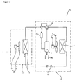
- FIG. 2 is a block diagram showing the motor controller of the air conditioner in accordance with an embodiment of the present invention.
- the motor controller 200 of the air conditioner in accordance with an embodiment of the present invention includes an inverter 220, a microcomputer 230, a power calculation unit 260, and an angle calculation unit 270.
- the motor controller 200 of the air conditioner in accordance with an embodiment of the present invention 200 may further include output current detection means E and output voltage detection means F.
- the motor controller 200 may further include a converter 210, a reactor L, a smoothing capacitor C, and so on.
- the reactor L is disposed between commercial AC power and the converter 210 and performs power factor correction or a boosting operation.
- the reactor L can also function to limit the harmonic current through high-speed switching of the converter 210.
- the converter 210 converts the commercial AC power, passing through the reactor L, into DC power and outputs converted DC power.
- the commercial AC power has been illustrated as single-phase AC power, it may be three-phase AC power.
- An internal configuration of the converter 210 may vary depending on the type of commercial AC power. For example, in the case of single-phase AC power, a half-bridge type converter having two switching elements and four diodes connected may be used. In the case of three-phase AC power, six switching elements and six diodes may be used.
- the converter 210 includes a plurality of switching elements and performs a boosting operation, power factor improvements and DC power conversion through the switching operation.
- the smoothing capacitor C is connected to the output terminal of the converter 210 and functions to smooth converted DC power output from the converter 210.
- the output terminal of the converter 210 is hereinafter referred to as a dc terminal or a dc link terminal.
- the DC voltage smoothed at the dc terminal is applied to the inverter 220.
- the inverter 220 includes a plurality of inverter switching elements.
- the inverter 220 converts the smoothed DC power into commercial AC power having a specific frequency through the on/off operations of the switching elements and outputs the converted AC power. More specifically, an upper arm switching element and a lower arm switching element, which are connected in series, forms one pair. A total of three pairs of the upper and lower arm switching elements are connected in parallel.
- the three-phase AC power output from the inverter 220 is applied to each phase of a three-phase motor 250.
- the three-phase motor 250 is equipped with a stator and a rotor. Each phase AC power having a specific frequency is applied to the coils of the stator of each phase, so that the rotor is rotated.
- Types of the three-phase motor 250 can be various such as an induction motor, a BLDC (Brushless DC) motor, and a synRM (Synchronous Reluctance) motor.
- the output current detection means E detects an output current i o flowing through the motor 250.
- the output current detection means E may be located in at least one phase between the inverter 220 and the motor 250.
- the output current detection means E may employ a current sensor, a current transformer (CT), a shunt resistor or the like for current detection. Further, the output current detection means E may be a shunt resistor having one terminal connected to at least one of the three lower arm switching elements of the inverter 220.
- the detected output current i o is input to the microcomputer 230 and the power calculation unit 260.
- the output voltage detection means F detects an output voltage v o applied to the motor 250.
- the output voltage detection means F may be located in at least one phase between the inverter 220 and the motor 250.
- a voltage sensor, a resistor element or the like may be used as the output voltage detection means F for voltage detection.
- the detected output voltage v o is input to the power calculation unit 260 for power calculation.
- the power calculation unit 260 calculates output power Pc based on the output current i o from the output current detection means E and the output voltage v o from the output voltage detection means F.
- the power calculation unit 260 can calculate the output power Pc of each phase of the three-phase motor.
- the power calculation unit 260 can also calculate output power Pc in real-time.
- the calculated output power Pc is applied to the angle calculation unit 270.
- the angle calculation unit 270 calculates an optimal phase angle ⁇ c of a current command value based on the calculated power Pc.
- the optimal phase angle ⁇ c of the current command value may be a phase angle when the amount of the calculated power Pc is a minimum. That is, the optimal phase angle ⁇ c of the current command value can be decided at the inflection point of calculated power.
- calculated power of each phase of the motor 250 can be axially transformed into d,q axes, that is, rotating reference frames.
- the optimal phase angle ⁇ c of the current command value can be decided based on power axially transformed into the d,q axes.
- the optimal phase angle ⁇ c of the current command value is simply decided based on the electric power Pc calculated in real-time, as described above.
- the calculated optimal phase angle ⁇ c is input to the microcomputer 230 and used to generate a switching control signal Sic.
- the microcomputer 230 may output the switching control signal Sic in order to control the inverter 220.
- the switching control signal Sic is a switching control signal for PWM and is generated based on the output current i o , detected in the output current detection means E, and the calculated optimal phase angle ⁇ c.
- microcomputer 230 A detailed operation of the microcomputer 230 will be described later on with reference to FIG. 3 .
- the motor controller 200 of the air conditioner in accordance with an embodiment of the present invention may further include dc terminal voltage detection means for detecting a dc terminal voltage across the smoothing capacitor C.
- the detected dc terminal voltages may be used to generate a converter switching control signal to control the switching operation of the converter.
- the converter switching control signal can be generated in the same microcomputer as that of the microcomputer 230,-but may also be generated in a different microcomputer from that of the same microcomputer.
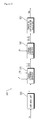
- FIG. 3 is an internal block diagram of a microcomputer of FIG. 2 .
- the microcomputer 230 includes an estimation unit 305, a current command generator 310, a voltage command generator 320, and a switching control signal output unit 330.
- the estimation unit 305 estimates a rotor velocity v of the motor based on the detected output current i o .
- the estimation unit 305 estimates the rotor velocity v using a velocity estimation algorithm. Meanwhile, the estimation unit 305 can estimate a position of the motor (250) rotor. In the case in which the position of the motor rotor is estimated, the rotor velocity can be calculated using a rotor position since the rotor position has a differential relationship with the velocity v.
- the current command generator 310 generates d,q-axis current command values i * d , i * q based on the estimated velocity v, a velocity command value v*, and the optimal phase angle ⁇ c.
- the current command generator 310 can decide an amount I * of the current command values based on the estimated velocity v and the velocity command value v* and can generate the d,q-axis current command values i * d , i * q by employing the calculated optimal phase angle ⁇ c. That is, the amount I * of the current command values, the optimal phase angle ⁇ c, and the d,q-axis current command values i * d , i * q have the following Equation 1 relationship.
- i * d I * ⁇ cos ⁇ c
- i * q I * ⁇ sin ⁇ c
- the current command generator 310 can include a PI controller (not shown) for generating the d,q-axis current command values i * d , i * q , and a d,q-axis current command limit unit (not shown) for limiting the levels of the d,q-axis current command values i * d , i * q so that the d,q-axis current command values i * d , i * q do not exceed specific values.
- a PI controller not shown
- a d,q-axis current command limit unit not shown
- the voltage command generator 320 generates d,q-axis voltage command values v * d , v * q based on the d,q-axis current command values i * d , i * q and a detected output current i o . That is, the voltage command generator 320 can include a PI controller (not shown) for generating the d,q-axis voltage command values v * d ,v * q , and a d,q-axis voltage command limit unit (not shown) for limiting the levels of the d,q-axis voltage command values v * d ,v * q so that the d,q-axis voltage command values v * d ,v * q do not exceed specific values.
- a PI controller not shown
- a d,q-axis voltage command limit unit not shown
- the switching control signal output unit 330 outputs the switching control signal Sic based on the d,q-axis voltage command values v * d , v * q in order to drive the inverter switching elements.
- the switching control signal Sic is applied to the gate terminal of the inverter (220) switching elements and controls on/off of the inverter switching elements.
- the output current i o is input to the voltage command generator 320, but the present invention is not limited thereto.
- the output current i o may be a value transformed into rotating reference frames of the d,q axes.
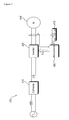
- FIG. 4 is a block diagram showing a motor controller of an air conditioner in accordance with a second embodiment of the present invention.
- the motor controller 400 of the air conditioner in accordance with an embodiment of the present invention includes an inverter 420, a microcomputer 430, and an angle calculation unit 470.
- the motor controller 400 of the air conditioner in accordance with an embodiment of the present invention further includes output current detection means E.
- the motor controller 400 of the air conditioner in accordance with an embodiment of the present invention may further include a converter 410, a reactor L, a smoothing capacitor C, and so on.
- the motor controller 400 of the air conditioner of FIG. 4 is similar to the motor controller 200 of the air conditioner of FIG. 2 . That is, the reactor L, the converter 410, the inverter 420, the microcomputer 430, and the smoothing capacitor C have the same operations as those of FIG. 2 . Hereinafter, description is given on the basis of a difference between the motor controller 400 of FIG. 4 and the motor controller 200 of FIG. 2 .
- the output current detection means E detects an output current i o flowing through a motor 450. Description on the output current detection means E is almost identical to that of FIG. 2 . However, the detected output current i o is input to the microcomputer 430 and the angle calculation unit 470.
- the angle calculation unit 470 calculates an optimal phase angle ⁇ c of a current command value based on the output current i o .
- the optimal phase angle ⁇ c of the current command value may be a phase angle when an amount of the output current i o is a minimum. That is, the optimal phase angle ⁇ c of the current command value may be decided at the inflection point of the output current i o .
- an output current of each phase of the motor 450 can be axially transformed into d,q axes, that is, rotating reference frames.
- the optimal phase angle ⁇ c of a current command value can be decided based on the output current axially transformed into the d,q axes.
- the optimal phase angle ⁇ c of the current command value is simply decided based on the output current i o calculated in real-time, as described above. Meanwhile, the calculated optimal phase angle ⁇ c is input to the microcomputer 430 and used to generate a switching control signal Sic.
- the motor controller of the air conditioner in accordance with the present invention can be employed to simply decide an optimal phase angle of a current command value in real-time.
Landscapes
- Engineering & Computer Science (AREA)
- Mechanical Engineering (AREA)
- General Engineering & Computer Science (AREA)
- Chemical & Material Sciences (AREA)
- Combustion & Propulsion (AREA)
- Physics & Mathematics (AREA)
- Mathematical Physics (AREA)
- Power Engineering (AREA)
- Fuzzy Systems (AREA)
- Signal Processing (AREA)
- Thermal Sciences (AREA)
- Control Of Ac Motors In General (AREA)
- Inverter Devices (AREA)
- Air Conditioning Control Device (AREA)
Abstract
Description
- The present invention relates to a motor controller of an air conditioner, and more specifically to a motor controller of an air conditioner which can decide an optimal phase angle of a current command value simply in real-time.
- An air conditioner is an apparatus disposed in space, such as rooms, dining rooms, office rooms, and shops, and adapted to control temperature, moisture, cleaning and air stream of the air in order to maintain pleasant indoor environments.
- An air conditioner is generally divided into a unit type and a separate type. The unit type and the separate type are identical in terms of their functions. The unit type includes an integrated cooling and heat-dissipation function and is installed in a wall of a house or hung on a wall. In the separate type, an indoor unit having the cooling/heating functions is installed indoors and an outdoor unit having the heat-dissipation and compression functions is installed outdoors and thereafter both the units are connected by refrigerant ducts.
- Meanwhile, the air conditioner uses motors in a compressor, fans, and so on and includes a motor controller for driving them. The motor controller of the air conditioner converts input commercial AC power into DC power, converts the DC power into commercial AC power having a specific frequency, and supplies the AC power to the motors in order to control the motors for the compressor, fans, and so on.
- To control this air conditioner, a switching control signal to drive an inverter is applied to the air conditioner. A variety of schemes for enabling the phase angle of a current command value to have an optimal value when the switching control signal is generated have been discussed.
- An object of the present invention is to provide a motor controller of an air conditioner, which can decide an optimal phase angle of a current command value simply in real-time.
- There is provided a motor controller for an air conditioner, the motor controller comprising: an inverter adapted to convert a DC voltage into an AC voltage and supply the AC voltage to a motor; an angle calculation unit arranged to calculate a phase angle of a current command value based on the electric power supplied to the motor, the current supplied to the motor, or the voltage supplied to the motor; and a microcomputer arranged to output a control signal to control the inverter based on said calculated phase angle.
- The motor controller may also include a power calculation unit arranged to calculate electric power applied to the motor.
- By the term current command value, we mean a command signal which results in the output power of the motor reaching the desired value, i.e. a minimum value. The calculation of optimum phase angle takes place continuously in real-time to provide a continuously optimised/minimised power output of the motor.
- In some embodiments, the phase angle of the current supplied to the motor may be calculated using a frame of reference rotating with the motor. In this case the rotating frame may be transformed into d,q axes such that real and imaginary or complex parts of the current may be calculated.
- In some embodiments the optimisation of phase angle will have a different optimum value depending on if the phase angle is optimised with respect to power or current. In other embodiments, the phase angle will have the same optimum.
- A motor controller of an air conditioner according to an exemplary embodiment of the present invention includes an inverter including a plurality of switching elements and adapted to convert a DC voltage, input through switching operations of the switching elements, into an AC voltage and supply the converted voltage to a motor, a power calculation unit that calculates electric power applied to the motor, an angle calculation unit that calculates an optimal phase angle of a current command value based on the calculated electric power; and a microcomputer that outputs an inverter switching control signal to control the switching elements of the inverter based on the optimal phase angle.
- A motor controller of an air conditioner according to an exemplary embodiment of the present invention includes an inverter including a plurality of switching elements and adapted to convert a DC voltage, input through switching operations of the switching elements, into an AC voltage and supply the converted voltage to a motor, an angle calculation unit that calculates an optimal phase angle of a current command value based on an output current flowing through the motor, and a microcomputer that outputs an inverter switching control signal to control the switching elements of the inverter based on the optimal phase angle.
- A motor controller of an air conditioner in accordance with an embodiment of the present invention can decide an optimal phase angle of a current command value simply. Further, an optimal phase angle of a current command value can be decided in real-time.
-
-
FIG. 1 is a schematic view of an air conditioner pertinent the present invention; -
FIG. 2 is a block diagram showing a motor controller of an air conditioner in accordance with a second embodiment of the present invention; -
FIG. 3 is an internal block diagram of a microcomputer ofFIG. 2 ; and -
FIG. 4 is a block diagram showing a motor controller of an air conditioner in accordance with an embodiment of the present invention. - Hereafter, embodiments of the present invention will be described in detail with reference to the accompanying drawings.
-
FIG. 1 is a schematic view of an air conditioner pertinent to the present invention. - Referring to the drawing, an
air conditioner 50 is largely divided into an indoor unit I and an outdoor unit O. - The outdoor unit O includes a
compressor 2 functioning to compress refrigerant, amotor 2b for the compressor for driving the compressor, an outdoor-side heat exchanger 4 functioning to dissipate heat of compressed refrigerant, anoutdoor ventilation fan 5, including anoutdoor fan 5a disposed on one side of theoutdoor heat exchanger 5 and configured to accelerate heat dissipation of refrigerant and amotor 5b for rotating theoutdoor fan 5a, anexpansion mechanism 6 for expanding condensed refrigerant, a cooling/heating switching valve 10 for switching the flow passage of compressed refrigerant, an accumulator 3 for temporarily storing vaporized refrigerant, removing moisture and alien substance from the refrigerant and supplying refrigerant of a specific pressure to the compressor, and so on. - The indoor unit I includes an indoor-side heat exchanger 8 disposed indoor and performing a cooling/heating function, an indoor ventilation fan 9 disposed on one side of the indoor-side heat exchanger 8 and including an
indoor fan 9a for accelerating heat dissipation of refrigerant and amotor 9b for rotating theindoor fan 9a, and so on. - At least one indoor-side heat exchanger 8 can be installed. The
compressor 2 can employ at least one of an inverter compressor and a constant speed compressor. Further, theair conditioner 50 can be constructed as a cooling device for cooling the indoor or a heat pump for cooling or heating the indoor. - Meanwhile, the motor in the motor controller of the air conditioner in accordance with an embodiment of the present invention can be each of
motor -
FIG. 2 is a block diagram showing the motor controller of the air conditioner in accordance with an embodiment of the present invention. - Referring to the drawing, the
motor controller 200 of the air conditioner in accordance with an embodiment of the present invention includes aninverter 220, amicrocomputer 230, apower calculation unit 260, and anangle calculation unit 270. Themotor controller 200 of the air conditioner in accordance with an embodiment of thepresent invention 200 may further include output current detection means E and output voltage detection means F. Themotor controller 200 may further include aconverter 210, a reactor L, a smoothing capacitor C, and so on. - The reactor L is disposed between commercial AC power and the
converter 210 and performs power factor correction or a boosting operation. The reactor L can also function to limit the harmonic current through high-speed switching of theconverter 210. - The
converter 210 converts the commercial AC power, passing through the reactor L, into DC power and outputs converted DC power. Although, in the drawing, the commercial AC power has been illustrated as single-phase AC power, it may be three-phase AC power. An internal configuration of theconverter 210 may vary depending on the type of commercial AC power. For example, in the case of single-phase AC power, a half-bridge type converter having two switching elements and four diodes connected may be used. In the case of three-phase AC power, six switching elements and six diodes may be used. Theconverter 210 includes a plurality of switching elements and performs a boosting operation, power factor improvements and DC power conversion through the switching operation. - The smoothing capacitor C is connected to the output terminal of the
converter 210 and functions to smooth converted DC power output from theconverter 210. The output terminal of theconverter 210 is hereinafter referred to as a dc terminal or a dc link terminal. The DC voltage smoothed at the dc terminal is applied to theinverter 220. - The
inverter 220 includes a plurality of inverter switching elements. Theinverter 220 converts the smoothed DC power into commercial AC power having a specific frequency through the on/off operations of the switching elements and outputs the converted AC power. More specifically, an upper arm switching element and a lower arm switching element, which are connected in series, forms one pair. A total of three pairs of the upper and lower arm switching elements are connected in parallel. The three-phase AC power output from theinverter 220 is applied to each phase of a three-phase motor 250. - Here, the three-
phase motor 250 is equipped with a stator and a rotor. Each phase AC power having a specific frequency is applied to the coils of the stator of each phase, so that the rotor is rotated. Types of the three-phase motor 250 can be various such as an induction motor, a BLDC (Brushless DC) motor, and a synRM (Synchronous Reluctance) motor. - The output current detection means E detects an output current io flowing through the
motor 250. The output current detection means E may be located in at least one phase between theinverter 220 and themotor 250. The output current detection means E may employ a current sensor, a current transformer (CT), a shunt resistor or the like for current detection. Further, the output current detection means E may be a shunt resistor having one terminal connected to at least one of the three lower arm switching elements of theinverter 220. The detected output current io is input to themicrocomputer 230 and thepower calculation unit 260. - The output voltage detection means F detects an output voltage vo applied to the
motor 250. The output voltage detection means F may be located in at least one phase between theinverter 220 and themotor 250. A voltage sensor, a resistor element or the like may be used as the output voltage detection means F for voltage detection. The detected output voltage vo is input to thepower calculation unit 260 for power calculation. - The
power calculation unit 260 calculates output power Pc based on the output current io from the output current detection means E and the output voltage vo from the output voltage detection means F. Thepower calculation unit 260 can calculate the output power Pc of each phase of the three-phase motor. Thepower calculation unit 260 can also calculate output power Pc in real-time. The calculated output power Pc is applied to theangle calculation unit 270. - The
angle calculation unit 270 calculates an optimal phase angle θc of a current command value based on the calculated power Pc. The optimal phase angle θc of the current command value may be a phase angle when the amount of the calculated power Pc is a minimum. That is, the optimal phase angle θc of the current command value can be decided at the inflection point of calculated power. - Meanwhile, calculated power of each phase of the
motor 250 can be axially transformed into d,q axes, that is, rotating reference frames. The optimal phase angle θc of the current command value can be decided based on power axially transformed into the d,q axes. The optimal phase angle θc of the current command value is simply decided based on the electric power Pc calculated in real-time, as described above. Meanwhile, the calculated optimal phase angle θc is input to themicrocomputer 230 and used to generate a switching control signal Sic. - The
microcomputer 230 may output the switching control signal Sic in order to control theinverter 220. The switching control signal Sic is a switching control signal for PWM and is generated based on the output current io, detected in the output current detection means E, and the calculated optimal phase angle θc. - A detailed operation of the
microcomputer 230 will be described later on with reference toFIG. 3 . - Meanwhile, the
motor controller 200 of the air conditioner in accordance with an embodiment of the present invention may further include dc terminal voltage detection means for detecting a dc terminal voltage across the smoothing capacitor C. The detected dc terminal voltages may be used to generate a converter switching control signal to control the switching operation of the converter. Here, the converter switching control signal can be generated in the same microcomputer as that of themicrocomputer 230,-but may also be generated in a different microcomputer from that of the same microcomputer. -
FIG. 3 is an internal block diagram of a microcomputer ofFIG. 2 . - Referring to the drawing, the
microcomputer 230 includes anestimation unit 305, acurrent command generator 310, avoltage command generator 320, and a switching controlsignal output unit 330. - The
estimation unit 305 estimates a rotor velocity v of the motor based on the detected output current io. Theestimation unit 305 estimates the rotor velocity v using a velocity estimation algorithm. Meanwhile, theestimation unit 305 can estimate a position of the motor (250) rotor. In the case in which the position of the motor rotor is estimated, the rotor velocity can be calculated using a rotor position since the rotor position has a differential relationship with the velocity v. - The
current command generator 310 generates d,q-axis current command values i* d, i* q based on the estimated velocity v, a velocity command value v*, and the optimal phase angle θc. Thecurrent command generator 310 can decide an amount I* of the current command values based on the estimated velocity v and the velocity command value v* and can generate the d,q-axis current command values i* d, i* q by employing the calculated optimal phase angle θc. That is, the amount I* of the current command values, the optimal phase angle θc, and the d,q-axis current command values i* d, i* q have the following Equation 1 relationship.
- That is, the
current command generator 310 can include a PI controller (not shown) for generating the d,q-axis current command values i* d, i* q, and a d,q-axis current command limit unit (not shown) for limiting the levels of the d,q-axis current command values i* d, i* q so that the d,q-axis current command values i* d, i* q do not exceed specific values. - The
voltage command generator 320 generates d,q-axis voltage command values v* d, v* q based on the d,q-axis current command values i* d, i* q and a detected output current io. That is, thevoltage command generator 320 can include a PI controller (not shown) for generating the d,q-axis voltage command values v* d,v* q, and a d,q-axis voltage command limit unit (not shown) for limiting the levels of the d,q-axis voltage command values v* d,v* q so that the d,q-axis voltage command values v* d,v* q do not exceed specific values. - The switching control
signal output unit 330 outputs the switching control signal Sic based on the d,q-axis voltage command values v* d, v* q in order to drive the inverter switching elements. The switching control signal Sic is applied to the gate terminal of the inverter (220) switching elements and controls on/off of the inverter switching elements. - Meanwhile, it has been shown in the drawing that the output current io is input to the
voltage command generator 320, but the present invention is not limited thereto. The output current io may be a value transformed into rotating reference frames of the d,q axes. -
FIG. 4 is a block diagram showing a motor controller of an air conditioner in accordance with a second embodiment of the present invention. - Referring to the drawing, the
motor controller 400 of the air conditioner in accordance with an embodiment of the present invention includes aninverter 420, amicrocomputer 430, and anangle calculation unit 470. Themotor controller 400 of the air conditioner in accordance with an embodiment of the present invention further includes output current detection means E. Themotor controller 400 of the air conditioner in accordance with an embodiment of the present invention may further include aconverter 410, a reactor L, a smoothing capacitor C, and so on. - The
motor controller 400 of the air conditioner ofFIG. 4 is similar to themotor controller 200 of the air conditioner ofFIG. 2 . That is, the reactor L, theconverter 410, theinverter 420, themicrocomputer 430, and the smoothing capacitor C have the same operations as those ofFIG. 2 . Hereinafter, description is given on the basis of a difference between themotor controller 400 ofFIG. 4 and themotor controller 200 ofFIG. 2 . - The output current detection means E detects an output current io flowing through a
motor 450. Description on the output current detection means E is almost identical to that ofFIG. 2 . However, the detected output current io is input to themicrocomputer 430 and theangle calculation unit 470. - The
angle calculation unit 470 calculates an optimal phase angle θc of a current command value based on the output current io. The optimal phase angle θc of the current command value may be a phase angle when an amount of the output current io is a minimum. That is, the optimal phase angle θc of the current command value may be decided at the inflection point of the output current io. - Meanwhile, an output current of each phase of the
motor 450 can be axially transformed into d,q axes, that is, rotating reference frames. The optimal phase angle θc of a current command value can be decided based on the output current axially transformed into the d,q axes. The optimal phase angle θc of the current command value is simply decided based on the output current io calculated in real-time, as described above. Meanwhile, the calculated optimal phase angle θc is input to themicrocomputer 430 and used to generate a switching control signal Sic. - While the invention has been described in connection with the embodiments with reference to the accompanying drawings, it will be understood that those skilled in the art can implement the technical constructions of the present invention in various forms without departing from the technical spirit or indispensable characteristics of the present invention. Therefore, the above-described embodiments should be construed to be illustrative. Furthermore, the scope of the present invention is defined by the appended claims rather than the above detailed description. Thus, the present invention should be construed to cover all modifications or variations induced from the meaning and range of the appended claims and their equivalents.
- The motor controller of the air conditioner in accordance with the present invention can be employed to simply decide an optimal phase angle of a current command value in real-time.
Claims (11)
- A motor controller (200) of an air conditioner, comprising:an inverter (220) including a plurality of switching elements and adapted to convert a DC voltage, received by the inverter through switching operations of the switching elements, into an AC voltage and supply the converted voltage to a motor (250);a power calculation unit (260) arranged to calculate electric power applied to the motor (250);an angle calculation unit (270) arranged to calculate a phase angle of a current command value based on the calculated electric power; anda microcomputer (230) arranged to output an inverter switching control signal (Sic) to control the switching elements of the inverter (220) based on the calculated phase angle.
- The motor controller (200) of the air conditioner according to claim 1, wherein the calculated phase angle is the phase angle when an amount of the calculated electric power is a minimum.
- The motor controller (200) of the air conditioner according to claim 1 or claim 2, further comprising:output current detection means (E) for detecting current flowing through the motor (200); andoutput voltage detection means (F) for detecting a voltage applied to the motor (200),wherein the power calculation unit (260) calculates the power applied to the motor based on the output current and the output voltage.
- The motor controller of the air conditioner according to any preceding claim, wherein the microcomputer (230) comprises:an estimation (305) unit that estimates a velocity based on output current flowing through the motor (250);a current command generator (310) that generates d,q-axis current command values based on the estimated velocity, a velocity command value, and the calculated phase angle;a voltage command generator (320) that generates d,q-axis voltage command values based on the d,q-axis current command values and the output current; anda switching control signal output unit (330) that outputs the inverter switching control signal (Sic) based on the d,q-axis voltage command values.
- A motor controller (400) of an air conditioner, comprising:an inverter (420) including a plurality of switching elements and adapted to convert a DC voltage, received by the inverter through switching operations of the switching elements, into an AC voltage and supply the converted voltage to a motor 450);an angle calculation unit (470) arranged to calculate a phase angle of a current command value based on an output current flowing through the motor (450); anda microcomputer (430) arranged to output an inverter switching control signal (Sic) to control the switching elements of the inverter based on the calculated phase angle.
- The motor controller (400) of the air conditioner according to claim 5, wherein the calculated phase angle is the phase angle when an amount of the output current is a minimum.
- The motor controller (400) of the air conditioner according to claim 5 or claim 6, further comprising output current detection means (E) for detecting an output current flowing through the motor (450).
- The motor controller (400) of the air conditioner according to any preceding claim, wherein the microcomputer (430) comprises:an estimation unit (305) that estimates a velocity based on the output current to the motor;a current command generator (310) that generates d,q-axis current command values based on the estimated velocity, a velocity command value, and the calculated phase angle;a voltage command generator (320) that generates d,q-axis voltage command values based on the d,q-axis current command values and the output current; anda switching control signal output unit (330) that outputs the inverter switching control signal based on the d,q-axis voltage command values.
- An air conditioner comprising the motor controller of any preceding claim.
- A method of controlling a motor (200) of an air conditioner, comprising:receiving a DC voltage, converting it to an AC voltage using an inverter and supplying the AC voltage to the motor;calculating the electric power applied to the motor;calculating a phase angle of a current command value based on the calculated electric power; andoutputting to the inverter a control signal to control the inverter based on the calculated phase angle.
- A method of controlling a motor (400) of an air conditioner, comprising:receiving a DC voltage, converting it to an AC voltage using an inverter and supplying the AC voltage to the motor,calculating a phase angle of a current command value based on an output current flowing through the motor; andoutputting to the inverter a control signal to control the inverter based on the calculated phase angle.
Applications Claiming Priority (1)
| Application Number | Priority Date | Filing Date | Title |
|---|---|---|---|
| KR1020070118734A KR101395891B1 (en) | 2007-11-20 | 2007-11-20 | Motor controller of air conditioner |
Publications (2)
| Publication Number | Publication Date |
|---|---|
| EP2063194A1 true EP2063194A1 (en) | 2009-05-27 |
| EP2063194B1 EP2063194B1 (en) | 2015-11-11 |
Family
ID=40351694
Family Applications (1)
| Application Number | Title | Priority Date | Filing Date |
|---|---|---|---|
| EP08253750.7A Not-in-force EP2063194B1 (en) | 2007-11-20 | 2008-11-18 | Motor controller of air conditioner |
Country Status (5)
| Country | Link |
|---|---|
| US (1) | US8120299B2 (en) |
| EP (1) | EP2063194B1 (en) |
| KR (1) | KR101395891B1 (en) |
| ES (1) | ES2553555T3 (en) |
| WO (1) | WO2009066839A2 (en) |
Families Citing this family (12)
| Publication number | Priority date | Publication date | Assignee | Title |
|---|---|---|---|---|
| US8698433B2 (en) * | 2009-08-10 | 2014-04-15 | Emerson Climate Technologies, Inc. | Controller and method for minimizing phase advance current |
| US8860342B2 (en) | 2011-09-15 | 2014-10-14 | Curtiss-Wright Electro-Mechanical Corporation | System and method for controlling a permanent magnet motor |
| JP6428248B2 (en) * | 2014-12-22 | 2018-11-28 | 株式会社デンソー | Motor control device |
| US10312798B2 (en) | 2016-04-15 | 2019-06-04 | Emerson Electric Co. | Power factor correction circuits and methods including partial power factor correction operation for boost and buck power converters |
| US10284132B2 (en) | 2016-04-15 | 2019-05-07 | Emerson Climate Technologies, Inc. | Driver for high-frequency switching voltage converters |
| US10763740B2 (en) | 2016-04-15 | 2020-09-01 | Emerson Climate Technologies, Inc. | Switch off time control systems and methods |
| US10656026B2 (en) | 2016-04-15 | 2020-05-19 | Emerson Climate Technologies, Inc. | Temperature sensing circuit for transmitting data across isolation barrier |
| US10305373B2 (en) | 2016-04-15 | 2019-05-28 | Emerson Climate Technologies, Inc. | Input reference signal generation systems and methods |
| US9933842B2 (en) | 2016-04-15 | 2018-04-03 | Emerson Climate Technologies, Inc. | Microcontroller architecture for power factor correction converter |
| US10277115B2 (en) | 2016-04-15 | 2019-04-30 | Emerson Climate Technologies, Inc. | Filtering systems and methods for voltage control |
| KR102017150B1 (en) * | 2018-04-17 | 2019-09-02 | 엘지전자 주식회사 | Compressor driving apparatus and air conditioner including the same |
| CN108488948B (en) * | 2018-06-05 | 2023-11-14 | 珠海格力电器股份有限公司 | Air conditioner, air conditioner control system and outdoor unit switch circuit |
Citations (4)
| Publication number | Priority date | Publication date | Assignee | Title |
|---|---|---|---|---|
| US4816985A (en) * | 1987-02-19 | 1989-03-28 | Mitsubishi Denki Kabushiki Kaisha | Apparatus for controlling an alternating current power supply |
| JP2003259680A (en) * | 2002-02-28 | 2003-09-12 | Mitsubishi Electric Corp | Synchronous motor driving apparatus, inverter apparatus and control method of synchronous motor |
| JP2004096915A (en) * | 2002-09-02 | 2004-03-25 | Mitsubishi Electric Corp | Method and apparatus for controlling synchronous motor |
| JP2006320127A (en) * | 2005-05-13 | 2006-11-24 | Denso Corp | Controller for inverter |
Family Cites Families (16)
| Publication number | Priority date | Publication date | Assignee | Title |
|---|---|---|---|---|
| US3840799A (en) * | 1973-09-11 | 1974-10-08 | Westinghouse Electric Corp | Commutatorless dc motor drive arrangement |
| JPS59106882A (en) * | 1982-12-10 | 1984-06-20 | Mitsubishi Electric Corp | Protecting device for air conditioner with inverter |
| US5272429A (en) * | 1990-10-01 | 1993-12-21 | Wisconsin Alumni Research Foundation | Air gap flux measurement using stator third harmonic voltage and uses |
| JPH0544980A (en) * | 1991-08-09 | 1993-02-23 | Hitachi Ltd | Controlling method for air conditioner |
| JPH0835712A (en) * | 1994-07-26 | 1996-02-06 | Fujitsu General Ltd | Controller for air conditioner |
| DE69533001T2 (en) * | 1995-10-06 | 2005-05-04 | Hitachi, Ltd. | MOTOR CONTROLLER |
| JP3328830B2 (en) * | 1996-11-20 | 2002-09-30 | 三菱電機株式会社 | Air conditioner inverter control device |
| TW364049B (en) * | 1997-09-24 | 1999-07-11 | Toshiba Corp | Power conversion apparatus and air conditioner using the same |
| US5994869A (en) * | 1997-12-05 | 1999-11-30 | General Electric Company | Power conversion circuit for a motor |
| US20020024828A1 (en) * | 2000-08-31 | 2002-02-28 | Hidetake Hayashi | Inverter suitable for use with portable AC power supply unit |
| JP4693214B2 (en) * | 2000-08-31 | 2011-06-01 | 東芝コンシューマエレクトロニクス・ホールディングス株式会社 | Inverter device |
| JP2005151635A (en) * | 2003-11-12 | 2005-06-09 | Mitsubishi Electric Corp | Motor driving unit, blower, freezing air-conditioner, and method of driving motor |
| US7250742B2 (en) * | 2004-11-08 | 2007-07-31 | International Rectifier Corporation | Digital control of bridgeless power factor correction circuit |
| JP4664699B2 (en) * | 2005-02-10 | 2011-04-06 | 株式会社東芝 | Parallel operation controller for power converter |
| KR20070067313A (en) * | 2005-12-23 | 2007-06-28 | 엘지전자 주식회사 | Compressor driver of an air conditioner |
| KR100764779B1 (en) * | 2006-03-14 | 2007-10-11 | 엘지전자 주식회사 | Apparatus for supplying dc power source |
-
2007
- 2007-11-20 KR KR1020070118734A patent/KR101395891B1/en active IP Right Grant
-
2008
- 2008-04-30 WO PCT/KR2008/002442 patent/WO2009066839A2/en active Application Filing
- 2008-11-18 ES ES08253750.7T patent/ES2553555T3/en active Active
- 2008-11-18 EP EP08253750.7A patent/EP2063194B1/en not_active Not-in-force
- 2008-11-19 US US12/292,479 patent/US8120299B2/en not_active Expired - Fee Related
Patent Citations (4)
| Publication number | Priority date | Publication date | Assignee | Title |
|---|---|---|---|---|
| US4816985A (en) * | 1987-02-19 | 1989-03-28 | Mitsubishi Denki Kabushiki Kaisha | Apparatus for controlling an alternating current power supply |
| JP2003259680A (en) * | 2002-02-28 | 2003-09-12 | Mitsubishi Electric Corp | Synchronous motor driving apparatus, inverter apparatus and control method of synchronous motor |
| JP2004096915A (en) * | 2002-09-02 | 2004-03-25 | Mitsubishi Electric Corp | Method and apparatus for controlling synchronous motor |
| JP2006320127A (en) * | 2005-05-13 | 2006-11-24 | Denso Corp | Controller for inverter |
Also Published As
| Publication number | Publication date |
|---|---|
| KR20090052168A (en) | 2009-05-25 |
| EP2063194B1 (en) | 2015-11-11 |
| WO2009066839A3 (en) | 2011-06-30 |
| ES2553555T3 (en) | 2015-12-10 |
| US20090146591A1 (en) | 2009-06-11 |
| US8120299B2 (en) | 2012-02-21 |
| KR101395891B1 (en) | 2014-05-15 |
| WO2009066839A2 (en) | 2009-05-28 |
Similar Documents
| Publication | Publication Date | Title |
|---|---|---|
| EP2063194B1 (en) | Motor controller of air conditioner | |
| US8169180B2 (en) | Motor controller of air conditioner | |
| EP2073373A2 (en) | Method for controlling motor of air conditioner | |
| KR101694539B1 (en) | Apparatus for dirving compressor of an air conditioner and method for driving the same | |
| KR102203433B1 (en) | Motor driving device and air conditioner including the same | |
| WO2009064050A2 (en) | Motor controller of air conditioner | |
| KR100940097B1 (en) | Motor controller of air conditioner | |
| KR101054438B1 (en) | Electric motor drive of air conditioner | |
| KR101054439B1 (en) | Electric motor drive of air conditioner | |
| KR101591326B1 (en) | Motor driver of air conditioner | |
| KR20100003580A (en) | Motor controller of air conditioner | |
| JP5136568B2 (en) | Electric motor control circuit and air conditioner using the control circuit | |
| KR102010388B1 (en) | Power converting apparatus and air conditioner including the same | |
| KR20090081914A (en) | Motor controller of air conditioner | |
| KR20090049854A (en) | Motor controller of air conditioner | |
| KR102017150B1 (en) | Compressor driving apparatus and air conditioner including the same | |
| KR100956435B1 (en) | Motor controller of air conditioner | |
| KR100925276B1 (en) | Motor controller and method for controlling the same | |
| KR20100003579A (en) | Motor controller of air conditioner and method for controlling the same | |
| KR101687549B1 (en) | Apparatus for dirving motor of air conditioner and method for driving the same | |
| KR20090041596A (en) | Motor controller of air conditioner | |
| KR20090052165A (en) | Motor controller of air conditioner | |
| KR20110015242A (en) | Apparatus for dirving motor of air conditioner and method for driving the same | |
| KR20100036781A (en) | Motor controller | |
| KR20090036418A (en) | Motor controller of air conditioner |
Legal Events
| Date | Code | Title | Description |
|---|---|---|---|
| PUAI | Public reference made under article 153(3) epc to a published international application that has entered the european phase |
Free format text: ORIGINAL CODE: 0009012 |
|
| AK | Designated contracting states |
Kind code of ref document: A1 Designated state(s): AT BE BG CH CY CZ DE DK EE ES FI FR GB GR HR HU IE IS IT LI LT LU LV MC MT NL NO PL PT RO SE SI SK TR |
|
| AX | Request for extension of the european patent |
Extension state: AL BA MK RS |
|
| 17P | Request for examination filed |
Effective date: 20091124 |
|
| AKX | Designation fees paid |
Designated state(s): ES FR IT |
|
| REG | Reference to a national code |
Ref country code: DE Ref legal event code: 8566 |
|
| 17Q | First examination report despatched |
Effective date: 20140806 |
|
| GRAP | Despatch of communication of intention to grant a patent |
Free format text: ORIGINAL CODE: EPIDOSNIGR1 |
|
| INTG | Intention to grant announced |
Effective date: 20150519 |
|
| GRAS | Grant fee paid |
Free format text: ORIGINAL CODE: EPIDOSNIGR3 |
|
| GRAA | (expected) grant |
Free format text: ORIGINAL CODE: 0009210 |
|
| AK | Designated contracting states |
Kind code of ref document: B1 Designated state(s): ES FR IT |
|
| REG | Reference to a national code |
Ref country code: ES Ref legal event code: FG2A Ref document number: 2553555 Country of ref document: ES Kind code of ref document: T3 Effective date: 20151210 |
|
| PG25 | Lapsed in a contracting state [announced via postgrant information from national office to epo] |
Ref country code: IT Free format text: LAPSE BECAUSE OF FAILURE TO SUBMIT A TRANSLATION OF THE DESCRIPTION OR TO PAY THE FEE WITHIN THE PRESCRIBED TIME-LIMIT Effective date: 20151111 |
|
| PLBE | No opposition filed within time limit |
Free format text: ORIGINAL CODE: 0009261 |
|
| STAA | Information on the status of an ep patent application or granted ep patent |
Free format text: STATUS: NO OPPOSITION FILED WITHIN TIME LIMIT |
|
| 26N | No opposition filed |
Effective date: 20160812 |
|
| REG | Reference to a national code |
Ref country code: FR Ref legal event code: ST Effective date: 20161003 |
|
| PG25 | Lapsed in a contracting state [announced via postgrant information from national office to epo] |
Ref country code: FR Free format text: LAPSE BECAUSE OF NON-PAYMENT OF DUE FEES Effective date: 20160111 |
|
| PGFP | Annual fee paid to national office [announced via postgrant information from national office to epo] |
Ref country code: ES Payment date: 20191203 Year of fee payment: 12 |
|
| REG | Reference to a national code |
Ref country code: ES Ref legal event code: FD2A Effective date: 20220201 |
|
| PG25 | Lapsed in a contracting state [announced via postgrant information from national office to epo] |
Ref country code: ES Free format text: LAPSE BECAUSE OF NON-PAYMENT OF DUE FEES Effective date: 20201119 |