EP2062633B1 - Filter assembly with a filtering element - Google Patents
Filter assembly with a filtering element Download PDFInfo
- Publication number
- EP2062633B1 EP2062633B1 EP09100154A EP09100154A EP2062633B1 EP 2062633 B1 EP2062633 B1 EP 2062633B1 EP 09100154 A EP09100154 A EP 09100154A EP 09100154 A EP09100154 A EP 09100154A EP 2062633 B1 EP2062633 B1 EP 2062633B1
- Authority
- EP
- European Patent Office
- Prior art keywords
- filter
- housing
- housing cover
- filtering element
- screw connection
- Prior art date
- Legal status (The legal status is an assumption and is not a legal conclusion. Google has not performed a legal analysis and makes no representation as to the accuracy of the status listed.)
- Active
Links
- 238000001914 filtration Methods 0.000 title claims description 14
- 239000000446 fuel Substances 0.000 claims description 6
- XSQUKJJJFZCRTK-UHFFFAOYSA-N Urea Chemical compound NC(N)=O XSQUKJJJFZCRTK-UHFFFAOYSA-N 0.000 claims description 3
- 239000004202 carbamide Substances 0.000 claims description 3
- 238000002485 combustion reaction Methods 0.000 claims description 2
- 238000007789 sealing Methods 0.000 description 17
- 238000011161 development Methods 0.000 description 3
- 230000018109 developmental process Effects 0.000 description 3
- 238000010276 construction Methods 0.000 description 2
- 230000000694 effects Effects 0.000 description 2
- 239000012530 fluid Substances 0.000 description 2
- 238000009434 installation Methods 0.000 description 2
- 230000003068 static effect Effects 0.000 description 2
- 230000002411 adverse Effects 0.000 description 1
- 238000004519 manufacturing process Methods 0.000 description 1
Images


Classifications
-
- B—PERFORMING OPERATIONS; TRANSPORTING
- B01—PHYSICAL OR CHEMICAL PROCESSES OR APPARATUS IN GENERAL
- B01D—SEPARATION
- B01D36/00—Filter circuits or combinations of filters with other separating devices
- B01D36/003—Filters in combination with devices for the removal of liquids
-
- B—PERFORMING OPERATIONS; TRANSPORTING
- B01—PHYSICAL OR CHEMICAL PROCESSES OR APPARATUS IN GENERAL
- B01D—SEPARATION
- B01D29/00—Filters with filtering elements stationary during filtration, e.g. pressure or suction filters, not covered by groups B01D24/00 - B01D27/00; Filtering elements therefor
- B01D29/11—Filters with filtering elements stationary during filtration, e.g. pressure or suction filters, not covered by groups B01D24/00 - B01D27/00; Filtering elements therefor with bag, cage, hose, tube, sleeve or like filtering elements
- B01D29/13—Supported filter elements
- B01D29/15—Supported filter elements arranged for inward flow filtration
- B01D29/21—Supported filter elements arranged for inward flow filtration with corrugated, folded or wound sheets
-
- B—PERFORMING OPERATIONS; TRANSPORTING
- B01—PHYSICAL OR CHEMICAL PROCESSES OR APPARATUS IN GENERAL
- B01D—SEPARATION
- B01D29/00—Filters with filtering elements stationary during filtration, e.g. pressure or suction filters, not covered by groups B01D24/00 - B01D27/00; Filtering elements therefor
- B01D29/88—Filters with filtering elements stationary during filtration, e.g. pressure or suction filters, not covered by groups B01D24/00 - B01D27/00; Filtering elements therefor having feed or discharge devices
- B01D29/92—Filters with filtering elements stationary during filtration, e.g. pressure or suction filters, not covered by groups B01D24/00 - B01D27/00; Filtering elements therefor having feed or discharge devices for discharging filtrate
- B01D29/925—Filters with filtering elements stationary during filtration, e.g. pressure or suction filters, not covered by groups B01D24/00 - B01D27/00; Filtering elements therefor having feed or discharge devices for discharging filtrate containing liquid displacement elements or cores
-
- B—PERFORMING OPERATIONS; TRANSPORTING
- B01—PHYSICAL OR CHEMICAL PROCESSES OR APPARATUS IN GENERAL
- B01D—SEPARATION
- B01D29/00—Filters with filtering elements stationary during filtration, e.g. pressure or suction filters, not covered by groups B01D24/00 - B01D27/00; Filtering elements therefor
- B01D29/96—Filters with filtering elements stationary during filtration, e.g. pressure or suction filters, not covered by groups B01D24/00 - B01D27/00; Filtering elements therefor in which the filtering elements are moved between filtering operations; Particular measures for removing or replacing the filtering elements; Transport systems for filters
-
- B—PERFORMING OPERATIONS; TRANSPORTING
- B01—PHYSICAL OR CHEMICAL PROCESSES OR APPARATUS IN GENERAL
- B01D—SEPARATION
- B01D2201/00—Details relating to filtering apparatus
- B01D2201/29—Filter cartridge constructions
- B01D2201/291—End caps
-
- B—PERFORMING OPERATIONS; TRANSPORTING
- B01—PHYSICAL OR CHEMICAL PROCESSES OR APPARATUS IN GENERAL
- B01D—SEPARATION
- B01D2201/00—Details relating to filtering apparatus
- B01D2201/30—Filter housing constructions
- B01D2201/301—Details of removable closures, lids, caps, filter heads
- B01D2201/305—Snap, latch or clip connecting means
-
- B—PERFORMING OPERATIONS; TRANSPORTING
- B01—PHYSICAL OR CHEMICAL PROCESSES OR APPARATUS IN GENERAL
- B01D—SEPARATION
- B01D2201/00—Details relating to filtering apparatus
- B01D2201/40—Special measures for connecting different parts of the filter
- B01D2201/4092—Threaded sections, e.g. screw
-
- B—PERFORMING OPERATIONS; TRANSPORTING
- B01—PHYSICAL OR CHEMICAL PROCESSES OR APPARATUS IN GENERAL
- B01D—SEPARATION
- B01D2201/00—Details relating to filtering apparatus
- B01D2201/46—Several filtrate discharge conduits each connected to one filter element or group of filter elements
Definitions
- the invention relates to a filter device, in particular a fuel filter device for an internal combustion engine, with a filter housing which is closed by a housing cover and in which a filter element is arranged such that after a release of the housing cover from the filter housing, the filter element is further supported on the housing cover.
- filter devices are known in which a arranged in a filter housing filter element when removing an associated housing cover can be removed from the filter housing with. So is in DE 196 02 082 A1
- a filter module described as a fuel filter device in which a filter housing is arranged as a filter element interchangeable filter set.
- the filter set is sealed at one of its end faces by means of a molded seal on the filter housing and attached to the opposite end by means of a latching element on the lid, that the mold seal is removed when unscrewing the housing cover from the filter housing of an associated sealing seat on the filter housing.
- the US 6,245,701 B1 shows a container structure with an outer container, a container lid, an inlet port, an outlet port and an inner container with multiple filter layers.
- the inlet connection and the outlet connection are located on the container lid.
- the outer container and the container lid are connected to each other via a threaded connection.
- the inner container and the container lid are connected to each other via a threaded connection. Similar statements show the US 5,355,860 and the US 5,879,543 ,
- the object is achieved according to the invention with a generic filter device in which the filter element is mounted on the housing cover with a screw connection.
- the screw connection between the filter element and the housing cover initially appears to be rather disadvantageous compared to a latching connection arranged between the filter element and the housing cover, because firstly it is more expensive to manufacture and secondly actually a screw connection is also more expensive to assemble and to open than a latching connection. or clip connection.
- the screw connection between the filter element and the housing cover leads compared to locking connections to a significantly stiffer and unbreakable connection of the components involved, thus creating there such a great advantage that any resulting cost disadvantages can be overcome.
- the additional effort in terms of assembly is comparatively low in the filter device according to the invention, the disassembly of the filter element according to the invention, so has it is even particularly easy because even after a long period of operation of the filter device, the screw connection according to the invention can be opened trouble-free and without danger of damage.
- the filter element has two opposite end faces, one of which is directed to the housing cover and a filter housing in the installed state, and at each of these end faces a thread for possible connection to the housing cover is provided, the assembly and the replacement of the designed Filter element particularly easy.
- a symmetrically designed filter element can be easily automatically supplied during assembly and also installed, because it can not be installed upside down.
- the housing cover is fastened to the filter housing with a screw connection.
- a screw connection entails that the housing cover and thus also the filter element fastened thereto are rotated during screwing on and off the filter housing. Since at the same time but also the filter element in the filter housing must be pushed to a sealing seat, a rotational movement of the filter element is fundamentally disadvantageous.
- the sealing effect is adversely affected or the screw connection between the housing cover and filter element is released, namely, just when this screw has the same thread direction (ie left or right-hand thread), as the screw connection between Filter housing and housing cover.
- the thread direction of the screw connection between the housing cover and the filter housing can advantageously be designed opposite to the thread direction of the screw connection between the filter element and the housing cover.
- the thread of the screw connection between the housing cover and the filter housing (for releasing or securing) can be designed in each case with the same direction of rotation, as the thread of the screw connection between the filter element and housing cover.
- the filter element which is braked during mounting or unscrewing of the housing cover (due to friction at the sealing seat between filter housing and filter element) in the filter housing and therefore (and because of the same thread direction) does not rotate with the housing cover, not completely detached from the particularly long-shaped screw between the filter element and the housing cover.
- unscrewing the housing cover from the filter housing this means concretely that the filter element is still attached to the housing cover when the screw connection between the housing cover and the filter housing is already solved. With the thus designed screw so deliberately not co-rotating with the housing cover filter element is designed.
- This solution can also be optimally adapted to a seal, which must be provided for the proper functioning of the filter device for fluidic reasons between the filter element and the filter housing.
- This seal between the filter element and the filter housing can be designed as mentioned particularly advantageous as a fluid-tight, in particular a liquid-tight sliding fit.
- the filter element or the filter housing is designed to be both slidably and rotatably on the sliding seat with respect to the axis of rotation of the screw connection between the filter element and the housing cover.
- the filter element In order to fully bring out the above-mentioned advantages also with regard to the filtration effect and the remaining construction of the filter element, it is particularly advantageous to design the filter element with respect to the central cross-sectional plane in a surface-symmetrical manner.
- a high filtration performance with a particularly small installation space can also be achieved in connection with the screw connection provided according to the invention if the filter element, and in particular also the filter housing and / or the housing cover, are configured essentially rotationally symmetrical.
- a filter device 10 which has as basic elements a filter housing 12, an associated housing cover 14 and a filter element 16 located in the filter housing 12 during operation of the filter device 10.
- the filter housing 12 is designed in its basic form as a cup which comprises a housing bottom 18 and an annular wall 20 adjoining it at the circumference.
- a port 21 for introducing a fluid to be filtered, such as fuel or urea.
- the annular wall 20 is designed substantially cylindrically about an axis of rotation A.
- the housing bottom 18 is centrally penetrated by a passage opening 22, which serves for inserting a pressure sensor, not shown.
- a sealing seat designed as a short piece of pipe is formed on the side of the housing bottom 18 facing the annular wall 20.
- the sealing seat 24 has on its inside a cylindrical sealing surface 26 extending to the axis of rotation A.
- an external thread 28 which extends in the direction of the axis of rotation A over a length B of the annular wall 20.
- the housing cover 14 is substantially disc-shaped with a substantially circular cover surface 30, wherein the edge of this cover surface 30 protrudes a short compared to the annular wall 20 wall portion 32.
- an internal thread 34 is formed, which also has an extension of the length B in the direction of the axis of rotation A.
- this is penetrated by a hollow cylindrical mandrel 36, which is formed on the outside of the housing cover 14 as a fluid outlet for the filter device 10.
- the mandrel 36 is designed on a section adjoining the cover surface 30 with an external thread 38.
- This external thread 38 has in the direction of the axis of rotation A has a length C which corresponds approximately to twice the length B.
- the mandrel 36 is further surrounded a short distance from a subsequent to the lid surface 30 hollow cylindrical sealing seat 40, on the inside of a cylindrical sealing surface 42 is formed.
- the filter element 16 essentially comprises a hollow cylindrical filter grid 44, on the two end faces of each of which a connection ring 46 is attached in a fluid-tight manner.
- a hollow cylindrical portion is provided, the inside passage opening is designed with an internal thread 48.
- This internal thread 48 has in the direction of the axis of rotation A has a length D which is smaller than the length B.
- each of the hollow cylindrical sections is provided with a sealing ring 50, which is held stationary on the associated hollow cylindrical section.
- the internal thread 48 of the filter element 16 is completely screwed onto the external thread 38 of the housing cover 14 and thereby the filter element 16 on the housing cover 14 inside held stationary. Further, the external thread 28 of the filter housing 12 is completely screwed into the internal thread 34 of the housing bottom 18, whereby the filter housing 12 is sealed fluid-tight with the filter element 16 received therein.
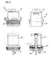
- FIG. 3 to 11 explains how in such a constructed filter device 10, the associated filter element 16 can be replaced.
- the individual figures each show on the left a side view of the respective mounting state, while on the right side of the figures in each case a longitudinal section of the corresponding mounting state is shown.
- Fig. 3 to 6 Sequentially represent steps of disassembly of the filter element 16 from the filter device 10.
- Fig. 4 shown how the filter housing 12 is unscrewed with its external thread 28 from the housing cover 14 and its internal thread 34.
- the external thread 38 is designed with its length C so long that the filter element 16 is still supported on the mandrel 36 after this screwing.
- the filter housing 12 is then, as in Fig. 5 shown withdrawn from the filter element 16.
- FIG. 7 to 11 show the installation of a new filter element 16 in the finally fully assembled filter device 10.
- this assembly is first according to Fig. 7 screwed the filter element 16 with one of its internal thread 48 on the external thread 38 of the housing cover 14.
- the internal thread 48 can be completely or as far as possible screwed (as in Fig. 8 , shown on the right).
- a partial screwing (as in Fig. 9 , illustrated on the right). With the following screwing in (see Fig.
- the passage opening 22 in the housing bottom 18 is designed so large that in the in Fig. 11 illustrated assembled state through the through hole 22 into which this opening opposite internal thread 48 of the filter element 16, a component can be screwed.
- a component can advantageously be fastened to the filter device 10 (in particular independently of the features of claim 1 characterizing the invention described above).
- Such a component can be particularly advantageous a pressure sensor.
Description
Die Erfindung betrifft eine Filtereinrichtung, insbesondere eine Kraftstofffiltereinrichtung für eine Brennkraftmaschine, mit einem Filtergehäuse, das durch einen Gehäusedeckel verschlossen ist und in dem ein Filterelement derart angeordnet ist, dass nach einem Lösen des Gehäusedeckels vom Filtergehäuse, das Filterelement weiterhin am Gehäusedeckel gehaltert ist.The invention relates to a filter device, in particular a fuel filter device for an internal combustion engine, with a filter housing which is closed by a housing cover and in which a filter element is arranged such that after a release of the housing cover from the filter housing, the filter element is further supported on the housing cover.
Es sind Filtereinrichtungen bekannt, bei denen ein in einem Filtergehäuse angeordnetes Filterelement beim Abnehmen eines zugehörigen Gehäusedeckels aus dem Filtergehäuse mit entnommen werden kann. So ist in
Die
Es ist eine Aufgabe der Erfindung eine eingangs genannte Filtereinrichtung derart zu verbessern, dass die oben genannten Nachteile überwunden und insbesondere ein Anbau sowie ein Wechsel des Filterelements mit geringem Aufwand und ohne eine Gefahr der Beschädigung von Bauteilen der Filtereinrichtung möglich ist.It is an object of the invention to improve a filter device mentioned above such that the above-mentioned disadvantages overcome and in particular an attachment and a change of the filter element with little effort and without a risk of damage to components of the filter device is possible.
Die Aufgabe ist erfindungsgemäß mit einer gattungsgemäßen Filtereinrichtung gelöst, bei der das Filterelement an dem Gehäusedeckel mit einer Schraubverbindung gehaltert ist.The object is achieved according to the invention with a generic filter device in which the filter element is mounted on the housing cover with a screw connection.
Die Schraubverbindung zwischen Filterelement und Gehäusedeckel erscheint gegenüber einer zwischen dem Filterelement und dem Gehäusedeckel angeordneten Rastverbindung zunächst grundsätzlich eher nachteilig zu sein, weil sie erstens bei der Herstellung teuerer ist und zweitens eigentlich eine Schraubverbindung auch aufwendiger zu Montieren und zu Öffnen ist, als ein Rast- oder Clip-Verbindung. Die Schraubverbindung zwischen Filterelement und Gehäusedeckel führt aber im Vergleich zu Rastverbindungen zu einer erheblich steiferen und bruchsichereren Verbindung der beteiligten Bauteile und schafft damit dort einen derart großen Vorteil, dass die sich gegebenenfalls ergebenden Kostennachteile überwunden werden können. Auch der Zusatzaufwand hinsichtlich der Montage ist bei der erfindungsgemäßen Filtereinrichtung vergleichsweise gering, Die Demontage des erfindungsgemäßen Filterelements, so hat sich gezeigt ist sogar besonders einfach, weil sich die erfindungsgemäße Schraubverbindung selbst nach langer Betriebszeit der Filtereinrichtung störungsfrei und ohne Gefahr von Beschädigung öffnen lässt.The screw connection between the filter element and the housing cover initially appears to be rather disadvantageous compared to a latching connection arranged between the filter element and the housing cover, because firstly it is more expensive to manufacture and secondly actually a screw connection is also more expensive to assemble and to open than a latching connection. or clip connection. However, the screw connection between the filter element and the housing cover leads compared to locking connections to a significantly stiffer and unbreakable connection of the components involved, thus creating there such a great advantage that any resulting cost disadvantages can be overcome. The additional effort in terms of assembly is comparatively low in the filter device according to the invention, the disassembly of the filter element according to the invention, so has it is even particularly easy because even after a long period of operation of the filter device, the screw connection according to the invention can be opened trouble-free and without danger of damage.
Dadurch dass das Filterelement zwei entgegen gesetzte Stirnseiten aufweist, von denen im eingebauten Zustand eine zum Gehäusedeckel und eine zum Filtergehäuse gerichtet ist, und an jeder dieser Stirnseiten ein Gewinde zum möglichen Verbinden mit dem Gehäusedeckel vorgesehen ist, gestaltet sich die Montage und auch der Austausch des Filterelements besonders einfach. Ein derart symmetrisch gestaltetes Filterelement kann bei der Montage besonders leicht automatisch zugeführt und auch verbaut werden, weil es nicht verkehrt herum eingebaut werden kann.The fact that the filter element has two opposite end faces, one of which is directed to the housing cover and a filter housing in the installed state, and at each of these end faces a thread for possible connection to the housing cover is provided, the assembly and the replacement of the designed Filter element particularly easy. Such a symmetrically designed filter element can be easily automatically supplied during assembly and also installed, because it can not be installed upside down.
Um über die Lebensdauer der erfindungsgemäßen Filtereinrichtung hinweg deren Dichtheit sicherstellen zu können, ist es von Vorteil, wenn gemäß einer vorteilhaften Weiterbildung der erfindungsgemäßen Lösung der Gehäusedeckel an dem Filtergehäuse mit einer Schraubverbindung befestigt ist. Eine derartige Schraubverbindung bringt es aber mit sich, dass der Gehäusedeckel und damit auch das daran befestigte Filterelement beim Auf- und Abschrauben am Filtergehäuse gedreht werden. Da zugleich aber auch das Filterelement in dem Filtergehäuse an einem Dichtsitz aufgeschoben werden muss, ist eine Drehbewegung des Filterelements grundsätzlich von Nachteil. Durch den Reibwiderstand an dem genannten Dichtsitz kann es nämlich passieren, dass die Dichtwirkung negativ beeinflusst oder die Schraubverbindung zwischen Gehäusedeckel und Filterelement gelöst wird, nämlich gerade dann, wenn diese Schraubverbindung die gleiche Gewinderichtung (d.h. Links- oder Rechtsgewinde) aufweist, wie die Schraubverbindung zwischen Filtergehäuse und Gehäusedeckel. Um ein derartiges Lösen der Schraubverbindung zwischen Gehäusedeckel und Filterelement zu verhindern, kann vorteilhaft die Gewinderichtung der Schraubverbindung zwischen Gehäusedeckel und Filtergehäuse entgegengesetzt zu der Gewinderichtung der Schraubverbindung zwischen Filterelement und Gehäusedeckel gestaltet sein.In order to be able to ensure their tightness over the life of the filter device according to the invention, it is advantageous if, according to an advantageous development of the solution according to the invention, the housing cover is fastened to the filter housing with a screw connection. Such a screw connection, however, entails that the housing cover and thus also the filter element fastened thereto are rotated during screwing on and off the filter housing. Since at the same time but also the filter element in the filter housing must be pushed to a sealing seat, a rotational movement of the filter element is fundamentally disadvantageous. By the frictional resistance of said sealing seat, it can happen that the sealing effect is adversely affected or the screw connection between the housing cover and filter element is released, namely, just when this screw has the same thread direction (ie left or right-hand thread), as the screw connection between Filter housing and housing cover. In order to prevent such a loosening of the screw connection between the housing cover and the filter element, the thread direction of the screw connection between the housing cover and the filter housing can advantageously be designed opposite to the thread direction of the screw connection between the filter element and the housing cover.
Eine derartige Weiterbildung bringt es aber mit sich, dass gegebenenfalls bei einem Aufschrauben des Gehäusedeckels auf das Filtergehäuse das Filterelement mit seiner Schraubverbindung zusätzlich in Richtung auf die festgeschraubte Lage bewegt und dadurch diese Schraubverbindung ungebührend fest angezogen wird. Solche Probleme treten hingegen bei einer weiteren vorteilhaften Ausgestaltung der Erfindung nicht auf, bei der die Schraubverbindung zwischen Filterelement und Gehäusedeckel sowie die Schraubverbindung zwischen Gehäusedeckel und Filtergehäuse eine gemeinsame Drehachse aufweisen und in Richtung der gemeinsamen Drehachse die axiale Erstreckung der Schraubverbindung zwischen Filterelement und Gehäusedeckel länger gestaltet ist, als die axiale Erstreckung der Schraubverbindung zwischen Gehäusedeckel und Filtergehäuse. Bei einer derartigen Ausgestaltung kann dann nämlich das Gewinde der Schraubverbindung zwischen Gehäusedeckel und Filtergehäuse (zum Lösen bzw. Befestigen) jeweils mit gleicher Drehrichtung gestaltet sein, wie das Gewinde der Schraubverbindung zwischen Filterelement und Gehäusedeckel. Dies ist möglich, weil das Filterelement, das während des Auf- oder Abschraubens des Gehäusedeckels (aufgrund der Reibung am Dichtsitz zwischen Filtergehäuse und Filterelement) im Filtergehäuse gebremst ist und sich daher (und wegen der gleichen Gewinderichtung) nicht mit dem Gehäusedeckel mitdreht, sich nicht vollständig von der besonders lang gestalteten Schraubverbindung zwischen Filterelement und Gehäusedeckel ablösen kann. Im Falle eines Abschraubens des Gehäusedeckels vom Filtergehäuse bedeutet dies konkret, dass das Filterelement noch am Gehäusedeckel befestigt ist, wenn die Schraubverbindung zwischen Gehäusedeckel und Filtergehäuse bereits gelöst ist. Mit den derart gestalteten Schraubverbindungen ist also bewusst ein sich nicht mit dem Gehäusedeckel mitdrehendes Filterelement gestaltet.Such a development, however, entails that, if necessary, when the housing cover is screwed onto the filter housing, the filter element with its screw connection additionally moves in the direction of the bolted-on position and As a result, this screw is unduly tightened. Such problems do not occur in a further advantageous embodiment of the invention, in which the screw connection between the filter element and the housing cover and the screw connection between housing cover and filter housing have a common axis of rotation and designed in the direction of the common axis of rotation, the axial extent of the screw connection between the filter element and housing cover longer is, as the axial extent of the screw connection between the housing cover and the filter housing. In such an embodiment, namely, the thread of the screw connection between the housing cover and the filter housing (for releasing or securing) can be designed in each case with the same direction of rotation, as the thread of the screw connection between the filter element and housing cover. This is possible because the filter element, which is braked during mounting or unscrewing of the housing cover (due to friction at the sealing seat between filter housing and filter element) in the filter housing and therefore (and because of the same thread direction) does not rotate with the housing cover, not completely detached from the particularly long-shaped screw between the filter element and the housing cover. In the case of unscrewing the housing cover from the filter housing, this means concretely that the filter element is still attached to the housing cover when the screw connection between the housing cover and the filter housing is already solved. With the thus designed screw so deliberately not co-rotating with the housing cover filter element is designed.
Diese Lösung kann auch optimal an eine Abdichtung angepasst werden, welche für die ordnungsgemäße Funktion der Filtereinrichtung aus strömungstechnischen Gründen zwischen dem Filterelement und dem Filtergehäuse vorgesehen sein muss. Diese Abdichtung zwischen dem Filterelement und dem Filtergehäuse kann dabei, wie erwähnt besonders vorteilhaft als ein fluiddichter, insbesondere ein flüssigkeitsdichter Gleitsitz gestaltet sein.This solution can also be optimally adapted to a seal, which must be provided for the proper functioning of the filter device for fluidic reasons between the filter element and the filter housing. This seal between the filter element and the filter housing can be designed as mentioned particularly advantageous as a fluid-tight, in particular a liquid-tight sliding fit.
Darüber hinaus ist es bei einer derartigen erfindungsgemäßen Lösung immer von Vorteil, wenn das Filterelement bzw. das Filtergehäuse an dem Gleitsitz in Bezug auf die Drehachse der Schraubverbindung zwischen Filterelement und Gehäusedeckel sowohl verschiebbar als auch verdrehbar gestaltet ist. Ein allein für ein Verschieben vorgesehener Gleitsitz, welcher gemäß den oben beschriebenen Weiterbildungen möglich ist, führt allerdings zu einer erhöhten Dichtsicherheit und auch zu besonders geringen Schraubkräften für das Montieren und Demontieren des Gehäusedeckels (zusammen mit dem Filterelement) am Filtergehäuse.Moreover, in such a solution according to the invention is always advantageous if the filter element or the filter housing is designed to be both slidably and rotatably on the sliding seat with respect to the axis of rotation of the screw connection between the filter element and the housing cover. One alone for a move provided sliding fit, which is possible according to the developments described above, however, leads to increased sealing safety and also to very low screwing forces for mounting and dismounting the housing cover (together with the filter element) on the filter housing.
Um auch hinsichtlich der Filtrationswirkung und der restlichen Konstruktion des Filterelements die obengenannten Vorteile voll zur Geltung zu bringen, ist es besonders vorteilhaft, das Filterelement in Bezug auf die Mittelquerschnittsebene flächensymmetrisch zu gestalten. Ein hohe Filtrationsleistung bei besonders geringem Bauraum kann in Verbindung mit der erfindungsgemäß vorgesehenen Schraubverbindung ferner erzielt werden, wenn das Filterelement, sowie insbesondere auch das Filtergehäuse und/oder der Gehäusedeckel im Wesentlichen rotationssymmetrisch gestaltet sind.In order to fully bring out the above-mentioned advantages also with regard to the filtration effect and the remaining construction of the filter element, it is particularly advantageous to design the filter element with respect to the central cross-sectional plane in a surface-symmetrical manner. A high filtration performance with a particularly small installation space can also be achieved in connection with the screw connection provided according to the invention if the filter element, and in particular also the filter housing and / or the housing cover, are configured essentially rotationally symmetrical.
Die oben genannten Vorteile kommen besonders in Verbindung mit einem als Kraftstofffilter oder als Harnstofffilter, insbesondere für Kraftfahrzeuge gestalteten Filterelement zur Geltung, weil bei diesen Filtern regelmäßig Filterwechsel erfolgen müssen.The abovementioned advantages are particularly advantageous in connection with a filter element designed as a fuel filter or as a urea filter, in particular for motor vehicles, because filter filters must be carried out regularly with these filters.
Nachfolgend wird ein Ausführungsbeispiel einer erfindungsgemäßen Filtereinrichtung anhand der beigefügten schematischen Zeichnungen näher erläutert. Es zeigt:
- Fig. 1
- eine Seitenansicht einer erfindungsgemäßen Filtereinrichtung,
- Fig. 2
- den Schnitt II-II in
Fig. 1 , - Fig. 3 bis Fig. 6
- mehrere Schritte des Ausbaus eines sich zunächst in der Filtereinrichtung befindenden Filterelements und
- Fig. 7 bis Fig. 11
- mehrere Schritte des Einbaus eines sich abschließend in der Filtereinrichtung befindenden Filterelements.
- Fig. 1
- a side view of a filter device according to the invention,
- Fig. 2
- the section II-II in
Fig. 1 . - Fig. 3 to Fig. 6
- several steps of the expansion of a first located in the filter device filter element and
- Fig. 7 to Fig. 11
- several steps of installing a filter element finally located in the filter device.
In
Das Filtergehäuse 12 ist in seiner Grundform als ein Becher gestaltet, der einen Gehäuseboden 18 und eine daran am Umfang anschließende Ringwand 20 umfasst. An der Außenseite der Ringwand 20 befindet sich ein Anschluss 21 zum Einleiten eines zu filtrierenden Fluids, wie beispielsweise Kraftstoff oder Harnstoff. Die Ringwand 20 ist im Wesentlichen zylindrisch um eine Drehachse A gestaltet. Der Gehäuseboden 18 ist zentrisch von einer Durchgangsöffnung 22 durchsetzt, welche zum Einsetzen eines nicht dargestellten Drucksensors dient. In der Durchgangsöffnung ist an der zur Ringwand 20 gewandten Seite des Gehäusebodens 18 ein als kurzes Rohrstück gestalteter Dichtsitz 24 ausgebildet. Der Dichtsitz 24 weist an seiner Innenseite eine sich zylindrisch zur Drehachse A erstreckende Dichtfläche 26 auf. An dem vom Gehäuseboden 18 abgewandten Endbereich der Ringwand 20 ist diese mit einem Außengewinde 28 versehen, welches sich in Richtung der Drehachse A über eine Länge B der Ringwand 20 erstreckt.The
Der Gehäusedeckel 14 ist im Wesentlichen scheibenförmig mit einer im Wesentlichen kreisförmigen Deckelfläche 30 gestaltet, wobei vom Rand dieser Deckelfläche 30 ein im Vergleich zur Ringwand 20 kurzer Wandabschnitt 32 absteht. An diesem Wandabschnitt 32 ist ein Innengewinde 34 ausgebildet, welches in Richtung der Drehachse A ebenfalls eine Erstreckung der Länge B aufweist. Im Zentrum der Deckelfläche 30 ist diese von einem hohlzylindrischen Dorn 36 durchsetzt, der außenseitig vom Gehäusedeckel 14 als ein Fluidauslass für die Filtereinrichtung 10 ausgebildet ist. An der zum Filtergehäuse 12 gewandten Seite, welche also die Innenseite des Gehäusedeckels 14 darstellt, ist der Dorn 36 an einem an die Deckelfläche 30 anschließenden Abschnitt mit einem Außengewinde 38 gestaltet. Dieses Außengewinde 38 weist in Richtung der Drehachse A eine Länge C auf, welche etwa dem Zweifachen der Länge B entspricht. Der Dorn 36 ist ferner ein kurzes Stück von einem an die Deckelfläche 30 anschließenden hohlzylindrischen Dichtsitz 40 umgeben, an dessen Innenseite eine zylindrische Dichtfläche 42 ausgebildet ist.The
Das Filterelement 16 umfasst im Wesentlichen ein hohlzylindrisch gestaltetes Filtergitter 44, an dessen beiden Stirnseiten jeweils ein Anschlussring 46 fluiddicht angesetzt ist. Im Zentrum jedes dieser Anschlussringe 46 ist ein hohlzylindrischer Abschnitt vorgesehen, dessen innenseitige Durchgangsöffnung mit einem Innengewinde 48 gestaltet ist. Dieses Innengewinde 48 weist in Richtung der Drehachse A eine Länge D auf, welche kleiner als die Länge B ist. Außenseitig ist jeder der hohlzylindrischen Abschnitte mit einem Dichtring 50 versehen, welcher ortsfest an dem zugehörigen hohlzylindrischen Abschnitt gehalten ist.The
Bei montierter Filtereinrichtung 10, so wie sie in
Nachfolgend wird anhand der
Die
Bei diesem Abschrauben des Filtergehäuses 12 ist im Inneren des Filtergehäuses 12 zwischen dem Dichtsitz 26 und dem bezogen auf die Figuren oberen Dichtring 50 das Filterelement 16 einer Haftreibung unterworfen, wodurch das Filterelement 16 beim Abdrehen des Filtergehäuses 12 mit diesem mitgedreht wird. Dadurch wird auch das Innengewinde 48 des Filterelements 16 zumindest über die Länge B von dem Außengewinde 38 des Gehäusedeckels 14 bzw. dessen Dorn 36 geschraubt.In this unscrewing of the
Das Außengewinde 38 ist mit seiner Länge C jedoch derart lang gestaltet, dass das Filterelement 16 auch nach diesem Schraubvorgang weiterhin an dem Dorn 36 gehaltert ist. Das Filtergehäuse 12 wird dann, wie in
Nach dem Entfernen des Filtergehäuses 12 kann, wie in
Die
Abschießend sei angemerkt, dass die Durchgangsöffnung 22 im Gehäuseboden 18 derart groß gestaltet ist, dass bei dem in
Claims (8)
- Filter assembly (10), in particular fuel filter assembly for an internal combustion engine, with a filter housing (12) which is closed by a housing cover (14) and in which a filtering element (16) is secured on the housing cover (14) by a screw connection (38, 48), characterized in that the filtering element (16) has two opposite end sides, of which, in the installed state, one is directed towards the housing cover (14) and one towards the filter housing (12), and a thread (48) for the possible connection to the housing cover (14) is provided on each of said end sides.
- Filter assembly according to Claim 1, characterized in that the filtering element (16) is arranged in the filter housing (12) in such a manner that, following detachment of the housing cover (14) from the filter housing (12), the filtering element (16) continues to be secured on the housing cover (14).
- Filter assembly according to Claim 1 or 2, characterized in that the housing cover (14) is fastened to the filter housing (12) with a screw connection (28, 34).
- Filter assembly according to Claim 3, characterized in that the screw connection (38, 48) between the filtering element (16) and housing cover (14), and the screw connection (28, 34) between the housing cover (14) and filter housing (12) have a common axis of rotation (A) and, in the direction of said axis of rotation (A), the axial extent (C) of the screw connection (38, 48) between the filtering element (16) and housing cover (14) is configured to be longer than the axial extent (B) of the screw connection (28, 34) between the housing cover (14) and filter housing (12).
- Filter assembly according to one of Claims 1 to 4, characterized in that a fluid-tight, in particular liquid-tight, sliding seat (26, 50) is formed between the filtering element (16) and the filter housing (12).
- Filter assembly according to Claim 5, characterized in that the filtering element (16) or the filter housing (12) is formed on the sliding seat (26, 50) so as to be displaceable and/or rotatable with respect to the axis of rotation (A) of the screw connection (38, 48) between the filtering element (16) and housing cover (14).
- Filter assembly according to one of Claims 1 to 6, characterized in that the filtering element (16) is formed as a fuel filter.
- Filter assembly according to one of Claims 1 to 6, characterized in that the filtering element (16) is formed as a urea filter.
Applications Claiming Priority (2)
| Application Number | Priority Date | Filing Date | Title |
|---|---|---|---|
| DE102005026292A DE102005026292A1 (en) | 2005-06-08 | 2005-06-08 | Filter device with a filter element |
| EP05112147A EP1731210B1 (en) | 2005-06-08 | 2005-12-14 | Filter assembly with a filtering element |
Related Parent Applications (2)
| Application Number | Title | Priority Date | Filing Date |
|---|---|---|---|
| EP05112147A Division EP1731210B1 (en) | 2005-06-08 | 2005-12-14 | Filter assembly with a filtering element |
| EP05112147.3 Division | 2005-12-14 |
Publications (2)
| Publication Number | Publication Date |
|---|---|
| EP2062633A1 EP2062633A1 (en) | 2009-05-27 |
| EP2062633B1 true EP2062633B1 (en) | 2010-10-27 |
Family
ID=36808346
Family Applications (2)
| Application Number | Title | Priority Date | Filing Date |
|---|---|---|---|
| EP05112147A Active EP1731210B1 (en) | 2005-06-08 | 2005-12-14 | Filter assembly with a filtering element |
| EP09100154A Active EP2062633B1 (en) | 2005-06-08 | 2005-12-14 | Filter assembly with a filtering element |
Family Applications Before (1)
| Application Number | Title | Priority Date | Filing Date |
|---|---|---|---|
| EP05112147A Active EP1731210B1 (en) | 2005-06-08 | 2005-12-14 | Filter assembly with a filtering element |
Country Status (2)
| Country | Link |
|---|---|
| EP (2) | EP1731210B1 (en) |
| DE (3) | DE102005026292A1 (en) |
Families Citing this family (8)
| Publication number | Priority date | Publication date | Assignee | Title |
|---|---|---|---|---|
| DE202006011990U1 (en) * | 2006-08-03 | 2007-12-20 | Mann + Hummel Gmbh | Filter unit with a radially split housing |
| CN102596355A (en) | 2009-11-12 | 2012-07-18 | 唐纳森公司 | Liquid filter construction for freezing environments |
| DE102010003961A1 (en) * | 2010-01-02 | 2011-07-07 | Hydac Filtertechnik GmbH, 66280 | Filter device and filter element for use in such a filter device |
| DE102010033682A1 (en) | 2010-08-06 | 2012-02-09 | Mahle International Gmbh | fluid filter |
| CN102562218A (en) * | 2011-12-13 | 2012-07-11 | 蚌埠首创滤清器有限公司 | Replaceable screwed filter |
| DE102015213261A1 (en) * | 2015-07-13 | 2017-01-19 | Mahle International Gmbh | filtering device |
| DE102015012558A1 (en) * | 2015-09-25 | 2017-03-30 | Hydac Filtertechnik Gmbh | filter means |
| US20200114288A1 (en) | 2018-10-10 | 2020-04-16 | Schroeder Industries, Llc | Filter assembly with authenticating filter element coupling and replaceable drop-in twist locking filter element therefor |
Family Cites Families (5)
| Publication number | Priority date | Publication date | Assignee | Title |
|---|---|---|---|---|
| US5355860A (en) | 1992-07-09 | 1994-10-18 | Ekstam Charles L | Fuel delivery system for diesel engines |
| US5879543A (en) | 1994-04-13 | 1999-03-09 | Amini; Bijan | Filter and dehydrator apparatus with threaded collar |
| DE19602082B4 (en) | 1996-01-20 | 2004-04-08 | Mann + Hummel Gmbh | Fuel module |
| JP3983912B2 (en) | 1998-01-30 | 2007-09-26 | 日本ゼオライト株式会社 | Porous ceramic for alkaline ion water production, method for producing the porous ceramic, and alkaline ion water generator |
| US6217763B1 (en) * | 1999-08-11 | 2001-04-17 | Usf Filtration And Separation Group, Inc. | Back-flushable filter cartridge assemblies |
-
2005
- 2005-06-08 DE DE102005026292A patent/DE102005026292A1/en not_active Ceased
- 2005-12-14 DE DE502005010460T patent/DE502005010460D1/en active Active
- 2005-12-14 EP EP05112147A patent/EP1731210B1/en active Active
- 2005-12-14 EP EP09100154A patent/EP2062633B1/en active Active
- 2005-12-14 DE DE502005007408T patent/DE502005007408D1/en active Active
Also Published As
| Publication number | Publication date |
|---|---|
| EP1731210B1 (en) | 2009-06-03 |
| DE102005026292A1 (en) | 2006-12-14 |
| EP2062633A1 (en) | 2009-05-27 |
| EP1731210A1 (en) | 2006-12-13 |
| DE502005010460D1 (en) | 2010-12-09 |
| DE502005007408D1 (en) | 2009-07-16 |
Similar Documents
| Publication | Publication Date | Title |
|---|---|---|
| EP2062633B1 (en) | Filter assembly with a filtering element | |
| DE102012000876B3 (en) | Liquid filter and filter element of a liquid filter | |
| DE102004058885B4 (en) | Füssigkeitsfilter | |
| EP3329979B1 (en) | Filter housing and filter insert | |
| DE102009048412B3 (en) | Filter system for filtration of e.g. diesel in motor vehicle, has safety device, and elastic safety-spring element located in bowl when edge-track section is arranged at head or located at head when edge section is arranged in bowl | |
| EP2102484B1 (en) | Fuel filter of a vehicle internal combustion engine | |
| DE102011077798A1 (en) | Fluid filter with an eccentric fluid drainage channel | |
| EP2808069B1 (en) | Filter device, in particular fluid filter | |
| WO2014082762A1 (en) | Filter, filter element, filter housing and discharge device of a filter | |
| DE4124323C2 (en) | Filters for liquids to be screwed onto a mounting head | |
| EP3458175B1 (en) | Filter device | |
| EP3691769B1 (en) | Filter element with venting function for suspension on a filter head, and filter system | |
| EP3668629B1 (en) | Filter system, filter and method | |
| EP3535039B1 (en) | Filter device | |
| WO2017050412A1 (en) | Filter device with coupling element | |
| EP3558485A1 (en) | Fluid outflow control by means of a sealing assembly | |
| WO2018127318A1 (en) | Valve arrangement | |
| EP3727641B1 (en) | Filter system with non-return valve and filter element | |
| WO2017036856A1 (en) | Fluid filter and filter insert for the same | |
| WO2020201483A1 (en) | Filter with a two-part filter housing and with a filter insert with a seal support, and filter insert for the filter | |
| EP3544714B1 (en) | Filter element and fluid filter comprising a rotatable bayonet ring | |
| EP4088801B1 (en) | Filter device | |
| WO2018065138A1 (en) | Liquid filter | |
| DE102008003740A1 (en) | Device e.g. for actuating valve, has valve actuation equipment, flow channel with first channel section and another channel section and first section has functional unit with sealed passage opening | |
| DE102021002024A1 (en) | filter device |
Legal Events
| Date | Code | Title | Description |
|---|---|---|---|
| PUAI | Public reference made under article 153(3) epc to a published international application that has entered the european phase |
Free format text: ORIGINAL CODE: 0009012 |
|
| AC | Divisional application: reference to earlier application |
Ref document number: 1731210 Country of ref document: EP Kind code of ref document: P |
|
| AK | Designated contracting states |
Kind code of ref document: A1 Designated state(s): DE FR IT SE |
|
| 17P | Request for examination filed |
Effective date: 20091127 |
|
| 17Q | First examination report despatched |
Effective date: 20091228 |
|
| AKX | Designation fees paid |
Designated state(s): DE FR IT SE |
|
| GRAP | Despatch of communication of intention to grant a patent |
Free format text: ORIGINAL CODE: EPIDOSNIGR1 |
|
| GRAS | Grant fee paid |
Free format text: ORIGINAL CODE: EPIDOSNIGR3 |
|
| GRAA | (expected) grant |
Free format text: ORIGINAL CODE: 0009210 |
|
| AC | Divisional application: reference to earlier application |
Ref document number: 1731210 Country of ref document: EP Kind code of ref document: P |
|
| AK | Designated contracting states |
Kind code of ref document: B1 Designated state(s): DE FR IT SE |
|
| REF | Corresponds to: |
Ref document number: 502005010460 Country of ref document: DE Date of ref document: 20101209 Kind code of ref document: P |
|
| PG25 | Lapsed in a contracting state [announced via postgrant information from national office to epo] |
Ref country code: SE Free format text: LAPSE BECAUSE OF FAILURE TO SUBMIT A TRANSLATION OF THE DESCRIPTION OR TO PAY THE FEE WITHIN THE PRESCRIBED TIME-LIMIT Effective date: 20101027 |
|
| PLBE | No opposition filed within time limit |
Free format text: ORIGINAL CODE: 0009261 |
|
| STAA | Information on the status of an ep patent application or granted ep patent |
Free format text: STATUS: NO OPPOSITION FILED WITHIN TIME LIMIT |
|
| 26N | No opposition filed |
Effective date: 20110728 |
|
| REG | Reference to a national code |
Ref country code: DE Ref legal event code: R097 Ref document number: 502005010460 Country of ref document: DE Effective date: 20110728 |
|
| REG | Reference to a national code |
Ref country code: FR Ref legal event code: PLFP Year of fee payment: 11 |
|
| REG | Reference to a national code |
Ref country code: FR Ref legal event code: PLFP Year of fee payment: 12 |
|
| REG | Reference to a national code |
Ref country code: FR Ref legal event code: PLFP Year of fee payment: 13 |
|
| PGFP | Annual fee paid to national office [announced via postgrant information from national office to epo] |
Ref country code: IT Payment date: 20221230 Year of fee payment: 18 Ref country code: DE Payment date: 20230223 Year of fee payment: 18 |
|
| PGFP | Annual fee paid to national office [announced via postgrant information from national office to epo] |
Ref country code: FR Payment date: 20231220 Year of fee payment: 19 |