EP2062011B1 - Strömungsmesser - Google Patents
Strömungsmesser Download PDFInfo
- Publication number
- EP2062011B1 EP2062011B1 EP07803742.1A EP07803742A EP2062011B1 EP 2062011 B1 EP2062011 B1 EP 2062011B1 EP 07803742 A EP07803742 A EP 07803742A EP 2062011 B1 EP2062011 B1 EP 2062011B1
- Authority
- EP
- European Patent Office
- Prior art keywords
- hole
- flow meter
- section
- flow
- dividing
- Prior art date
- Legal status (The legal status is an assumption and is not a legal conclusion. Google has not performed a legal analysis and makes no representation as to the accuracy of the status listed.)
- Active
Links
- 238000007789 sealing Methods 0.000 claims description 29
- 238000003825 pressing Methods 0.000 claims description 3
- 238000005259 measurement Methods 0.000 description 8
- 238000000465 moulding Methods 0.000 description 4
- 239000000463 material Substances 0.000 description 3
- 238000000034 method Methods 0.000 description 3
- 230000003292 diminished effect Effects 0.000 description 2
- 239000000203 mixture Substances 0.000 description 2
- 239000004033 plastic Substances 0.000 description 2
- 239000011435 rock Substances 0.000 description 2
- XLYOFNOQVPJJNP-UHFFFAOYSA-N water Substances O XLYOFNOQVPJJNP-UHFFFAOYSA-N 0.000 description 2
- 238000004873 anchoring Methods 0.000 description 1
- 238000005452 bending Methods 0.000 description 1
- 230000015572 biosynthetic process Effects 0.000 description 1
- 239000013013 elastic material Substances 0.000 description 1
- 238000002474 experimental method Methods 0.000 description 1
- 239000012212 insulator Substances 0.000 description 1
- 239000007788 liquid Substances 0.000 description 1
- 238000004519 manufacturing process Methods 0.000 description 1
- 238000005192 partition Methods 0.000 description 1
- 238000005070 sampling Methods 0.000 description 1
- 239000007787 solid Substances 0.000 description 1
- 239000002699 waste material Substances 0.000 description 1
Images


Classifications
-
- G—PHYSICS
- G01—MEASURING; TESTING
- G01V—GEOPHYSICS; GRAVITATIONAL MEASUREMENTS; DETECTING MASSES OR OBJECTS; TAGS
- G01V11/00—Prospecting or detecting by methods combining techniques covered by two or more of main groups G01V1/00 - G01V9/00
- G01V11/002—Details, e.g. power supply systems for logging instruments, transmitting or recording data, specially adapted for well logging, also if the prospecting method is irrelevant
-
- E—FIXED CONSTRUCTIONS
- E21—EARTH OR ROCK DRILLING; MINING
- E21B—EARTH OR ROCK DRILLING; OBTAINING OIL, GAS, WATER, SOLUBLE OR MELTABLE MATERIALS OR A SLURRY OF MINERALS FROM WELLS
- E21B47/00—Survey of boreholes or wells
- E21B47/10—Locating fluid leaks, intrusions or movements
-
- G—PHYSICS
- G01—MEASURING; TESTING
- G01F—MEASURING VOLUME, VOLUME FLOW, MASS FLOW OR LIQUID LEVEL; METERING BY VOLUME
- G01F1/00—Measuring the volume flow or mass flow of fluid or fluent solid material wherein the fluid passes through a meter in a continuous flow
-
- G—PHYSICS
- G01—MEASURING; TESTING
- G01V—GEOPHYSICS; GRAVITATIONAL MEASUREMENTS; DETECTING MASSES OR OBJECTS; TAGS
- G01V9/00—Prospecting or detecting by methods not provided for in groups G01V1/00 - G01V8/00
- G01V9/02—Determining existence or flow of underground water
-
- Y—GENERAL TAGGING OF NEW TECHNOLOGICAL DEVELOPMENTS; GENERAL TAGGING OF CROSS-SECTIONAL TECHNOLOGIES SPANNING OVER SEVERAL SECTIONS OF THE IPC; TECHNICAL SUBJECTS COVERED BY FORMER USPC CROSS-REFERENCE ART COLLECTIONS [XRACs] AND DIGESTS
- Y02—TECHNOLOGIES OR APPLICATIONS FOR MITIGATION OR ADAPTATION AGAINST CLIMATE CHANGE
- Y02A—TECHNOLOGIES FOR ADAPTATION TO CLIMATE CHANGE
- Y02A90/00—Technologies having an indirect contribution to adaptation to climate change
- Y02A90/30—Assessment of water resources
Definitions
- the invention relates to a flow meter as defined in the preamble of claim 1.
- US 6076398 A discloses a flowmeter for measuring flow of liquid in a hole bored in the ground.
- the flowmeter comprises dividing elements in the form of ridges or partitions, dividing the measurement space into at least three sectors.
- US 5804714 A discloses a flowmeter designed to find areas containing currents in a hole bored in rock. The flowmeter comprise duct allowing measurement of flow between e measurement section and the hole portion outside of it.
- US 6581455 B1 discloses an apparatus for testing an underground formation.
- the apparatus comprises an extendable gripper element for anchoring the apparatus during testing and sampling operations.
- the objective of the invention is to eliminate the drawbacks referred to above.
- One specific objective of the invention is to disclose a novel flow meter which can be used to measure in a simple and quick manner even smaller flows passing through the borehole in transverse clefts.
- Another objective of the invention is to disclose a flow meter which can also be used to quickly and easily locate such clefts and fractures which require transverse flow measuring.
- the flow meter in accordance with the invention is characterized by what has been presented in claim 1.
- the flow meter in accordance with the invention is designated to be used in a hole drilled in the bedrock in order to measure stream flows in fractures and clefts in the bedrock which are transversal to the hole, i.e. to measure both directions and rates of the flows in such clefts.
- the flow meter comprises an elongated body having a cross-section which is substantially smaller than the diameter of the hole, and separating members placed at a distance from each other in the longitudinal direction of the body, in order to separate in a substantially pressure-tight manner a section to be examined from the other parts of the hole.
- the dividing members are formed of thin and elastic sealing strips, which are fixed to the body and, being substantially perpendicular to the surface of the body, have been arranged to surround and delimit the sectors and to be pressed in the hole against the surface thereof into a sufficient tightness.
- the width of the sealing strips is thereby so sized that that they are somewhat remoldable and become bent against the surface of the hole as their elastic structure presses the bent outer edges against the drilled surface of the rock.
- the invention derives thus from the realization that in conducting transverse flow measurements, the prevailing pressure differences in the transverse direction of the hole are so small that even relatively subtle pressure sealings are sufficient to separate the occurring flows from each other with the accuracy required for the measurements.
- a simple elastic strip made from suitable rubber or plastic and also having its outer edge preferably diminished to bend slightly, forms a sufficient sealing between the measure sectors.
- the sealing strip is formed of a continuous link, i.e. a single and uniform sealing strip made from one piece of material separately surrounds both sectors.
- the sealing strip thereby comprises two straight dividing walls in the longitudinal direction of the body, and ring-shaped, semicircular end walls connecting them at the ends.
- two opposing sector areas are formed in the examined hole, so that the flow is only able to pass between them in the hole via a measure channel which intersects the body.
- the sealing strips can be fixed to the body of the flow meter in many different ways per se.
- the inner edges of the dividing wall and the end wall, which are placed against the body comprise enlargements which stiffen and support the otherwise relatively thin and flexible sealing strip. They can thereby be fixed to the body by means of pressing and sealing joints, i.e. for example by means of a molding which is equally long as the dividing wall, the molding being screwed on to the body as the enlargement of the dividing wall becomes pressed and tightened between the body and the molding.
- the opposing and adjacent dividing walls of different sectors can be conveniently bent into a diagonal position away from each other. It has been noted that this clearly improves the sealing between the sectors.
- the separating members be elastic and discoidal rings, arranged in the longitudinal direction of the body to curve in the same direction at the edges. Such separating members remain always fit for use and pressed sufficiently tightly against the surface of the hole.
- the flow meter comprises a second section delimited by auxiliary separating members, in which section there have been arranged measuring means for measuring the conductivity of the bedrock around the hole.
- the length of this second section is significantly smaller than that of the actual section to be examined.
- Water-filled clefts in the bedrock contribute significantly to local conductivity of the bedrock, so that by measuring the conductivity, the clefts can be located relatively accurately in the borehole.
- the flow meter can be easily and with sufficient accuracy moved so that the observed cleft is sure to be included in the actual measure section.
- the entire hole can be measured and the clefts which are observed therein registered first with sufficient accuracy, and the flows therein measured only after this, one observed cleft at a time.
- the flow meter in accordance with the invention has considerable advantages compared to prior art. Thanks to the invention, flows in the fractures of the bedrock, as well as the rates and directions thereof, can be examined in a quick and accurate manner in deep holes drilled in the bedrock.
- Figs. 1-3 represent one flow meter in accordance with the invention.
- the flow meter comprises an elongated body 3 having a circular cross-section, with two pairs of discoidal separating members 4 made from elastic material and known per se in the field positioned at a distance from each other, so as to separate from a hole 1 in the bedrock, in a substantially pressure-tight manner, a section to be examined.
- traditional expandable plugs can be used when necessary.
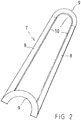
- Two sealing strips 7, represented more specifically in Fig. 2 have been placed around the body 3 in the examined section.
- the sealing strip 7 is formed of elastic and flexible rubber or plastic material and has two straight and parallel dividing walls 8 and two ring-shaped end walls 9 which connect the dividing walls together at both ends. In this way, both sealing strips separately form a semicircular sector, which substantially extends from one pair of separating members to the other, i.e. over the entire examined section.
- the sealing strip is a continuous link made from one piece of uniform material.
- the sealing strip is evenly wide and has been sized such that, when fixed in place to the body 3, and the flow meter being inserted into the measure hole, it clearly comes into contact with the surface of the hole and rests against it, bending at the outer edges.
- the edge of the strip has also been diminished so that it becomes extremely flexible and seals the delimited area in the measure hole, practically entirely preventing flows between the sealing strip and the surface of the hole. In this way, two sectors having semicircular cross-sections are formed in the hole, so that the flow is only able to pass between them via a measure channel 6 which intersects the body 3.
- a suitable flow meter for measuring both the direction and the rate of water flows passing through it.
- the lower edges of the sealing strips comprise enlargements 10, by which they have been fixed to the body 3 throughout their straight dividing walls 8.
- the sealing strips 7 are fixed by the enlargements 8 by pressing the enlargements against the surface of the body, for example by means of a suitable molding 14. This causes the dividing walls of different sealing strips, which are positioned opposite each other, to bend away from each other into a diagonal position which, based on practical experiments, clearly improves the sealing properties of the sealing strips.
- the measure section between the separating members 4 has the length of 0,5-1m, however, the depth of the measure hole may also be several kilometers. This is why it is not reasonable to measure accurately the entire hole, but instead the potential sections to be measured, i.e. the fracture areas 2, are to be located first.
- the flow meter also comprises auxiliary separating members 11, i.e. a third pair of discoidal separating members, above the upper pair of separating members 15. These delimit another substantially pressure-tight section 12 above the measure section, i.e. above the previously mentioned upper pair of separating members 15, in which section potential measuring means 13 have been placed.
- the potential measuring means 13 are used to form a voltage difference over and past the pair of separating members 15 via the bedrock.
- the dry and solid bedrock is a relatively good insulator, but in case of a wet fracture, the prevailing voltage of the pair of separating members 15 substantially changes.
- this voltage change and moving the flow meter in the hole it is, for example, possible to first measure and register relatively quickly all fractures in the examined hole which require flow measuring, and thereafter quickly move the flow meter in the hole from one fracture to another in order to perform the measurements.
- the sealing strips of the flow meter form continuously sufficiently sealed measure sectors, the flow meter in accordance with the invention can be used for quick and accurate measuring exactly at the required spots of the hole.
Landscapes
- Life Sciences & Earth Sciences (AREA)
- Physics & Mathematics (AREA)
- General Life Sciences & Earth Sciences (AREA)
- Geophysics (AREA)
- General Physics & Mathematics (AREA)
- Geology (AREA)
- Mining & Mineral Resources (AREA)
- Engineering & Computer Science (AREA)
- Fluid Mechanics (AREA)
- Environmental & Geological Engineering (AREA)
- Hydrology & Water Resources (AREA)
- Geochemistry & Mineralogy (AREA)
- Measuring Volume Flow (AREA)
- Geophysics And Detection Of Objects (AREA)
- Indicating Or Recording The Presence, Absence, Or Direction Of Movement (AREA)
- Investigation Of Foundation Soil And Reinforcement Of Foundation Soil By Compacting Or Drainage (AREA)
- Investigating Or Analyzing Materials By The Use Of Electric Means (AREA)
Claims (5)
- Durchflussmessgerät zur Verwendung in einem in den Felsen gebohrten Loch (1), um Strömungsflüsse in Felsrissen (2) zu messen, die quer zu dem Loch verlaufen, wobei das Durchflussmessgerät aufweist: einen länglichen Körper (3) mit einem Querschnitt, der im Wesentlichen kleiner ist als der Durchmesser des Loches; Trennelemente (4), die in einem Abstand zueinander in der longitudinalen Erstreckung des Loches angeordnet sind, um den untersuchten Abschnitt von den anderen Teilen des Loches in einer im Wesentlichen druckdichten Art und Weise voneinander zu trennen; Aufteilelemente (5) zum Aufteilen des untersuchten Abschnittes in zwei Sektoren in der longitudinalen Erstreckung des Loches; und einen Flusskanal (6), der sich durch den Körper erstreckt und mit einem Flusssensor zum Messen der Richtung und der Rate des Flusses zwischen den Sektoren ausgestattet ist, wobei die Aufteilelemente (5) aus dünnen und elastisch abdichtenden Streifen (7) gebildet sind, welche an dem Körper angebracht wurden und welche, im Wesentlichen senkrecht zu der Oberfläche des Körpers, angeordnet sind, um die Sektoren zu umgeben und zu begrenzen, dadurch gekennzeichnet, dass der abdichtende Streifen (7) zwei gerade Trennwände (8) in der longitudinalen Erstreckung des Körpers aufweist, und ringförmige Endwände (9) aufweist, die diese an den Enden verbinden.
- Durchflussmessgerät nach Anspruch 1, dadurch gekennzeichnet, dass jeder der abdichtenden Steifen (7) aus einer kontinuierlichen Verbindung besteht.
- Durchflussmessgerät nach einem der Ansprüche 1 oder 2, dadurch gekennzeichnet, dass die inneren Kanten der Trennwand (8) und der Endwand (9), positioniert gegen den Körper (3), Vergrößerungen (10) aufweisen, mittels derer sie an dem Körper mittels pressender und abdichtender Verbindungen angebracht sind.
- Durchflussmessgerät nach einem der Ansprüche 1-3, dadurch gekennzeichnet, dass die Trennelemente (4) elastische und scheibenförmige Ringe sind, welche in der longitudinalen Erstreckung des Körpers (3) angeordnet sind, so dass sie sich in der gleichen Richtung an ihren Rändern krümmen.
- Durchflussmessgerät nach einem der Ansprüche 1-4, dadurch gekennzeichnet, dass das Durchflussmessgerät eine zweite Sektion (12) aufweist, begrenzt durch zusätzliche Trennelemente (11), wobei in dem zweiten Abschnitt Messmittel (13) zum Messen der Leitfähigkeit des Felsens um das Loch herum angeordnet sind.
Applications Claiming Priority (2)
| Application Number | Priority Date | Filing Date | Title |
|---|---|---|---|
| FI20060812A FI120324B (fi) | 2006-09-12 | 2006-09-12 | Virtausmittari |
| PCT/FI2007/050481 WO2008031923A1 (en) | 2006-09-12 | 2007-09-11 | Flow meter |
Publications (3)
| Publication Number | Publication Date |
|---|---|
| EP2062011A1 EP2062011A1 (de) | 2009-05-27 |
| EP2062011A4 EP2062011A4 (de) | 2017-07-19 |
| EP2062011B1 true EP2062011B1 (de) | 2019-05-22 |
Family
ID=37067139
Family Applications (1)
| Application Number | Title | Priority Date | Filing Date |
|---|---|---|---|
| EP07803742.1A Active EP2062011B1 (de) | 2006-09-12 | 2007-09-11 | Strömungsmesser |
Country Status (8)
| Country | Link |
|---|---|
| US (1) | US8141436B2 (de) |
| EP (1) | EP2062011B1 (de) |
| JP (1) | JP5208114B2 (de) |
| KR (2) | KR101380699B1 (de) |
| CA (1) | CA2662108C (de) |
| FI (1) | FI120324B (de) |
| TW (1) | TWI555966B (de) |
| WO (1) | WO2008031923A1 (de) |
Families Citing this family (2)
| Publication number | Priority date | Publication date | Assignee | Title |
|---|---|---|---|---|
| EP2062060B1 (de) * | 2006-09-12 | 2020-01-08 | Posiva Oy | Messkopf und messverfahren |
| CN115263245B (zh) * | 2022-07-20 | 2024-06-14 | 安徽省皖北煤电集团有限责任公司 | 一种煤矿瓦斯抽采钻孔气体泄露检测定位装置 |
Family Cites Families (24)
| Publication number | Priority date | Publication date | Assignee | Title |
|---|---|---|---|---|
| US2709365A (en) * | 1949-07-18 | 1955-05-31 | Phillips Petroleum Co | Flowmeter |
| US3162042A (en) * | 1960-06-20 | 1964-12-22 | Schlumberger Well Surv Corp | Flowmeter apparatus |
| US3454085A (en) * | 1966-11-30 | 1969-07-08 | Otis Eng Corp | Well installation with plural flow meters |
| US4566317A (en) * | 1984-01-30 | 1986-01-28 | Schlumberger Technology Corporation | Borehole flow meter |
| FR2592426B1 (fr) * | 1985-12-30 | 1988-04-08 | Inst Francais Du Petrole | Dispositif et procede pour determiner l'orientation de fractures dans une formation geologique |
| US4786874A (en) * | 1986-08-20 | 1988-11-22 | Teleco Oilfield Services Inc. | Resistivity sensor for generating asymmetrical current field and method of using the same |
| US4896722A (en) * | 1988-05-26 | 1990-01-30 | Schlumberger Technology Corporation | Multiple well tool control systems in a multi-valve well testing system having automatic control modes |
| US4928758A (en) * | 1989-10-10 | 1990-05-29 | Atlantic Richfield Company | Downhole wellbore flowmeter tool |
| US5052220A (en) * | 1989-10-17 | 1991-10-01 | Schlumberger Technology Corporation | Apparatus for measurements related to fluid flow in a borehole |
| CA2034444C (en) * | 1991-01-17 | 1995-10-10 | Gregg Peterson | Method and apparatus for the determination of formation fluid flow rates and reservoir deliverability |
| RU2021501C1 (ru) | 1991-02-07 | 1994-10-15 | Василий Федорович Целищев | Глубинный расходомер |
| US5184677A (en) * | 1991-05-10 | 1993-02-09 | Gas Research Institute | Pass-through zone isolation packer and process for isolating zones in a multiple-zone well |
| US5455780A (en) * | 1991-10-03 | 1995-10-03 | Halliburton Company | Method of tracking material in a well |
| JP2987289B2 (ja) * | 1994-03-29 | 1999-12-06 | 哲雄 庄子 | 地下岩体の透水性の評価方法 |
| US6581455B1 (en) | 1995-03-31 | 2003-06-24 | Baker Hughes Incorporated | Modified formation testing apparatus with borehole grippers and method of formation testing |
| AU4450196A (en) * | 1996-01-12 | 1997-08-01 | Posiva Oy | Flow meter |
| KR100268514B1 (ko) * | 1996-01-15 | 2000-10-16 | 포시바 오이 | 유체흐름 측정방법 및 유량계 |
| FI110335B (fi) * | 1996-01-15 | 2002-12-31 | Posiva Oy | Virtausmittausmenetelmä ja virtausmittari |
| US5804741A (en) * | 1996-11-08 | 1998-09-08 | Schlumberger Industries, Inc. | Digital phase locked loop signal processing for coriolis mass flow meter |
| US6694824B2 (en) * | 2000-10-10 | 2004-02-24 | Matsushita Electric Industrial Co., Ltd. | Flow measuring device |
| US6758274B2 (en) * | 2001-03-20 | 2004-07-06 | Solinst Canada Limited | Sample extraction system for boreholes |
| CN1203294C (zh) * | 2002-08-08 | 2005-05-25 | 武汉长江仪器自动化研究所 | 坝基岩石灌浆水泥浆液流量计量方法 |
| GB2421573B (en) * | 2004-12-23 | 2009-09-23 | Schlumberger Holdings | Apparatus and method for formation evaluation |
| JP3950893B2 (ja) * | 2005-02-09 | 2007-08-01 | 核燃料サイクル開発機構 | 多区間水質連続モニタリング装置 |
-
2006
- 2006-09-12 FI FI20060812A patent/FI120324B/fi active IP Right Grant
-
2007
- 2007-05-08 KR KR1020097007312A patent/KR101380699B1/ko not_active Expired - Fee Related
- 2007-09-11 WO PCT/FI2007/050481 patent/WO2008031923A1/en not_active Ceased
- 2007-09-11 EP EP07803742.1A patent/EP2062011B1/de active Active
- 2007-09-11 US US12/440,769 patent/US8141436B2/en not_active Expired - Fee Related
- 2007-09-11 JP JP2009527170A patent/JP5208114B2/ja not_active Expired - Fee Related
- 2007-09-11 KR KR1020097007311A patent/KR101344388B1/ko not_active Expired - Fee Related
- 2007-09-11 CA CA2662108A patent/CA2662108C/en active Active
- 2007-09-11 TW TW096133795A patent/TWI555966B/zh not_active IP Right Cessation
Non-Patent Citations (1)
| Title |
|---|
| None * |
Also Published As
| Publication number | Publication date |
|---|---|
| EP2062011A4 (de) | 2017-07-19 |
| US8141436B2 (en) | 2012-03-27 |
| US20110197667A1 (en) | 2011-08-18 |
| EP2062011A1 (de) | 2009-05-27 |
| TWI555966B (zh) | 2016-11-01 |
| KR20090064568A (ko) | 2009-06-19 |
| FI20060812A0 (fi) | 2006-09-12 |
| FI120324B (fi) | 2009-09-15 |
| FI20060812L (fi) | 2008-03-13 |
| KR20090069174A (ko) | 2009-06-29 |
| JP5208114B2 (ja) | 2013-06-12 |
| CA2662108A1 (en) | 2008-03-20 |
| JP2010502973A (ja) | 2010-01-28 |
| CA2662108C (en) | 2016-04-19 |
| KR101380699B1 (ko) | 2014-04-02 |
| KR101344388B1 (ko) | 2013-12-23 |
| TW200831868A (en) | 2008-08-01 |
| WO2008031923A1 (en) | 2008-03-20 |
Similar Documents
| Publication | Publication Date | Title |
|---|---|---|
| CA1305565C (en) | Measurement of flow velocity and mass flowrate | |
| US5868030A (en) | Core sample test method and apparatus | |
| ATE27359T1 (de) | Messwertgeber zur bestimmung der durchflussmenge einer stroemenden fluessigkeit. | |
| JPH0639293Y2 (ja) | 流体の流量測定装置 | |
| EP2062011B1 (de) | Strömungsmesser | |
| GB2337594A (en) | Flow meters using differential pressure measurements | |
| CN106767662B (zh) | 一种煤矿巷道围岩深部多点位移计 | |
| US6393925B1 (en) | Groundwater velocity probe | |
| EP0664442A2 (de) | Torsionsdurchflussmesser | |
| US20130219986A1 (en) | Method and apparatus for calibrating a flow meter | |
| KR100869168B1 (ko) | 열추적자의 온도 검출에 의한 지중 수리 시험 방법 | |
| CN105486353B (zh) | 一种岩体裂隙水综合信息传感器及使用方法 | |
| CN108507694A (zh) | 一种监测隧道围岩内部温度的方法 | |
| JP2005265663A (ja) | 埋設配管および漏洩位置の特定方法 | |
| CN206095327U (zh) | 一种复合多声道流量计及其流量计量装置 | |
| CN107269262A (zh) | 一种煤矿钻孔变形监测实验方法 | |
| FI110335B (fi) | Virtausmittausmenetelmä ja virtausmittari | |
| BR112020004712A2 (pt) | aparelho, método e sistema para detecção de uma fração de um componente em um fluido. | |
| KR100268514B1 (ko) | 유체흐름 측정방법 및 유량계 | |
| CN205317252U (zh) | 一种岩体裂隙水综合信息传感器 | |
| CN224151881U (zh) | 一种测井仪器张力标定装置 | |
| CN116263097B (zh) | 一种用于介电测井探测器的物理模拟测量装置 | |
| SU1073445A1 (ru) | Устройство дл исследовани физико-механических свойств горных пород в скважине | |
| SU735972A1 (ru) | Устройство дл измерени локальной проницаемости пористых материалов | |
| Ewert | Discussion of the Conventional Investigation Methods for Determining Rock Permeability |
Legal Events
| Date | Code | Title | Description |
|---|---|---|---|
| PUAI | Public reference made under article 153(3) epc to a published international application that has entered the european phase |
Free format text: ORIGINAL CODE: 0009012 |
|
| 17P | Request for examination filed |
Effective date: 20090306 |
|
| AK | Designated contracting states |
Kind code of ref document: A1 Designated state(s): AT BE BG CH CY CZ DE DK EE ES FI FR GB GR HU IE IS IT LI LT LU LV MC MT NL PL PT RO SE SI SK TR |
|
| AX | Request for extension of the european patent |
Extension state: AL BA HR MK RS |
|
| DAX | Request for extension of the european patent (deleted) | ||
| STAA | Information on the status of an ep patent application or granted ep patent |
Free format text: STATUS: EXAMINATION IS IN PROGRESS |
|
| RA4 | Supplementary search report drawn up and despatched (corrected) |
Effective date: 20170621 |
|
| RIC1 | Information provided on ipc code assigned before grant |
Ipc: G01V 11/00 20060101ALI20170615BHEP Ipc: G01V 9/02 20060101ALI20170615BHEP Ipc: G01F 1/00 20060101AFI20170615BHEP Ipc: E21B 33/124 20060101ALI20170615BHEP Ipc: E21B 47/00 20120101ALI20170615BHEP |
|
| 17Q | First examination report despatched |
Effective date: 20170704 |
|
| REG | Reference to a national code |
Ref country code: DE Ref legal event code: R079 Ref document number: 602007058444 Country of ref document: DE Free format text: PREVIOUS MAIN CLASS: G01F0001000000 Ipc: G01V0011000000 |
|
| RIC1 | Information provided on ipc code assigned before grant |
Ipc: G01V 9/02 20060101ALI20181102BHEP Ipc: G01V 11/00 20060101AFI20181102BHEP Ipc: E21B 47/10 20060101ALI20181102BHEP |
|
| GRAP | Despatch of communication of intention to grant a patent |
Free format text: ORIGINAL CODE: EPIDOSNIGR1 |
|
| STAA | Information on the status of an ep patent application or granted ep patent |
Free format text: STATUS: GRANT OF PATENT IS INTENDED |
|
| INTG | Intention to grant announced |
Effective date: 20181219 |
|
| GRAS | Grant fee paid |
Free format text: ORIGINAL CODE: EPIDOSNIGR3 |
|
| GRAA | (expected) grant |
Free format text: ORIGINAL CODE: 0009210 |
|
| STAA | Information on the status of an ep patent application or granted ep patent |
Free format text: STATUS: THE PATENT HAS BEEN GRANTED |
|
| AK | Designated contracting states |
Kind code of ref document: B1 Designated state(s): AT BE BG CH CY CZ DE DK EE ES FI FR GB GR HU IE IS IT LI LT LU LV MC MT NL PL PT RO SE SI SK TR |
|
| REG | Reference to a national code |
Ref country code: GB Ref legal event code: FG4D |
|
| REG | Reference to a national code |
Ref country code: CH Ref legal event code: EP |
|
| REG | Reference to a national code |
Ref country code: IE Ref legal event code: FG4D |
|
| REG | Reference to a national code |
Ref country code: DE Ref legal event code: R096 Ref document number: 602007058444 Country of ref document: DE |
|
| REG | Reference to a national code |
Ref country code: AT Ref legal event code: REF Ref document number: 1136791 Country of ref document: AT Kind code of ref document: T Effective date: 20190615 |
|
| RAP2 | Party data changed (patent owner data changed or rights of a patent transferred) |
Owner name: POSIVA OY |
|
| REG | Reference to a national code |
Ref country code: SE Ref legal event code: TRGR |
|
| REG | Reference to a national code |
Ref country code: CH Ref legal event code: NV Representative=s name: ING. MARCO ZARDI C/O M. ZARDI AND CO. S.A., CH |
|
| REG | Reference to a national code |
Ref country code: NL Ref legal event code: MP Effective date: 20190522 |
|
| REG | Reference to a national code |
Ref country code: LT Ref legal event code: MG4D |
|
| PG25 | Lapsed in a contracting state [announced via postgrant information from national office to epo] |
Ref country code: ES Free format text: LAPSE BECAUSE OF FAILURE TO SUBMIT A TRANSLATION OF THE DESCRIPTION OR TO PAY THE FEE WITHIN THE PRESCRIBED TIME-LIMIT Effective date: 20190522 Ref country code: NL Free format text: LAPSE BECAUSE OF FAILURE TO SUBMIT A TRANSLATION OF THE DESCRIPTION OR TO PAY THE FEE WITHIN THE PRESCRIBED TIME-LIMIT Effective date: 20190522 Ref country code: FI Free format text: LAPSE BECAUSE OF FAILURE TO SUBMIT A TRANSLATION OF THE DESCRIPTION OR TO PAY THE FEE WITHIN THE PRESCRIBED TIME-LIMIT Effective date: 20190522 Ref country code: LT Free format text: LAPSE BECAUSE OF FAILURE TO SUBMIT A TRANSLATION OF THE DESCRIPTION OR TO PAY THE FEE WITHIN THE PRESCRIBED TIME-LIMIT Effective date: 20190522 Ref country code: PT Free format text: LAPSE BECAUSE OF FAILURE TO SUBMIT A TRANSLATION OF THE DESCRIPTION OR TO PAY THE FEE WITHIN THE PRESCRIBED TIME-LIMIT Effective date: 20190922 |
|
| PG25 | Lapsed in a contracting state [announced via postgrant information from national office to epo] |
Ref country code: LV Free format text: LAPSE BECAUSE OF FAILURE TO SUBMIT A TRANSLATION OF THE DESCRIPTION OR TO PAY THE FEE WITHIN THE PRESCRIBED TIME-LIMIT Effective date: 20190522 Ref country code: GR Free format text: LAPSE BECAUSE OF FAILURE TO SUBMIT A TRANSLATION OF THE DESCRIPTION OR TO PAY THE FEE WITHIN THE PRESCRIBED TIME-LIMIT Effective date: 20190823 Ref country code: BG Free format text: LAPSE BECAUSE OF FAILURE TO SUBMIT A TRANSLATION OF THE DESCRIPTION OR TO PAY THE FEE WITHIN THE PRESCRIBED TIME-LIMIT Effective date: 20190822 |
|
| REG | Reference to a national code |
Ref country code: AT Ref legal event code: MK05 Ref document number: 1136791 Country of ref document: AT Kind code of ref document: T Effective date: 20190522 |
|
| PG25 | Lapsed in a contracting state [announced via postgrant information from national office to epo] |
Ref country code: AT Free format text: LAPSE BECAUSE OF FAILURE TO SUBMIT A TRANSLATION OF THE DESCRIPTION OR TO PAY THE FEE WITHIN THE PRESCRIBED TIME-LIMIT Effective date: 20190522 Ref country code: RO Free format text: LAPSE BECAUSE OF FAILURE TO SUBMIT A TRANSLATION OF THE DESCRIPTION OR TO PAY THE FEE WITHIN THE PRESCRIBED TIME-LIMIT Effective date: 20190522 Ref country code: SK Free format text: LAPSE BECAUSE OF FAILURE TO SUBMIT A TRANSLATION OF THE DESCRIPTION OR TO PAY THE FEE WITHIN THE PRESCRIBED TIME-LIMIT Effective date: 20190522 Ref country code: EE Free format text: LAPSE BECAUSE OF FAILURE TO SUBMIT A TRANSLATION OF THE DESCRIPTION OR TO PAY THE FEE WITHIN THE PRESCRIBED TIME-LIMIT Effective date: 20190522 Ref country code: DK Free format text: LAPSE BECAUSE OF FAILURE TO SUBMIT A TRANSLATION OF THE DESCRIPTION OR TO PAY THE FEE WITHIN THE PRESCRIBED TIME-LIMIT Effective date: 20190522 |
|
| REG | Reference to a national code |
Ref country code: DE Ref legal event code: R097 Ref document number: 602007058444 Country of ref document: DE |
|
| PG25 | Lapsed in a contracting state [announced via postgrant information from national office to epo] |
Ref country code: IT Free format text: LAPSE BECAUSE OF FAILURE TO SUBMIT A TRANSLATION OF THE DESCRIPTION OR TO PAY THE FEE WITHIN THE PRESCRIBED TIME-LIMIT Effective date: 20190522 |
|
| PLBE | No opposition filed within time limit |
Free format text: ORIGINAL CODE: 0009261 |
|
| STAA | Information on the status of an ep patent application or granted ep patent |
Free format text: STATUS: NO OPPOSITION FILED WITHIN TIME LIMIT |
|
| PG25 | Lapsed in a contracting state [announced via postgrant information from national office to epo] |
Ref country code: TR Free format text: LAPSE BECAUSE OF FAILURE TO SUBMIT A TRANSLATION OF THE DESCRIPTION OR TO PAY THE FEE WITHIN THE PRESCRIBED TIME-LIMIT Effective date: 20190522 |
|
| 26N | No opposition filed |
Effective date: 20200225 |
|
| PG25 | Lapsed in a contracting state [announced via postgrant information from national office to epo] |
Ref country code: PL Free format text: LAPSE BECAUSE OF FAILURE TO SUBMIT A TRANSLATION OF THE DESCRIPTION OR TO PAY THE FEE WITHIN THE PRESCRIBED TIME-LIMIT Effective date: 20190522 |
|
| PG25 | Lapsed in a contracting state [announced via postgrant information from national office to epo] |
Ref country code: MC Free format text: LAPSE BECAUSE OF FAILURE TO SUBMIT A TRANSLATION OF THE DESCRIPTION OR TO PAY THE FEE WITHIN THE PRESCRIBED TIME-LIMIT Effective date: 20190522 Ref country code: SI Free format text: LAPSE BECAUSE OF FAILURE TO SUBMIT A TRANSLATION OF THE DESCRIPTION OR TO PAY THE FEE WITHIN THE PRESCRIBED TIME-LIMIT Effective date: 20190522 |
|
| PG25 | Lapsed in a contracting state [announced via postgrant information from national office to epo] |
Ref country code: LU Free format text: LAPSE BECAUSE OF NON-PAYMENT OF DUE FEES Effective date: 20190911 Ref country code: IE Free format text: LAPSE BECAUSE OF NON-PAYMENT OF DUE FEES Effective date: 20190911 |
|
| REG | Reference to a national code |
Ref country code: BE Ref legal event code: MM Effective date: 20190930 |
|
| PG25 | Lapsed in a contracting state [announced via postgrant information from national office to epo] |
Ref country code: BE Free format text: LAPSE BECAUSE OF NON-PAYMENT OF DUE FEES Effective date: 20190930 |
|
| PG25 | Lapsed in a contracting state [announced via postgrant information from national office to epo] |
Ref country code: CY Free format text: LAPSE BECAUSE OF FAILURE TO SUBMIT A TRANSLATION OF THE DESCRIPTION OR TO PAY THE FEE WITHIN THE PRESCRIBED TIME-LIMIT Effective date: 20190522 |
|
| PG25 | Lapsed in a contracting state [announced via postgrant information from national office to epo] |
Ref country code: IS Free format text: LAPSE BECAUSE OF FAILURE TO SUBMIT A TRANSLATION OF THE DESCRIPTION OR TO PAY THE FEE WITHIN THE PRESCRIBED TIME-LIMIT Effective date: 20190922 |
|
| PG25 | Lapsed in a contracting state [announced via postgrant information from national office to epo] |
Ref country code: MT Free format text: LAPSE BECAUSE OF FAILURE TO SUBMIT A TRANSLATION OF THE DESCRIPTION OR TO PAY THE FEE WITHIN THE PRESCRIBED TIME-LIMIT Effective date: 20190522 Ref country code: HU Free format text: LAPSE BECAUSE OF FAILURE TO SUBMIT A TRANSLATION OF THE DESCRIPTION OR TO PAY THE FEE WITHIN THE PRESCRIBED TIME-LIMIT; INVALID AB INITIO Effective date: 20070911 |
|
| PGFP | Annual fee paid to national office [announced via postgrant information from national office to epo] |
Ref country code: SE Payment date: 20220916 Year of fee payment: 16 Ref country code: GB Payment date: 20220919 Year of fee payment: 16 Ref country code: DE Payment date: 20220921 Year of fee payment: 16 Ref country code: CZ Payment date: 20220901 Year of fee payment: 16 |
|
| PGFP | Annual fee paid to national office [announced via postgrant information from national office to epo] |
Ref country code: FR Payment date: 20220921 Year of fee payment: 16 |
|
| PGFP | Annual fee paid to national office [announced via postgrant information from national office to epo] |
Ref country code: CH Payment date: 20220923 Year of fee payment: 16 |
|
| REG | Reference to a national code |
Ref country code: DE Ref legal event code: R119 Ref document number: 602007058444 Country of ref document: DE |
|
| PG25 | Lapsed in a contracting state [announced via postgrant information from national office to epo] |
Ref country code: CZ Free format text: LAPSE BECAUSE OF NON-PAYMENT OF DUE FEES Effective date: 20230911 |
|
| REG | Reference to a national code |
Ref country code: CH Ref legal event code: PL Ref country code: SE Ref legal event code: EUG |
|
| GBPC | Gb: european patent ceased through non-payment of renewal fee |
Effective date: 20230911 |
|
| PG25 | Lapsed in a contracting state [announced via postgrant information from national office to epo] |
Ref country code: GB Free format text: LAPSE BECAUSE OF NON-PAYMENT OF DUE FEES Effective date: 20230911 |
|
| PG25 | Lapsed in a contracting state [announced via postgrant information from national office to epo] |
Ref country code: CH Free format text: LAPSE BECAUSE OF NON-PAYMENT OF DUE FEES Effective date: 20230930 |
|
| PG25 | Lapsed in a contracting state [announced via postgrant information from national office to epo] |
Ref country code: GB Free format text: LAPSE BECAUSE OF NON-PAYMENT OF DUE FEES Effective date: 20230911 Ref country code: FR Free format text: LAPSE BECAUSE OF NON-PAYMENT OF DUE FEES Effective date: 20230930 Ref country code: DE Free format text: LAPSE BECAUSE OF NON-PAYMENT OF DUE FEES Effective date: 20240403 Ref country code: CH Free format text: LAPSE BECAUSE OF NON-PAYMENT OF DUE FEES Effective date: 20230930 |
|
| PG25 | Lapsed in a contracting state [announced via postgrant information from national office to epo] |
Ref country code: SE Free format text: LAPSE BECAUSE OF NON-PAYMENT OF DUE FEES Effective date: 20230912 |