EP2062009B1 - Capteur microelectromecanique et procede de fonctionnement pour un capteur microelectromecanique - Google Patents
Capteur microelectromecanique et procede de fonctionnement pour un capteur microelectromecanique Download PDFInfo
- Publication number
- EP2062009B1 EP2062009B1 EP07786628A EP07786628A EP2062009B1 EP 2062009 B1 EP2062009 B1 EP 2062009B1 EP 07786628 A EP07786628 A EP 07786628A EP 07786628 A EP07786628 A EP 07786628A EP 2062009 B1 EP2062009 B1 EP 2062009B1
- Authority
- EP
- European Patent Office
- Prior art keywords
- electrode
- signal
- read
- spring constant
- force
- Prior art date
- Legal status (The legal status is an assumption and is not a legal conclusion. Google has not performed a legal analysis and makes no representation as to the accuracy of the status listed.)
- Active
Links
- 238000011017 operating method Methods 0.000 title claims abstract description 9
- 230000001419 dependent effect Effects 0.000 claims abstract description 12
- 230000007274 generation of a signal involved in cell-cell signaling Effects 0.000 claims abstract description 9
- 230000008859 change Effects 0.000 claims abstract description 5
- 238000012546 transfer Methods 0.000 claims description 7
- 238000011156 evaluation Methods 0.000 claims description 2
- 230000010355 oscillation Effects 0.000 description 9
- 239000003990 capacitor Substances 0.000 description 6
- 238000000034 method Methods 0.000 description 6
- 230000005284 excitation Effects 0.000 description 5
- 230000004044 response Effects 0.000 description 4
- 230000008569 process Effects 0.000 description 3
- 230000003321 amplification Effects 0.000 description 2
- 230000000694 effects Effects 0.000 description 2
- 238000005259 measurement Methods 0.000 description 2
- 238000003199 nucleic acid amplification method Methods 0.000 description 2
- 238000000926 separation method Methods 0.000 description 2
- 239000000758 substrate Substances 0.000 description 2
- 241000897276 Termes Species 0.000 description 1
- 230000001133 acceleration Effects 0.000 description 1
- 230000008878 coupling Effects 0.000 description 1
- 238000010168 coupling process Methods 0.000 description 1
- 238000005859 coupling reaction Methods 0.000 description 1
- 238000011161 development Methods 0.000 description 1
- 230000018109 developmental process Effects 0.000 description 1
- 238000010586 diagram Methods 0.000 description 1
- 238000006073 displacement reaction Methods 0.000 description 1
- 230000005686 electrostatic field Effects 0.000 description 1
- 239000002655 kraft paper Substances 0.000 description 1
- 238000004377 microelectronic Methods 0.000 description 1
- 238000004513 sizing Methods 0.000 description 1
Images

Classifications
-
- G—PHYSICS
- G01—MEASURING; TESTING
- G01C—MEASURING DISTANCES, LEVELS OR BEARINGS; SURVEYING; NAVIGATION; GYROSCOPIC INSTRUMENTS; PHOTOGRAMMETRY OR VIDEOGRAMMETRY
- G01C19/00—Gyroscopes; Turn-sensitive devices using vibrating masses; Turn-sensitive devices without moving masses; Measuring angular rate using gyroscopic effects
- G01C19/56—Turn-sensitive devices using vibrating masses, e.g. vibratory angular rate sensors based on Coriolis forces
- G01C19/5776—Signal processing not specific to any of the devices covered by groups G01C19/5607 - G01C19/5719
-
- B—PERFORMING OPERATIONS; TRANSPORTING
- B81—MICROSTRUCTURAL TECHNOLOGY
- B81B—MICROSTRUCTURAL DEVICES OR SYSTEMS, e.g. MICROMECHANICAL DEVICES
- B81B7/00—Microstructural systems; Auxiliary parts of microstructural devices or systems
- B81B7/02—Microstructural systems; Auxiliary parts of microstructural devices or systems containing distinct electrical or optical devices of particular relevance for their function, e.g. microelectro-mechanical systems [MEMS]
-
- G—PHYSICS
- G01—MEASURING; TESTING
- G01C—MEASURING DISTANCES, LEVELS OR BEARINGS; SURVEYING; NAVIGATION; GYROSCOPIC INSTRUMENTS; PHOTOGRAMMETRY OR VIDEOGRAMMETRY
- G01C19/00—Gyroscopes; Turn-sensitive devices using vibrating masses; Turn-sensitive devices without moving masses; Measuring angular rate using gyroscopic effects
- G01C19/56—Turn-sensitive devices using vibrating masses, e.g. vibratory angular rate sensors based on Coriolis forces
- G01C19/5719—Turn-sensitive devices using vibrating masses, e.g. vibratory angular rate sensors based on Coriolis forces using planar vibrating masses driven in a translation vibration along an axis
- G01C19/5726—Signal processing
Definitions
- the invention relates to a microelectromechanical sensor and an operating method for such a sensor.
- Microelectromechanical sensors form the basis of many technical products. Microelectromechanical sensors, for example in the field of navigation, where they are used as Coriolis gyros, have proven successful. In the following, the mode of operation of a microelectromechanical sensor will be explained by way of example by means of a Coriolis gyroscope.
- Coriolis gyros have a mass system that is vibratable.
- the mass system usually has a variety of vibration modes that are initially independent of each other.
- a certain vibration mode of the mass system is artificially excited, hereinafter referred to as "excitation vibration”.
- excitation vibration When the Coriolis gyroscope is rotated, Coriolis forces occur which take energy from the excitation vibration of the mass system and transmit it to another vibration mode of the mass system, hereinafter referred to as the "read oscillation".
- the read oscillation is tapped and a corresponding readout signal is examined to see whether changes in the amplitude of the read oscillation, which represent a measure of the rotation of the Coriolis gyro, have occurred.
- Coriolis gyros can be realized both as an open-loop system and as a closed-loop system. In a closed-loop system, the amplitude of the read oscillation is continuously reset to a fixed value-preferably zero-via respective control circuits, and the restoring forces are measured.
- the mass system (which is also referred to below as the "resonator") of the Coriolis gyroscope can hereby be designed to be very different.
- the mass system can hereby be designed to be very different.
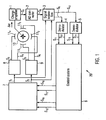
- Fig. 1 is a known embodiment of a Coriolis gyro 20 schematically indicated.
- the Coriolis gyroscope 20 has a charge amplifier 1, an analog-to-digital converter 2, a signal separation 3, demodulators 4, 5, a control system 6, a modulator 7, drivers 8, 9, a resonator 10 and an electrode system 11 with four electrodes 11 1 to 11 4 on.
- the resonator 10 can be excited to vibrate via the electrodes 11 1 to 11 4 . Furthermore, the spring constant of the resonator 10 can be adjusted or changed electrostatically via the electrodes 11 1 to 11 4 .
- the movement of the resonator 10 is detected by measuring a charge shift ⁇ q on an electrode ("movable center electrode") mounted on the resonator 10, which is caused by the movement of the resonator 10 within the electrostatic field generated by the electrodes 11 1 to 11 4 , A signal S 7 proportional to the charge shift is output by the charge amplifier 1 to the analog-to-digital converter 2 and converted by the latter into a corresponding digital signal S 8 , which is supplied to the signal separation 3.
- a gyroscopic sensor for measuring rotations about a Z axis.
- This includes a substrate, first and second mass, a coupling system interconnecting the first and second masses, a connection system connecting the first and second masses to the substrate, and a drive system including the first and second ones Mass oscillates in antiphase along a drive axle.
- the object underlying the invention is to provide a microelectromechanical sensor, for example a capacitive sensor or a piezoelectric sensor, which has the widest possible functionality despite a small number of sensor electrodes.
- the invention provides a microelectromechanical sensor according to claim 1 ready. Furthermore, the invention provides an operating method for a microelectromechanical sensor according to claim 11. Preferred embodiments or further developments of the inventive concept can be found in the subclaims.
- Electrodes signals for each arbitrary electrode arrangement can be matched to one another such that the force application, the spring constant and the readout factor of the movable electrode can be set / changed independently of one another to specific desired values, thus ensuring maximum flexibility of the operating method given the microelectromechanical sensor.
- Any electrode arrangement in this context means any spatial arrangement of at least three electrodes.
- the mass system (which is also referred to below as the "resonator") of the microelectromechanical sensor can be designed to be very different.
- the mass system which is also referred to below as the "resonator”
- the senor according to the invention is provided with a charge transfer unit which detects charge displacements occurring on the movable electrode, wherein the instantaneous movement of the movable electrode can be determined by means of an evaluation unit based on the detected charge transfer.
- the electrode signal generating unit generates each electrode signal in response to the force, the spring constant and the Auslesepanelsignals such that the detected on the movable electrode charge shift only charge shift portions which is due to the movement of the movable electrode and the value of the read-out factor, the read-out factor is to be interpreted as an amplification factor for reading out the movement of the movable electrode.
- the electrode arrangement can consist of an even or odd number of electrodes. Furthermore, the dimensions or configurations of the individual electrodes can differ from each other.
- the electrode assembly includes four (preferably identical) electrodes which may, for example, be grouped into two electrode pairs, the electrodes being axisymmetric with respect to a first axis separating the two electrode pairs and axisymmetric with respect to a second axis connecting the electrodes respective electrode pairs separated from each other, are configured.
- the movable electrode is designed point-symmetrically with respect to the point of intersection of the two axes of symmetry.
- the movable electrode in an embodiment in which the movable electrode is formed as part of a resonator, the movable electrode can be made to vibrate and the sensor can be used, for example, as a Coriolis gyroscope.
- both movable electrodes can be read out separately by appropriate selection of the two read-out factors and independently set the movements (influenced by the force application) and spring constants.
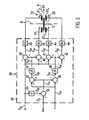
- Fig. 2 shows a section of a preferred embodiment of the microelectromechanical sensor according to the invention 30.
- the in Fig. 2 The detail shown can be roughly with the "ensemble" modulator 7, driver 8, 9, resonator 10 and electrode assembly 11 1 to 11 4 and in Fig. 1 be compared.
- FIG. 1 shows a spaced-apart electrode arrangement 31, which comprises a first to a fourth electrode 31 1 to 31 4 , as opposed to a movable electrode 29, which may be part of a resonator (not shown), for example.
- the first and third electrodes 31 1 , 31 3 and the second and fourth electrodes 31 2 , 31 4 each form a pair of electrodes.
- the electrodes of a pair of electrodes are arranged axially symmetrically with respect to an axis A. Furthermore, the electrode pairs are separated from each other by an axis A perpendicular to axis A axisymmetric.
- the mobile one Electrode 29 is, for example, point-symmetrical with respect to an intersection point S of the two symmetry axes A. B, as in FIG Fig. 2 shown.
- an electrode signal generation unit 32 which can supply a force application signal S 20 (also referred to as “f"), a spring constant signal S 21 (also referred to as “ ⁇ ”) and a readout factor signal S 22 (also referred to as “m”) are.
- the read-out factor signal S 22 is squared in a squaring unit 33 and the signal S 23 thus obtained is supplied with a negative sign to a first adder 34, where it is added to the spring constant signal S 21 .
- the output signal S 24 of the adder 34 is fed to a second and a third adder 35, 36. In the second adder 35, the signal S 24 is added to the signal S 20 , whereas in the third adder 36, the signal S 20 is added to the signal S 24 with a negative sign.
- the output signals S 25 , S 26 of the adder stages 35, 36 are fed to root units 37, 38, which each determine the root from one of the signals S 25 , S 26 .
- the output signals S 27 , S 28 of the root units 37, 38 are supplied to a fourth to seventh adder 39 to 42, by each of the signals S 27 , S 28 are added once to the signal S 22 and subtracted from this signal.
- Corresponding output signals S 29 to S 32 are supplied to digital-to-analog converters 43 to 46, which convert the (previously digital) signals into analog signals u o1 , u o2 , u u1 , u u2 and apply them to the corresponding electrodes 31 1 to 31 4 .
- the electrode signals u o1 .u o2 represent those electrode signals which are applied to the electrodes 31 1 located above the axis A. 31 2 abut , and u u1 , u u2, the electrode signals are applied to the located below the axis A electrodes 31 3 , 31 4 .
- the connection of the mobile Electrode 29 is at virtual mass, measured is the charge flowing out of the movable electrode 29.
- Fig. 3 It is shown how two movable, electrically connected electrodes 29, 50 can be combined in a multiplexing process.
- the control signals m, and m 2 connected as in Fig. 3b shown alternately make a respective movable electrode 29, 50 for the charge amplifier 70 visible. Regardless of the impressions f 1 and f 2 and the votes ⁇ 1 and ⁇ 2 can be selected.
- Fig. 3 shows an electrode assembly 51 spaced apart from a second movable electrode 50 electrically connected to the at least one movable electrode 29 and consisting of first to fourth electrodes 51 1 to 51 4 .
- the first and third electrodes 51 1 , 51 9 and the second and fourth electrodes 51 2 , 51 4 each form a pair of electrodes.
- the electrodes of a pair of electrodes are arranged axially symmetrically with respect to an axis A 2 . Furthermore, the electrode pairs are separated by a perpendicular to the axis A 2 D 2 axis axisymmetrical from each other.
- a second electrode signal generation unit 52 which generates a second force signal S 20 (also referred to as “f 2 "), a second spring rate signal S 21 (also referred to as “ ⁇ 2 ”) and a second readout factor signal S 22 (Also referred to as “m 2 ”) can be fed.
- the second readout factor signal S 22 is squared in a second squaring unit 53 and the signal thus obtained S 23 supplied with a negative sign of an eighth adder 54, where this on the second Federkonstantensignal S 21 is added.
- the eighth adder 54 is supplied to ninth and tenth adders 55, 56.
- the signal becomes S 24 on the signal S 20 whereas in the tenth adder 56 the signal S 20 with a negative sign on the signal S 24 is added.
- S 26 the adder stages 55, 56 are supplied to second root units 57, 58, each of which is one of the signals S 25 , S 26 determine the root.
- S 28 The second root units 57, 58 are supplied to eleventh to fourteenth adders 59 to 62, through which each of the signals P 27, S 28 once each on the signal S 22 be added and subtracted from this signal.
- Corresponding output signals P 29 to S 32 be second digital-to-analog converters 63 bis 66 supplied to the (previously digital) signals in analog signals u o1 . u o2 . u u1 , u u2 and apply to the corresponding electrodes 51 1 to 51 4 .
- the electrode signals u o1 , u o2 those electrode signals which are applied to the above the axis A 2 located electrodes 51 1, 51 2 , and u u1 .
- u u2 the electrode signals are applied to the located below the axis A 2 electrodes 51 3 , 51 4 .
- the force is composed of a part independent of x and a part proportional to x, which corresponds to a spring constant.
- the part independent of x is too U 1 2 - U 2 2 proportional
- the spring constant is too U 1 2 + U 2 2 proportional.
- the path-independent term is proportional to U O ⁇ 1 2 + U O ⁇ 2 2 - U u ⁇ 1 2 - U u ⁇ 2 2 and the spring constant too U O ⁇ 1 2 + U O ⁇ 2 2 + U u ⁇ 1 2 + U u ⁇ 2 2
- the path-independent part is suitable for impressing a desired force (return, Torquer), and the spring constant allows in conjunction with a spring-mass system, the vote of the same to a desired resonant frequency.
- the first term produces x independent talk (and is usually unwanted), while the second part is proportional to x, and therefore is suitable for reading the deflection x.
- a "down-mixing detector” can be realized if, for example, the readout factor is configured as a sinusoidal carrier with the same frequency as the electrode oscillation. The oscillation is down-converted to the frequency 0, which leads to a phase-sensitive demodulator.
- the read-out functions of several oscillators, the movable electrodes of which are electrically connected can be read out by the time-division multiplex method by setting only the read-out factor of a vibrator to a value other than zero, and thus only one oscillator movement in time sequence common charge amplifier is detected.
- microelectromechanical sensors with divided electrodes
- the inventive method allows, in systems with a plurality of electrically coupled movable electrodes exciting force. resonance tuning and readout factor set separately from each other.
- a read-out operation in multiplex mode is completely independent of excitation processes (generation of the excitation oscillation) and tuning processes (eg frequency tuning of excitation oscillation to read oscillation in order to obtain a double-resonant resonator).
Landscapes
- Engineering & Computer Science (AREA)
- Physics & Mathematics (AREA)
- General Physics & Mathematics (AREA)
- Radar, Positioning & Navigation (AREA)
- Remote Sensing (AREA)
- Signal Processing (AREA)
- Computer Hardware Design (AREA)
- Microelectronics & Electronic Packaging (AREA)
- Gyroscopes (AREA)
- Micromachines (AREA)
- Measurement Of Length, Angles, Or The Like Using Electric Or Magnetic Means (AREA)
- Investigating Or Analyzing Materials By The Use Of Fluid Adsorption Or Reactions (AREA)
- Pressure Sensors (AREA)
Claims (11)
- Capteur microélectromécanique (30), avec :- au moins une électrode mobile (29),- un dispositif à électrodes (311-314), espacé de l'électrode mobile (29), avec au moins quatre électrodes qui sont aptes à être commandées séparément et auxquelles des signaux d'électrodes correspondants (uo1, uo2, uu1, uu2) peuvent être appliqués, étant précisé qu'à l'aide des signaux d'électrodes, l'application de force, la constante de rappel et le facteur de sélection du résonateur peuvent être réglés/modifiés par voie électrostatique,- une unité génératrice de signaux d'électrodes (32) qui est reliée au dispositif à électrodes (311-314) et à laquelle peuvent être transmis un signal d'application de force (f), un signal de constante de rappel (Δω) et un signal de facteur de sélection (m) grâce auxquels les réglages/modifications à effectuer en matière d'application de force, de constante de rappel et de facteur de sélection - de l'électrode mobile (29) sont fixés,- étant précisé que l'unité génératrice de signaux d'électrodes (32) est conçue pour générer chaque signal d'électrode (uo1, uo2, uu1, uu2) en fonction des signaux d'application de force, de constante de rappel et de facteur de sélection (f, Δω, m) et pour accorder les signaux d'électrodes (uo1, uo2, uu1, uu2) de telle sorte que l'application de force, la constante de rappel et le facteur de sélection du résonateur puissent être réglés/modifiés indépendamment les uns des autres sur des valeurs théoriques.
- Capteur microélectromécanique (30) selon la revendication 1, caractérisé par- une unité de transfert de charge qui est conçue pour détecter les transferts de charge apparaissant sur l'électrode mobile (29), et- une unité d'analyse qui est conçue pour rechercher, sur la base du transfert de charge détecté, le déplacement momentané de l'électrode mobile (29).
- Capteur microélectromécanique (30) selon la revendication 2, caractérisé en ce que l'unité génératrice de signaux d'électrodes est conçue pour générer chaque signal d'électrode (uo1, uo2, uu1, uu2) en fonction des signaux d'application de force, de constante de rappel et de facteur de sélection (f, Δω, m) de telle sorte que le transfert de charge ne contienne que des parts de transfert de charge qui proviennent du déplacement de l'électrode mobile (29) et de la valeur du facteur de sélection.
- Capteur microélectromécanique (30) selon l'une des revendications précédentes, caractérisé en ce que le dispositif à électrodes (311-314) contient quatre électrodes.
- Capteur microélectromécanique (30) selon la revendication 4, caractérisé en ce que les quatre électrodes (311-314) sont groupées en deux paires d'électrodes (311, 313 ; 312, 314), étant précisé que les électrodes sont conçues avec une symétrie axiale par rapport à un premier axe (B) qui sépare les deux paires d'électrodes (311, 313 ; 312, 314) , et avec une symétrie axiale par rapport à un second axe (A) qui sépare les électrodes des paires d'électrodes (311, 313 ; 312, 314).
- Capteur microélectromécanique (30) selon la revendication 5, caractérisé en ce que l'électrode mobile (29) est conçue avec une symétrie ponctuelle par rapport à l'intersection (S) des deux axes de symétrie (A, B).
- Capteur microélectromécanique (30) selon la revendication 5, caractérisé en ce que les signaux d'électrodes (uo1, uo2, uu1, uu2) sont définis par les équations suivantes :


étant précisé que (Δω) représente la valeur du signal de constante de rappel, (m) la valeur du signal de facteur de sélection, et (f) la valeur du signal d'application de force, (uo1, uo2) les valeurs des signaux d'électrodes qui sont situées au-dessus du second axe, et (uu1, uu2) les valeurs des signaux d'électrodes qui sont situées au-dessus du second axe. - Capteur microélectromécanique (30) selon la revendication 7, caractérisé en ce qu'on a la relation suivante :

- Capteur microélectromécanique (30) selon l'une des revendications 1 à 8, caractérisé en ce que l'électrode mobile (29) est conçue comme une partie d'un résonateur.
- Capteur microélectromécanique (30) selon l'une des revendications 1 à 9, caractérisé par une seconde électrode mobile (50), qui est reliée électriquement à ladite électrode mobile (29),- un second dispositif à électrodes (511-514), espacé de la seconde électrode mobile (50), avec plusieurs autres électrodes qui sont aptes à être commandées séparément et auxquelles des signaux d'électrodes correspondants (
u o1 ,uo2 ,u u1 ,u u2 ) peuvent être appliqués, étant précisé qu'à l'aide des signaux d'électrodes, l'application de force, la constante de rappel et le facteur de sélection de la seconde électrode mobile (50) peuvent être réglés/modifiés par voie électrostatique,- une seconde unité génératrice de signaux d'électrodes (52) qui est reliée au second dispositif à électrodes (511-514) et à laquelle peuvent être transmis un second signal d'application de force (f2) , un second signal de constante de rappel (Δω2) et un second signal de facteur de sélection (m2) grâce auxquels les réglages/modifications à effectuer en matière d'application de force, de constante de rappel et de facteur de sélection du résonateur sont fixés,- étant précisé que la seconde unité génératrice de signaux d'électrodes (52) est conçue pour générer chaque signal d'électrode (u o1 ,u o2 ,u u1 ,u u2 ) en fonction des seconds signaux d'application de force, de constante de rappel et de facteur de sélection (f2, Δω2, m2) et pour accorder les signaux d'électrodes (uo1, uo2, uu1, uu2) de telle sorte que la seconde application de force, la seconde constante de rappel et le second facteur de sélection de la seconde électrode mobile (50) puissent être réglés/modifiés indépendamment les uns des autres et indépendamment de l'application de force, de la constante de rappel et du facteur de sélection de ladite électrode mobile (29) sur des valeurs théoriques définies. - Procédé de fonctionnement pour un capteur microélectromécanique (30) qui comporte au moins une électrode mobile (29) et un dispositif à électrodes (311-314), espacé de l'électrode mobile (29), avec au moins quatre électrodes qui sont aptes à être commandées séparément et auxquelles des signaux d'électrodes (uo1, uo2, uu1, uu2) peuvent être appliqués, avec les étapes suivantes :- production des signaux d'électrodes (uo1, uo2, uu1, uu2) en fonction d'un signal d'application de force (f), d'un signal de constante de rappel (Δω) et d'un signal de facteur de sélection (m) grâce auxquels les réglages/modifications à effectuer en matière d'application de force, de constante de rappel et de facteur de sélection de l'électrode mobile (29) sont fixés,- application des signaux d'électrodes (uo1, uo2, uu1, uu2) aux électrodes correspondantes, afin de régler/modifier par voie électrostatique l'application de force, la constante de rappel et le facteur de sélection de l'électrode mobile (29),- étant précisé que chaque signal d'électrode (uo1, uo2, uu1, uu2) est généré en fonction du signal d'application de force (f), de constante de rappel (Δω) et de sélection (m) et que les signaux d'électrodes sont accordés de telle sorte que l'application de force, la constante de rappel et le facteur de sélection de l'électrode mobile (29) soient réglés/modifiés indépendamment les uns des autres sur des valeurs théoriques définies.
Applications Claiming Priority (2)
| Application Number | Priority Date | Filing Date | Title |
|---|---|---|---|
| DE102006043412A DE102006043412A1 (de) | 2006-09-15 | 2006-09-15 | Mikroelektromechanischer Sensor sowie Betriebsverfahren für einen mikroelektromechanischen Sensor |
| PCT/EP2007/007028 WO2008031480A1 (fr) | 2006-09-15 | 2007-08-08 | Capteur microélectromécanique et procédé de fonctionnement pour un capteur microélectromécanique |
Publications (2)
| Publication Number | Publication Date |
|---|---|
| EP2062009A1 EP2062009A1 (fr) | 2009-05-27 |
| EP2062009B1 true EP2062009B1 (fr) | 2012-01-11 |
Family
ID=38622548
Family Applications (1)
| Application Number | Title | Priority Date | Filing Date |
|---|---|---|---|
| EP07786628A Active EP2062009B1 (fr) | 2006-09-15 | 2007-08-08 | Capteur microelectromecanique et procede de fonctionnement pour un capteur microelectromecanique |
Country Status (13)
| Country | Link |
|---|---|
| US (1) | US8424382B2 (fr) |
| EP (1) | EP2062009B1 (fr) |
| JP (1) | JP5259598B2 (fr) |
| KR (1) | KR101093883B1 (fr) |
| CN (1) | CN101517359B (fr) |
| AT (1) | ATE541186T1 (fr) |
| AU (1) | AU2007296984B2 (fr) |
| CA (1) | CA2661525C (fr) |
| DE (1) | DE102006043412A1 (fr) |
| NO (1) | NO340343B1 (fr) |
| RU (1) | RU2419768C2 (fr) |
| WO (1) | WO2008031480A1 (fr) |
| ZA (1) | ZA200901501B (fr) |
Families Citing this family (8)
| Publication number | Priority date | Publication date | Assignee | Title |
|---|---|---|---|---|
| DE102009019318A1 (de) * | 2009-04-30 | 2011-03-24 | Continental Teves Ag & Co. Ohg | Verfahren zum präzisen Messbetrieb eines mikromechanischen Drehratensensors |
| US9535084B2 (en) | 2010-03-17 | 2017-01-03 | Continental Teves Ag & Co. Ohg | Method for the decoupled control of the quadrature and the resonance frequency of a micro-mechanical rotation rate sensor by means of sigma-delta-modulation |
| KR101889991B1 (ko) * | 2010-03-17 | 2018-08-20 | 콘티넨탈 테베스 아게 운트 코. 오하게 | 미소-기계적 자이로스코프의 쿼드러쳐 및 공진 주파수의 디커플링된 제어를 위한 방법 |
| CN103003704B (zh) * | 2011-05-23 | 2016-05-04 | 深迪半导体(上海)有限公司 | 感测旋转及加速度两者的微机电系统装置 |
| DE102014003640A1 (de) * | 2014-03-14 | 2015-09-17 | Northrop Grumman Litef Gmbh | Verfahren zum optimieren der einschaltzeit eines corioliskreisels sowie dafür geeigneter corioliskreisel |
| DE102014004858A1 (de) | 2014-04-03 | 2014-11-06 | Daimler Ag | Befestigungsanordnung wenigstens eines Lagerelements an einem Kurbelgehäuse einer Hubkolben-Verbrennungskraftmaschine |
| EP3154986A1 (fr) * | 2014-06-16 | 2017-04-19 | Allinky Biopharma | Inhibiteurs de p38 et de jnk mapk pour le traitement et la prophylaxie des maladies dégénératives du système nerveux |
| KR102286261B1 (ko) * | 2020-09-14 | 2021-08-04 | 이재철 | 락인 제로 링 레이저 자이로스코프 시스템 및 그 구동 방법 |
Family Cites Families (13)
| Publication number | Priority date | Publication date | Assignee | Title |
|---|---|---|---|---|
| US5497660A (en) * | 1994-05-31 | 1996-03-12 | Litton Systems, Inc. | Digital force balanced instrument |
| US5992233A (en) * | 1996-05-31 | 1999-11-30 | The Regents Of The University Of California | Micromachined Z-axis vibratory rate gyroscope |
| US6250156B1 (en) | 1996-05-31 | 2001-06-26 | The Regents Of The University Of California | Dual-mass micromachined vibratory rate gyroscope |
| JP3407689B2 (ja) * | 1999-04-22 | 2003-05-19 | 株式会社村田製作所 | 振動ジャイロ |
| CN2397473Y (zh) * | 1999-09-29 | 2000-09-20 | 中国科学院上海冶金研究所 | 栅型结构电容式微机械谐振陀螺 |
| RU2249299C2 (ru) * | 1999-11-02 | 2005-03-27 | Ета Са Фабрик Д`Эбош | Система отсчета времени, содержащая интегрированный микромеханический кольцевой резонатор |
| US20030033850A1 (en) * | 2001-08-09 | 2003-02-20 | Challoner A. Dorian | Cloverleaf microgyroscope with electrostatic alignment and tuning |
| US20040027033A1 (en) * | 2002-08-08 | 2004-02-12 | Schiller Peter J. | Solid-state acceleration sensor device and method |
| DE10248733B4 (de) * | 2002-10-18 | 2004-10-28 | Litef Gmbh | Verfahren zur elektronischen Abstimmung der Ausleseschwingungsfrequenz eines Corioliskreisels |
| US6934660B2 (en) * | 2003-02-20 | 2005-08-23 | The Regents Of The University Of California | Multi stage control architecture for error suppression in micromachined gyroscopes |
| DE10320675B4 (de) | 2003-05-08 | 2006-03-16 | Litef Gmbh | Betriebsverfahren für einen Corioliskreisel und dafür geeignete Auswerte-/Regelelektronik |
| DE10360963B4 (de) * | 2003-12-23 | 2007-05-16 | Litef Gmbh | Verfahren zur Messung von Drehraten/Beschleunigungen unter Verwendung eines Drehraten-Corioliskreisels sowie dafür geeigneter Corioliskreisel |
| DE102004056699A1 (de) | 2004-11-24 | 2006-06-01 | Litef Gmbh | Verfahren zur Steuerung/Regelung einer physikalischen Größe eines dynamischen Systems, insbesondere eines mikromechanischen Sensors |
-
2006
- 2006-09-15 DE DE102006043412A patent/DE102006043412A1/de not_active Ceased
-
2007
- 2007-08-08 EP EP07786628A patent/EP2062009B1/fr active Active
- 2007-08-08 WO PCT/EP2007/007028 patent/WO2008031480A1/fr active Application Filing
- 2007-08-08 AU AU2007296984A patent/AU2007296984B2/en not_active Ceased
- 2007-08-08 US US12/310,572 patent/US8424382B2/en not_active Expired - Fee Related
- 2007-08-08 RU RU2009102521/28A patent/RU2419768C2/ru not_active IP Right Cessation
- 2007-08-08 JP JP2009527708A patent/JP5259598B2/ja not_active Expired - Fee Related
- 2007-08-08 CA CA2661525A patent/CA2661525C/fr not_active Expired - Fee Related
- 2007-08-08 AT AT07786628T patent/ATE541186T1/de active
- 2007-08-08 KR KR1020097004067A patent/KR101093883B1/ko not_active IP Right Cessation
- 2007-08-08 CN CN2007800343724A patent/CN101517359B/zh active Active
-
2009
- 2009-02-23 NO NO20090842A patent/NO340343B1/no unknown
- 2009-03-03 ZA ZA2009/01501A patent/ZA200901501B/en unknown
Also Published As
| Publication number | Publication date |
|---|---|
| KR101093883B1 (ko) | 2011-12-13 |
| WO2008031480A9 (fr) | 2009-03-05 |
| ATE541186T1 (de) | 2012-01-15 |
| AU2007296984B2 (en) | 2010-09-30 |
| US8424382B2 (en) | 2013-04-23 |
| US20100186503A1 (en) | 2010-07-29 |
| NO20090842L (no) | 2009-06-10 |
| JP2010502998A (ja) | 2010-01-28 |
| JP5259598B2 (ja) | 2013-08-07 |
| CN101517359B (zh) | 2011-07-13 |
| WO2008031480A1 (fr) | 2008-03-20 |
| AU2007296984A1 (en) | 2008-03-20 |
| CA2661525C (fr) | 2013-03-26 |
| NO340343B1 (no) | 2017-04-03 |
| KR20090035616A (ko) | 2009-04-09 |
| EP2062009A1 (fr) | 2009-05-27 |
| DE102006043412A1 (de) | 2008-03-27 |
| RU2009102521A (ru) | 2010-10-20 |
| RU2419768C2 (ru) | 2011-05-27 |
| CA2661525A1 (fr) | 2008-03-20 |
| ZA200901501B (en) | 2010-02-24 |
| CN101517359A (zh) | 2009-08-26 |
Similar Documents
| Publication | Publication Date | Title |
|---|---|---|
| EP2062009B1 (fr) | Capteur microelectromecanique et procede de fonctionnement pour un capteur microelectromecanique | |
| EP2162702B1 (fr) | Gyroscope coriolis | |
| DE69831143T2 (de) | Stimmgabelkreisel mit spaltelekrode | |
| EP2160566B1 (fr) | Capteur de vitesse de rotation | |
| EP2547984B1 (fr) | Procédé de régulation découplée de la quadrature et de la fréquence de résonance d'un gyroscope micromécanique | |
| DE102009000743B4 (de) | Vibrationskompensation für Drehratensensoren | |
| EP3153817B1 (fr) | Circuit électronique et procédé de correction numérique d'effets de modulation pour des modulateurs sigma-delta électromécaniques | |
| DE69822756T2 (de) | Mikromechanischer Schwingkreisel | |
| DE102012207937A1 (de) | Drehratensensor | |
| DE102010061755A1 (de) | Drehratensensor und Verfahren zum Betrieb eines Drehratensensors | |
| WO2008040616A1 (fr) | Dispositif pour mesurer une vitesse de rotation au moyen d'un capteur vibrant | |
| DE102010006584A1 (de) | Corioliskreisel mit Korrektureinheiten und Verfahren zur Reduktion des Quadraturbias | |
| DE10195200B4 (de) | Mikro-Gyroskop vom Schwingungstyp | |
| DE10360963A1 (de) | Verfahren zur Messung von Drehraten/Beschleunigungen unter Verwendung eines Drehraten-Corioliskreisels sowie dafür geeigneter Corioliskreisel | |
| DE102011005745A1 (de) | Verfahren zur entkoppelten Regelung der Quadratur und der Resonazfrequenz eines mikromechanischen Drehratensensors mittels Sigma-Delta-Modulation | |
| DE10230528B4 (de) | Verbesserungen in bzw. bezüglich eines Systems der Beseitigung der Abweichung für ein Schwinggyroskop | |
| EP1472506A1 (fr) | Capteur de vitesse de rotation micromecanique | |
| DE102021200483A1 (de) | Dreiachsiger Drehratensensor mit einem Substrat und einem Doppelrotor | |
| WO2002016871A1 (fr) | Capteur de vitesse de rotation et systeme de capteur de vitesse de rotation | |
| DE102017215503A1 (de) | Mikromechanische Drehraten-Sensoranordnung und entsprechendes Herstellungsverfahren | |
| EP2154538B1 (fr) | Capteur d'accélération et procédé pour saisir une accélération | |
| DE4430439C2 (de) | Sensoreinheit mit mindestens einem Drehratensensor und Verfahren zu seiner Herstellung | |
| DE102019008491A1 (de) | Capteur inertiel amélioré | |
| EP2153170A1 (fr) | Capteur de vitesse de rotation | |
| EP1910776A1 (fr) | Capteur de vitesse de rotation |
Legal Events
| Date | Code | Title | Description |
|---|---|---|---|
| PUAI | Public reference made under article 153(3) epc to a published international application that has entered the european phase |
Free format text: ORIGINAL CODE: 0009012 |
|
| 17P | Request for examination filed |
Effective date: 20090217 |
|
| AK | Designated contracting states |
Kind code of ref document: A1 Designated state(s): AT BE BG CH CY CZ DE DK EE ES FI FR GB GR HU IE IS IT LI LT LU LV MC MT NL PL PT RO SE SI SK TR |
|
| AX | Request for extension of the european patent |
Extension state: AL BA HR MK RS |
|
| 17Q | First examination report despatched |
Effective date: 20100216 |
|
| GRAP | Despatch of communication of intention to grant a patent |
Free format text: ORIGINAL CODE: EPIDOSNIGR1 |
|
| DAX | Request for extension of the european patent (deleted) | ||
| GRAS | Grant fee paid |
Free format text: ORIGINAL CODE: EPIDOSNIGR3 |
|
| GRAA | (expected) grant |
Free format text: ORIGINAL CODE: 0009210 |
|
| AK | Designated contracting states |
Kind code of ref document: B1 Designated state(s): AT BE BG CH CY CZ DE DK EE ES FI FR GB GR HU IE IS IT LI LT LU LV MC MT NL PL PT RO SE SI SK TR |
|
| REG | Reference to a national code |
Ref country code: GB Ref legal event code: FG4D Free format text: NOT ENGLISH |
|
| REG | Reference to a national code |
Ref country code: CH Ref legal event code: EP |
|
| REG | Reference to a national code |
Ref country code: AT Ref legal event code: REF Ref document number: 541186 Country of ref document: AT Kind code of ref document: T Effective date: 20120115 |
|
| REG | Reference to a national code |
Ref country code: IE Ref legal event code: FG4D |
|
| REG | Reference to a national code |
Ref country code: CH Ref legal event code: NV Representative=s name: RENTSCH PARTNER AG |
|
| REG | Reference to a national code |
Ref country code: DE Ref legal event code: R096 Ref document number: 502007009071 Country of ref document: DE Effective date: 20120308 |
|
| REG | Reference to a national code |
Ref country code: SE Ref legal event code: TRGR |
|
| REG | Reference to a national code |
Ref country code: NL Ref legal event code: VDEP Effective date: 20120111 |
|
| PG25 | Lapsed in a contracting state [announced via postgrant information from national office to epo] |
Ref country code: SI Free format text: LAPSE BECAUSE OF FAILURE TO SUBMIT A TRANSLATION OF THE DESCRIPTION OR TO PAY THE FEE WITHIN THE PRESCRIBED TIME-LIMIT Effective date: 20120111 |
|
| LTIE | Lt: invalidation of european patent or patent extension |
Effective date: 20120111 |
|
| PG25 | Lapsed in a contracting state [announced via postgrant information from national office to epo] |
Ref country code: IS Free format text: LAPSE BECAUSE OF FAILURE TO SUBMIT A TRANSLATION OF THE DESCRIPTION OR TO PAY THE FEE WITHIN THE PRESCRIBED TIME-LIMIT Effective date: 20120511 Ref country code: NL Free format text: LAPSE BECAUSE OF FAILURE TO SUBMIT A TRANSLATION OF THE DESCRIPTION OR TO PAY THE FEE WITHIN THE PRESCRIBED TIME-LIMIT Effective date: 20120111 Ref country code: BG Free format text: LAPSE BECAUSE OF FAILURE TO SUBMIT A TRANSLATION OF THE DESCRIPTION OR TO PAY THE FEE WITHIN THE PRESCRIBED TIME-LIMIT Effective date: 20120411 Ref country code: LT Free format text: LAPSE BECAUSE OF FAILURE TO SUBMIT A TRANSLATION OF THE DESCRIPTION OR TO PAY THE FEE WITHIN THE PRESCRIBED TIME-LIMIT Effective date: 20120111 |
|
| PG25 | Lapsed in a contracting state [announced via postgrant information from national office to epo] |
Ref country code: GR Free format text: LAPSE BECAUSE OF FAILURE TO SUBMIT A TRANSLATION OF THE DESCRIPTION OR TO PAY THE FEE WITHIN THE PRESCRIBED TIME-LIMIT Effective date: 20120412 Ref country code: LV Free format text: LAPSE BECAUSE OF FAILURE TO SUBMIT A TRANSLATION OF THE DESCRIPTION OR TO PAY THE FEE WITHIN THE PRESCRIBED TIME-LIMIT Effective date: 20120111 Ref country code: PL Free format text: LAPSE BECAUSE OF FAILURE TO SUBMIT A TRANSLATION OF THE DESCRIPTION OR TO PAY THE FEE WITHIN THE PRESCRIBED TIME-LIMIT Effective date: 20120111 Ref country code: PT Free format text: LAPSE BECAUSE OF FAILURE TO SUBMIT A TRANSLATION OF THE DESCRIPTION OR TO PAY THE FEE WITHIN THE PRESCRIBED TIME-LIMIT Effective date: 20120511 |
|
| PG25 | Lapsed in a contracting state [announced via postgrant information from national office to epo] |
Ref country code: CY Free format text: LAPSE BECAUSE OF FAILURE TO SUBMIT A TRANSLATION OF THE DESCRIPTION OR TO PAY THE FEE WITHIN THE PRESCRIBED TIME-LIMIT Effective date: 20120111 |
|
| PG25 | Lapsed in a contracting state [announced via postgrant information from national office to epo] |
Ref country code: CZ Free format text: LAPSE BECAUSE OF FAILURE TO SUBMIT A TRANSLATION OF THE DESCRIPTION OR TO PAY THE FEE WITHIN THE PRESCRIBED TIME-LIMIT Effective date: 20120111 Ref country code: RO Free format text: LAPSE BECAUSE OF FAILURE TO SUBMIT A TRANSLATION OF THE DESCRIPTION OR TO PAY THE FEE WITHIN THE PRESCRIBED TIME-LIMIT Effective date: 20120111 Ref country code: DK Free format text: LAPSE BECAUSE OF FAILURE TO SUBMIT A TRANSLATION OF THE DESCRIPTION OR TO PAY THE FEE WITHIN THE PRESCRIBED TIME-LIMIT Effective date: 20120111 Ref country code: EE Free format text: LAPSE BECAUSE OF FAILURE TO SUBMIT A TRANSLATION OF THE DESCRIPTION OR TO PAY THE FEE WITHIN THE PRESCRIBED TIME-LIMIT Effective date: 20120111 |
|
| PLBE | No opposition filed within time limit |
Free format text: ORIGINAL CODE: 0009261 |
|
| STAA | Information on the status of an ep patent application or granted ep patent |
Free format text: STATUS: NO OPPOSITION FILED WITHIN TIME LIMIT |
|
| PG25 | Lapsed in a contracting state [announced via postgrant information from national office to epo] |
Ref country code: SK Free format text: LAPSE BECAUSE OF FAILURE TO SUBMIT A TRANSLATION OF THE DESCRIPTION OR TO PAY THE FEE WITHIN THE PRESCRIBED TIME-LIMIT Effective date: 20120111 |
|
| 26N | No opposition filed |
Effective date: 20121012 |
|
| REG | Reference to a national code |
Ref country code: DE Ref legal event code: R097 Ref document number: 502007009071 Country of ref document: DE Effective date: 20121012 |
|
| BERE | Be: lapsed |
Owner name: NORTHROP GRUMMAN LITEF G.M.B.H. Effective date: 20120831 |
|
| PG25 | Lapsed in a contracting state [announced via postgrant information from national office to epo] |
Ref country code: MC Free format text: LAPSE BECAUSE OF NON-PAYMENT OF DUE FEES Effective date: 20120831 |
|
| PG25 | Lapsed in a contracting state [announced via postgrant information from national office to epo] |
Ref country code: ES Free format text: LAPSE BECAUSE OF FAILURE TO SUBMIT A TRANSLATION OF THE DESCRIPTION OR TO PAY THE FEE WITHIN THE PRESCRIBED TIME-LIMIT Effective date: 20120422 |
|
| PG25 | Lapsed in a contracting state [announced via postgrant information from national office to epo] |
Ref country code: BE Free format text: LAPSE BECAUSE OF NON-PAYMENT OF DUE FEES Effective date: 20120831 |
|
| PG25 | Lapsed in a contracting state [announced via postgrant information from national office to epo] |
Ref country code: MT Free format text: LAPSE BECAUSE OF FAILURE TO SUBMIT A TRANSLATION OF THE DESCRIPTION OR TO PAY THE FEE WITHIN THE PRESCRIBED TIME-LIMIT Effective date: 20120111 |
|
| PG25 | Lapsed in a contracting state [announced via postgrant information from national office to epo] |
Ref country code: LU Free format text: LAPSE BECAUSE OF NON-PAYMENT OF DUE FEES Effective date: 20120808 |
|
| PG25 | Lapsed in a contracting state [announced via postgrant information from national office to epo] |
Ref country code: HU Free format text: LAPSE BECAUSE OF FAILURE TO SUBMIT A TRANSLATION OF THE DESCRIPTION OR TO PAY THE FEE WITHIN THE PRESCRIBED TIME-LIMIT Effective date: 20070808 |
|
| REG | Reference to a national code |
Ref country code: FR Ref legal event code: PLFP Year of fee payment: 10 |
|
| REG | Reference to a national code |
Ref country code: FR Ref legal event code: PLFP Year of fee payment: 11 |
|
| REG | Reference to a national code |
Ref country code: CH Ref legal event code: PCAR Free format text: NEW ADDRESS: BELLERIVESTRASSE 203 POSTFACH, 8034 ZUERICH (CH) |
|
| PGFP | Annual fee paid to national office [announced via postgrant information from national office to epo] |
Ref country code: AT Payment date: 20170821 Year of fee payment: 11 |
|
| REG | Reference to a national code |
Ref country code: FR Ref legal event code: PLFP Year of fee payment: 12 |
|
| REG | Reference to a national code |
Ref country code: AT Ref legal event code: MM01 Ref document number: 541186 Country of ref document: AT Kind code of ref document: T Effective date: 20180808 |
|
| PG25 | Lapsed in a contracting state [announced via postgrant information from national office to epo] |
Ref country code: AT Free format text: LAPSE BECAUSE OF NON-PAYMENT OF DUE FEES Effective date: 20180808 |
|
| PGFP | Annual fee paid to national office [announced via postgrant information from national office to epo] |
Ref country code: SE Payment date: 20210823 Year of fee payment: 15 |
|
| REG | Reference to a national code |
Ref country code: SE Ref legal event code: EUG |
|
| PG25 | Lapsed in a contracting state [announced via postgrant information from national office to epo] |
Ref country code: SE Free format text: LAPSE BECAUSE OF NON-PAYMENT OF DUE FEES Effective date: 20220809 |
|
| P01 | Opt-out of the competence of the unified patent court (upc) registered |
Effective date: 20230512 |
|
| PGFP | Annual fee paid to national office [announced via postgrant information from national office to epo] |
Ref country code: TR Payment date: 20230801 Year of fee payment: 17 Ref country code: IT Payment date: 20230831 Year of fee payment: 17 Ref country code: IE Payment date: 20230821 Year of fee payment: 17 Ref country code: GB Payment date: 20230824 Year of fee payment: 17 Ref country code: FI Payment date: 20230823 Year of fee payment: 17 Ref country code: CH Payment date: 20230902 Year of fee payment: 17 |
|
| PGFP | Annual fee paid to national office [announced via postgrant information from national office to epo] |
Ref country code: FR Payment date: 20230821 Year of fee payment: 17 Ref country code: DE Payment date: 20230828 Year of fee payment: 17 |