EP2061581B1 - Gas-liquid contact body and method of coating - Google Patents
Gas-liquid contact body and method of coating Download PDFInfo
- Publication number
- EP2061581B1 EP2061581B1 EP07811745.4A EP07811745A EP2061581B1 EP 2061581 B1 EP2061581 B1 EP 2061581B1 EP 07811745 A EP07811745 A EP 07811745A EP 2061581 B1 EP2061581 B1 EP 2061581B1
- Authority
- EP
- European Patent Office
- Prior art keywords
- gas
- contact body
- air inlet
- sheets
- coating
- Prior art date
- Legal status (The legal status is an assumption and is not a legal conclusion. Google has not performed a legal analysis and makes no representation as to the accuracy of the status listed.)
- Active
Links
- 239000007788 liquid Substances 0.000 title claims abstract description 25
- 239000011248 coating agent Substances 0.000 title claims description 23
- 238000000576 coating method Methods 0.000 title claims description 23
- 238000000034 method Methods 0.000 title claims description 4
- 239000000463 material Substances 0.000 claims abstract description 20
- 230000007423 decrease Effects 0.000 claims abstract description 8
- 239000007921 spray Substances 0.000 claims description 14
- 239000004033 plastic Substances 0.000 claims description 4
- 229920003023 plastic Polymers 0.000 claims description 4
- NIXOWILDQLNWCW-UHFFFAOYSA-N acrylic acid group Chemical group C(C=C)(=O)O NIXOWILDQLNWCW-UHFFFAOYSA-N 0.000 claims description 3
- 229920000126 latex Polymers 0.000 claims description 3
- 238000005507 spraying Methods 0.000 claims description 2
- XLYOFNOQVPJJNP-UHFFFAOYSA-N water Substances O XLYOFNOQVPJJNP-UHFFFAOYSA-N 0.000 description 25
- 238000001816 cooling Methods 0.000 description 16
- 239000000758 substrate Substances 0.000 description 10
- 241000195493 Cryptophyta Species 0.000 description 7
- 230000005791 algae growth Effects 0.000 description 5
- 238000010276 construction Methods 0.000 description 5
- 230000008020 evaporation Effects 0.000 description 5
- 238000001704 evaporation Methods 0.000 description 5
- 239000000428 dust Substances 0.000 description 4
- 238000011109 contamination Methods 0.000 description 3
- 239000000835 fiber Substances 0.000 description 3
- 239000002655 kraft paper Substances 0.000 description 3
- 235000015097 nutrients Nutrition 0.000 description 3
- 239000011241 protective layer Substances 0.000 description 3
- 229920000742 Cotton Polymers 0.000 description 2
- GWEVSGVZZGPLCZ-UHFFFAOYSA-N Titan oxide Chemical compound O=[Ti]=O GWEVSGVZZGPLCZ-UHFFFAOYSA-N 0.000 description 2
- 239000003619 algicide Substances 0.000 description 2
- 238000004140 cleaning Methods 0.000 description 2
- 230000008021 deposition Effects 0.000 description 2
- 239000011152 fibreglass Substances 0.000 description 2
- 239000012535 impurity Substances 0.000 description 2
- 230000035755 proliferation Effects 0.000 description 2
- 239000005995 Aluminium silicate Substances 0.000 description 1
- 229920000114 Corrugated plastic Polymers 0.000 description 1
- 230000006750 UV protection Effects 0.000 description 1
- 238000010521 absorption reaction Methods 0.000 description 1
- PNEYBMLMFCGWSK-UHFFFAOYSA-N aluminium oxide Inorganic materials [O-2].[O-2].[O-2].[Al+3].[Al+3] PNEYBMLMFCGWSK-UHFFFAOYSA-N 0.000 description 1
- 235000012211 aluminium silicate Nutrition 0.000 description 1
- 238000009395 breeding Methods 0.000 description 1
- 230000001488 breeding effect Effects 0.000 description 1
- 239000006229 carbon black Substances 0.000 description 1
- 229920001971 elastomer Polymers 0.000 description 1
- 239000002657 fibrous material Substances 0.000 description 1
- 239000011521 glass Substances 0.000 description 1
- 230000005484 gravity Effects 0.000 description 1
- 230000012010 growth Effects 0.000 description 1
- 229910052500 inorganic mineral Inorganic materials 0.000 description 1
- NLYAJNPCOHFWQQ-UHFFFAOYSA-N kaolin Chemical compound O.O.O=[Al]O[Si](=O)O[Si](=O)O[Al]=O NLYAJNPCOHFWQQ-UHFFFAOYSA-N 0.000 description 1
- 239000004816 latex Substances 0.000 description 1
- 239000011707 mineral Substances 0.000 description 1
- 239000000203 mixture Substances 0.000 description 1
- 238000012986 modification Methods 0.000 description 1
- 230000004048 modification Effects 0.000 description 1
- 239000002985 plastic film Substances 0.000 description 1
- 229920001296 polysiloxane Polymers 0.000 description 1
- 239000011148 porous material Substances 0.000 description 1
- 230000004224 protection Effects 0.000 description 1
- 239000011253 protective coating Substances 0.000 description 1
- 230000001681 protective effect Effects 0.000 description 1
- 229920005989 resin Polymers 0.000 description 1
- 239000011347 resin Substances 0.000 description 1
- 239000007787 solid Substances 0.000 description 1
- 239000010409 thin film Substances 0.000 description 1
- 239000004408 titanium dioxide Substances 0.000 description 1
Images


Classifications
-
- F—MECHANICAL ENGINEERING; LIGHTING; HEATING; WEAPONS; BLASTING
- F28—HEAT EXCHANGE IN GENERAL
- F28C—HEAT-EXCHANGE APPARATUS, NOT PROVIDED FOR IN ANOTHER SUBCLASS, IN WHICH THE HEAT-EXCHANGE MEDIA COME INTO DIRECT CONTACT WITHOUT CHEMICAL INTERACTION
- F28C1/00—Direct-contact trickle coolers, e.g. cooling towers
- F28C1/04—Direct-contact trickle coolers, e.g. cooling towers with cross-current only
-
- B—PERFORMING OPERATIONS; TRANSPORTING
- B01—PHYSICAL OR CHEMICAL PROCESSES OR APPARATUS IN GENERAL
- B01F—MIXING, e.g. DISSOLVING, EMULSIFYING OR DISPERSING
- B01F23/00—Mixing according to the phases to be mixed, e.g. dispersing or emulsifying
- B01F23/20—Mixing gases with liquids
-
- F—MECHANICAL ENGINEERING; LIGHTING; HEATING; WEAPONS; BLASTING
- F28—HEAT EXCHANGE IN GENERAL
- F28F—DETAILS OF HEAT-EXCHANGE AND HEAT-TRANSFER APPARATUS, OF GENERAL APPLICATION
- F28F25/00—Component parts of trickle coolers
- F28F25/02—Component parts of trickle coolers for distributing, circulating, and accumulating liquid
- F28F25/08—Splashing boards or grids, e.g. for converting liquid sprays into liquid films; Elements or beds for increasing the area of the contact surface
- F28F25/087—Vertical or inclined sheets; Supports or spacers
-
- F—MECHANICAL ENGINEERING; LIGHTING; HEATING; WEAPONS; BLASTING
- F28—HEAT EXCHANGE IN GENERAL
- F28F—DETAILS OF HEAT-EXCHANGE AND HEAT-TRANSFER APPARATUS, OF GENERAL APPLICATION
- F28F2245/00—Coatings; Surface treatments
- F28F2245/02—Coatings; Surface treatments hydrophilic
-
- F—MECHANICAL ENGINEERING; LIGHTING; HEATING; WEAPONS; BLASTING
- F28—HEAT EXCHANGE IN GENERAL
- F28F—DETAILS OF HEAT-EXCHANGE AND HEAT-TRANSFER APPARATUS, OF GENERAL APPLICATION
- F28F2245/00—Coatings; Surface treatments
- F28F2245/08—Coatings; Surface treatments self-cleaning
-
- F—MECHANICAL ENGINEERING; LIGHTING; HEATING; WEAPONS; BLASTING
- F28—HEAT EXCHANGE IN GENERAL
- F28F—DETAILS OF HEAT-EXCHANGE AND HEAT-TRANSFER APPARATUS, OF GENERAL APPLICATION
- F28F2265/00—Safety or protection arrangements; Arrangements for preventing malfunction
- F28F2265/20—Safety or protection arrangements; Arrangements for preventing malfunction for preventing development of microorganisms
-
- Y—GENERAL TAGGING OF NEW TECHNOLOGICAL DEVELOPMENTS; GENERAL TAGGING OF CROSS-SECTIONAL TECHNOLOGIES SPANNING OVER SEVERAL SECTIONS OF THE IPC; TECHNICAL SUBJECTS COVERED BY FORMER USPC CROSS-REFERENCE ART COLLECTIONS [XRACs] AND DIGESTS
- Y02—TECHNOLOGIES OR APPLICATIONS FOR MITIGATION OR ADAPTATION AGAINST CLIMATE CHANGE
- Y02B—CLIMATE CHANGE MITIGATION TECHNOLOGIES RELATED TO BUILDINGS, e.g. HOUSING, HOUSE APPLIANCES OR RELATED END-USER APPLICATIONS
- Y02B30/00—Energy efficient heating, ventilation or air conditioning [HVAC]
- Y02B30/70—Efficient control or regulation technologies, e.g. for control of refrigerant flow, motor or heating
Definitions
- the present invention relates to contact bodies for evaporative cooling apparatus and the like and a method of forming the coating.
- Cooling towers and evaporative coolers or the like remove heat from water by causing water to gravitate through a fill assembly in heat exchange relationship with currents of air. As a result the temperature of the water is lowered by the surface evaporation of the water before being returned to the equipment employing the water for various thermal interchange functions.
- contact bodies for use in these apparatus from a plurality of sheets of corrugated materials defining a plurality of channels or ducts in the contact body through which gas and liquid are passed.
- One such well known contact body is disclosed for example in U.S. Pat. No. 3,500,615 .
- Such contact bodies are formed from a range of materials including Kraft paper, fiberglass, plastic, and other materials often porous materials as well as impregnated materials as shown for example in U.S. Pat. No. 3,862,280 .
- Gas contact bodies of this type have distinct advantages in cooling towers and evaporative cooling apparatus. Among the few disadvantages are that such contact bodies also serve as excellent air filters and breeding grounds for algae. This is particularly true along the air inlet side of the contact body which encounters the most dirt and atmospheric impurities, and is also exposed to sunlight. Accordingly, this portion of the contact body is subject to contamination and clogging as a result of dust and dirt entering the contact body.
- algae will form at the interface between the wetted contact media and the sunlight, typically on the inlet side by also possibly on the outlet side of the contact body. Given the construction of the typical evaporative cooling apparatus, it is the first one-quarter to one inch of the channels of the media which will be exposed to sunlight and subject to the proliferation of algae in the presence of the light, nutrients and moisture.
- U.S. Patent No. 5,248,454 discloses a gas - liquid contact body formed of a plurality of facially opposed corrugated-sheets with the corrugation in alternate sheets being disposed in parallel to form a plurality of criss-crossing channels for gas and liquid.
- the air inlet side of the contact body has an air inlet portion coated with a water impermeable hydrophilic material containing an algaecide. That system does an excellent job of preventing algae growth and damage to the leading edge of the cooling media.
- the coating which is usually formed of a water impervious material, creates an abrupt interface at the inner edge of the coating with the porous sheet.
- evaporative cooling pads are engineered with porous substrates that hold and transfer water the surface is 100% available for evaporation and the substrate evens out the distribution of water over the surface of the evaporative medium.
- the prior art solution of coating the edges of the substrate inhibits evaporation at the edge of the cooling pad in the area where the air entering is hottest and driest.
- Another object of the present invention is to provide a contact body which has a self-cleaning air inlet and/or air outlet edge portion.
- Another object of the present invention is to provide a contact body which has an edge portion which will resist the deposition and proliferation of algae.
- a gas-liquid contact body for use in a gas-liquid contact apparatus, said contact body comprising a plurality of facially opposed corrugated sheets with the corrugations in alternate sheets being disposed in parallel to form a plurality of criss-crossing channels for gas and liquid, said contact body having an air inlet side including an air inlet edge and an inlet edge portion downstream of said edge, said air inlet edge portion being coated with a water-impermeable hydrophilic material whose density of coverage decreases from a maximum of said air inlet edge downstream, within said air inlet portion to expose progressively increasing areas of said sheets to the air.
- the sheets of the contact body may define a plurality of intersecting and intercommunicating passages allowing the passage of gas and liquid therethrough.
- the corrugations in each of the sheets may extend at an angle to the main direction of flow of gas through the contact body, with the corrugations and alternate strips being disposed at an angle to the corrugations in the strips disposed between the alternate strips.
- the gas inlet edge of the contact body is coated with a water impermeable hydrophilic material containing an algicide of varying density from the edge of the sheets inwardly.
- the corrugations may be coated so that the surfaces of the corrugations facing the sun are more densely coated and those facing away from the sun when installed are more lightly coated. The coating's coverage of these surfaces decreases inwardly from the edge of the sheets. As a result water can travel through the porous substrate to be made available for evaporation at the leading edge while the surfaces most susceptible to algae growth are protected.
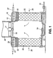
- a cooling tower 10 includes a casing 12 in which one or more contact bodies 22 constructed in accordance with the present invention are mounted.
- the base of casing 12 is formed into a sump 23 having a float 24 and drainage line 25.
- Gas, such as air enters the channels or ducts within the contact bodies at the air inlet edge portion 26 thereof and is drawn upwardly, within the apparatus, to an outlet 29 equipped with a fan 30 and motor 31.
- Liquid, such as water, is introduced into the evaporative cooling apparatus or cooling tower through a liquid supply line 27 and escapes from the line through perforations or nozzles 28 or the like in the well known manner.
- the liquid escaping from the supply line 28 passes through a distribution pad 32 of conventional construction into the top of the contact bodies 22.
- the body consists of a plurality of corrugated sheets 33, 34, 35, 36 with the corrugations in adjacent sheets, e.g. 33 and 34, being disposed at an angle to each other and the corrugations in alternate sheets, such as 33, 35, being disposed in parallel, whereby a plurality of criss-crossing passages are formed within the contact body.
- the sheets are positioned at unequal angles to each other as is known in the art.
- the corrugations are generally at an angle relative to the horizontal so as to permit the gravity flow of liquid therethrough.
- the particular angular relationship of the sheets to one another, and to the horizontal, may be varied from apparatus to apparatus depending upon the particular construction to be achieved or function to be performed thereby.
- the corrugations and the corrugated sheets have a height or amplitude up from 5 to 40 or 60 millimeters and a width of 10 to 30 millimeters.
- the corrugated sheets may be adhered to one another at points of contact within the contact body or may be held in a fixed position by suitable spacing and retaining means at their edges.
- Contact bodies having the general construction illustrated in Figs. 2, 3 and 4 have been formed from a variety of materials including corrugated plastic sheets or sheets of fibrous, woven or non-woven material, such as for example glass, Kraft paper, or cotton. Such fibrous materials are typically porous and may be impregnated with resins, as for example is discussed in U.S. Pat. No. 3,862,280 in order to provide a degree of rigidity and wet strength.
- the contact body tends to collect dirt and dust passing through it with the air.
- algae growth is encouraged by the exposure to sunlight, moisture and nutrients contained in the air and water passing over the contact body. This growth occurs principally on the surface portions of the corrugations that will be exposed to the sun on the inlet portions 26 of the contact bodies.
- this problem with previously proposed contact bodies is overcome by the provision of a protective layer on at least the air inlet edge of the evaporative cooling media which will prevent deposition and absorption of solids and nutrients onto the substrate.
- a protective surface which also dries out as soon as the water is turned off, algae growth is prevented.
- each of the sheets of corrugated material is coated with a water resistant, water impermeable material 40 which is hydrophilic.
- This feature of the material causes the water passing through the contact body to spread out on the surface of the coating into a thin film which continuously washes the edge of the contact body to remove dirt, spores, and other contamination therefrom.
- the edge dries immediately. Thus, it will not retain water which would otherwise sustain algae growth. Accordingly, the edge of the contact body is protected while the remainder of the contact body, which is not subject to the collection of dirt or the exposure of sunlight, functions in its usual way.
- a protective layer composed of a latex acrylic, rubber or plastic base material applied to the edge of the contact body adequately protects the contact body.
- the protective layer is applied to the air inlet edge of the contact body by the apparatus shown in Figure 5 . More specifically, contact bodies 26, only one of which is shown in Figure 5 , are carried on a conveyor beneath a spray stand 52 in a spray enclosure (not shown).
- the spray stand 52 includes a nozzle support bar 54 extending transversely across the path of conveyor 50.
- Bar 54 has a plurality of nozzle support arms 56 or the like mounted thereon.
- a spray nozzle is adjustably mounted on each of the arms and connected by hoses 60 to a supply of the protective coating.
- the spray nozzles are of conventional construction and produce a fan like spray which, as seen in Fig. 5 , is directed downwardly at an angle toward the upwardly facing inlet surface portion 26 of contact body 22.
- nozzle angles relative to the contact body moving beneath it can be adjusted in any known or convenient manner as would readily appear to those skilled in the liquid spraying arts.
- the coating material is liquid and ejected from the nozzles in a fan like pattern that forms droplets of coating as it moves away from the nozzles.
- the spray of coating droplets will be intersected by the surfaces of the corrugated sheets along inlet edge 26.
- the spray cannot penetrate deeply into the channels formed between the corrugations and becomes less dense the further in the droplets penetrate.
- Most droplets are captured by the surfaces of the corrugations that directly face the spray path and those surfaces block spray from hitting surfaces of adjacent corrugations immediately behind them.
- the coating is most dense at the edges of the sheets and decreases in density further away from that edge leaving increasing surface area of the porous sheets exposed.
- portions of the corrugations which are blocked from spray by adjacent sheets have few if any droplets applied so that the porous sheet is exposed in those areas essentially up to the edge.
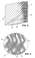
- the inclined surfaces of the corrugations are heavily coated at the edges of the sheets and the central valleys between them are essentially uncoated. It is only those inclined surfaces that will be exposed to the sun. Moreover, as best seen in Fig. 2 the density of the coating decreases at points away from edge thereby exposing more and more of the porous sheets.
- the coating used in accordance with the present invention does not retain water because it is water impermeable. Therefore, it dries out completely when water stops being distributed through the contact body. Moreover, algae spores will not adhere to the coating because it is smooth and will not allow the algae to embed itself in the fibers of the substrate. Furthermore, algae spores which fall onto the edge are washed away with the water or moved into the contact body where they cannot be exposed to the sunlight.
- the coating also provides ultra violet protection to the edge portions of the sheet.
Landscapes
- Engineering & Computer Science (AREA)
- Mechanical Engineering (AREA)
- General Engineering & Computer Science (AREA)
- Thermal Sciences (AREA)
- Physics & Mathematics (AREA)
- Chemical Kinetics & Catalysis (AREA)
- Chemical & Material Sciences (AREA)
- Separation Of Particles Using Liquids (AREA)
- Gas Separation By Absorption (AREA)
- Details Or Accessories Of Spraying Plant Or Apparatus (AREA)
- Physical Or Chemical Processes And Apparatus (AREA)
- Application Of Or Painting With Fluid Materials (AREA)
- Vaporization, Distillation, Condensation, Sublimation, And Cold Traps (AREA)
Abstract
Description
- The present invention relates to contact bodies for evaporative cooling apparatus and the like and a method of forming the coating.
- Cooling towers and evaporative coolers or the like remove heat from water by causing water to gravitate through a fill assembly in heat exchange relationship with currents of air. As a result the temperature of the water is lowered by the surface evaporation of the water before being returned to the equipment employing the water for various thermal interchange functions.
- It has been well known to form contact bodies for use in these apparatus from a plurality of sheets of corrugated materials defining a plurality of channels or ducts in the contact body through which gas and liquid are passed. One such well known contact body is disclosed for example in
U.S. Pat. No. 3,500,615 . Such contact bodies are formed from a range of materials including Kraft paper, fiberglass, plastic, and other materials often porous materials as well as impregnated materials as shown for example inU.S. Pat. No. 3,862,280 . - Gas contact bodies of this type have distinct advantages in cooling towers and evaporative cooling apparatus. Among the few disadvantages are that such contact bodies also serve as excellent air filters and breeding grounds for algae. This is particularly true along the air inlet side of the contact body which encounters the most dirt and atmospheric impurities, and is also exposed to sunlight. Accordingly, this portion of the contact body is subject to contamination and clogging as a result of dust and dirt entering the contact body.
- To combat this problem and to remove the dust and dirt filtered from the air, it has previously been proposed to flush the contact body with copious amounts of water. If this is not done and the debris is allowed to dry on the substrate of the contact body (particularly if it is a porous substrate such as Kraft paper, fiberglass or cotton) the dust, dirt, spores and minerals captured by the contact body will deposit and solidify throughout the fibers of the contact body sheets. These deposits then are difficult to remove without destroying the fiber substrate. If left unattended, the air entering face of the media eventually may be completely clogged.
- In addition to contamination from dirt and other airborne impurities, it has been found that algae will form at the interface between the wetted contact media and the sunlight, typically on the inlet side by also possibly on the outlet side of the contact body. Given the construction of the typical evaporative cooling apparatus, it is the first one-quarter to one inch of the channels of the media which will be exposed to sunlight and subject to the proliferation of algae in the presence of the light, nutrients and moisture.
- One attempt to overcome these problems is proposed in
U.S. Patent No. 5,248,454 which discloses a gas - liquid contact body formed of a plurality of facially opposed corrugated-sheets with the corrugation in alternate sheets being disposed in parallel to form a plurality of criss-crossing channels for gas and liquid. The air inlet side of the contact body has an air inlet portion coated with a water impermeable hydrophilic material containing an algaecide. That system does an excellent job of preventing algae growth and damage to the leading edge of the cooling media. However, the coating, which is usually formed of a water impervious material, creates an abrupt interface at the inner edge of the coating with the porous sheet. Because evaporative cooling pads are engineered with porous substrates that hold and transfer water the surface is 100% available for evaporation and the substrate evens out the distribution of water over the surface of the evaporative medium. The prior art solution of coating the edges of the substrate inhibits evaporation at the edge of the cooling pad in the area where the air entering is hottest and driest. - It is an object of the present invention to provide a contact body for cooling towers and evaporative coolers which has improved operating efficiencies.
- Another object of the present invention is to provide a contact body which has a self-cleaning air inlet and/or air outlet edge portion.
- Another object of the present invention is to provide a contact body which has an edge portion which will resist the deposition and proliferation of algae.
- In accordance with an aspect of the present invention, a gas-liquid contact body for use in a gas-liquid contact apparatus, said contact body comprising a plurality of facially opposed corrugated sheets with the corrugations in alternate sheets being disposed in parallel to form a plurality of criss-crossing channels for gas and liquid, said contact body having an air inlet side including an air inlet edge and an inlet edge portion downstream of said edge, said air inlet edge portion being coated with a water-impermeable hydrophilic material whose density of coverage decreases from a maximum of said air inlet edge downstream, within said air inlet portion to expose progressively increasing areas of said sheets to the air.
- The sheets of the contact body may define a plurality of intersecting and intercommunicating passages allowing the passage of gas and liquid therethrough. The corrugations in each of the sheets may extend at an angle to the main direction of flow of gas through the contact body, with the corrugations and alternate strips being disposed at an angle to the corrugations in the strips disposed between the alternate strips. The gas inlet edge of the contact body is coated with a water impermeable hydrophilic material containing an algicide of varying density from the edge of the sheets inwardly. The corrugations may be coated so that the surfaces of the corrugations facing the sun are more densely coated and those facing away from the sun when installed are more lightly coated. The coating's coverage of these surfaces decreases inwardly from the edge of the sheets. As a result water can travel through the porous substrate to be made available for evaporation at the leading edge while the surfaces most susceptible to algae growth are protected.
- The above, and other objects, features and advantages of this invention will be apparent in the following detailed description of an illustrative embodiment thereof, which is to be read in connection with the accompanying drawings, wherein:
-
Fig. 1 is a vertical longitudinal sectional view of one embodiment of a cooling tower adapted to contain contact bodies constructed in accordance with the present invention; -
Fig. 2 is a perspective view, partly in section, of a contact body constructed in accordance with the present invention and adapted to be used in the tower ofFig. 1 ; -
Fig. 3 is a fragmentary enlarged view of the air inlet edge portion of the contact body ofFig. 2 ; -
Fig. 4A is a further enlarged view of the edge of the air inlet portion of the single sheet of the contact body; -
Fig. 4B is a view similar toFigure 4A of the same sheet, inverted; andFig. 5 is a schematic illustration of a spray booth for coating the edge portions of the contact body. - Referring now to the drawings in detail, and initially to
Fig. 1 thereof, acooling tower 10 includes acasing 12 in which one ormore contact bodies 22 constructed in accordance with the present invention are mounted. The base ofcasing 12 is formed into asump 23 having afloat 24 anddrainage line 25. Gas, such as air, enters the channels or ducts within the contact bodies at the airinlet edge portion 26 thereof and is drawn upwardly, within the apparatus, to anoutlet 29 equipped with afan 30 andmotor 31. Liquid, such as water, is introduced into the evaporative cooling apparatus or cooling tower through aliquid supply line 27 and escapes from the line through perforations ornozzles 28 or the like in the well known manner. The liquid escaping from thesupply line 28 passes through adistribution pad 32 of conventional construction into the top of thecontact bodies 22. - Contact
body 22 in accordance with the present inventions is illustrated in greater detail inFigs. 2 through 4 . The body consists of a plurality ofcorrugated sheets - As seen in
Fig. 1 , when the contact bodies are mounted in the evaporative cooling apparatus, the corrugations are generally at an angle relative to the horizontal so as to permit the gravity flow of liquid therethrough. The particular angular relationship of the sheets to one another, and to the horizontal, may be varied from apparatus to apparatus depending upon the particular construction to be achieved or function to be performed thereby. - Typically, the corrugations and the corrugated sheets have a height or amplitude up from 5 to 40 or 60 millimeters and a width of 10 to 30 millimeters. The corrugated sheets may be adhered to one another at points of contact within the contact body or may be held in a fixed position by suitable spacing and retaining means at their edges.
- Contact bodies having the general construction illustrated in
Figs. 2, 3 and4 have been formed from a variety of materials including corrugated plastic sheets or sheets of fibrous, woven or non-woven material, such as for example glass, Kraft paper, or cotton. Such fibrous materials are typically porous and may be impregnated with resins, as for example is discussed inU.S. Pat. No. 3,862,280 in order to provide a degree of rigidity and wet strength. As noted above, the contact body tends to collect dirt and dust passing through it with the air. At the edge of the contact bodies algae growth is encouraged by the exposure to sunlight, moisture and nutrients contained in the air and water passing over the contact body. This growth occurs principally on the surface portions of the corrugations that will be exposed to the sun on theinlet portions 26 of the contact bodies. - In accordance with the present invention, this problem with previously proposed contact bodies is overcome by the provision of a protective layer on at least the air inlet edge of the evaporative cooling media which will prevent deposition and absorption of solids and nutrients onto the substrate. By providing a protective surface which also dries out as soon as the water is turned off, algae growth is prevented.
- More in particular, the air inlet edges of each of the sheets of corrugated material is coated with a water resistant, water
impermeable material 40 which is hydrophilic. This feature of the material causes the water passing through the contact body to spread out on the surface of the coating into a thin film which continuously washes the edge of the contact body to remove dirt, spores, and other contamination therefrom. When the water is turned off, the edge dries immediately. Thus, it will not retain water which would otherwise sustain algae growth. Accordingly, the edge of the contact body is protected while the remainder of the contact body, which is not subject to the collection of dirt or the exposure of sunlight, functions in its usual way. - It has been found that a protective layer composed of a latex acrylic, rubber or plastic base material applied to the edge of the contact body adequately protects the contact body.
- The protective layer is applied to the air inlet edge of the contact body by the apparatus shown in
Figure 5 . More specifically,contact bodies 26, only one of which is shown inFigure 5 , are carried on a conveyor beneath aspray stand 52 in a spray enclosure (not shown). - The spray stand 52 includes a
nozzle support bar 54 extending transversely across the path ofconveyor 50.Bar 54 has a plurality ofnozzle support arms 56 or the like mounted thereon. A spray nozzle is adjustably mounted on each of the arms and connected byhoses 60 to a supply of the protective coating. The spray nozzles are of conventional construction and produce a fan like spray which, as seen inFig. 5 , is directed downwardly at an angle toward the upwardly facinginlet surface portion 26 ofcontact body 22. In the illustrative embodiment there are fournozzles 60, two (60a, 60b) facing down and in the direction of travel of the conveyor and the other two (60c and 60d) facing down and opposite the direction of travel of the conveyor. - The nozzle angles relative to the contact body moving beneath it can be adjusted in any known or convenient manner as would readily appear to those skilled in the liquid spraying arts.
- The coating material is liquid and ejected from the nozzles in a fan like pattern that forms droplets of coating as it moves away from the nozzles. As will be apparent, the spray of coating droplets will be intersected by the surfaces of the corrugated sheets along
inlet edge 26. The spray cannot penetrate deeply into the channels formed between the corrugations and becomes less dense the further in the droplets penetrate. Most droplets are captured by the surfaces of the corrugations that directly face the spray path and those surfaces block spray from hitting surfaces of adjacent corrugations immediately behind them. As a result the coating is most dense at the edges of the sheets and decreases in density further away from that edge leaving increasing surface area of the porous sheets exposed. In addition, portions of the corrugations which are blocked from spray by adjacent sheets have few if any droplets applied so that the porous sheet is exposed in those areas essentially up to the edge. - Thus, as seen in
Figure 2-4 , the inclined surfaces of the corrugations are heavily coated at the edges of the sheets and the central valleys between them are essentially uncoated. It is only those inclined surfaces that will be exposed to the sun. Moreover, as best seen inFig. 2 the density of the coating decreases at points away from edge thereby exposing more and more of the porous sheets. - As a result of this arrangement, water can travel through the porous substrate up to the free edge thereof where it is available to the hottest and driest air for evaporation while still providing protection for the sheet edges and self cleaning anti-algae forming action. Thus, as compared to the prior art, far more surface area is available at
edge portion 26 for evaporative cooling of the hot dry air. - As noted, the coating used in accordance with the present invention does not retain water because it is water impermeable. Therefore, it dries out completely when water stops being distributed through the contact body. Moreover, algae spores will not adhere to the coating because it is smooth and will not allow the algae to embed itself in the fibers of the substrate. Furthermore, algae spores which fall onto the edge are washed away with the water or moved into the contact body where they cannot be exposed to the sunlight. The coating also provides ultra violet protection to the edge portions of the sheet.
- It has been found that a preferred coating for this purpose can be formulated as follows:
- Latex rubber acrylic or plastic (i.e. PVC) 65-70 parts;
- Kaolin or hydrated alumina 25-30 parts;
- Titanium dioxide or carbon black 1-5 parts;
- Silicone 0.001 to 1 part;
- Other composition may also be used.
- Although an illustrative embodiment of the present invention described herein with reference to the accompanying drawings, it is to be understood that the invention is not limited to that precise embodiment and that various changes and modifications may be affected therein by one skilled in the art without departing from the scope of this invention as defined by the claims.
Claims (6)
- A gas-liquid contact body (22) for use in a gas-liquid contact apparatus, said contact body (22) comprising a plurality of facially opposed corrugated sheets (33, 34, 35, 36) with the corrugations in alternate sheets being disposed in parallel to form a plurality of criss-crossing channels for gas and liquid, said contact body (22) having an air inlet side including an air inlet edge (26) and an inlet edge portion downstream of said edge(26), said air inlet edge portion being coated with a water-impermeable hydrophilic material, characterized in that its density of coverage decreases from a maximum of said air inlet edge (26) downstream, within said air inlet portion to expose progressively increasing areas of said sheets (33, 34, 35, 36) to the air.
- A gas-liquid contact body (22) as defined in claim 1, wherein portions of said corrugated sheets (33, 34, 35, 36) in said inlet edge portion are essentially uncoated.
- A gas-liquid contact body (22) as defined in claim 1, for use in a gas and liquid contact apparatus having a casing (12), a gas inlet side and a gas outlet side, wherein the plurality of corrugated sheets (33, 34, 35, 36) define the gas inlet edge (26) which is adapted to be positioned adjacent said gas inlet side of a casing (12), and the plurality of criss-crossing channels are intersecting and intercommunicating passages that allow the passage of gas and liquid therethrough, the corrugations in each of said sheets (33, 34, 35, 36) extending at an angle to the main section of flow of the gas through the body (22) with the corrugations in alternate strips being disposed at an angle to the corrugations in the adjacent strips, an inlet edge portion downstream of said gas inlet edge (26) being coated with a water-impermeable hydrophilic material whose density of coverage decreases from a maximum of said air inlet edge downstream, within said air inlet portion to expose progressively increasing areas of said sheets (33,34, 35, 36) to the air.
- A gas liquid contact body (22) as defined in claim 1 wherein said coating includes a material selected from the group consisting of latex rubber, acrylic or plastic.
- The method of coating an air inlet edge portion of a contact body (22) comprising a plurality of facially opposed corrugated sheets (33, 34, 35, 36), characterized in that it comprises the steps of:moving said contact body (22) relative to a plurality of coating spray nozzles (28) with said air inlet edge portion facing the nozzles(28),positioning the nozzles (28) at angles to the surface of the contact body(22); andspraying coating material in droplet form towards said contact body (22) and its air inlet portion,whereby the density of the coating on the surfaces of the air inlet portion decreases from a maximum at the surface of the body (22) facing the nozzles downstream within the air inlet portion to leave progressively increasing areas of said sheets (33, 34, 35, 36) exposed to air.
- The method as defined in claim 5, including the step of directing the nozzles (28) at an angle to the surface of the contact body (22) whereby predetermined portions of the surface of the corrugations are sprayed with coating and other portions are blocked from spray by adjacent courugations.
Applications Claiming Priority (2)
| Application Number | Priority Date | Filing Date | Title |
|---|---|---|---|
| US11/518,959 US7717406B2 (en) | 2006-09-12 | 2006-09-12 | Algae resistant edge coating and method of forming same |
| PCT/US2007/019750 WO2008033354A2 (en) | 2006-09-12 | 2007-09-12 | Algae resistant edge coating and method of forming same |
Publications (3)
| Publication Number | Publication Date |
|---|---|
| EP2061581A2 EP2061581A2 (en) | 2009-05-27 |
| EP2061581A4 EP2061581A4 (en) | 2013-01-02 |
| EP2061581B1 true EP2061581B1 (en) | 2013-12-18 |
Family
ID=39184301
Family Applications (1)
| Application Number | Title | Priority Date | Filing Date |
|---|---|---|---|
| EP07811745.4A Active EP2061581B1 (en) | 2006-09-12 | 2007-09-12 | Gas-liquid contact body and method of coating |
Country Status (16)
| Country | Link |
|---|---|
| US (1) | US7717406B2 (en) |
| EP (1) | EP2061581B1 (en) |
| JP (1) | JP4965658B2 (en) |
| KR (1) | KR101313564B1 (en) |
| CN (1) | CN101516485B (en) |
| AU (1) | AU2007294930B2 (en) |
| BR (1) | BRPI0715003B1 (en) |
| CA (1) | CA2662475C (en) |
| EG (1) | EG25232A (en) |
| ES (1) | ES2449101T3 (en) |
| IL (1) | IL197521A (en) |
| MX (1) | MX2009002605A (en) |
| NZ (1) | NZ575112A (en) |
| RU (1) | RU2417827C2 (en) |
| WO (1) | WO2008033354A2 (en) |
| ZA (1) | ZA200901209B (en) |
Families Citing this family (10)
| Publication number | Priority date | Publication date | Assignee | Title |
|---|---|---|---|---|
| CA2952522A1 (en) | 2014-06-20 | 2015-12-23 | Nortek Air Solutions Canada, Inc. | Systems and methods for managing conditions in enclosed space |
| DE202014102836U1 (en) * | 2014-06-23 | 2015-09-24 | B+M Textil Gmbh & Co. Kg | cooling unit |
| US11092349B2 (en) | 2015-05-15 | 2021-08-17 | Nortek Air Solutions Canada, Inc. | Systems and methods for providing cooling to a heat load |
| CN107850335B (en) | 2015-05-15 | 2021-02-19 | 北狄空气应对加拿大公司 | Liquid cooling using liquid-gas membrane energy exchangers |
| US10299408B1 (en) * | 2015-08-06 | 2019-05-21 | Amazon Technologies, Inc. | Cooling system for a building |
| RU2610369C1 (en) * | 2015-10-28 | 2017-02-09 | Федеральное государственное бюджетное образовательное учреждение высшего образования "Юго-Западный государственный университет" (ЮЗГУ) | Cooling tower using surface cooling |
| US10834855B2 (en) | 2016-01-08 | 2020-11-10 | Nortek Air Solutions Canada, Inc. | Integrated make-up air system in 100% air recirculation system |
| EP3306246B1 (en) * | 2016-10-06 | 2020-09-30 | Jaeggi HybridTechnologie AG | Heat exchange device |
| US12480669B2 (en) * | 2020-03-19 | 2025-11-25 | Resideo Llc | Wall mounted bypass humidifier |
| CN112665409B (en) * | 2020-12-22 | 2022-07-26 | 厦门烟草工业有限责任公司 | Cooling tower and refrigeration system |
Family Cites Families (13)
| Publication number | Priority date | Publication date | Assignee | Title |
|---|---|---|---|---|
| US3286999A (en) * | 1964-07-02 | 1966-11-22 | Mitsubishi Plastics Ind | Cooling tower |
| SE311371B (en) * | 1966-01-26 | 1969-06-09 | Munters C | |
| SE325589B (en) * | 1967-02-21 | 1970-07-06 | C G Munters | |
| US3798057A (en) * | 1971-10-05 | 1974-03-19 | Munters Ab Carl | Impregnated fibrous web structures |
| US3862280A (en) * | 1971-10-05 | 1975-01-21 | Munters Ab Carl | Apparatus for gas-liquid contact |
| JPS53148149A (en) * | 1977-05-30 | 1978-12-23 | Nippon Steel Corp | Method of treating water |
| JPH02110298A (en) * | 1988-10-18 | 1990-04-23 | Takuma Co Ltd | cooling tower |
| JP3080679B2 (en) * | 1991-04-18 | 2000-08-28 | 株式会社テクノ菱和 | cooling tower |
| JPH0545090A (en) * | 1991-08-09 | 1993-02-23 | Matsushita Electric Ind Co Ltd | cooling tower |
| US5248454A (en) * | 1992-04-10 | 1993-09-28 | Munters Corporation | Algae resistant edge coating |
| JP2001316631A (en) * | 2000-05-11 | 2001-11-16 | Fukuda Metal Foil & Powder Co Ltd | Copper paint for algae prevention and algae prevention method using the copper paint |
| US7114621B2 (en) * | 2001-12-14 | 2006-10-03 | 3M Innovative Properties Company | Membrane module elements |
| CN1829845A (en) * | 2003-05-26 | 2006-09-06 | 洛格斯革新有限公司 | device for capturing moisture in the air |
-
2006
- 2006-09-12 US US11/518,959 patent/US7717406B2/en active Active
-
2007
- 2007-09-12 WO PCT/US2007/019750 patent/WO2008033354A2/en not_active Ceased
- 2007-09-12 CN CN2007800337615A patent/CN101516485B/en not_active Expired - Fee Related
- 2007-09-12 JP JP2009528258A patent/JP4965658B2/en not_active Expired - Fee Related
- 2007-09-12 CA CA2662475A patent/CA2662475C/en not_active Expired - Fee Related
- 2007-09-12 RU RU2009113561/05A patent/RU2417827C2/en not_active IP Right Cessation
- 2007-09-12 NZ NZ575112A patent/NZ575112A/en not_active IP Right Cessation
- 2007-09-12 MX MX2009002605A patent/MX2009002605A/en active IP Right Grant
- 2007-09-12 ES ES07811745.4T patent/ES2449101T3/en active Active
- 2007-09-12 AU AU2007294930A patent/AU2007294930B2/en not_active Ceased
- 2007-09-12 BR BRPI0715003-2A patent/BRPI0715003B1/en not_active IP Right Cessation
- 2007-09-12 KR KR1020097004792A patent/KR101313564B1/en not_active Expired - Fee Related
- 2007-09-12 EP EP07811745.4A patent/EP2061581B1/en active Active
-
2008
- 2008-05-07 ZA ZA200901209A patent/ZA200901209B/en unknown
-
2009
- 2009-03-10 IL IL197521A patent/IL197521A/en not_active IP Right Cessation
- 2009-03-12 EG EG2009030329A patent/EG25232A/en active
Also Published As
| Publication number | Publication date |
|---|---|
| JP4965658B2 (en) | 2012-07-04 |
| BRPI0715003A2 (en) | 2013-05-28 |
| ES2449101T3 (en) | 2014-03-18 |
| IL197521A0 (en) | 2009-12-24 |
| EP2061581A4 (en) | 2013-01-02 |
| WO2008033354A2 (en) | 2008-03-20 |
| US20090032981A1 (en) | 2009-02-05 |
| WO2008033354A3 (en) | 2008-11-13 |
| MX2009002605A (en) | 2009-03-20 |
| CN101516485A (en) | 2009-08-26 |
| US7717406B2 (en) | 2010-05-18 |
| CA2662475C (en) | 2014-08-05 |
| AU2007294930A1 (en) | 2008-03-20 |
| JP2010503821A (en) | 2010-02-04 |
| NZ575112A (en) | 2011-12-22 |
| KR101313564B1 (en) | 2013-10-01 |
| AU2007294930B2 (en) | 2010-12-09 |
| BRPI0715003B1 (en) | 2020-08-25 |
| ZA200901209B (en) | 2010-03-31 |
| RU2009113561A (en) | 2010-10-20 |
| RU2417827C2 (en) | 2011-05-10 |
| IL197521A (en) | 2013-03-24 |
| KR20090060414A (en) | 2009-06-12 |
| EP2061581A2 (en) | 2009-05-27 |
| EG25232A (en) | 2011-11-17 |
| CA2662475A1 (en) | 2008-03-20 |
| CN101516485B (en) | 2011-11-16 |
Similar Documents
| Publication | Publication Date | Title |
|---|---|---|
| AU2007294930B2 (en) | Algae resistant edge coating and method of forming same | |
| US5248454A (en) | Algae resistant edge coating | |
| EP0580792B1 (en) | Alternating sheet evaporative cooling pad | |
| EP1042642B1 (en) | Air treatment unit | |
| US20090166902A1 (en) | Counter flow type of cooling tower generating low grade of noise | |
| US4328176A (en) | Apparatus for damping the noise in cooling towers | |
| US6435963B1 (en) | Barrier device to surround air delivery structures | |
| CN100535567C (en) | Internal inserts in cooling towers | |
| EP0087229B1 (en) | Separating devices and methods | |
| JP2816364B2 (en) | Filling plate for gas-liquid contact | |
| JP3371043B2 (en) | Eliminator for spray humidifier | |
| JPH08626Y2 (en) | Cross flow type cooling tower | |
| JPH0664068U (en) | Fluid transfer sheet | |
| JP2690858B2 (en) | cooling tower | |
| RU2232367C1 (en) | Water cooling tower | |
| JPH11287568A (en) | Water splash prevention structure of crossflow cooling tower | |
| JPH09243181A (en) | Fluid transferring sheet | |
| JP2010031636A (en) | Ceiling base material and structure using the same | |
| JPH0664066U (en) | Regular line sheet | |
| HK1071191B (en) | Internal inserts in cooling towers | |
| JP2005291658A (en) | Droplet scattering prevention method, forced draft cooling tower, droplet scattering amount measuring method and droplet scattering amount measuring apparatus | |
| JPH11132691A (en) | Water splash prevention device for crossflow cooling tower | |
| JP2007107363A (en) | Sprinkling heat-exchange method for gradual corrugated roof | |
| JPH0741261U (en) | Heat exchange device by double-sided normal flow |
Legal Events
| Date | Code | Title | Description |
|---|---|---|---|
| PUAI | Public reference made under article 153(3) epc to a published international application that has entered the european phase |
Free format text: ORIGINAL CODE: 0009012 |
|
| 17P | Request for examination filed |
Effective date: 20090304 |
|
| AK | Designated contracting states |
Kind code of ref document: A2 Designated state(s): AT BE BG CH CY CZ DE DK EE ES FI FR GB GR HU IE IS IT LI LT LU LV MC MT NL PL PT RO SE SI SK TR |
|
| AX | Request for extension of the european patent |
Extension state: AL BA HR MK RS |
|
| DAX | Request for extension of the european patent (deleted) | ||
| REG | Reference to a national code |
Ref country code: DE Ref legal event code: R079 Ref document number: 602007034352 Country of ref document: DE Free format text: PREVIOUS MAIN CLASS: B01F0003040000 Ipc: F28C0001040000 |
|
| A4 | Supplementary search report drawn up and despatched |
Effective date: 20121130 |
|
| RIC1 | Information provided on ipc code assigned before grant |
Ipc: F28C 1/04 20060101AFI20121126BHEP Ipc: F28F 25/08 20060101ALI20121126BHEP |
|
| GRAP | Despatch of communication of intention to grant a patent |
Free format text: ORIGINAL CODE: EPIDOSNIGR1 |
|
| INTG | Intention to grant announced |
Effective date: 20130710 |
|
| GRAS | Grant fee paid |
Free format text: ORIGINAL CODE: EPIDOSNIGR3 |
|
| GRAA | (expected) grant |
Free format text: ORIGINAL CODE: 0009210 |
|
| AK | Designated contracting states |
Kind code of ref document: B1 Designated state(s): AT BE BG CH CY CZ DE DK EE ES FI FR GB GR HU IE IS IT LI LT LU LV MC MT NL PL PT RO SE SI SK TR |
|
| REG | Reference to a national code |
Ref country code: GB Ref legal event code: FG4D |
|
| REG | Reference to a national code |
Ref country code: CH Ref legal event code: EP |
|
| REG | Reference to a national code |
Ref country code: AT Ref legal event code: REF Ref document number: 645809 Country of ref document: AT Kind code of ref document: T Effective date: 20140115 |
|
| REG | Reference to a national code |
Ref country code: IE Ref legal event code: FG4D |
|
| REG | Reference to a national code |
Ref country code: DE Ref legal event code: R096 Ref document number: 602007034352 Country of ref document: DE Effective date: 20140213 |
|
| REG | Reference to a national code |
Ref country code: ES Ref legal event code: FG2A Ref document number: 2449101 Country of ref document: ES Kind code of ref document: T3 Effective date: 20140318 |
|
| REG | Reference to a national code |
Ref country code: NL Ref legal event code: VDEP Effective date: 20131218 |
|
| PG25 | Lapsed in a contracting state [announced via postgrant information from national office to epo] |
Ref country code: SE Free format text: LAPSE BECAUSE OF FAILURE TO SUBMIT A TRANSLATION OF THE DESCRIPTION OR TO PAY THE FEE WITHIN THE PRESCRIBED TIME-LIMIT Effective date: 20131218 Ref country code: LT Free format text: LAPSE BECAUSE OF FAILURE TO SUBMIT A TRANSLATION OF THE DESCRIPTION OR TO PAY THE FEE WITHIN THE PRESCRIBED TIME-LIMIT Effective date: 20131218 Ref country code: FI Free format text: LAPSE BECAUSE OF FAILURE TO SUBMIT A TRANSLATION OF THE DESCRIPTION OR TO PAY THE FEE WITHIN THE PRESCRIBED TIME-LIMIT Effective date: 20131218 |
|
| REG | Reference to a national code |
Ref country code: AT Ref legal event code: MK05 Ref document number: 645809 Country of ref document: AT Kind code of ref document: T Effective date: 20131218 |
|
| REG | Reference to a national code |
Ref country code: LT Ref legal event code: MG4D |
|
| PG25 | Lapsed in a contracting state [announced via postgrant information from national office to epo] |
Ref country code: LV Free format text: LAPSE BECAUSE OF FAILURE TO SUBMIT A TRANSLATION OF THE DESCRIPTION OR TO PAY THE FEE WITHIN THE PRESCRIBED TIME-LIMIT Effective date: 20131218 |
|
| PG25 | Lapsed in a contracting state [announced via postgrant information from national office to epo] |
Ref country code: BE Free format text: LAPSE BECAUSE OF FAILURE TO SUBMIT A TRANSLATION OF THE DESCRIPTION OR TO PAY THE FEE WITHIN THE PRESCRIBED TIME-LIMIT Effective date: 20131218 Ref country code: IS Free format text: LAPSE BECAUSE OF FAILURE TO SUBMIT A TRANSLATION OF THE DESCRIPTION OR TO PAY THE FEE WITHIN THE PRESCRIBED TIME-LIMIT Effective date: 20140418 Ref country code: EE Free format text: LAPSE BECAUSE OF FAILURE TO SUBMIT A TRANSLATION OF THE DESCRIPTION OR TO PAY THE FEE WITHIN THE PRESCRIBED TIME-LIMIT Effective date: 20131218 |
|
| PG25 | Lapsed in a contracting state [announced via postgrant information from national office to epo] |
Ref country code: NL Free format text: LAPSE BECAUSE OF FAILURE TO SUBMIT A TRANSLATION OF THE DESCRIPTION OR TO PAY THE FEE WITHIN THE PRESCRIBED TIME-LIMIT Effective date: 20131218 Ref country code: CY Free format text: LAPSE BECAUSE OF FAILURE TO SUBMIT A TRANSLATION OF THE DESCRIPTION OR TO PAY THE FEE WITHIN THE PRESCRIBED TIME-LIMIT Effective date: 20131218 Ref country code: PT Free format text: LAPSE BECAUSE OF FAILURE TO SUBMIT A TRANSLATION OF THE DESCRIPTION OR TO PAY THE FEE WITHIN THE PRESCRIBED TIME-LIMIT Effective date: 20140418 Ref country code: PL Free format text: LAPSE BECAUSE OF FAILURE TO SUBMIT A TRANSLATION OF THE DESCRIPTION OR TO PAY THE FEE WITHIN THE PRESCRIBED TIME-LIMIT Effective date: 20131218 Ref country code: RO Free format text: LAPSE BECAUSE OF FAILURE TO SUBMIT A TRANSLATION OF THE DESCRIPTION OR TO PAY THE FEE WITHIN THE PRESCRIBED TIME-LIMIT Effective date: 20131218 Ref country code: CZ Free format text: LAPSE BECAUSE OF FAILURE TO SUBMIT A TRANSLATION OF THE DESCRIPTION OR TO PAY THE FEE WITHIN THE PRESCRIBED TIME-LIMIT Effective date: 20131218 Ref country code: SK Free format text: LAPSE BECAUSE OF FAILURE TO SUBMIT A TRANSLATION OF THE DESCRIPTION OR TO PAY THE FEE WITHIN THE PRESCRIBED TIME-LIMIT Effective date: 20131218 Ref country code: AT Free format text: LAPSE BECAUSE OF FAILURE TO SUBMIT A TRANSLATION OF THE DESCRIPTION OR TO PAY THE FEE WITHIN THE PRESCRIBED TIME-LIMIT Effective date: 20131218 |
|
| REG | Reference to a national code |
Ref country code: DE Ref legal event code: R097 Ref document number: 602007034352 Country of ref document: DE |
|
| PLBE | No opposition filed within time limit |
Free format text: ORIGINAL CODE: 0009261 |
|
| STAA | Information on the status of an ep patent application or granted ep patent |
Free format text: STATUS: NO OPPOSITION FILED WITHIN TIME LIMIT |
|
| PG25 | Lapsed in a contracting state [announced via postgrant information from national office to epo] |
Ref country code: DK Free format text: LAPSE BECAUSE OF FAILURE TO SUBMIT A TRANSLATION OF THE DESCRIPTION OR TO PAY THE FEE WITHIN THE PRESCRIBED TIME-LIMIT Effective date: 20131218 |
|
| 26N | No opposition filed |
Effective date: 20140919 |
|
| REG | Reference to a national code |
Ref country code: DE Ref legal event code: R097 Ref document number: 602007034352 Country of ref document: DE Effective date: 20140919 |
|
| PG25 | Lapsed in a contracting state [announced via postgrant information from national office to epo] |
Ref country code: MC Free format text: LAPSE BECAUSE OF FAILURE TO SUBMIT A TRANSLATION OF THE DESCRIPTION OR TO PAY THE FEE WITHIN THE PRESCRIBED TIME-LIMIT Effective date: 20131218 Ref country code: LU Free format text: LAPSE BECAUSE OF FAILURE TO SUBMIT A TRANSLATION OF THE DESCRIPTION OR TO PAY THE FEE WITHIN THE PRESCRIBED TIME-LIMIT Effective date: 20140912 |
|
| REG | Reference to a national code |
Ref country code: CH Ref legal event code: PL |
|
| GBPC | Gb: european patent ceased through non-payment of renewal fee |
Effective date: 20140912 |
|
| PG25 | Lapsed in a contracting state [announced via postgrant information from national office to epo] |
Ref country code: SI Free format text: LAPSE BECAUSE OF FAILURE TO SUBMIT A TRANSLATION OF THE DESCRIPTION OR TO PAY THE FEE WITHIN THE PRESCRIBED TIME-LIMIT Effective date: 20131218 |
|
| REG | Reference to a national code |
Ref country code: IE Ref legal event code: MM4A |
|
| PG25 | Lapsed in a contracting state [announced via postgrant information from national office to epo] |
Ref country code: CH Free format text: LAPSE BECAUSE OF NON-PAYMENT OF DUE FEES Effective date: 20140930 Ref country code: GB Free format text: LAPSE BECAUSE OF NON-PAYMENT OF DUE FEES Effective date: 20140912 Ref country code: LI Free format text: LAPSE BECAUSE OF NON-PAYMENT OF DUE FEES Effective date: 20140930 |
|
| PG25 | Lapsed in a contracting state [announced via postgrant information from national office to epo] |
Ref country code: IE Free format text: LAPSE BECAUSE OF NON-PAYMENT OF DUE FEES Effective date: 20140912 |
|
| PG25 | Lapsed in a contracting state [announced via postgrant information from national office to epo] |
Ref country code: BG Free format text: LAPSE BECAUSE OF FAILURE TO SUBMIT A TRANSLATION OF THE DESCRIPTION OR TO PAY THE FEE WITHIN THE PRESCRIBED TIME-LIMIT Effective date: 20131218 |
|
| PG25 | Lapsed in a contracting state [announced via postgrant information from national office to epo] |
Ref country code: GR Free format text: LAPSE BECAUSE OF FAILURE TO SUBMIT A TRANSLATION OF THE DESCRIPTION OR TO PAY THE FEE WITHIN THE PRESCRIBED TIME-LIMIT Effective date: 20140319 Ref country code: MT Free format text: LAPSE BECAUSE OF FAILURE TO SUBMIT A TRANSLATION OF THE DESCRIPTION OR TO PAY THE FEE WITHIN THE PRESCRIBED TIME-LIMIT Effective date: 20131218 |
|
| PG25 | Lapsed in a contracting state [announced via postgrant information from national office to epo] |
Ref country code: HU Free format text: LAPSE BECAUSE OF FAILURE TO SUBMIT A TRANSLATION OF THE DESCRIPTION OR TO PAY THE FEE WITHIN THE PRESCRIBED TIME-LIMIT; INVALID AB INITIO Effective date: 20070912 |
|
| REG | Reference to a national code |
Ref country code: FR Ref legal event code: PLFP Year of fee payment: 10 |
|
| REG | Reference to a national code |
Ref country code: FR Ref legal event code: PLFP Year of fee payment: 11 |
|
| REG | Reference to a national code |
Ref country code: FR Ref legal event code: PLFP Year of fee payment: 12 |
|
| PGFP | Annual fee paid to national office [announced via postgrant information from national office to epo] |
Ref country code: IT Payment date: 20210924 Year of fee payment: 15 Ref country code: FR Payment date: 20210914 Year of fee payment: 15 |
|
| PGFP | Annual fee paid to national office [announced via postgrant information from national office to epo] |
Ref country code: TR Payment date: 20210813 Year of fee payment: 15 Ref country code: DE Payment date: 20210921 Year of fee payment: 15 |
|
| PGFP | Annual fee paid to national office [announced via postgrant information from national office to epo] |
Ref country code: ES Payment date: 20211008 Year of fee payment: 15 |
|
| REG | Reference to a national code |
Ref country code: DE Ref legal event code: R119 Ref document number: 602007034352 Country of ref document: DE |
|
| PG25 | Lapsed in a contracting state [announced via postgrant information from national office to epo] |
Ref country code: FR Free format text: LAPSE BECAUSE OF NON-PAYMENT OF DUE FEES Effective date: 20220930 Ref country code: DE Free format text: LAPSE BECAUSE OF NON-PAYMENT OF DUE FEES Effective date: 20230401 |
|
| REG | Reference to a national code |
Ref country code: ES Ref legal event code: FD2A Effective date: 20231027 |
|
| PG25 | Lapsed in a contracting state [announced via postgrant information from national office to epo] |
Ref country code: IT Free format text: LAPSE BECAUSE OF NON-PAYMENT OF DUE FEES Effective date: 20220912 |
|
| PG25 | Lapsed in a contracting state [announced via postgrant information from national office to epo] |
Ref country code: ES Free format text: LAPSE BECAUSE OF NON-PAYMENT OF DUE FEES Effective date: 20220913 |
|
| PG25 | Lapsed in a contracting state [announced via postgrant information from national office to epo] |
Ref country code: ES Free format text: LAPSE BECAUSE OF NON-PAYMENT OF DUE FEES Effective date: 20220913 |