EP2060789A1 - Screw pump and screw rotor - Google Patents
Screw pump and screw rotor Download PDFInfo
- Publication number
- EP2060789A1 EP2060789A1 EP07806598A EP07806598A EP2060789A1 EP 2060789 A1 EP2060789 A1 EP 2060789A1 EP 07806598 A EP07806598 A EP 07806598A EP 07806598 A EP07806598 A EP 07806598A EP 2060789 A1 EP2060789 A1 EP 2060789A1
- Authority
- EP
- European Patent Office
- Prior art keywords
- screw rotor
- circular arc
- curve
- screw
- arc portion
- Prior art date
- Legal status (The legal status is an assumption and is not a legal conclusion. Google has not performed a legal analysis and makes no representation as to the accuracy of the status listed.)
- Withdrawn
Links
Images




Classifications
-
- F—MECHANICAL ENGINEERING; LIGHTING; HEATING; WEAPONS; BLASTING
- F04—POSITIVE - DISPLACEMENT MACHINES FOR LIQUIDS; PUMPS FOR LIQUIDS OR ELASTIC FLUIDS
- F04C—ROTARY-PISTON, OR OSCILLATING-PISTON, POSITIVE-DISPLACEMENT MACHINES FOR LIQUIDS; ROTARY-PISTON, OR OSCILLATING-PISTON, POSITIVE-DISPLACEMENT PUMPS
- F04C2/00—Rotary-piston machines or pumps
- F04C2/08—Rotary-piston machines or pumps of intermeshing-engagement type, i.e. with engagement of co-operating members similar to that of toothed gearing
- F04C2/10—Rotary-piston machines or pumps of intermeshing-engagement type, i.e. with engagement of co-operating members similar to that of toothed gearing of internal-axis type with the outer member having more teeth or tooth-equivalents, e.g. rollers, than the inner member
- F04C2/107—Rotary-piston machines or pumps of intermeshing-engagement type, i.e. with engagement of co-operating members similar to that of toothed gearing of internal-axis type with the outer member having more teeth or tooth-equivalents, e.g. rollers, than the inner member with helical teeth
-
- F—MECHANICAL ENGINEERING; LIGHTING; HEATING; WEAPONS; BLASTING
- F04—POSITIVE - DISPLACEMENT MACHINES FOR LIQUIDS; PUMPS FOR LIQUIDS OR ELASTIC FLUIDS
- F04C—ROTARY-PISTON, OR OSCILLATING-PISTON, POSITIVE-DISPLACEMENT MACHINES FOR LIQUIDS; ROTARY-PISTON, OR OSCILLATING-PISTON, POSITIVE-DISPLACEMENT PUMPS
- F04C2/00—Rotary-piston machines or pumps
- F04C2/08—Rotary-piston machines or pumps of intermeshing-engagement type, i.e. with engagement of co-operating members similar to that of toothed gearing
- F04C2/12—Rotary-piston machines or pumps of intermeshing-engagement type, i.e. with engagement of co-operating members similar to that of toothed gearing of other than internal-axis type
- F04C2/14—Rotary-piston machines or pumps of intermeshing-engagement type, i.e. with engagement of co-operating members similar to that of toothed gearing of other than internal-axis type with toothed rotary pistons
- F04C2/16—Rotary-piston machines or pumps of intermeshing-engagement type, i.e. with engagement of co-operating members similar to that of toothed gearing of other than internal-axis type with toothed rotary pistons with helical teeth, e.g. chevron-shaped, screw type
-
- F—MECHANICAL ENGINEERING; LIGHTING; HEATING; WEAPONS; BLASTING
- F04—POSITIVE - DISPLACEMENT MACHINES FOR LIQUIDS; PUMPS FOR LIQUIDS OR ELASTIC FLUIDS
- F04C—ROTARY-PISTON, OR OSCILLATING-PISTON, POSITIVE-DISPLACEMENT MACHINES FOR LIQUIDS; ROTARY-PISTON, OR OSCILLATING-PISTON, POSITIVE-DISPLACEMENT PUMPS
- F04C18/00—Rotary-piston pumps specially adapted for elastic fluids
- F04C18/08—Rotary-piston pumps specially adapted for elastic fluids of intermeshing-engagement type, i.e. with engagement of co-operating members similar to that of toothed gearing
- F04C18/12—Rotary-piston pumps specially adapted for elastic fluids of intermeshing-engagement type, i.e. with engagement of co-operating members similar to that of toothed gearing of other than internal-axis type
- F04C18/14—Rotary-piston pumps specially adapted for elastic fluids of intermeshing-engagement type, i.e. with engagement of co-operating members similar to that of toothed gearing of other than internal-axis type with toothed rotary pistons
- F04C18/16—Rotary-piston pumps specially adapted for elastic fluids of intermeshing-engagement type, i.e. with engagement of co-operating members similar to that of toothed gearing of other than internal-axis type with toothed rotary pistons with helical teeth, e.g. chevron-shaped, screw type
Definitions
- the present invention relates to a screw pump that draws fluid into a housing and discharges the fluid to the exterior of the housing by rotating a pair of screw rotors.
- the present invention further relates to screw rotors in a screw pump.
- Patent Document 1 discloses a screw pump that has a pair of screw rotors engaged with each other. As the screw rotors rotate, the screw pump operates to transport fluid.
- a cross section of the tooth profile of a first conventional screw rotor 90A perpendicular to the rotor axis is shaped and sized equally with that of a second conventional screw rotor 90B.
- the cross section of the tooth profile of the first conventional screw rotor 90A perpendicular to the rotor axis is to the shape of the tooth profile of the first conventional screw rotor 90A on an imaginary plane extending perpendicular to the rotary axis of the first conventional screw rotor 90A.
- the cross section of the tooth profile of the first conventional screw rotor 90A perpendicular to the rotor axis includes a tooth top arc Q1R1, a tooth bottom arc S1T1, a first curve S1Q1, and a second curve T1R1.
- the first curve S1Q1 connects a first end S1 of the tooth bottom arc S1T1 to a first end Q1 of the tooth top arc Q1R1.
- the second curve T1R1 connects a second end T1 of the tooth bottom arc S1T1 to a second end R1 of the tooth top arc Q1R1.
- the cross section of the tooth profile of the second conventional screw rotor 90B perpendicular to the rotor axis includes a tooth top arc Q2R2, a tooth bottom arc S2T2, a first curve S2Q2, and a second curve T2R2.
- the first curve S2Q2 connects a first end S2 of the tooth bottom arc S2T2 to a first end Q2 of the tooth top arc Q2R2.
- the second curve T2R2 connects a second end T2 of the tooth bottom arc S2T2 to a second end R2 of the tooth top arc Q2R2.
- the first curve S1Q1 of the first conventional screw rotor 90A includes a trochoidal curve U1S1 and a connecting portion Q1U1.
- the trochoidal curve U1S1 is created by the path of the first end Q2 of the tooth top arc Q2R2 when the second conventional screw rotor 90B revolves about the first conventional screw rotor 90A.
- the connecting portion Q1U1 is a straight line that connects an end U1 of the trochoidal curve U1S1 to the first end Q1 of the tooth top arc Q1R1.
- the second curve T1R1 includes an outer circular arc R1W1, an involute curve W1Y1, and an inner circular arc Y1T1.
- the involute curve W1Y1 is located between the outer circular arc R1W1 and the inner circular arc Y1T1.
- the outer circular arc R1W1 is connected to the tooth top arc Q1R1 and the inner circular arc Y1T1 is connected to the tooth bottom arc S1T1.
- the first curve S2Q2 of the second conventional screw rotor 90B includes a trochoidal curve U2S2 and a connecting portion Q2U2, which is a straight line.
- the second curve T2R2 includes an outer circular arc R2W2, an involute curve W2Y2, and an inner circular arc Y2T2.
- first conventional screw rotor 90A nor the second conventional screw rotor 90B contacts the housing of the screw pump. Further, the first conventional screw rotor 90A and the second conventional screw rotor 90B do not contact each other. Such arrangement thus may potentially cause leakage of the fluid (leakage of gas). Although the tooth profiles of the first and second conventional screw rotors 90A, 90B are shaped in such a manner as to suppress the fluid leakage, the fluid leakage is desired to be suppressed further effectively.
- a screw pump including a housing, and a first screw rotor and a second screw rotor received in the housing is provided.
- the first screw rotor and the second screw rotor rotate in a direction in which the first and second screw rotors become engaged with each other.
- a fluid is drawn into the housing and then discharged to the exterior through rotation of the first screw rotor and the second screw rotor.
- a cross section of a tooth profile of the first screw rotor and a cross section of a tooth profile of the second screw rotor perpendicular to the respective rotor axes each include a first circular arc portion, a second circular arc portion, a first curved portion, and a second curved portion.
- the first circular arc portion and the second circular arc portion each have a first end and a second end.
- the radius of curvature of the second circular arc portion is smaller than the radius of curvature of the first circular arc portion.
- the first curved portion connects the first end of the first circular arc portion to the first end of the second circular arc portion.
- the second curved portion connects the second end of the first circular arc portion to the second end of the second circular arc portion.
- the first curved portion of the first screw rotor is a first trochoidal curve created by the first end of the first circular arc portion of the second screw rotor.
- the second curved portion of the first screw rotor includes an involute curve and a second trochoidal curve that extend continuously from each other.
- the involute curve extends continuously from the second end of the first circular arc portion of the first screw rotor.
- the second trochoidal curve is created by the second end of the first circular arc portion of the second screw rotor.
- the first curved portion of the second screw rotor is a first trochoidal curve created by the first end of the first circular arc portion of the first screw rotor.
- the second curved portion of the second screw rotor includes an involute curve and a second trochoidal curve that extend continuously from each other.
- the involute curve extends continuously from the second end of the first circular arc portion of the second screw rotor.
- the second trochoidal curve is created by the second end of the first circular arc portion of the first screw rotor.
- the rotary axis of the first screw rotor can be referred to as a first axis
- the rotary axis of the second screw rotor can be referred to as a second axis.
- the angle of the first circular arc portion of the first screw rotor with respect to the first axis, the angle of the second circular arc portion of the first screw rotor with respect to the first axis, the angle of the first circular arc portion of the second screw rotor with respect to the second axis, and the angle of the second circular arc portion of the second screw rotor with respect to the second axis can all be set equal.
- a screw rotor of a screw pump is provided.
- the screw rotor is one of a first screw rotor and a second screw rotor.
- a cross section of the tooth profile of a first screw rotor perpendicular to the rotor axis refers to a cross-sectional shape of the tooth profile of the first screw rotor on an imaginary plane extending perpendicular to the rotary axis of the first screw rotor.
- a cross section of a second screw rotor perpendicular to the rotor axis refers to a cross-sectional shape of the tooth profile of the second screw rotor on an imaginary plane extending perpendicular to the rotary axis of the second screw rotor.
- the tooth profile according to the present invention increases the axial dimension (the dimension along the rotary axis) of a tooth top surface.
- the tooth top surface is a circumferential surface formed by a first circular arc portion.
- a tooth bottom surface is a circumferential surface formed by the second circular arc portion. The increased axial dimension of the tooth top surface decreases the amount of the fluid leaking from between a housing and the tooth top surface.
- Figs. 1 to 9 illustrate a first embodiment of the present invention.
- Fig. 1 shows a screw pump 11 according to the first embodiment.
- the screw pump 11 operates to transport gas, which is fluid.
- the housing of the screw pump 11 includes a rotor housing member 12, a front housing member 13, and a rear housing member 14.
- the front housing member 13 shaped like a lid is joined with the front end (left end as viewed in the drawing) of the rotor housing member 12 with a cylindrical shape.
- the rear housing member 14 shaped like a plate is joined with the rear end (right end as viewed in the drawing) of the rotor housing member 12.
- the rear housing member 14 has a stepped securing hole 14a.
- a shaft receiving body 15 is passed through the securing hole 14a and fastened to the rear housing member 14 using a bolt.
- the shaft receiving body 15 has a first cylindrical portion 160 and a second cylindrical portion 161, which extend parallel with each other in a forward direction.
- the first and second cylindrical portions 160, 161 are each arranged in the rotor housing member 12.
- the first cylindrical portion 160 has a first support hole 190 and the second cylindrical portion 161 has a second support hole 191.
- the first support hole 190 and the second support hole 191 each extend through the shaft receiving body 15.
- a drive shaft 20 is received in the first support hole 190 and a driven shaft 21 is arranged in the second support hole 191.
- a pair of first roller bearings 240 support the drive shaft 20 in a manner rotatable with respect to the shaft receiving body 15.
- a pair of second roller bearings 241 support the driven shaft 21 in a manner rotatable with respect to the shaft receiving body 15.
- the axis of the first cylindrical portion 160 coincides with a first axis 171, which is the rotary axis of the drive shaft 20.
- the axis of the second cylindrical portion 161 coincides with a second axis 181, which is the rotary axis of the driven shaft 21.
- the front end of the drive shaft 20 and the front end of the driven shaft 21 project from the first support hole 190 and the second support hole 191, respectively.
- the rotor housing member 12 accommodates a first screw rotor 17 and a second screw rotor 18.
- the front end (left end as viewed in Fig. 1 ) of the first screw rotor 17 is fixed to the front end of the drive shaft 20 through a joint plate 23 using a bolt.
- the front end of the second screw rotor 18 is fixed to the front end of the driven shaft 21 through another joint plate 23 using a bolt.
- the first screw rotor 17 rotates integrally with the drive shaft 20 and the second screw rotor 18 rotates integrally with the driven shaft 21.
- the first screw rotor 17 is rotated in a first rotational direction X and the second screw rotor 18 is rotated in a second rotational direction Z.
- the first rotational direction X and the second rotational direction Z are opposite to each other.
- the first rotational direction X is a counterclockwise direction
- the second rotational direction Z is a clockwise direction.
- the first screw rotor 17 and the second screw rotor 18 are screw gears each serving as a fluid transport body. Specifically, a drive tooth 17A is formed in the first screw rotor 17 and a driven tooth 18A is provided in the second screw rotor 18.
- the first screw rotor 17 includes a drive screw groove 17a, which extends between adjacent portions of the drive tooth 17A.
- the second screw rotor 18 includes a driven screw groove 18a, which extends between adjacent portions of the driven tooth 18A.
- the axial direction of the first screw rotor 17 is to the direction of the first axis 171, which is the rotary axis of the first screw rotor 17.
- the axial direction of the second screw rotor 18 is to the direction of the second axis 181, which is the rotary axis of the second screw rotor 18.
- the first screw rotor 17 and the second screw rotor 18 are received in the rotor housing member 12 in such a manner that the drive tooth 17A and the driven tooth 18A are arranged in the driven screw groove 18a and the drive screw groove 17a, respectively.
- the first screw rotor 17 and the second screw rotor 18 are configured in such a manner as to provide a sealed space between the screw rotors 17, 18.
- Pump chambers 10 each shaped like a figure eight are defined between each of the first and second screw rotors 17, 18 and an inner circumferential surface 121 of the rotor housing member 12.
- the thickness of the drive tooth 17A decreases gradually from the front end (left end as viewed in Fig. 1 ) of the first screw rotor 17 toward the rear end (right end as viewed in the drawing) and becomes uniform in the vicinity of the rear end.
- the thickness of the driven tooth 18A decreases gradually from the front end (left end as viewed in Fig. 1 ) of the second screw rotor 18 toward the rear end (right end as viewed in the drawing) and becomes uniform in the vicinity of the rear end.
- the interval of the drive tooth 17A, or the width of the drive screw groove 17a decreases gradually from the front end of the first screw rotor 17 toward the rear end and becomes uniform in the vicinity of the rear end.
- the interval of the driven tooth 18A, or the width of the driven screw groove 18a decreases gradually from the front end of the second screw rotor 18 toward the rear end and becomes uniform in the vicinity of the rear end.
- a gear housing member 22 having a lidded cylindrical shape is joined with and fixed to the rear end of the rear housing member 14.
- a rear end 20a of the drive shaft 20 and a rear end 21a of the driven shaft 21 project into the interior of the gear housing member 22.
- a pair of timing gears 25 are secured to the rear ends 20a, 21a in a state engaged with each other.
- An electric motor 26, which is a drive source, is secured to the gear housing member 22.
- An output shaft 26a of the electric motor 26 is connected to the rear end 20a of the drive shaft 20 through a shaft coupling 27.
- An inlet port 28 is defined in the center of the front housing member 13.
- An outlet port 29 is provided in the rear end of the rotor housing member 12. The inlet port 28 and the outlet port 29 each communicate with the pump chambers 10.
- the drive shaft 20 is rotated through the output shaft 26a and the shaft coupling 27. This causes the driven shaft 21 to rotate in the direction different from the rotational direction of the drive shaft 20 through engagement and connection between the two timing gears 25.
- the first screw rotor 17 and the second screw rotor 18 also rotate, drawing gas into the pump chambers 10 through the inlet port 28. The gas is then sent to the outlet port 29 and discharged to the exterior of the pump chambers 10 through the outlet port 29.
- Fig. 3 shows a cross section of the tooth profile of the first screw rotor 17 perpendicular to the rotor axis and that of the second screw rotor 18.
- the cross section of the tooth profile of the first screw rotor 17 perpendicular to the rotor axis corresponds to a cross-sectional shape of the tooth profile of the first screw rotor 17 on an imaginary plane perpendicular to the axial direction of the first screw rotor 17.
- the cross section of tooth profile of the second screw rotor 18 perpendicular to the rotor axis is shaped and sized equally with that of the first screw rotor 17.
- the sign L which is the distance between the first axis 171 and the second axis 181, refers to an inter-pitch distance L between the drive shaft 20 and the driven shaft 21.
- the distance between a first midpoint P1 on the first axis 171 and a second midpoint P2 on the second axis 181 coincides with the inter-pitch distance L.
- the cross section of the tooth profile of the first screw rotor 17 perpendicular to the rotor axis includes a drive tooth top arc A1B1, a drive tooth bottom arc C1D1, a first drive curve A1C1, and a second drive curve B1D1.
- the drive tooth top arc A1B1 is a first circular arc portion extending from a first end A1 to a second end B1 about the first midpoint P1.
- the drive tooth bottom arc C1D1 is a second circular arc portion extending from a first end C1 to a second end D1 about the first midpoint P1.
- the first drive curve A1C1 is a first curved portion that connects the first end A1 of the drive tooth top arc A1B1 to the first end C1 of the drive tooth bottom arc C1D1.
- the second drive curve B1D1 is a second curved portion that connects the second end B1 of the drive tooth top arc A1B1 to the second end D1 of the drive tooth bottom arc C1D1.
- the first midpoint P1 is arranged between the drive tooth top arc A1B1 and the drive tooth bottom arc C1D1.
- the first end A1 and the first end C1 are located on the same side (left side as viewed in Fig. 2(a) ) while the second end B1 and the second end D1 are arranged on the opposite side (right side as viewed in the drawing), with respect to the first midpoint P1.
- the radius of curvature (R2) of the drive tooth bottom arc C1D1 is smaller than the radius of curvature (R1) of the drive tooth top arc A1B1.
- the cross section of the tooth profile of the second screw rotor 18 perpendicular to the rotor axis includes a driven tooth top arc A2B2, a driven tooth bottom arc C2D2, a first driven curve A2C2, and a second driven curve B2D2.
- the driven tooth top arc A2B2 is a first circular arc portion extending from a first end A2 to a second end B2 about the second midpoint P2.
- the driven tooth bottom arc C2D2 is a second circular arc portion extending from a first end C2 to a second end D2 about the second midpoint P2.
- the first driven curve A2C2 is a first curved portion that connects the first end A2 of the driven tooth top arc A2B2 to the first end C2 of the driven tooth bottom arc C2D2.
- the second driven curve B2D2 is a second curved portion that connects the second end B2 of the driven tooth top arc A2B2 to the second end D2 of the driven tooth bottom arc C2D2.
- the second midpoint P2 is arranged between the driven tooth top arc A2B2 and the driven tooth bottom arc C2D2.
- the first end A2 and the first end C2 are located on the same side (right side as viewed in Fig. 2(a) ) while the second end B2 and the second end D2 are arranged on the opposite side (left side as viewed in the drawing) with respect to the second midpoint P2.
- the radius of curvature (R2) of the driven tooth bottom arc C2D2 is smaller than the radius of curvature (R1) of the driven tooth top arc A2B2.
- Fig. 3 illustrates an imaginary straight line M that includes the first midpoint P1 and the second midpoint P2.
- the first end A1 of the drive tooth top arc A1B1 and the first end A2 of the driven tooth top arc A2B2 are located on the imaginary straight line M.
- the first drive curve A1C1 is a trochoidal curve (a first drive trochoidal curve) created by the path of the first end A2 of the driven tooth top arc A2B2.
- the first driven curve A2C2 is a trochoidal curve (a first driven trochoidal curve) created by the path of the first end A1 of the drive tooth top arc A1B1.
- the second drive curve B1D1 is a composite curve formed by a drive involute curve B1E1 and a second drive trochoidal curve E1D1 that extend continuously from each other at a first intersection point E1.
- the drive involute curve B1E1 extends continuously from the second end B1 of the drive tooth top arc A1B1.
- the second drive trochoidal curve E1D1 extends continuously from the second end D1 of the drive tooth bottom arc C1D1.
- the second driven curve B2D2 is a composite curve formed by a driven involute curve B2E2 and a second driven trochoidal curve E2D2 that extend continuously from each other at a second intersection point E2.
- the driven involute curve B2E2 extends continuously from the second end B2 of the driven tooth top arc A2B2.
- the second driven trochoidal curve E2D2 extends continuously from the second end D2 of the driven tooth bottom arc C2D2.
- the drive involute curve B1E1 is defined by a first base circle Co1, which is illustrated in Fig. 4 .
- the center of the first base circle Co1 is the first midpoint P1.
- An involute radius Ro which is the radius of the first base circle Co1
- is smaller than a pitch radius r L/2, which is a half of the inter-pitch distance L (Ro ⁇ r).
- the driven involute curve B2E2 is defined by a second base circle Co2, which is illustrated in Fig. 4 .
- the center of the second base circle Co2 is the second midpoint P2.
- the second base circle Co2 has the involute radius Ro with respect to the second midpoint P2.
- the second drive trochoidal curve E1D1 is created by the path of the second end B2 of the driven tooth top arc A2B2.
- the second driven trochoidal curve E2D2 is created by the path of the second end B1 of the drive tooth top arc A1B1.
- the angle of the drive tooth top arc A1B1 about the first midpoint P1 and the angle of the driven tooth top arc A2B2 about the second midpoint P2 are each referred to as a first angle ⁇ 1.
- the angle of the drive tooth bottom arc C1D1 about the first midpoint P1 and the angle of the driven tooth bottom arc C2D2 about the second midpoint P2 are each referred to as a second angle ⁇ 2.
- the first angle ⁇ 1 of the drive tooth top arc A1B1 is equal to the first angle ⁇ 1 of the driven tooth top arc A2B2.
- the second angle ⁇ 2 of the drive tooth bottom arc C1D1 is equal to the second angle ⁇ 2 of the driven tooth bottom arc C2D2.
- the first angle ⁇ 1 and the second angle ⁇ 2 are both less than 180 degrees ( ⁇ 1 ⁇ 180°, ⁇ 2 ⁇ 180°).
- the first screw rotor 17 has a drive tooth top surface 172, which is the tooth top surface of the drive tooth 17A, and a drive tooth bottom surface 173, which is the tooth bottom surface of the drive screw groove 17a.
- a cross section of the drive tooth top surface 172 perpendicular to the rotor axis is the drive tooth top arc A1B1.
- a cross section of the drive tooth bottom surface 173 perpendicular to the rotor axis is the drive tooth bottom arc C1D1.
- the drive tooth top surface 172 and the drive tooth bottom surface 173 are circumferential surfaces that extend spirally along the first axis 171.
- the second screw rotor 18 has a driven tooth top surface 182, which is the tooth top surface of the driven tooth 18A, and a driven tooth bottom surface 183, which is the tooth bottom surface of the driven screw groove 18a.
- a cross section of the driven tooth top surface 182 perpendicular to the rotor axis is the driven tooth top arc A2B2.
- a cross section of the driven tooth bottom surface 183 perpendicular to the rotor axis is the driven tooth bottom arc C2D2.
- the driven tooth top surface 182 and the driven tooth bottom surface 183 are circumferential surfaces that extend spirally along the second axis 181.
- the axial dimension of the drive tooth top surface 172 is substantially equal to the axial dimension of the drive tooth bottom surface 173. If the first angle ⁇ 1 of the second screw rotor 18 is equal to the second angle ⁇ 2, the axial dimension of the driven tooth top surface 182 is substantially equal to the axial dimension of the driven tooth bottom surface 183.
- the axial dimension of the drive tooth top surface 172 is a dimension measured along the first axis 171 and the axial dimension of the driven tooth top surface 182 is a dimension measured along the second axis 181.
- the first screw rotor 17 has a drive tooth side surface 174, which is the side surface of the drive tooth 17A
- the second screw rotor 18 has a driven tooth side surface 184, which is the side surface of the driven tooth 18A.
- the drive tooth side surface 174 is opposed to the driven tooth side surface 184.
- a cross section of the drive tooth side surface 174 perpendicular to the rotor axis is the second drive curve B1D1.
- a cross section of the driven tooth side surface 184 perpendicular to the rotor axis is the second driven curve B2D2.
- the drive tooth side surface 174 is a curved surface that connects the drive tooth top surface 172 to the drive tooth bottom surface 173.
- the driven tooth side surface 184 is a curved surface that connects the driven tooth top surface 182 to the driven tooth bottom surface 183.
- the first screw rotor 17 and the second screw rotor 18 rotate in a non-contact manner with each other. However, as the clearance between the first screw rotor 17 and the second screw rotor 18 becomes substantially eliminated, a linear seal portion is formed apparently.
- the angle between the drive tooth top surface 172 and the drive tooth side surface 174 is a drive tooth top angle ⁇ .
- the angle between the driven tooth top surface 182 and the driven tooth side surface 184 is a driven tooth top angle ⁇ .
- the angle between the inner circumferential surface 121 of the rotor housing member 12 and the drive tooth side surface 174 is a first clearance angle ⁇ .
- the angle between the inner circumferential surface 121 of the rotor housing member 12 and the driven tooth side surface 184 is a second clearance angle ⁇ .
- the drive tooth top angle ⁇ is an obtuse angle (an angle greater than 90° and smaller than 180°) and the first clearance angle ⁇ is an acute angle (an angle less than 90°).
- the driven tooth top angle ⁇ is an obtuse angle and the second clearance angle 5 is an acute angle.
- the first midpoint P1, the second midpoint P2, and the inter-pitch distance L are determined.
- the circle about the first midpoint P1 with the pitch radius r is referred to as a first pitch circle C31.
- the circle about the second midpoint P2 with the pitch radius r is referred to as a second pitch circle C32.
- the pitch radius r is equal to L/2. That is, the first pitch circle C31 and the second pitch circle C32 contact each other at a contact point F, which is located at the midpoint between the first midpoint P1 and the second midpoint P2.
- the first outer circle C11 having an outer radius R1 greater than the pitch radius r and the first inner circle C21 with an inner radius R2 smaller than the pitch radius r are determined with respect to the first midpoint P1 (R2 ⁇ r ⁇ R1).
- the second outer circle C12 with the outer radius R1 and the second inner circle C22 with the inner radius R2 are determined with respect to the second midpoint P2.
- the first base circle Co1 and the second base circle Co2 are determined.
- the involute radius Ro is set to a value less than the pitch radius r (Ro ⁇ r).
- a created drive involute curve I1 is determined in such a manner that the created drive involute curve I1 includes the contact point F.
- the intersection point between the created drive involute curve I1 and the first outer circle C11 is the second end B1 of the drive tooth top arc A1B1.
- a created driven involute curve I2 is determined in such a manner that the created driven involute curve I2 includes the contact point F.
- the intersection point between the created driven involute curve I2 and the second outer circle C12 is the second end B2 of the driven tooth top arc A2B2.
- a second created drive trochoidal curve J1 is determined by the path of the second end B2 when the first screw rotor 17 and the second screw rotor 18 are rotated.
- a second created drive trochoidal curve J1 is created by revolution of the second screw rotor 18 around the first screw rotor 17 with the second pitch circle C32 held in contact with the first pitch circle C31.
- the intersection point between the second created drive trochoidal curve J1 and the first inner circle C21 is the second end D1 of the drive tooth bottom arc C1D1.
- the intersection point between the second created drive trochoidal curve J1 and the created drive involute curve I1 is the first intersection point E1.
- the second created drive trochoidal curve J1 is connected to the created drive involute curve I1 at the first intersection point E1.
- the portion of the created drive involute curve I1 between the second end B1 and the first intersection point E1 forms the drive involute curve B1E1.
- the portion of the second created drive trochoidal curve J1 between the first intersection point E1 and the second end D1 forms the second drive trochoidal curve E1D1.
- the tangential line of the drive involute curve B1E1 coincides with the tangential line of the second drive trochoidal curve E1D1 at the first intersection point E1.
- the first intersection point E1 is a connection point between the drive involute curve B1E1 and the second drive trochoidal curve E1D1.
- a second created driven trochoidal curve J2 is determined by the path of the second end B1 when the first screw rotor 17 and the second screw rotor 18 are rotated.
- a second created driven trochoidal curve J2 is created by revolution of the first screw rotor 17 around the second screw rotor 18 with the first pitch circle C31 held in contact with the second pitch circle C32.
- the intersection point between the second created driven trochoidal curve J2 and the second inner circle C22 is the second end D2 of the driven tooth bottom arc C2D2.
- the intersection point between the second created driven trochoidal curve J2 and the created driven involute curve I2 is the second intersection point E2.
- the second created driven trochoidal curve J2 is connected to the created driven involute curve I2 at the second intersection point E2.
- the portion of the created driven involute curve I2 between the second end B2 and the second intersection point E2 forms the driven involute curve B2E2.
- the portion of the second created driven trochoidal curve J2 between the second intersection point E2 and the second end D2 forms the second driven trochoidal curve E2D2.
- the tangential line of the driven involute curve B2E2 coincides with the tangential line of the second driven trochoidal curve E2D2 at the second intersection point E2.
- the second intersection point E2 is a connection point between the driven involute curve B2E2 and the second driven trochoidal curve E2D2.
- the imaginary straight line M including the first midpoint P1 and the second midpoint P2 is then determined as illustrated in Fig. 7 .
- the intersection point between the imaginary straight line M and the first outer circle C11 outside the range between the first midpoint P1 and the second midpoint P2 is the first end A1 of the drive tooth top arc A1B1.
- the intersection point between the imaginary straight line M and the second outer circle C12 outside the range between the first midpoint P1 and the second midpoint P2 is the first end A2 of the driven tooth top arc A2B2.
- a first created drive trochoidal curve K1 is determined by the path of the first end A2 of the second screw rotor 18 when the first screw rotor 17 and the second screw rotor 18 are rotated.
- the first created drive trochoidal curve K1 is created by revolution of the second screw rotor 18 around the first screw rotor 17 with the second pitch circle C32 held in contact with the first pitch circle C31.
- the first created drive trochoidal curve K1 includes the first end A1 of the first screw rotor 17.
- the intersection point between the first created drive trochoidal curve K1 and the first inner circle C21 is the first end C1 of the drive tooth bottom arc C1D1.
- the portion of the first created drive trochoidal curve K1 between the first end A1 and the first end C1 forms the first drive curve A1C1.
- a first created driven trochoidal curve K2 is determined by the path of the first end A1 of the first screw rotor 17 when the first screw rotor 17 and the second screw rotor 18 are rotated.
- the first created driven trochoidal curve K2 is created by revolution of the first screw rotor 17 around the second screw rotor 18 with the first pitch circle C31 held in contact with the second pitch circle C32.
- the first created driven trochoidal curve K2 includes the first end A2 of the second screw rotor 18.
- the intersection point between the first created driven trochoidal curve K2 and the second inner circle C22 is the first end C2 of the driven tooth bottom arc C2D2.
- the portion of the first created driven trochoidal curve K2 between the first end A2 and the first end C2 forms the first driven curve A2C2.
- the portion of the first outer circle C11 between the first end A1 and the second end B1 forms the drive tooth top arc A1B1.
- the drive tooth top arc A1B1 is determined in such a manner that an acute angle is formed between the drive tooth top arc A1B1 and the first drive curve A1C1.
- the portion of the first inner circle C21 between the first end C1 and the second end D1 forms the drive tooth bottom arc C1D1.
- the drive tooth bottom arc C1D1 is determined in such a manner that the first midpoint P1 is provided between the drive tooth top arc A1B1 and the drive tooth bottom arc C1D1.
- the radius of curvature of the drive tooth top arc A1B1 is the outer radius R1 and the radius of curvature of the drive tooth bottom arc C1D1 is the inner radius R2.
- the portion of the second outer circle C12 between the first end A2 and the second end B2 forms the driven tooth top arc A2B2.
- the driven tooth top arc A2B2 is determined in such a manner that an acute angle is formed between the driven tooth top arc A2B2 and the first driven curve A2C2.
- the portion of the second inner circle C22 between the first end C2 and the second end D2 forms the driven tooth bottom arc C2D2.
- the driven tooth bottom arc C2D2 is determined in such a manner that the second midpoint P2 is provided between the driven tooth top arc A2B2 and the driven tooth bottom arc C2D2.
- the first end A2 of the second screw rotor 18 moves along the first drive curve A1C1, as illustrated in Fig. 8(a) .
- the first end A1 of the first screw rotor 17 then moves along the first driven curve A2C2.
- Fig. 9(a), Fig. 9(b), and Fig. 9(c) show a first example, a second example, and a third example, respectively, of the tooth profiles of the first screw rotor 17 and the second screw rotor 18 according to the present invention.
- Fig. 9(d), Fig. 9(e), and Fig. 9(f) show a first comparative example, a second comparative example, and a third comparative example, respectively, of the tooth profiles of the first and second conventional screw rotors 90A, 90B, which are shown in Fig. 11 .
- the pitch radius r, the outer radius R1, and the inner radius R2 are set to 40 mm, 55.5 mm, and 24.5 mm, respectively.
- the involute radius Ro is smaller than the inner radius R2 (Ro ⁇ R2), and Ro is set to 16.75 mm.
- the involute radius Ro is greater than the inner radius R2 and smaller than the pitch radius r (R2 ⁇ Ro ⁇ r), and Ro is set to 32.25 mm.
- the involute radius Ro when the involute radius Ro is smaller than the pitch radius r (Ro ⁇ r), the values ⁇ 1 and ⁇ 2 of the first and second screw rotors 17, 18 are greater than the values ⁇ 1 and ⁇ 2 of the first and second conventional screw rotors 90A, 90B.
- the involute radius Ro is greater than or equal to the pitch radius r (r ⁇ Ro)
- the drive involute curve B1E1 is not engaged with the driven involute curve B2E2.
- the first embodiment has the following advantages.
- the involute curve W1Y1 illustrated in Fig. 11 is indirectly connected to the tooth top arc Q1R1 through the outer circular arc R1W1.
- This arrangement causes the foreign objects to be easily collected in an area from the clearance near the tooth bottom surface to the seal portion between the tooth top surface and the tooth bottom surface. The foreign obstacles are thus easily caught.
- this problem is solved.
- the first embodiment may be modified as follows.
- the thickness (the axial dimension) of the drive tooth 17A may be uniform from the front end to the rear end of the first screw rotor 17, instead of decreasing from the front end to the rear end of the first screw rotor 17.
- the thickness of the driven tooth 18A may be uniform from the front end to the rear end of the second screw rotor 18.
- the number of the drive teeth 17A of the first screw rotor 17 and the number of the driven teeth 18A of the second screw rotor 18 are not restricted to one but may be two.
- the first angle ⁇ 1 and the second angle ⁇ 2 may be altered as needed.
- the first angle ⁇ 1 of the first screw rotor 17 may be greater than the second angle ⁇ 2. That is, the first angle ⁇ 1 may be set to a value greater than 180° while the second angle ⁇ 2 is set to a value smaller than 180°.
- the circumferential dimension of the drive tooth top arc A1B1 is greater than the circumferential dimension of the driven tooth bottom arc C2D2.
- the first angle ⁇ 1 of the second screw rotor 18 is set to a value smaller than the second angle ⁇ 2.
- the circumferential dimension of the driven tooth top arc A2B2 is set to a value smaller than the circumferential dimension of the driven tooth bottom arc C2D2.
- the axial dimension of the drive tooth 17A is greater than the axial dimension of the driven tooth 18A.
- the width (the axial dimension) of the drive screw groove 17a is smaller than the width of the driven screw groove 18a.
Landscapes
- Engineering & Computer Science (AREA)
- Mechanical Engineering (AREA)
- General Engineering & Computer Science (AREA)
- Rotary Pumps (AREA)
- Applications Or Details Of Rotary Compressors (AREA)
Abstract
Description
- The present invention relates to a screw pump that draws fluid into a housing and discharges the fluid to the exterior of the housing by rotating a pair of screw rotors. The present invention further relates to screw rotors in a screw pump.
-
Patent Document 1 discloses a screw pump that has a pair of screw rotors engaged with each other. As the screw rotors rotate, the screw pump operates to transport fluid. - As shown in
Fig. 11 , a cross section of the tooth profile of a firstconventional screw rotor 90A perpendicular to the rotor axis is shaped and sized equally with that of a secondconventional screw rotor 90B. The cross section of the tooth profile of the firstconventional screw rotor 90A perpendicular to the rotor axis is to the shape of the tooth profile of the firstconventional screw rotor 90A on an imaginary plane extending perpendicular to the rotary axis of the firstconventional screw rotor 90A. The cross section of the tooth profile of the firstconventional screw rotor 90A perpendicular to the rotor axis includes a tooth top arc Q1R1, a tooth bottom arc S1T1, a first curve S1Q1, and a second curve T1R1. The first curve S1Q1 connects a first end S1 of the tooth bottom arc S1T1 to a first end Q1 of the tooth top arc Q1R1. The second curve T1R1 connects a second end T1 of the tooth bottom arc S1T1 to a second end R1 of the tooth top arc Q1R1. - The cross section of the tooth profile of the second
conventional screw rotor 90B perpendicular to the rotor axis includes a tooth top arc Q2R2, a tooth bottom arc S2T2, a first curve S2Q2, and a second curve T2R2. The first curve S2Q2 connects a first end S2 of the tooth bottom arc S2T2 to a first end Q2 of the tooth top arc Q2R2. The second curve T2R2 connects a second end T2 of the tooth bottom arc S2T2 to a second end R2 of the tooth top arc Q2R2. - The first curve S1Q1 of the first
conventional screw rotor 90A includes a trochoidal curve U1S1 and a connecting portion Q1U1. The trochoidal curve U1S1 is created by the path of the first end Q2 of the tooth top arc Q2R2 when the secondconventional screw rotor 90B revolves about the firstconventional screw rotor 90A. The connecting portion Q1U1 is a straight line that connects an end U1 of the trochoidal curve U1S1 to the first end Q1 of the tooth top arc Q1R1. The second curve T1R1 includes an outer circular arc R1W1, an involute curve W1Y1, and an inner circular arc Y1T1. The involute curve W1Y1 is located between the outer circular arc R1W1 and the inner circular arc Y1T1. The outer circular arc R1W1 is connected to the tooth top arc Q1R1 and the inner circular arc Y1T1 is connected to the tooth bottom arc S1T1. - Similarly, the first curve S2Q2 of the second
conventional screw rotor 90B includes a trochoidal curve U2S2 and a connecting portion Q2U2, which is a straight line. The second curve T2R2 includes an outer circular arc R2W2, an involute curve W2Y2, and an inner circular arc Y2T2. - Neither the first
conventional screw rotor 90A nor the secondconventional screw rotor 90B contacts the housing of the screw pump. Further, the firstconventional screw rotor 90A and the secondconventional screw rotor 90B do not contact each other. Such arrangement thus may potentially cause leakage of the fluid (leakage of gas). Although the tooth profiles of the first and secondconventional screw rotors - Patent Document 1: Japanese Laid-Open Patent Publication No.
2005-351238 - Accordingly, it is an objective of the present invention to provide a screw pump and a screw rotor that reliably suppress leakage of fluid.
- In order to achieve the foregoing objective and in accordance with one aspect of the present invention, a screw pump including a housing, and a first screw rotor and a second screw rotor received in the housing is provided. The first screw rotor and the second screw rotor rotate in a direction in which the first and second screw rotors become engaged with each other. A fluid is drawn into the housing and then discharged to the exterior through rotation of the first screw rotor and the second screw rotor. A cross section of a tooth profile of the first screw rotor and a cross section of a tooth profile of the second screw rotor perpendicular to the respective rotor axes each include a first circular arc portion, a second circular arc portion, a first curved portion, and a second curved portion. The first circular arc portion and the second circular arc portion each have a first end and a second end. The radius of curvature of the second circular arc portion is smaller than the radius of curvature of the first circular arc portion. The first curved portion connects the first end of the first circular arc portion to the first end of the second circular arc portion. The second curved portion connects the second end of the first circular arc portion to the second end of the second circular arc portion. The first curved portion of the first screw rotor is a first trochoidal curve created by the first end of the first circular arc portion of the second screw rotor. The second curved portion of the first screw rotor includes an involute curve and a second trochoidal curve that extend continuously from each other. The involute curve extends continuously from the second end of the first circular arc portion of the first screw rotor. The second trochoidal curve is created by the second end of the first circular arc portion of the second screw rotor. The first curved portion of the second screw rotor is a first trochoidal curve created by the first end of the first circular arc portion of the first screw rotor. The second curved portion of the second screw rotor includes an involute curve and a second trochoidal curve that extend continuously from each other. The involute curve extends continuously from the second end of the first circular arc portion of the second screw rotor. The second trochoidal curve is created by the second end of the first circular arc portion of the first screw rotor.
- The rotary axis of the first screw rotor can be referred to as a first axis, and the rotary axis of the second screw rotor can be referred to as a second axis. The angle of the first circular arc portion of the first screw rotor with respect to the first axis, the angle of the second circular arc portion of the first screw rotor with respect to the first axis, the angle of the first circular arc portion of the second screw rotor with respect to the second axis, and the angle of the second circular arc portion of the second screw rotor with respect to the second axis can all be set equal.
- In accordance with another aspect of the present invention, a screw rotor of a screw pump is provided. The screw rotor is one of a first screw rotor and a second screw rotor.
- The term "a cross section of the tooth profile of a first screw rotor perpendicular to the rotor axis" refers to a cross-sectional shape of the tooth profile of the first screw rotor on an imaginary plane extending perpendicular to the rotary axis of the first screw rotor. The term "a cross section of a second screw rotor perpendicular to the rotor axis" refers to a cross-sectional shape of the tooth profile of the second screw rotor on an imaginary plane extending perpendicular to the rotary axis of the second screw rotor. The tooth profile according to the present invention increases the axial dimension (the dimension along the rotary axis) of a tooth top surface. The tooth top surface is a circumferential surface formed by a first circular arc portion. A tooth bottom surface is a circumferential surface formed by the second circular arc portion. The increased axial dimension of the tooth top surface decreases the amount of the fluid leaking from between a housing and the tooth top surface.
-
-
Fig. 1 is a cross-sectional plan view showing a screw pump according to a first embodiment of the present invention; -
Fig. 2(a) is a cross-sectional view taken along line A-A ofFig. 1 ; -
Fig. 2(b) is a cross-sectional view showing a first screw rotor and a second screw rotor in a state rotated by 180° from the state inFig. 2(a) ; -
Fig. 2(c) is an enlarged view showing a portion ofFig. 1 ; -
Fig. 3 is a cross-sectional view perpendicular to the axes of the rotors, showing the first screw rotor and the second screw rotor shown inFig. 2(a) ; -
Fig. 4 is a diagrammatic view showing outer circles, inner circles, pitch circles, and midpoints of the first screw rotor and the second screw rotor shown inFig. 3 ; -
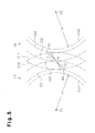
Fig. 5 is an enlarged view ofFig. 4 illustrating involute curves; -
Fig. 6 is an enlarged view ofFig. 5 illustrating involute curves and second trochoidal curves; -
Fig. 7 is a diagrammatic view illustrating first trochoidal curves; -
Fig. 8(a) is a diagrammatic view showing the first curved portions that are engaged with each other; -
Fig. 8(b) is an enlarged view showing the second curved portions that are engaged with each other; -
Figs. 9(a), 9(b), and 9(c) are cross-sectional views perpendicular to the axes of the rotors, showing examples of a tooth profile of a first screw rotor and a tooth profile of a second screw rotor; -
Figs. 9(d), 9(e), and 9(f) are cross-sectional views showing comparative examples of a tooth profile of a first conventional screw rotor and a tooth profile of a second conventional screw rotor, as viewed perpendicularly to the axes of the rotors; -
Fig. 10(a) is a cross-sectional view showing a tooth profile of a first screw rotor and a tooth profile of a second screw rotor according to a second embodiment of the present invention; -
Fig. 10(b) is a cross-sectional view showing a portion ofFig. 10(a) ; and -
Fig. 11 is a cross-sectional view showing a pair of conventional screw rotors as viewed perpendicularly to the axes of the rotors. -
Figs. 1 to 9 illustrate a first embodiment of the present invention. -
Fig. 1 shows ascrew pump 11 according to the first embodiment. Thescrew pump 11 operates to transport gas, which is fluid. As shown inFig. 1 , the housing of thescrew pump 11 includes arotor housing member 12, afront housing member 13, and arear housing member 14. Thefront housing member 13 shaped like a lid is joined with the front end (left end as viewed in the drawing) of therotor housing member 12 with a cylindrical shape. Therear housing member 14 shaped like a plate is joined with the rear end (right end as viewed in the drawing) of therotor housing member 12. Therear housing member 14 has a stepped securinghole 14a. Ashaft receiving body 15 is passed through the securinghole 14a and fastened to therear housing member 14 using a bolt. Theshaft receiving body 15 has a firstcylindrical portion 160 and a secondcylindrical portion 161, which extend parallel with each other in a forward direction. The first and secondcylindrical portions rotor housing member 12. - The first
cylindrical portion 160 has afirst support hole 190 and the secondcylindrical portion 161 has asecond support hole 191. Thefirst support hole 190 and thesecond support hole 191 each extend through theshaft receiving body 15. Adrive shaft 20 is received in thefirst support hole 190 and a drivenshaft 21 is arranged in thesecond support hole 191. A pair offirst roller bearings 240 support thedrive shaft 20 in a manner rotatable with respect to theshaft receiving body 15. A pair ofsecond roller bearings 241 support the drivenshaft 21 in a manner rotatable with respect to theshaft receiving body 15. The axis of the firstcylindrical portion 160 coincides with afirst axis 171, which is the rotary axis of thedrive shaft 20. The axis of the secondcylindrical portion 161 coincides with asecond axis 181, which is the rotary axis of the drivenshaft 21. The front end of thedrive shaft 20 and the front end of the driven shaft 21 (left end as viewed inFig. 1 ) project from thefirst support hole 190 and thesecond support hole 191, respectively. - The
rotor housing member 12 accommodates afirst screw rotor 17 and asecond screw rotor 18. The front end (left end as viewed inFig. 1 ) of thefirst screw rotor 17 is fixed to the front end of thedrive shaft 20 through ajoint plate 23 using a bolt. The front end of thesecond screw rotor 18 is fixed to the front end of the drivenshaft 21 through anotherjoint plate 23 using a bolt. Thus, thefirst screw rotor 17 rotates integrally with thedrive shaft 20 and thesecond screw rotor 18 rotates integrally with the drivenshaft 21. Thefirst screw rotor 17 is rotated in a first rotational direction X and thesecond screw rotor 18 is rotated in a second rotational direction Z. The first rotational direction X and the second rotational direction Z are opposite to each other. InFig. 2 , the first rotational direction X is a counterclockwise direction and the second rotational direction Z is a clockwise direction. - The
first screw rotor 17 and thesecond screw rotor 18 are screw gears each serving as a fluid transport body. Specifically, adrive tooth 17A is formed in thefirst screw rotor 17 and a driventooth 18A is provided in thesecond screw rotor 18. Thefirst screw rotor 17 includes adrive screw groove 17a, which extends between adjacent portions of thedrive tooth 17A. Thesecond screw rotor 18 includes a drivenscrew groove 18a, which extends between adjacent portions of the driventooth 18A. The axial direction of thefirst screw rotor 17 is to the direction of thefirst axis 171, which is the rotary axis of thefirst screw rotor 17. The axial direction of thesecond screw rotor 18 is to the direction of thesecond axis 181, which is the rotary axis of thesecond screw rotor 18. - The
first screw rotor 17 and thesecond screw rotor 18 are received in therotor housing member 12 in such a manner that thedrive tooth 17A and the driventooth 18A are arranged in the drivenscrew groove 18a and thedrive screw groove 17a, respectively. In other words, thefirst screw rotor 17 and thesecond screw rotor 18 are configured in such a manner as to provide a sealed space between thescrew rotors Pump chambers 10 each shaped like a figure eight are defined between each of the first andsecond screw rotors circumferential surface 121 of therotor housing member 12. - The thickness of the
drive tooth 17A decreases gradually from the front end (left end as viewed inFig. 1 ) of thefirst screw rotor 17 toward the rear end (right end as viewed in the drawing) and becomes uniform in the vicinity of the rear end. Similarly, the thickness of the driventooth 18A decreases gradually from the front end (left end as viewed inFig. 1 ) of thesecond screw rotor 18 toward the rear end (right end as viewed in the drawing) and becomes uniform in the vicinity of the rear end. In other words, the interval of thedrive tooth 17A, or the width of thedrive screw groove 17a, decreases gradually from the front end of thefirst screw rotor 17 toward the rear end and becomes uniform in the vicinity of the rear end. Likewise, the interval of the driventooth 18A, or the width of the drivenscrew groove 18a, decreases gradually from the front end of thesecond screw rotor 18 toward the rear end and becomes uniform in the vicinity of the rear end. - A
gear housing member 22 having a lidded cylindrical shape is joined with and fixed to the rear end of therear housing member 14. Arear end 20a of thedrive shaft 20 and arear end 21a of the driven shaft 21 (right end as viewed inFig. 1 ) project into the interior of thegear housing member 22. A pair of timing gears 25 are secured to therear ends electric motor 26, which is a drive source, is secured to thegear housing member 22. Anoutput shaft 26a of theelectric motor 26 is connected to therear end 20a of thedrive shaft 20 through ashaft coupling 27. - An
inlet port 28 is defined in the center of thefront housing member 13. Anoutlet port 29 is provided in the rear end of therotor housing member 12. Theinlet port 28 and theoutlet port 29 each communicate with thepump chambers 10. - As the
electric motor 26 runs, thedrive shaft 20 is rotated through theoutput shaft 26a and theshaft coupling 27. This causes the drivenshaft 21 to rotate in the direction different from the rotational direction of thedrive shaft 20 through engagement and connection between the two timing gears 25. In other words, thefirst screw rotor 17 and thesecond screw rotor 18 also rotate, drawing gas into thepump chambers 10 through theinlet port 28. The gas is then sent to theoutlet port 29 and discharged to the exterior of thepump chambers 10 through theoutlet port 29. - The tooth profile of the
first screw rotor 17 and that of thesecond screw rotor 18 will hereafter be explained in detail. -
Fig. 3 shows a cross section of the tooth profile of thefirst screw rotor 17 perpendicular to the rotor axis and that of thesecond screw rotor 18. The cross section of the tooth profile of thefirst screw rotor 17 perpendicular to the rotor axis corresponds to a cross-sectional shape of the tooth profile of thefirst screw rotor 17 on an imaginary plane perpendicular to the axial direction of thefirst screw rotor 17. The cross section of tooth profile of thesecond screw rotor 18 perpendicular to the rotor axis is shaped and sized equally with that of thefirst screw rotor 17. - With reference to
Fig. 3 , the sign L, which is the distance between thefirst axis 171 and thesecond axis 181, refers to an inter-pitch distance L between thedrive shaft 20 and the drivenshaft 21. As illustrated in the drawing, the distance between a first midpoint P1 on thefirst axis 171 and a second midpoint P2 on thesecond axis 181 coincides with the inter-pitch distance L. - The cross section of the tooth profile of the
first screw rotor 17 perpendicular to the rotor axis includes a drive tooth top arc A1B1, a drive tooth bottom arc C1D1, a first drive curve A1C1, and a second drive curve B1D1. The drive tooth top arc A1B1 is a first circular arc portion extending from a first end A1 to a second end B1 about the first midpoint P1. The drive tooth bottom arc C1D1 is a second circular arc portion extending from a first end C1 to a second end D1 about the first midpoint P1. The first drive curve A1C1 is a first curved portion that connects the first end A1 of the drive tooth top arc A1B1 to the first end C1 of the drive tooth bottom arc C1D1. The second drive curve B1D1 is a second curved portion that connects the second end B1 of the drive tooth top arc A1B1 to the second end D1 of the drive tooth bottom arc C1D1. - The first midpoint P1 is arranged between the drive tooth top arc A1B1 and the drive tooth bottom arc C1D1. The first end A1 and the first end C1 are located on the same side (left side as viewed in
Fig. 2(a) ) while the second end B1 and the second end D1 are arranged on the opposite side (right side as viewed in the drawing), with respect to the first midpoint P1. The radius of curvature (R2) of the drive tooth bottom arc C1D1 is smaller than the radius of curvature (R1) of the drive tooth top arc A1B1. - With reference to
Fig. 3 , the cross section of the tooth profile of thesecond screw rotor 18 perpendicular to the rotor axis includes a driven tooth top arc A2B2, a driven tooth bottom arc C2D2, a first driven curve A2C2, and a second driven curve B2D2. The driven tooth top arc A2B2 is a first circular arc portion extending from a first end A2 to a second end B2 about the second midpoint P2. The driven tooth bottom arc C2D2 is a second circular arc portion extending from a first end C2 to a second end D2 about the second midpoint P2. The first driven curve A2C2 is a first curved portion that connects the first end A2 of the driven tooth top arc A2B2 to the first end C2 of the driven tooth bottom arc C2D2. The second driven curve B2D2 is a second curved portion that connects the second end B2 of the driven tooth top arc A2B2 to the second end D2 of the driven tooth bottom arc C2D2. - The second midpoint P2 is arranged between the driven tooth top arc A2B2 and the driven tooth bottom arc C2D2. The first end A2 and the first end C2 are located on the same side (right side as viewed in
Fig. 2(a) ) while the second end B2 and the second end D2 are arranged on the opposite side (left side as viewed in the drawing) with respect to the second midpoint P2. The radius of curvature (R2) of the driven tooth bottom arc C2D2 is smaller than the radius of curvature (R1) of the driven tooth top arc A2B2. -
Fig. 3 illustrates an imaginary straight line M that includes the first midpoint P1 and the second midpoint P2. The first end A1 of the drive tooth top arc A1B1 and the first end A2 of the driven tooth top arc A2B2 are located on the imaginary straight line M. The first drive curve A1C1 is a trochoidal curve (a first drive trochoidal curve) created by the path of the first end A2 of the driven tooth top arc A2B2. The first driven curve A2C2 is a trochoidal curve (a first driven trochoidal curve) created by the path of the first end A1 of the drive tooth top arc A1B1. - The second drive curve B1D1 is a composite curve formed by a drive involute curve B1E1 and a second drive trochoidal curve E1D1 that extend continuously from each other at a first intersection point E1. The drive involute curve B1E1 extends continuously from the second end B1 of the drive tooth top arc A1B1. The second drive trochoidal curve E1D1 extends continuously from the second end D1 of the drive tooth bottom arc C1D1.
- Similarly, the second driven curve B2D2 is a composite curve formed by a driven involute curve B2E2 and a second driven trochoidal curve E2D2 that extend continuously from each other at a second intersection point E2. The driven involute curve B2E2 extends continuously from the second end B2 of the driven tooth top arc A2B2. The second driven trochoidal curve E2D2 extends continuously from the second end D2 of the driven tooth bottom arc C2D2.
- The drive involute curve B1E1 is defined by a first base circle Co1, which is illustrated in
Fig. 4 . The center of the first base circle Co1 is the first midpoint P1. An involute radius Ro, which is the radius of the first base circle Co1, is smaller than a pitch radius r = L/2, which is a half of the inter-pitch distance L (Ro < r). The driven involute curve B2E2 is defined by a second base circle Co2, which is illustrated inFig. 4 . The center of the second base circle Co2 is the second midpoint P2. The second base circle Co2 has the involute radius Ro with respect to the second midpoint P2. - The second drive trochoidal curve E1D1 is created by the path of the second end B2 of the driven tooth top arc A2B2. The second driven trochoidal curve E2D2 is created by the path of the second end B1 of the drive tooth top arc A1B1.
- As illustrated in
Fig. 3 , the angle of the drive tooth top arc A1B1 about the first midpoint P1 and the angle of the driven tooth top arc A2B2 about the second midpoint P2 are each referred to as a first angle θ1. The angle of the drive tooth bottom arc C1D1 about the first midpoint P1 and the angle of the driven tooth bottom arc C2D2 about the second midpoint P2 are each referred to as a second angle θ2. In the first embodiment, the first angle θ1 of the drive tooth top arc A1B1 is equal to the first angle θ1 of the driven tooth top arc A2B2. Also, the second angle θ2 of the drive tooth bottom arc C1D1 is equal to the second angle θ2 of the driven tooth bottom arc C2D2. In the first embodiment, the first angle θ1 and the second angle θ2 are both less than 180 degrees (θ1 < 180°, θ2 < 180°). The first angle θ1 is set equal to the second angle θ2 (θ1 = θ2). - As shown in
Fig. 2(c) , thefirst screw rotor 17 has a drive toothtop surface 172, which is the tooth top surface of thedrive tooth 17A, and a drive toothbottom surface 173, which is the tooth bottom surface of thedrive screw groove 17a. A cross section of the drive toothtop surface 172 perpendicular to the rotor axis is the drive tooth top arc A1B1. A cross section of the drive toothbottom surface 173 perpendicular to the rotor axis is the drive tooth bottom arc C1D1. The drive toothtop surface 172 and the drive toothbottom surface 173 are circumferential surfaces that extend spirally along thefirst axis 171. - Similarly, the
second screw rotor 18 has a driven toothtop surface 182, which is the tooth top surface of the driventooth 18A, and a driven toothbottom surface 183, which is the tooth bottom surface of the drivenscrew groove 18a. A cross section of the driven toothtop surface 182 perpendicular to the rotor axis is the driven tooth top arc A2B2. A cross section of the driven toothbottom surface 183 perpendicular to the rotor axis is the driven tooth bottom arc C2D2. The driven toothtop surface 182 and the driven toothbottom surface 183 are circumferential surfaces that extend spirally along thesecond axis 181. - If the first angle θ1 of the
first screw rotor 17 is equal to the second angle θ2, the axial dimension of the drive toothtop surface 172 is substantially equal to the axial dimension of the drive toothbottom surface 173. If the first angle θ1 of thesecond screw rotor 18 is equal to the second angle θ2, the axial dimension of the driven toothtop surface 182 is substantially equal to the axial dimension of the driven toothbottom surface 183. The axial dimension of the drive toothtop surface 172 is a dimension measured along thefirst axis 171 and the axial dimension of the driven toothtop surface 182 is a dimension measured along thesecond axis 181. - As illustrated in
Fig. 2(c) , thefirst screw rotor 17 has a drivetooth side surface 174, which is the side surface of thedrive tooth 17A, and thesecond screw rotor 18 has a driventooth side surface 184, which is the side surface of the driventooth 18A. The drivetooth side surface 174 is opposed to the driventooth side surface 184. A cross section of the drivetooth side surface 174 perpendicular to the rotor axis is the second drive curve B1D1. A cross section of the driventooth side surface 184 perpendicular to the rotor axis is the second driven curve B2D2. The drivetooth side surface 174 is a curved surface that connects the drive toothtop surface 172 to the drive toothbottom surface 173. The driventooth side surface 184 is a curved surface that connects the driven toothtop surface 182 to the driven toothbottom surface 183. Thefirst screw rotor 17 and thesecond screw rotor 18 rotate in a non-contact manner with each other. However, as the clearance between thefirst screw rotor 17 and thesecond screw rotor 18 becomes substantially eliminated, a linear seal portion is formed apparently. - With reference to
Fig. 2(c) , the angle between the drive toothtop surface 172 and the drivetooth side surface 174 is a drive tooth top angle α. The angle between the driven toothtop surface 182 and the driventooth side surface 184 is a driven tooth top angle β. The angle between the innercircumferential surface 121 of therotor housing member 12 and the drivetooth side surface 174 is a first clearance angle γ. The angle between the innercircumferential surface 121 of therotor housing member 12 and the driventooth side surface 184 is a second clearance angle δ. The drive tooth top angle α is an obtuse angle (an angle greater than 90° and smaller than 180°) and the first clearance angle γ is an acute angle (an angle less than 90°). The driven tooth top angle β is an obtuse angle and the second clearance angle 5 is an acute angle. In the first embodiment, the drive tooth top angle α is equal to the driven tooth top angle β (α = β). The first clearance angle γ is equal to the second clearance angle δ (γ = δ). - A procedure for forming the cross section of the tooth profile of the
first screw rotor 17 perpendicular to the rotor axis and the cross section of the tooth profile of thesecond screw rotor 18 perpendicular to the rotor axis will now be explained. - First, as illustrated in
Fig. 4 , the first midpoint P1, the second midpoint P2, and the inter-pitch distance L are determined. The circle about the first midpoint P1 with the pitch radius r is referred to as a first pitch circle C31. The circle about the second midpoint P2 with the pitch radius r is referred to as a second pitch circle C32. The pitch radius r is equal to L/2. That is, the first pitch circle C31 and the second pitch circle C32 contact each other at a contact point F, which is located at the midpoint between the first midpoint P1 and the second midpoint P2. - Then, the first outer circle C11 having an outer radius R1 greater than the pitch radius r and the first inner circle C21 with an inner radius R2 smaller than the pitch radius r are determined with respect to the first midpoint P1 (R2 < r < R1). Similarly, the second outer circle C12 with the outer radius R1 and the second inner circle C22 with the inner radius R2 are determined with respect to the second midpoint P2. The inter-pitch distance L is the sum of the outer radius R1 and the inner radius R2 (L = R1 + R2 = 2r).
- Subsequently, with reference to
Fig. 5 , the first base circle Co1 and the second base circle Co2 are determined. The involute radius Ro is set to a value less than the pitch radius r (Ro < r). Using the first base circle Co1, a created drive involute curve I1 is determined in such a manner that the created drive involute curve I1 includes the contact point F. The intersection point between the created drive involute curve I1 and the first outer circle C11 is the second end B1 of the drive tooth top arc A1B1. Likewise, using the second base circle Co2, a created driven involute curve I2 is determined in such a manner that the created driven involute curve I2 includes the contact point F. The intersection point between the created driven involute curve I2 and the second outer circle C12 is the second end B2 of the driven tooth top arc A2B2. - Next, as illustrated in
Fig. 6 , a second created drive trochoidal curve J1 is determined by the path of the second end B2 when thefirst screw rotor 17 and thesecond screw rotor 18 are rotated. In other words, a second created drive trochoidal curve J1 is created by revolution of thesecond screw rotor 18 around thefirst screw rotor 17 with the second pitch circle C32 held in contact with the first pitch circle C31. The intersection point between the second created drive trochoidal curve J1 and the first inner circle C21 is the second end D1 of the drive tooth bottom arc C1D1. The intersection point between the second created drive trochoidal curve J1 and the created drive involute curve I1 is the first intersection point E1. The second created drive trochoidal curve J1 is connected to the created drive involute curve I1 at the first intersection point E1. The portion of the created drive involute curve I1 between the second end B1 and the first intersection point E1 forms the drive involute curve B1E1. The portion of the second created drive trochoidal curve J1 between the first intersection point E1 and the second end D1 forms the second drive trochoidal curve E1D1. The tangential line of the drive involute curve B1E1 coincides with the tangential line of the second drive trochoidal curve E1D1 at the first intersection point E1. In other words, the first intersection point E1 is a connection point between the drive involute curve B1E1 and the second drive trochoidal curve E1D1. - Similarly, with reference to
Fig. 6 , a second created driven trochoidal curve J2 is determined by the path of the second end B1 when thefirst screw rotor 17 and thesecond screw rotor 18 are rotated. In other words, a second created driven trochoidal curve J2 is created by revolution of thefirst screw rotor 17 around thesecond screw rotor 18 with the first pitch circle C31 held in contact with the second pitch circle C32. The intersection point between the second created driven trochoidal curve J2 and the second inner circle C22 is the second end D2 of the driven tooth bottom arc C2D2. The intersection point between the second created driven trochoidal curve J2 and the created driven involute curve I2 is the second intersection point E2. The second created driven trochoidal curve J2 is connected to the created driven involute curve I2 at the second intersection point E2. The portion of the created driven involute curve I2 between the second end B2 and the second intersection point E2 forms the driven involute curve B2E2. The portion of the second created driven trochoidal curve J2 between the second intersection point E2 and the second end D2 forms the second driven trochoidal curve E2D2. The tangential line of the driven involute curve B2E2 coincides with the tangential line of the second driven trochoidal curve E2D2 at the second intersection point E2. In other words, the second intersection point E2 is a connection point between the driven involute curve B2E2 and the second driven trochoidal curve E2D2. - The imaginary straight line M including the first midpoint P1 and the second midpoint P2 is then determined as illustrated in
Fig. 7 . The intersection point between the imaginary straight line M and the first outer circle C11 outside the range between the first midpoint P1 and the second midpoint P2 is the first end A1 of the drive tooth top arc A1B1. In the same manner, the intersection point between the imaginary straight line M and the second outer circle C12 outside the range between the first midpoint P1 and the second midpoint P2 is the first end A2 of the driven tooth top arc A2B2. - As illustrated in
Fig. 7 , a first created drive trochoidal curve K1 is determined by the path of the first end A2 of thesecond screw rotor 18 when thefirst screw rotor 17 and thesecond screw rotor 18 are rotated. In other words, the first created drive trochoidal curve K1 is created by revolution of thesecond screw rotor 18 around thefirst screw rotor 17 with the second pitch circle C32 held in contact with the first pitch circle C31. The first created drive trochoidal curve K1 includes the first end A1 of thefirst screw rotor 17. The intersection point between the first created drive trochoidal curve K1 and the first inner circle C21 is the first end C1 of the drive tooth bottom arc C1D1. The portion of the first created drive trochoidal curve K1 between the first end A1 and the first end C1 forms the first drive curve A1C1. - Similarly, with reference to
Fig. 7 , a first created driven trochoidal curve K2 is determined by the path of the first end A1 of thefirst screw rotor 17 when thefirst screw rotor 17 and thesecond screw rotor 18 are rotated. In other words, the first created driven trochoidal curve K2 is created by revolution of thefirst screw rotor 17 around thesecond screw rotor 18 with the first pitch circle C31 held in contact with the second pitch circle C32. The first created driven trochoidal curve K2 includes the first end A2 of thesecond screw rotor 18. The intersection point between the first created driven trochoidal curve K2 and the second inner circle C22 is the first end C2 of the driven tooth bottom arc C2D2. The portion of the first created driven trochoidal curve K2 between the first end A2 and the first end C2 forms the first driven curve A2C2. - The portion of the first outer circle C11 between the first end A1 and the second end B1 forms the drive tooth top arc A1B1. The drive tooth top arc A1B1 is determined in such a manner that an acute angle is formed between the drive tooth top arc A1B1 and the first drive curve A1C1. The portion of the first inner circle C21 between the first end C1 and the second end D1 forms the drive tooth bottom arc C1D1. The drive tooth bottom arc C1D1 is determined in such a manner that the first midpoint P1 is provided between the drive tooth top arc A1B1 and the drive tooth bottom arc C1D1. The radius of curvature of the drive tooth top arc A1B1 is the outer radius R1 and the radius of curvature of the drive tooth bottom arc C1D1 is the inner radius R2.
- In the same manner, the portion of the second outer circle C12 between the first end A2 and the second end B2 forms the driven tooth top arc A2B2. The driven tooth top arc A2B2 is determined in such a manner that an acute angle is formed between the driven tooth top arc A2B2 and the first driven curve A2C2. The portion of the second inner circle C22 between the first end C2 and the second end D2 forms the driven tooth bottom arc C2D2. The driven tooth bottom arc C2D2 is determined in such a manner that the second midpoint P2 is provided between the driven tooth top arc A2B2 and the driven tooth bottom arc C2D2.
- In this manner, the procedure for forming the cross sections of the tooth profiles of the
first screw rotor 17 and thesecond screw rotor 18 perpendicular to the respective rotor axes is accomplished. - As the
first screw rotor 17 of thescrew pump 11 continuously rotates in the first rotational direction X and thesecond screw rotor 18 continuously rotates in the second rotational direction Z, the first end A2 of thesecond screw rotor 18 moves along the first drive curve A1C1, as illustrated inFig. 8(a) . The first end A1 of thefirst screw rotor 17 then moves along the first driven curve A2C2. - As the
first screw rotor 17 and thesecond screw rotor 18 continuously rotate, the second end B1 of thefirst screw rotor 17 moves along the second driven trochoidal curve E2D2. The drive involute curve B1E1 then becomes engaged with the driven involute curve B2E2. Afterwards, with reference toFig. 8(b) , the second end B2 of thesecond screw rotor 18 moves along the second drive trochoidal curve E1D1. -
Fig. 9(a), Fig. 9(b), and Fig. 9(c) show a first example, a second example, and a third example, respectively, of the tooth profiles of thefirst screw rotor 17 and thesecond screw rotor 18 according to the present invention.Fig. 9(d), Fig. 9(e), and Fig. 9(f) show a first comparative example, a second comparative example, and a third comparative example, respectively, of the tooth profiles of the first and secondconventional screw rotors Fig. 11 . Commonly inFigs. 9(a) to 9(f) , the pitch radius r, the outer radius R1, and the inner radius R2 are set to 40 mm, 55.5 mm, and 24.5 mm, respectively. - In
Figs. 9(a) and 9(d) , the involute radius Ro is smaller than the inner radius R2 (Ro < R2), and Ro is set to 16.75 mm. InFigs. 9(b) and 9(e) , the involute radius Ro is equal to the inner radius R2 (Ro = R2), and Ro is set to 24.5 mm. InFigs. 9(c) and 9(f) , the involute radius Ro is greater than the inner radius R2 and smaller than the pitch radius r (R2 < Ro < r), and Ro is set to 32.25 mm. - In the first example shown in
Fig. 9(a) , in which Ro is 16.75 mm, the equation: θ1 = θ2 = 130.67° is satisfied. In the first comparative example shown inFig. 9(d) , in which Ro is 16.75 mm, the equation: θ1 = θ2 = 126.9° is satisfied. - In the second example shown in
Fig. 9(b) , in which Ro is 24.5 mm, the equation: θ1 = θ2 = 149.43° is satisfied. In the second comparative example shown inFig. 9(e) , in which Ro is 24.5 mm, the equation: θ1 = θ2 = 143.85° is satisfied. - In the third example shown in
Fig. 9(c) , in which Ro is 32.25 mm, the equation: θ1 = θ2 = 160° is satisfied. In the third comparative example shown inFig. 9(f) , in which Ro is 32.25 mm, the equation: θ1 = θ2 = 152.68° is satisfied. - As is clear from comparison between the first example of
Fig. 9(a) and the first comparative example ofFig. 9(d) , when the involute radius Ro is smaller than the inner radius R2 (Ro < R2), the values θ1 and θ2 of thefirst screw rotor 17 and thesecond screw rotor 18 are greater than the values θ1 and θ2 of the first and secondconventional screw rotors - As is clear from comparison between the second example of
Fig. 9(b) and the second comparative example ofFig. 9(e) , when the involute radius Ro is equal to the inner radius R2 (Ro = R2), the values θ1 and θ2 of thefirst screw rotor 17 and thesecond screw rotor 18 are greater than the values θ1 and θ2 of the first and secondconventional screw rotors - As is clear from comparison between the third example of
Fig. 9(c) and the third comparative example ofFig. 9(f) , when the involute radius Ro is greater than the inner radius R2 and smaller than the pitch radius r (R2 < Ro < r), the values θ1 and θ2 of thefirst screw rotor 17 and thesecond screw rotor 18 are greater than the values θ1 and θ2 of the first and secondconventional screw rotors - In other words, when the involute radius Ro is smaller than the pitch radius r (Ro < r), the values θ1 and θ2 of the first and
second screw rotors conventional screw rotors - The first embodiment has the following advantages.
- (1) The second drive curve B1D1 is the composite curve formed by the drive involute curve B1E1 and the second drive trochoidal curve E1D1. The second driven curve B2D2 is the composite curve formed by the driven involute curve B2E2 and the second driven trochoidal curve E2D2. In contrast, a second conventional drive curve T1R1, which is illustrated in
Fig. 11 , is a composite curve formed by an outer circular arc R1W1, an involute curve W1Y1, and an inner circular arc Y1T1. As a result, in the first embodiment, the length of the second drive curve B1D1 and the length of the second driven curve B2D2 are decreased compared to the conventional case. This increases the circumferential dimension of the drive tooth top arc A1B1, or the first angle θ1, and the circumferential dimension of the drive tooth bottom arc C1D1, or the second angle θ2. Also, the circumferential dimension of the driven tooth top arc A2B2, or the first angle θ1, and the circumferential dimension of the driven tooth bottom arc C2D2, or the second angle θ2, are increased.
As the circumferential dimension of the drive tooth top arc A1B1 increases, the axial dimension of the drive toothtop surface 172 increases. This increases the seal length between the drive toothtop surface 172 and the innercircumferential surface 121 of therotor housing member 12. Thus, leakage of fluid between adjacent ones of thepump chambers 10 is effectively suppressed. Further, as the circumferential dimension of the driven tooth top arc A2B2 increases, the axial dimension of the driven toothtop surface 182 increases. The seal length between the driven toothtop surface 182 and the innercircumferential surface 121 of therotor housing member 12 is thus increased. This effectively suppresses the leakage of the fluid between adjacent ones of thepump chambers 10. - (2) As the circumferential dimension of the drive tooth bottom arc C1D1 increases, the axial dimension of the drive tooth
bottom surface 173 increases. This facilitates machining of thedrive screw groove 17a. Also, as the circumferential dimension of the driven tooth bottom arc C2D2 increases, the axial dimension of the driven toothbottom surface 183 increases. This facilitates machining of the drivenscrew groove 18a. - (3) The drive
tooth side surface 174 of thefirst screw rotor 17 is opposed to the driventooth side surface 184 of thesecond screw rotor 18. The angle between the drivetooth side surface 174 and the drive toothtop surface 172 is the drive tooth top angle α. The angle between the driventooth side surface 184 and the driven toothtop surface 182 is the driven tooth top angle β. The drivetooth side surface 174 of thefirst screw rotor 17 is created by the second driven curve B2D2, which is the composite curve formed by the driven involute curve B2E2 and the second driven trochoidal curve E2D2. In contrast, the drive tooth side surface of the firstconventional screw rotor 90A, which is shown inFig. 11 , is created by the second curve T2R2, which is the composite curve formed by the outer circular arc R2W2, the involute curve W2Y2, and the inner circular arc Y2T2. Thus, in the first embodiment, the drive tooth top angle α becomes smaller than that of the conventional case. In other words, in this embodiment, the first clearance angle γ becomes greater than that of the conventional case. That is, the first clearance angle γ becomes wider than that of the conventional case. As a result, in this embodiment, foreign objects such as a reaction product contained in the fluid (the gas) transported through operation of thescrew pump 11 are prevented from entering the gap between the innercircumferential surface 121 of therotor housing member 12 and the drive toothtop surface 172.
Similarly, the driventooth side surface 184 of thesecond screw rotor 18 is created by the second drive curve B1D1, which is the composite curve formed by the drive involute curve B1E1 and the second drive trochoidal curve E1D1. In contrast, the driven tooth side surface of the secondconventional screw rotor 90B, which is shown inFig. 11 , is created by the second curve T1R1, which is the composite curve formed by the outer circular arc R1W1, the involute curve W1Y1, and the inner circular arc Y1T1. Thus, in the first embodiment, the driven tooth top angle β becomes smaller than that of the conventional case and the second clearance angle δ becomes greater than that of the conventional case. That is, the second clearance angle δ becomes wider than that of the conventional case. As a result, in this embodiment, the foreign objects contained in the fluid that is being transported are prevented from entering the gap between the innercircumferential surface 121 of therotor housing member 12 and the driven toothtop surface 182. - (4) The second driven curve B2D2, which is the composite curve formed by the driven involute curve B2E2 and the second driven trochoidal curve E2D2, forms the drive
tooth side surface 174. The second drive curve B1D1, which is the composite curve formed by the drive involute curve B1E1 and the second drive trochoidal curve E1D1, forms the driventooth side surface 184. This enlarges the clearance around the linear seal portion created between the drivetooth side surface 174 and the driventooth side surface 184 in the vicinity of the drive toothbottom surface 173 and the vicinity of the driven toothbottom surface 183. Thus, thescrew pump 11 is further effectively prevented from catching foreign objects. - For example, the involute curve W1Y1 illustrated in
Fig. 11 is indirectly connected to the tooth top arc Q1R1 through the outer circular arc R1W1. This arrangement causes the foreign objects to be easily collected in an area from the clearance near the tooth bottom surface to the seal portion between the tooth top surface and the tooth bottom surface. The foreign obstacles are thus easily caught. However, in the first embodiment, this problem is solved. - The first embodiment may be modified as follows.
- The thickness (the axial dimension) of the
drive tooth 17A may be uniform from the front end to the rear end of thefirst screw rotor 17, instead of decreasing from the front end to the rear end of thefirst screw rotor 17. Similarly, the thickness of the driventooth 18A may be uniform from the front end to the rear end of thesecond screw rotor 18. - The number of the
drive teeth 17A of thefirst screw rotor 17 and the number of the driventeeth 18A of thesecond screw rotor 18 are not restricted to one but may be two. - The first angle θ1 and the second angle θ2 may be altered as needed. For example, as in a second embodiment shown in
Fig. 10(a) , the first angle θ1 of thefirst screw rotor 17 may be greater than the second angle θ2. That is, the first angle θ1 may be set to a value greater than 180° while the second angle θ2 is set to a value smaller than 180°. The circumferential dimension of the drive tooth top arc A1B1 is greater than the circumferential dimension of the driven tooth bottom arc C2D2. The first angle θ1 of thesecond screw rotor 18 is set to a value smaller than the second angle θ2. In other words, the circumferential dimension of the driven tooth top arc A2B2 is set to a value smaller than the circumferential dimension of the driven tooth bottom arc C2D2. In this case, with reference toFig. 10(b) , the axial dimension of thedrive tooth 17A is greater than the axial dimension of the driventooth 18A. The width (the axial dimension) of thedrive screw groove 17a is smaller than the width of the drivenscrew groove 18a.
Claims (3)
- A screw pump comprising:a housing; anda first screw rotor and a second screw rotor received in the housing, wherein the first screw rotor and the second screw rotor rotate in a direction in which the first and second screw rotors become engaged with each other, a fluid being drawn into the housing and then discharged to the exterior through rotation of the first screw rotor and the second screw rotor,the screw pump being characterized in that a cross section of a tooth profile of the first screw rotor and a cross section of a tooth profile of the second screw rotor perpendicular to the respective rotor axes each include a first circular arc portion, a second circular arc portion, a first curved portion, and a second curved portion, the first circular arc portion and the second circular arc portion each having a first end and a second end, the radius of curvature of the second circular arc portion being smaller than the radius of curvature of the first circular arc portion, the first curved portion connecting the first end of the first circular arc portion to the first end of the second circular arc portion, the second curved portion connecting the second end of the first circular arc portion to the second end of the second circular arc portion,wherein the first curved portion of the first screw rotor is a first trochoidal curve created by the first end of the first circular arc portion of the second screw rotor,wherein the second curved portion of the first screw rotor includes an involute curve and a second trochoidal curve that extend continuously from each other, the involute curve extending continuously from the second end of the first circular arc portion of the first screw rotor, the second trochoidal curve being created by the second end of the first circular arc portion of the second screw rotor,wherein the first curved portion of the second screw rotor is a first trochoidal curve created by the first end of the first circular arc portion of the first screw rotor, andwherein the second curved portion of the second screw rotor includes an involute curve and a second trochoidal curve that extend continuously from each other, the involute curve extending continuously from the second end of the first circular arc portion of the second screw rotor, the second trochoidal curve being created by the second end of the first circular arc portion of the first screw rotor.
- The screw pump according to claim 1, characterized in that the rotary axis of the first screw rotor is referred to as a first axis, and the rotary axis of the second screw rotor is referred to as a second axis,
wherein the angle of the first circular arc portion of the first screw rotor with respect to the first axis, the angle of the second circular arc portion of the first screw rotor with respect to the first axis, the angle of the first circular arc portion of the second screw rotor with respect to the second axis, and the angle of the second circular arc portion of the second screw rotor with respect to the second axis are all equal. - A screw rotor of a screw pump, the screw rotor being one of a first screw rotor and a second screw rotor, the first screw rotor and the second screw rotor being accommodated in a housing of the screw pump, the first screw rotor and the second screw rotor rotating in a direction in which the first and second screw rotors become engaged with each other, thereby drawing a fluid into the housing and then discharging the fluid to the exterior of the housing,
the screw rotor being characterized in that:a cross section of a tooth profile of the first screw rotor and a cross section of a tooth profile of the second screw rotor perpendicular to the respective rotor axes each include a first circular arc portion, a second circular arc portion, a first curved portion, and a second curved portion, the first circular arc portion and the second circular arc portion each having a first end and a second end, the radius of curvature of the second circular arc portion being smaller than the radius of curvature of the first circular arc portion, the first curved portion connecting the first end of the first circular arc portion to the first end of the second circular arc portion, the second curved portion connecting the second end of the first circular arc portion to the second end of the second circular arc portion,wherein the first curved portion of the first screw rotor is a first trochoidal curve created by the first end of the first circular arc portion of the second screw rotor,wherein the second curved portion of the first screw rotor includes an involute curve and a second trochoidal curve that extend continuously from each other, the involute curve extending continuously from the second end of the first circular arc portion of the first screw rotor, the second trochoidal curve being created by the second end of the first circular arc portion of the second screw rotor,wherein the first curved portion of the second screw rotor is a first trochoidal curve created by the first end of the first circular arc portion of the first screw rotor, andwherein the second curved portion of the second screw rotor includes an involute curve and a second trochoidal curve that extend continuously from each other, the involute curve extending continuously from the second end of the first circular arc portion of the second screw rotor, the second trochoidal curve being created by the second end of the first circular arc portion of the first screw rotor.
Applications Claiming Priority (2)
| Application Number | Priority Date | Filing Date | Title |
|---|---|---|---|
| JP2006240042 | 2006-09-05 | ||
| PCT/JP2007/067125 WO2008029759A1 (en) | 2006-09-05 | 2007-09-03 | Screw pump and screw rotor |
Publications (2)
| Publication Number | Publication Date |
|---|---|
| EP2060789A1 true EP2060789A1 (en) | 2009-05-20 |
| EP2060789A4 EP2060789A4 (en) | 2013-08-28 |
Family
ID=39157186
Family Applications (1)
| Application Number | Title | Priority Date | Filing Date |
|---|---|---|---|
| EP07806598.4A Withdrawn EP2060789A4 (en) | 2006-09-05 | 2007-09-03 | Screw pump and screw rotor |
Country Status (6)
| Country | Link |
|---|---|
| US (1) | US7798794B2 (en) |
| EP (1) | EP2060789A4 (en) |
| JP (1) | JP4893630B2 (en) |
| KR (1) | KR100976112B1 (en) |
| TW (1) | TWI336373B (en) |
| WO (1) | WO2008029759A1 (en) |
Cited By (6)
| Publication number | Priority date | Publication date | Assignee | Title |
|---|---|---|---|---|
| EP2148046A2 (en) | 2008-07-23 | 2010-01-27 | United Technologies Corporation | Actuated variable geometry mid turbine frame design |
| CN103195716A (en) * | 2013-05-07 | 2013-07-10 | 巫修海 | Novel tooth-shaped screw type wire |
| EP2295801A3 (en) * | 2009-07-22 | 2015-06-24 | Kabushiki Kaisha Toyota Jidoshokki | Screw pump rotor |
| CN104776027A (en) * | 2013-04-26 | 2015-07-15 | 巫修海 | Screw rotor profile line of strictly-sealed dry screw vacuum pump |
| CN105697363A (en) * | 2016-03-11 | 2016-06-22 | 天津华科螺杆泵技术有限公司 | Asymmetric-tooth-shaped two-end spiral screw with involute force transmission side |
| CN107084131A (en) * | 2017-06-08 | 2017-08-22 | 中国石油大学(华东) | A kind of complete smooth screw rotor based on eccentric circle involute |
Families Citing this family (8)
| Publication number | Priority date | Publication date | Assignee | Title |
|---|---|---|---|---|
| IT1396898B1 (en) * | 2008-12-02 | 2012-12-20 | Marzocchi Pompe S P A | TOOTHED PROFILE FOR VOLUMETRIC PUMP ROTORS WITH EXTERNAL GEARS. |
| CN105317677B (en) * | 2015-11-09 | 2017-10-24 | 中国石油大学(华东) | A kind of screw rotor without acute angle cusp |
| CN105240277B (en) * | 2015-11-09 | 2017-05-03 | 中国石油大学(华东) | Fully-smooth screw rotor of twin-screw vacuum pump |
| CN105332914B (en) * | 2015-11-09 | 2017-05-31 | 中国石油大学(华东) | A kind of complete smooth screw rotor |
| CN108223360B (en) * | 2018-02-28 | 2024-05-07 | 上海诺科泵业有限公司 | Asymmetric screw rotor, method for generating end surface molded line of asymmetric screw rotor and double-screw pump |
| CN108443145B (en) * | 2018-05-22 | 2020-04-21 | 天津华科螺杆泵技术有限公司 | Double-end spiral screw, double-screw pump adopting same and dry vacuum screw pump |
| CN109854504B (en) * | 2019-04-02 | 2020-03-24 | 萨震压缩机(上海)有限公司 | Energy-saving screw molded line |
| CN113638880B (en) * | 2021-09-06 | 2023-03-21 | 台州学院 | Screw vacuum pump and screw rotor thereof |
Family Cites Families (13)
| Publication number | Priority date | Publication date | Assignee | Title |
|---|---|---|---|---|
| GB112104A (en) * | 1917-07-05 | 1917-12-27 | Edward Nuebling | Improvements in or relating to Rotary Meters, Pumps and Motors. |
| US2994562A (en) * | 1959-02-05 | 1961-08-01 | Warren Pumps Inc | Rotary screw pumping of thick fibrous liquid suspensions |
| JPS5746083A (en) | 1980-09-01 | 1982-03-16 | Shigeyoshi Osada | Improved quimby pump |
| US4792294A (en) * | 1986-04-11 | 1988-12-20 | Mowli John C | Two-stage screw auger pumping apparatus |
| AT400693B (en) * | 1994-05-17 | 1996-02-26 | Hladik Herta | RINGBOOK MECHANICS |
| KR0133154B1 (en) * | 1994-08-22 | 1998-04-20 | 이종대 | Screw pump |
| JP2904719B2 (en) | 1995-04-05 | 1999-06-14 | 株式会社荏原製作所 | Screw rotor, method for determining cross-sectional shape of tooth profile perpendicular to axis, and screw machine |
| JP3831110B2 (en) * | 1998-03-25 | 2006-10-11 | 大晃機械工業株式会社 | Vacuum pump screw rotor |
| ATE266800T1 (en) * | 1998-10-23 | 2004-05-15 | Busch Sa Atel | TWIN CONVEYOR SCREW ROTORS |
| CN1337528A (en) * | 2001-09-12 | 2002-02-27 | 浙江大学 | New profile bolt |
| JPWO2005113984A1 (en) | 2004-05-24 | 2008-03-27 | ナブテスコ株式会社 | Screw rotor and screw fluid machine |
| JP4068083B2 (en) | 2004-06-14 | 2008-03-26 | 神港精機株式会社 | Screw rotor |
| AU2005327862B2 (en) * | 2005-02-16 | 2011-06-02 | Ateliers Busch Sa | Volumetric rotary machine with rotors having asymmetric profiles |
-
2007
- 2007-09-03 WO PCT/JP2007/067125 patent/WO2008029759A1/en not_active Ceased
- 2007-09-03 KR KR1020087007874A patent/KR100976112B1/en not_active Expired - Fee Related
- 2007-09-03 US US11/992,700 patent/US7798794B2/en not_active Expired - Fee Related
- 2007-09-03 EP EP07806598.4A patent/EP2060789A4/en not_active Withdrawn
- 2007-09-03 JP JP2007553400A patent/JP4893630B2/en not_active Expired - Fee Related
- 2007-09-05 TW TW096133020A patent/TWI336373B/en not_active IP Right Cessation
Cited By (9)
| Publication number | Priority date | Publication date | Assignee | Title |
|---|---|---|---|---|
| EP2148046A2 (en) | 2008-07-23 | 2010-01-27 | United Technologies Corporation | Actuated variable geometry mid turbine frame design |
| EP2295801A3 (en) * | 2009-07-22 | 2015-06-24 | Kabushiki Kaisha Toyota Jidoshokki | Screw pump rotor |
| CN104776027A (en) * | 2013-04-26 | 2015-07-15 | 巫修海 | Screw rotor profile line of strictly-sealed dry screw vacuum pump |
| CN104776027B (en) * | 2013-04-26 | 2016-10-26 | 巫修海 | Strict seal type dry screw vacuum pump screw rotor |
| CN103195716A (en) * | 2013-05-07 | 2013-07-10 | 巫修海 | Novel tooth-shaped screw type wire |
| CN103195716B (en) * | 2013-05-07 | 2015-09-02 | 巫修海 | A kind of tooth screw stem molded line |
| CN105697363A (en) * | 2016-03-11 | 2016-06-22 | 天津华科螺杆泵技术有限公司 | Asymmetric-tooth-shaped two-end spiral screw with involute force transmission side |
| CN107084131A (en) * | 2017-06-08 | 2017-08-22 | 中国石油大学(华东) | A kind of complete smooth screw rotor based on eccentric circle involute |
| CN107084131B (en) * | 2017-06-08 | 2019-05-31 | 中国石油大学(华东) | A kind of complete smooth screw rotor based on eccentric circle involute |
Also Published As
| Publication number | Publication date |
|---|---|
| WO2008029759A1 (en) | 2008-03-13 |
| TW200827557A (en) | 2008-07-01 |
| US7798794B2 (en) | 2010-09-21 |
| US20100178191A1 (en) | 2010-07-15 |
| KR20080046220A (en) | 2008-05-26 |
| TWI336373B (en) | 2011-01-21 |
| KR100976112B1 (en) | 2010-08-16 |
| JPWO2008029759A1 (en) | 2010-01-21 |
| JP4893630B2 (en) | 2012-03-07 |
| EP2060789A4 (en) | 2013-08-28 |
Similar Documents
| Publication | Publication Date | Title |
|---|---|---|
| US7798794B2 (en) | Screw pump and screw rotor | |
| EP2295801B1 (en) | Screw rotor | |
| US8096795B2 (en) | Oil pump rotor | |
| US20100129253A1 (en) | Oil pump rotor | |
| US20080193301A1 (en) | Composite fluid machine | |
| JP2002536593A (en) | Double feed screw mounted on positive displacement machines, especially pumps | |
| US9140258B2 (en) | Gear machine having a non-circular low-pressure connection | |
| US9175682B2 (en) | Planetary rotor machine manifold | |
| EP3521621B1 (en) | Internally rotating gear pump | |
| EP1921316B1 (en) | Internal gear pump | |
| EP2050963B1 (en) | Method for manufacturing trochoid pump and trochoid pump obtained | |
| US7118359B2 (en) | Oil pump rotor | |
| GB2092676A (en) | Rotary Positive-displacement Fluid-machines | |
| CN113236561B (en) | Variable-pitch co-rotating meshing double-screw compressor rotor and compressor | |
| JP7763645B2 (en) | Internal gear pump | |
| JP2004278350A (en) | Rotor and roots type fluid machine having the same | |
| JP4271654B2 (en) | Screw rotor | |
| JP4465357B2 (en) | Eccentric pump and method of using the eccentric pump | |
| WO2025206017A1 (en) | Internal gear pump | |
| EP1421282B1 (en) | Fluid displacement pump with backpressure stop | |
| EP1546561A1 (en) | Compressor | |
| WO2001021937A2 (en) | Rotary machine |
Legal Events
| Date | Code | Title | Description |
|---|---|---|---|
| PUAI | Public reference made under article 153(3) epc to a published international application that has entered the european phase |
Free format text: ORIGINAL CODE: 0009012 |
|
| 17P | Request for examination filed |
Effective date: 20080326 |
|
| AK | Designated contracting states |
Kind code of ref document: A1 Designated state(s): AT BE BG CH CY CZ DE DK EE ES FI FR GB GR HU IE IS IT LI LT LU LV MC MT NL PL PT RO SE SI SK TR |
|
| AX | Request for extension of the european patent |
Extension state: AL BA HR MK RS |
|
| DAX | Request for extension of the european patent (deleted) | ||
| A4 | Supplementary search report drawn up and despatched |
Effective date: 20130729 |
|
| RIC1 | Information provided on ipc code assigned before grant |
Ipc: F04C 2/107 20060101ALI20130722BHEP Ipc: F04C 2/16 20060101AFI20130722BHEP Ipc: F04C 18/16 20060101ALI20130722BHEP |
|
| STAA | Information on the status of an ep patent application or granted ep patent |
Free format text: STATUS: THE APPLICATION IS DEEMED TO BE WITHDRAWN |
|
| 18D | Application deemed to be withdrawn |
Effective date: 20140227 |