EP2060767B1 - Schubumkehrdüse mit schwenkbarer Klappe eines Gasturbinenturbofantriebwerks - Google Patents
Schubumkehrdüse mit schwenkbarer Klappe eines Gasturbinenturbofantriebwerks Download PDFInfo
- Publication number
- EP2060767B1 EP2060767B1 EP08252854.8A EP08252854A EP2060767B1 EP 2060767 B1 EP2060767 B1 EP 2060767B1 EP 08252854 A EP08252854 A EP 08252854A EP 2060767 B1 EP2060767 B1 EP 2060767B1
- Authority
- EP
- European Patent Office
- Prior art keywords
- pivot
- jet pipe
- thrust reverser
- arms
- door
- Prior art date
- Legal status (The legal status is an assumption and is not a legal conclusion. Google has not performed a legal analysis and makes no representation as to the accuracy of the status listed.)
- Active
Links
Images
Classifications
-
- F—MECHANICAL ENGINEERING; LIGHTING; HEATING; WEAPONS; BLASTING
- F02—COMBUSTION ENGINES; HOT-GAS OR COMBUSTION-PRODUCT ENGINE PLANTS
- F02K—JET-PROPULSION PLANTS
- F02K1/00—Plants characterised by the form or arrangement of the jet pipe or nozzle; Jet pipes or nozzles peculiar thereto
- F02K1/54—Nozzles having means for reversing jet thrust
- F02K1/56—Reversing jet main flow
- F02K1/60—Reversing jet main flow by blocking the rearward discharge by means of pivoted eyelids or clamshells, e.g. target-type reversers
-
- F—MECHANICAL ENGINEERING; LIGHTING; HEATING; WEAPONS; BLASTING
- F05—INDEXING SCHEMES RELATING TO ENGINES OR PUMPS IN VARIOUS SUBCLASSES OF CLASSES F01-F04
- F05D—INDEXING SCHEME FOR ASPECTS RELATING TO NON-POSITIVE-DISPLACEMENT MACHINES OR ENGINES, GAS-TURBINES OR JET-PROPULSION PLANTS
- F05D2250/00—Geometry
- F05D2250/70—Shape
- F05D2250/71—Shape curved
-
- Y—GENERAL TAGGING OF NEW TECHNOLOGICAL DEVELOPMENTS; GENERAL TAGGING OF CROSS-SECTIONAL TECHNOLOGIES SPANNING OVER SEVERAL SECTIONS OF THE IPC; TECHNICAL SUBJECTS COVERED BY FORMER USPC CROSS-REFERENCE ART COLLECTIONS [XRACs] AND DIGESTS
- Y02—TECHNOLOGIES OR APPLICATIONS FOR MITIGATION OR ADAPTATION AGAINST CLIMATE CHANGE
- Y02T—CLIMATE CHANGE MITIGATION TECHNOLOGIES RELATED TO TRANSPORTATION
- Y02T50/00—Aeronautics or air transport
- Y02T50/60—Efficient propulsion technologies, e.g. for aircraft
-
- Y—GENERAL TAGGING OF NEW TECHNOLOGICAL DEVELOPMENTS; GENERAL TAGGING OF CROSS-SECTIONAL TECHNOLOGIES SPANNING OVER SEVERAL SECTIONS OF THE IPC; TECHNICAL SUBJECTS COVERED BY FORMER USPC CROSS-REFERENCE ART COLLECTIONS [XRACs] AND DIGESTS
- Y10—TECHNICAL SUBJECTS COVERED BY FORMER USPC
- Y10T—TECHNICAL SUBJECTS COVERED BY FORMER US CLASSIFICATION
- Y10T29/00—Metal working
- Y10T29/49—Method of mechanical manufacture
- Y10T29/49826—Assembling or joining
- Y10T29/49947—Assembling or joining by applying separate fastener
Definitions
- the invention relates to thrust reverser doors for turbofan gas turbine engines.
- a thrust reverser of the bucket/target type has doors that can be moved from a stowed position to a deployed position so as to deflect at least a portion of the gases coming out of the gas turbine engine and create a braking force slowing down the aircraft.
- the deflected gases come from the by-pass flow or from both the by-pass flow and the core flow of the engine.
- British Patent Specification No. GB - A - 745 649 discloses an aircraft-reaction propulsion unit or installation comprising a jet-pipe, a propulsion nozzle at the outlet end of the jet-pipe, porting in the wall of the jet-pipe upstream of the propulsion nozzle leading to auxiliary ducting extending from the porting to an outlet to atmosphere and inclined forwardly to the direction of flight at its outlet end so that gas flowing through the auxiliary ducting produces a braking effect on an aircraft fitted with the unit, and at least one valve member adapted to swing about an axis at right angles to the jet-pipe axis and passing through it and adapted in one position to close off the passage through said auxiliary ducting and in a second position to block the flow through the jet-pipe to the propulsion nozzle.
- British Patent Specification No. GB - A - 788 359 discloses a discharge nozzle for a propulsive fluid stream having at least one wall portion extending downstreamwardly of a duct for the fluid stream, supporting means for the wall portion and a pivot attachment between the latter and the supporting means whereby the wall portion is pivotable about an axis extending transversely to the direction of fluid flow at a region upstream of the downstream end of the wall portion to vary the configuration of the nozzle and wherein the pivot attachment is movable transversely to the fluid stream independently of pivotal movement of the wall portion to vary the flow area of the nozzle.
- Patent document US 5 615 834 A discloses a thrust reverser of the prior art.
- a thrust reverser as specified in claim 1.
- a thrust reverser as specified in any of claims 2 - 10.
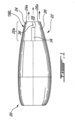
- FIG. 1 there is shown an example of a nacelle 20 including a thrust reverser 22 in the aft section 20a of the nacelle 20.
- the turbofan gas turbine engine is located within the nacelle 20 and the nacelle 20 is attached under the wings or on the fuselage of the aircraft using an appropriate arrangement (not shown).
- the thrust reverser 22 comprises two opposite pivoting doors 24, 26 forming most of the exhaust nozzle of the nacelle 20 when they are in their stowed position. In the example illustrated in FIG. 2 , one door 24 is at the upper side and the other door 26 is at the bottom side.
- the nacelle 20 defines an outer aerodynamic shape, referred to herein as the outer mold line (OML) of the assembly.
- OML outer mold line
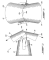
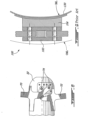
- FIG. 2 is an enlarged view showing an example of a jet pipe 30 having rearwardly extending jet pipe arms 32 to which the doors 24, 26 are pivotally connected. The doors 24, 26 are in their deployed position in FIG. 2.
- FIG. 3 is a rear view of what is shown in FIG. 2 .
- the jet pipe 30 is concealed inside the aft section 20a of the nacelle 20 when the doors 24, 26 are in their stowed position, as in FIG. 1 .
- the interior of the jet pipe together with the interior of the doors when stowed, defines an inner aerodynamic shape or nozzle for direct exhaust gases of the engine, and this inner shape is referred to herein as the inner mold line (IML) of the assembly (see FIG. 5 ).
- IML inner mold line
- FIG. 2 The arrows in FIG. 2 indicate the main flow path when the engine is operated during a thrust reversal.
- exhaust gases from the engine are redirected substantially forwardly when the doors 24, 26 are in their deployed position.
- the gases exit the doors 24, 26 in the vicinity of their leading edges 24b, 26b.
- These edges 24b, 26b are located at the front of the doors 24, 26 and are referred to as "leading" edges with reference to the travel path of the aircraft.
- the redirection of the exhaust gases from the engine creates a resulting horizontal retarding force opposing the forward movement of the aircraft.
- Increasing the output thrust generated by the engine increases the aerodynamic decelerating force.
- the trailing edge 24a of the upper door 24 is pivoted behind the trailing edge 26a of the lower door 26, this resulting from the asymmetrical positioning of the pivots with reference to the horizontal medial plane of the jet pipe 30, as described in EP1903205 .
- actuators the pivots and the mechanisms provided to lock the front of the doors 24, 26 during the direct thrust operation of the engine have been omitted from FIGS. 2 and 3 , for clarity.
- an actuator system is to be provided on each side of the jet pipe 30, for instance, generally underneath a fairing 34 between the longitudinal sides of the doors 24, 26 when the doors are in their stowed position.
- a fairing 36 is provided for covering the door pivots when the doors are stowed.
- Fairings 34, 36 merge smoothly with nacelle 20 and doors 24, 26, when the doors are stowed, to provide an aerodynamically smooth outer mold line (OML) to the assembly.
- OML outer mold line
- the actuators, pivots and pivot arms of the doors must reside within the envelope defined by the outer mold line (OML) and inner mold line (IML).
- FIG. 4 shows an example of an individual pivot fitting 50.
- the pivot fitting 50 comprises a base 52 having a slightly arcuate shape.
- the curvature of the base 52 corresponds to the curvature of the jet pipe arm 32 in which the pivot fitting 50 will be positioned, and thus each pivot is designed to substantially follow the curvature of the space between the OML and IML and thus minimize the envelope needed therebetween.
- the illustrated base 52 is substantially rectangular. Other shapes can be used as well.
- the pivot fitting 50 also includes a shaft 54 projecting from one of the main sides of the base 52, namely the side that will be toward the outside of the reverser assembly.
- the shaft 54 is disposed on the base so that it projects normally to the plane of door rotation, i.e.
- the shafts 54 preferably include a coaxially disposed threaded bore 56 defined in the free end of the shaft. This threaded bore 56 can be used to receive a bolt, as explained hereafter.
- the base 52 also includes holes 58 for receiving fasteners.
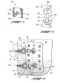
- FIG. 5 shows an example of the interior of a jet pipe arm 32 in which two pivot fittings 50 are provided.
- Each pivot fitting 50 is inserted into a recess 60 that is configured and disposed so that the pivot fittings 50 will be flush mounted with reference to the inner surface of the jet pipe arm 32, so that the aerodynamics of inner mold line (IML) of the jet pipe is not affected.
- the recess 60 is, for instance, a cut-away portion or a punched portion of the jet pipe arm 32.
- the jet pipe arm 32 also includes a side opening corresponding to each pivot fitting 50 for receiving its shaft 54. Each shaft 54 outwardly projects with reference to the jet pipe arm 32, as shown for instance in FIG. 6.
- FIG. 6 shows an example of the interior of a jet pipe arm 32 in which two pivot fittings 50 are provided.
- Each pivot fitting 50 is inserted into a recess 60 that is configured and disposed so that the pivot fittings 50 will be flush mounted with reference to the inner surface of the jet pipe arm 32, so that the aerodynamic
- FIG. 6 also shows that the illustrated pivot fittings 50 are connected to the jet pipe arm 32 using a plurality of bolts 62. Other fastening arrangements are also possible. While it is possible to provide two shafts 54 on a same side of a single base, the illustrated example uses two distinct pivot fittings 50, namely an upper door pivot fitting and a lower door pivot fitting, each having their own shaft 54. This facilitates maintenance since it is possible to only remove one door at a time. Each pivot fitting 50 is removable from inside the jet pipe 30.
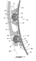
- FIG. 7 is a cross sectional view taken along line 7-7 in FIG. 6 . It shows the pivot fitting 50 being flush mounted inside the jet pipe arm 32. Bolts 62 are used in the illustrated embodiment for connecting the pivot fitting 50 to the jet pipe arm 32. The bolts heads can be hidden in chamfered holes. Also, FIG. 7 shows that the recess of the jet pipe arm 32 may require a reinforcement layer or embossed portion on the opposite side. This layer or portion is also shown in FIG. 6 .
- FIG. 8 shows the arrangement of FIG. 6 when assembled.
- FIG. 8 shows the pivot arm 70 for the upper door 24 and the pivot arm 72 for the lower door 26.
- the pivots for these pivot arms 70, 72 are asymmetrically disposed with reference to a medial plane of the jet pipe arm 32, as described in EP1903205 .
- the pivot arms 70, 72 are preferably overlapping or crossing one another when the doors 24, 26 are in their stowed position, which thus allows a planar exit of the thrust reverser nozzle when the doors are stowed. Other arrangements are possible as well.
- FIG. 8 shows the pivot arm 70 for the upper door 24 and the pivot arm 72 for the lower door 26.
- the pivots for these pivot arms 70, 72 are asymmetrically disposed with reference to a medial plane of the jet pipe arm 32, as described in EP1903205 .
- the pivot arms 70, 72 are preferably overlapping or crossing one another when the doors 24, 26 are in their stowed position, which thus allows a planar exit of the
- pivot arms 70, 72 has a pivot receiving hole for coaxially mounting the door on the shaft 54 of the corresponding pivot fitting 50 (the other end of each pivot arm is mounted to, or integrated with, its associated door 24, 26).
- a bearing 80 (see FIG. 7 ), preferably a spherical type, separates the pivot arm 70, 72 from the shaft 54. The bearings 80 lower the friction to a minimum and compensates any slight misalignment of the pivoting axis of the doors.
- the pivot arms 70, 72 may be connected to the corresponding shafts 54 and retained via a bolt 74 provided in the threaded bore 56 of the shaft 54, as best shown in FIG. 7 .
- Each bolt 74 is used with a set of washers 76, 78, one of which 76 is a bendable lock washer cooperating with a notch in the shaft 54 for preventing the bolt 74 from rotating once it is installed.
- the other washer 78 provides adjustment of the reverser door in the transverse direction for easier adjustment of the reverser door position. Other arrangements can also be used as well.
- the bolts 74 can be prevented from rotating using any other accepted methods in aeronautics.
- the shaft 54 is sized for adequately taking the loading conditions in direct and reverse thrust, and has an adequate diameter for supporting the bearing 80 installed on each shaft 54. Referring to FIG.
- each pivot arm 70, 72 has a curvature about the engine selected to follow the curvature of the space available between the OML and IML, and the hinges are configured to cross each other when the reverser doors move towards their stowed position.
- Lower pivot arm 72 is curved generally to follow the local outer profile of the jet pipe 30.
- Upper pivot arm 70 is curved to follow the local outer profile of the jet pipe 30, but also to avoid interference. with lower pivot arm 72 (since the pivots cross one another). This curvature assists in reducing the profile of the door-hinge arrangement, and allows a further reduction in the OML of the assembly.
- any suitable radius (or radii) of curvature may be provided, and that the "curvature" need not be continuous, nor arcuate, as depicted.
- FIG. 9 schematically shows a prior art thrust reverser hinge arrangement.
- Each pivot fitting 100 has a clevis 102 that has an integral base 104 riveted to the jet pipe 130.
- the jet pipe 130 defines an inner mold line (IML) and the nacelle or thrust reverser outer skin defines an outer mold line (OML) for the assembly.
- IML inner mold line
- OML outer mold line
- the envelope required to fit the prior art configuration is significantly larger than that required to fit the arrangement described above.
- the prior art has a significantly larger OML and nacelle wetted area, factors that contribute to the increase of the nacelle drag when the reverser nozzle is in its stowed position, in order to accommodate the larger apparatus of the prior art.
- a thrust reverser door 24, 26 onto jet pipe 30, e.g. during assembly or after maintenance, one positions the thrust reverser doors, then inserts a pivot fitting 50 inside the jet pipe 30 through its cutout and slides its shaft 54 (that is outwardly projecting through a side opening of the jet pipe 30) through the end of the pivot arm 70, 72 and bearing 80 of the door 24, 26, and then mounts a nut or other fastener to the shaft for securing the reverser door arms on their respective shaft.
- pivot fittings 50 and pivot arms 70, 72 provide both a low profile and light structure to which the thrust reverser doors 24, 26 can be attached, and thereby assist in reducing the overall nacelle wetted area, as well as assembly weight.
- the shapes of the doors and the configuration of these doors with reference to each other may be different to what is shown and described.
- the shape and configuration of the base can be different to the rectangular one shown in the figures.
- the illustrated shaft can be replaced by a similar shaft-like member, for instance a large bolt or peg that is partially inserted in a corresponding threaded hole at the center of the base.
- the shaft-like member can also be made removable if, for instance, it is connected to the base by the threaded bolt holding the door or by a threaded end.
- doors 24, 26 are described herein and shown in the figures as being an upper reverser door 24 and a lower reverser door 26 movable in a vertical plane, doors may be configured with another suitable orientation, such as a left door and right door movable in a horizontal plane. Other suitable arrangements are possible as well.
Landscapes
- Engineering & Computer Science (AREA)
- Chemical & Material Sciences (AREA)
- Combustion & Propulsion (AREA)
- Mechanical Engineering (AREA)
- General Engineering & Computer Science (AREA)
- Pivots And Pivotal Connections (AREA)
- Sliding-Contact Bearings (AREA)
- Structures Of Non-Positive Displacement Pumps (AREA)
Claims (11)
- Schubumkehrer (22), umfassend:eine erste und eine zweite Schubumkehrklappe (24, 26), die ein Strahlrohr (30) umgeben, um eine Auslassdüse (28) mit einer aerodynamischen äußeren und inneren Formlinienfläche (OML, IML) zu bilden,wobei jede Klappe (24, 26) ein Paar gegenüberliegender Schwenkarme (70, 72) aufweist;wobei das Strahlrohr (30) ein Paar Strahlrohrarme (32) mit Innenflächen aufweist, die entsprechende Abschnitte der inneren Formlinienfläche (IML) definieren;wobei jede Klappe (24, 26) an den Schwenkarmen (70, 72) an den Strahlrohrarmen (32) durch eine Klappenschwenkanordnung schwenkbar montiert ist, die einen Schwenkbeschlag (50) umfasst, der aufweist: eine Basis (52), wobei die Strahlrohrarme (32) jeweils eine Aussparung (60) aufweisen, die die Basis (52) im Wesentlichen bündig mit der inneren Formlinienfläche (IML) zusammenwirkend aufnimmt, und einen Schaft (54), der sich von der Basis (52) durch eine Öffnung des Strahlrohrarms (32) nach außen erstreckt und schwenkbar mit entsprechenden der Schwenkarme (70, 72) verbunden ist, wobei die Öffnung so bemessen ist, dass der Schaft (54) durch die Öffnung hindurchtreten kann, jedoch verhindert wird, dass die Basis (52) durch die Öffnung hindurchtritt.
- Schubumkehrer nach Anspruch 1, wobei:die erste und die zweite Klappe (24, 26) eine Ausgangsdüse (28) mit einem Krümmungsradius bilden; undjede Klappe (24, 26) einen sich in Umfangsrichtung erstreckenden Schubumlenkabschnitt umfasst und das Paar Schwenkarme (70, 72) auf beiden Seiten des Umlenkabschnitts angeordnet ist, wobei jeder Schwenkbeschlag Befestigungseinrichtungen (62) aufweist, die sich durch diesen hindurch erstrecken, zum Befestigen des Beschlags an dem Strahlrohrarm, wobei sich die Schwenkarme (70, 72) von dem Schubumlenkabschnitt zu einem freien Ende erstrecken, wobei die Schwenkarme (70, 72) einen entsprechenden Krümmungsradius aufweisen, der der Ausgangsdüsenkrümmung folgt, wobei benachbarte Schwenkarme (70, 72) umeinander gekrümmt sind.
- Schubumkehrer nach Anspruch 1, wobei die Schwenkbeschlagbasen (52) fest an den Strahlrohrarmen (32) bündig mit der inneren Formlinienfläche (IML) montiert sind.
- Schubumkehrer nach Anspruch 3, wobei die Schwenkarme (70, 72) in ihrer Krümmung mit der Auslassdüse radial zwischen der äußeren und der inneren Formlinienfläche (OML, IML) übereinstimmen.
- Schubumkehrer nach Anspruch 4, wobei jeder der Schwenkbeschläge (50) ferner ein Lager (80) umfasst, das auf dem Schaft (54) im Inneren einer entsprechenden Öffnung in den Schwenkarmen (70, 72) montiert ist, wobei eine äußere und eine innere Unterlegscheibe (76, 78) das Lager (80) auf dem Schaft (54) halten und ein Bolzen (74) mit dem Schaft (54) in Eingriff steht, um wiederum die äußere Unterlegscheibe (76), das Lager (80) und die innere Unterlegscheibe (78) auf dem Schaft (54) zu sichern.
- Schubumkehrer nach Anspruch 4, wobei benachbarte Schwenkarme (70, 72) der Klappen (24, 26) einander kreuzen und sich radial zwischen der äußeren und der inneren Formlinienfläche (OML, IML) überlappen, wenn die Klappen in ihrer verstauten Position sind.
- Schubumkehrer nach Anspruch 1, wobei der Schaft (54) eine Befestigungsanordnung (74, 76) zum Sichern eines Endes des Schwenkarms der Schubumkehrklappe umfasst.
- Schubumkehrer nach Anspruch 1 oder 7, ferner umfassend mehrere mit Gewinde versehene Befestigungseinrichtungen (62), die die Basis (52) abnehmbar an den Strahlrohrarmen (32) befestigen.
- Schubumkehrer nach Anspruch 1, wobei die zweite Seite der Basis (52) einen Krümmungsradius aufweist, der im Wesentlichen dem Krümmungsradius der Strahlrohrarme (32) in dem Bereich entspricht, in dem die Basis montiert ist.
- Schubumkehrer nach einem vorhergehenden Anspruch, ferner umfassend eine Unterlegscheibe (78), die eine Innenseite des Schwenkarms von der ersten Seite der Basis trennt, wobei die Unterlegscheibe eine Breite aufweist, die so gewählt ist, dass sie bei Einstellung der Klappe einen gewünschten Abstand vorsieht.
- Verfahren zum schwenkbaren Verbinden einer Schubumkehrklappe mit einem Schubumkehrer nach Anspruch 1, wobei das Verfahren die Schritte umfasst zum:Vorsehen einer Öffnung in einem der Strahlrohrarme;Vorsehen der ersten Klappe mit dem Paar gegenüberliegender Schwenkarme, wobei jeder Schwenkarm ein Schwenkaufnahmeloch aufweist;Einsetzen eines ersten Schwenkbeschlags durch die Öffnung von einer Innenseite des Strahlrohrs, so dass der Schaft einen Schwenkpunkt des ersten Schwenkbeschlags definiert, der sich zu einer Außenseite des Strahlrohrs und durch das Schwenkaufnahmeloch eines Schwenkarms erstreckt; undAnbringen des ersten Schwenkbeschlags an dem einen Strahlrohrarm.
Applications Claiming Priority (1)
| Application Number | Priority Date | Filing Date | Title |
|---|---|---|---|
| US11/941,371 US8172175B2 (en) | 2007-11-16 | 2007-11-16 | Pivoting door thrust reverser for a turbofan gas turbine engine |
Publications (3)
| Publication Number | Publication Date |
|---|---|
| EP2060767A2 EP2060767A2 (de) | 2009-05-20 |
| EP2060767A3 EP2060767A3 (de) | 2013-02-13 |
| EP2060767B1 true EP2060767B1 (de) | 2025-05-21 |
Family
ID=40364152
Family Applications (1)
| Application Number | Title | Priority Date | Filing Date |
|---|---|---|---|
| EP08252854.8A Active EP2060767B1 (de) | 2007-11-16 | 2008-08-28 | Schubumkehrdüse mit schwenkbarer Klappe eines Gasturbinenturbofantriebwerks |
Country Status (3)
| Country | Link |
|---|---|
| US (1) | US8172175B2 (de) |
| EP (1) | EP2060767B1 (de) |
| CA (1) | CA2638842C (de) |
Families Citing this family (24)
| Publication number | Priority date | Publication date | Assignee | Title |
|---|---|---|---|---|
| US8434715B2 (en) * | 2009-07-30 | 2013-05-07 | Jean-Pierre Lair | Nested fairing thrust reverser |
| US9097209B2 (en) | 2012-03-27 | 2015-08-04 | United Technologies Corporation | Gas turbine engine thrust reverser system |
| WO2014074143A1 (en) | 2012-11-12 | 2014-05-15 | United Technologies Corporation | Aircraft with forward sweeping t-tail |
| US9211955B1 (en) * | 2012-12-10 | 2015-12-15 | The Boeing Company | Methods and apparatus for supporting engines and nacelles relative to aircraft wings |
| US9617009B2 (en) | 2013-02-22 | 2017-04-11 | United Technologies Corporation | ATR full ring sliding nacelle |
| US9631578B2 (en) | 2013-02-22 | 2017-04-25 | United Technologies Corporation | Pivot thrust reverser surrounding inner surface of bypass duct |
| US9726112B2 (en) | 2013-03-07 | 2017-08-08 | United Technologies Corporation | Reverse flow gas turbine engine airflow bypass |
| US9574520B2 (en) | 2013-03-07 | 2017-02-21 | United Technologies Corporation | Reverse core engine thrust reverser for under wing |
| US9897040B2 (en) | 2013-03-07 | 2018-02-20 | United Technologies Corporation | Rear mounted reverse core engine thrust reverser |
| US9845159B2 (en) | 2013-03-07 | 2017-12-19 | United Technologies Corporation | Conjoined reverse core flow engine arrangement |
| US9394802B2 (en) * | 2013-03-10 | 2016-07-19 | United Technologies Corporation | Sensor hoop storage and transport apparatus |
| EP2971728B1 (de) | 2013-03-14 | 2020-09-02 | United Technologies Corporation | Doppelziel-schubumkehrermodul |
| US9784214B2 (en) | 2014-11-06 | 2017-10-10 | Rohr, Inc. | Thrust reverser with hidden linkage blocker doors |
| US10655564B2 (en) | 2016-05-13 | 2020-05-19 | Rohr, Inc. | Thrust reverser system with hidden blocker doors |
| US9976696B2 (en) | 2016-06-21 | 2018-05-22 | Rohr, Inc. | Linear actuator with multi-degree of freedom mounting structure |
| US11396854B2 (en) * | 2017-10-25 | 2022-07-26 | Rohr, Inc. | Hinge mechanism for pivot door thrust reversers |
| US10704495B2 (en) | 2017-11-27 | 2020-07-07 | Rohr, Inc. | Pre-exit pivot door thrust reverser |
| US10724474B2 (en) | 2018-05-01 | 2020-07-28 | Rohr, Inc. | Hybrid articulating/translating trailing edge reverser |
| US11333102B2 (en) | 2018-09-06 | 2022-05-17 | Rohr, Inc. | Thrust reverser actuation arrangement and deployable fairing systems and methods |
| US11346304B2 (en) | 2018-09-06 | 2022-05-31 | Rohr, Inc. | Thrust reverser single degree of freedom actuator mechanism systems and methods |
| US11300077B2 (en) | 2018-10-02 | 2022-04-12 | Rohr, Inc. | Deployable fairing for door reversers systems and methods |
| US10906661B2 (en) * | 2018-11-05 | 2021-02-02 | Rohr, Inc. | Nacelle cowl hinge |
| US11591985B2 (en) * | 2020-10-21 | 2023-02-28 | Pratt & Whitney Canada Corp. | Method and system for thrust reverser operation |
| US20250327430A1 (en) * | 2024-04-19 | 2025-10-23 | Mra Systems Llc | Aircraft propulsion system and thrust reverser mechanism |
Family Cites Families (210)
| Publication number | Priority date | Publication date | Assignee | Title |
|---|---|---|---|---|
| GB745649A (en) | 1953-01-15 | 1956-02-29 | Rolls Royce | Improvements in or relating to aircraft reaction-propulsion units and installations |
| GB788359A (en) | 1954-11-26 | 1958-01-02 | Power Jets Res & Dev Ltd | Discharge nozzles for propulsive jets |
| US2847823A (en) * | 1955-03-15 | 1958-08-19 | Curtiss Wright Corp | Reverse thrust nozzle construction |
| US3347578A (en) * | 1964-11-18 | 1967-10-17 | Boeing Co | Flush-type safety latch |
| GB1130268A (en) * | 1967-07-01 | 1968-10-16 | Rolls Royce | Improvements in or relating to gas turbine by-pass engines |
| US3550855A (en) * | 1968-08-23 | 1970-12-29 | Boeing Co | Target-type thrust reverser |
| US3541794A (en) * | 1969-04-23 | 1970-11-24 | Gen Electric | Bifurcated fan duct thrust reverser |
| GB1293232A (en) * | 1969-07-28 | 1972-10-18 | Aerospatiale | Fluid discharge nozzles having means for deflecting the flow of fluid discharged |
| US3610534A (en) | 1969-12-18 | 1971-10-05 | Rohr Corp | Thrust-reversing apparatus for jet-propelled aircraft |
| US3640468A (en) | 1970-03-30 | 1972-02-08 | Lockheed Aircraft Corp | Thrust reverser for asymmetric exhaust efflux deflection |
| US3684182A (en) * | 1970-09-08 | 1972-08-15 | Rohr Corp | Variable nozzle for jet engine |
| DE2241817C3 (de) * | 1972-08-25 | 1975-04-03 | Motoren- Und Turbinen-Union Muenchen Gmbh, 8000 Muenchen | Schubumkehrvorrichtung für ein mit einer Nachverbrennungsanlage ausgerüstetes Turbinenstrahltriebwerk eines Flugzeugs |
| GB1506588A (en) | 1975-10-11 | 1978-04-05 | Rolls Royce | Gas turbine engine power plants for aircraft |
| FR2348371A1 (fr) | 1976-04-14 | 1977-11-10 | Astech | Inverseur de poussee pour moteur a reaction |
| FR2382593A1 (fr) * | 1977-03-04 | 1978-09-29 | Hurel Dubois Avions | Dispositif pour la commande d'un inverseur de poussee pour moteur a reaction |
| US4182501A (en) * | 1977-03-04 | 1980-01-08 | Astech | Thrust reverser for jet engine forming active extension of jet tube |
| US4232516A (en) * | 1977-10-05 | 1980-11-11 | Rolls-Royce Limited | Flow deflecting devices |
| US4175385A (en) | 1977-12-12 | 1979-11-27 | General Electric Company | Thrust reverser for an asymmetric aircraft exhaust nozzle |
| US4292803A (en) * | 1979-01-19 | 1981-10-06 | Rohr Industries, Inc. | Turbo fan engine mixer |
| FR2456216A1 (fr) * | 1979-05-11 | 1980-12-05 | Astech Sa | Turbomoteur a double flux equipe d'un inverseur de poussee |
| FR2494775B1 (fr) * | 1980-11-27 | 1985-07-05 | Astech | Dispositif pour la commande d'un inverseur de poussee pour moteur a reaction |
| FR2500537B1 (fr) * | 1981-02-24 | 1985-07-05 | Astech | Dispositif de securite pour inverseur de poussee associe a un moteur a reaction d'aeronef |
| FR2526872B1 (fr) * | 1982-05-17 | 1986-12-26 | Hurel Dubois Avions Const | Inverseur de poussee a porte notamment pour moteur d'avion a reaction |
| US4519561A (en) | 1983-05-23 | 1985-05-28 | Rohr Industries, Inc. | Aircraft thrust reverser mechanism |
| GB2161862B (en) | 1983-05-27 | 1988-05-05 | Pierre Giraud | Double flow turbine engine equipped with a thrust reverser |
| EP0190342A1 (de) | 1984-08-01 | 1986-08-13 | Sundstrand Corporation | Betätigungssystem der schubkraftumkehr für mehrmotoriges flugzeug |
| GB2168298B (en) * | 1984-12-13 | 1988-01-27 | Rolls Royce | Thrust reverser |
| FR2601077B1 (fr) | 1986-07-07 | 1988-10-21 | Hurel Dubois Avions | Structure d'ejection des gaz pour moteur a reaction notamment pour reacteur a double flux. |
| FR2604482B1 (fr) | 1986-09-25 | 1989-12-15 | Fage Etienne | Inverseur de poussee pour moteur a reaction d'aeronef et moteur d'aeronef equipe dudit inverseur de poussee |
| FR2611233B1 (fr) | 1987-02-19 | 1991-05-10 | Hurel Dubois Avions | Groupe moto-propulseur d'avion du type a ventilateur capote equipe d'un inverseur de poussee a portes |
| US4830519A (en) * | 1987-04-06 | 1989-05-16 | United Technologies Corporation | Annular seal assembly |
| FR2618853B1 (fr) | 1987-07-29 | 1989-11-10 | Hispano Suiza Sa | Inverseur de poussee de turboreacteur muni d'un deflecteur mobile de porte |
| US4836451A (en) * | 1987-09-10 | 1989-06-06 | United Technologies Corporation | Yaw and pitch convergent-divergent thrust vectoring nozzle |
| FR2621082A1 (fr) | 1987-09-30 | 1989-03-31 | Hispano Suiza Sa | Inverseur de poussee de turboreacteur a portes munies d'une plaque au profil de veine |
| FR2622929A1 (fr) | 1987-11-05 | 1989-05-12 | Hispano Suiza Sa | Inverseur de poussee de turboreacteur a grilles,a section variable d'ejection |
| FR2622928A1 (fr) | 1987-11-05 | 1989-05-12 | Hispano Suiza Sa | Inverseur de poussee de turboreacteur a portes,a section variable d'ejection |
| FR2627807B1 (fr) | 1988-02-25 | 1990-06-29 | Hispano Suiza Sa | Inverseur de poussee de turboreacteur a double flux equipe de bords de deviation munis de levres mobiles |
| US4922712A (en) | 1988-03-28 | 1990-05-08 | General Electric Company | Thrust reverser for high bypass turbofan engine |
| FR2634251B1 (fr) | 1988-07-18 | 1993-08-13 | Hispano Suiza Sa | Inverseur de poussee de turboreacteur a double flux equipe de bords de deviation mobiles |
| FR2635825B1 (fr) | 1988-08-29 | 1990-11-30 | Hurel Dubois Avions | Inverseur de poussee pour moteur a reaction de type a portes equipees de volets auxiliaires |
| FR2638207B1 (fr) | 1988-10-20 | 1990-11-30 | Hispano Suiza Sa | Inverseur de poussee de turboreacteur, a portes pivotantes equilibrees |
| US5192023A (en) | 1988-10-27 | 1993-03-09 | The Dee Howard Company | Jet engine provided with a thrust reverser |
| US4966327A (en) | 1988-10-27 | 1990-10-30 | The Dee Howard Company | Jet engine provided with a thrust reverser |
| CA1326767C (en) * | 1988-10-27 | 1994-02-08 | Etienne Fage | Jet engine provided with a thrust reverser |
| FR2638784B1 (fr) | 1988-11-09 | 1990-12-21 | Hispano Suiza Sa | Inverseur de poussee de turboreacteur muni de portes a mini-tuyere de deviation du flux inverse |
| FR2638783B1 (fr) * | 1988-11-10 | 1991-04-05 | Astech | Inverseur de poussee notamment pour moteur a reaction d'aeronef |
| US4909346A (en) | 1989-06-27 | 1990-03-20 | Nordam | Jet engine noise suppression system |
| US5039171A (en) | 1989-08-18 | 1991-08-13 | Societe Anonyme Dite Hispano-Suiza | Multi-panel thrust reverser door |
| FR2651278B1 (fr) | 1989-08-23 | 1994-05-06 | Hispano Suiza | Inverseur a grilles sans capot coulissant pour turboreacteur. |
| US5101621A (en) | 1989-09-25 | 1992-04-07 | Rohr Industries, Inc. | Integrated corner for ducted fan engine shrouds |
| US4998409A (en) | 1989-09-25 | 1991-03-12 | Rohr Industries, Inc. | Thrust reverser torque ring |
| US5083426A (en) | 1989-10-02 | 1992-01-28 | Rohr Industries, Inc. | Integrated engine shroud for gas turbine engines |
| US5167118A (en) | 1989-11-06 | 1992-12-01 | Nordam | Jet engine fixed plug noise suppressor |
| GB2393941B (en) * | 1990-01-26 | 2004-09-29 | Rolls Royce Plc | Vectorable variable area nozzle |
| US5120004A (en) | 1990-02-05 | 1992-06-09 | Rohr, Inc. | Split door thrust reverser for fan jet aircraft engines |
| US5117630A (en) | 1990-02-12 | 1992-06-02 | Rohr Industries, Inc. | Pivoting door thrust reverser |
| US5243817A (en) | 1990-07-05 | 1993-09-14 | Rohr, Inc. | Thrust reverser for fan jet aircraft engines |
| FR2669679B1 (fr) | 1990-11-28 | 1994-04-29 | Sud Ouest Conception Aeronauti | Tuyere d'ejection de gaz pour moteur a reaction et moteur a reaction equipe d'une telle tuyere, en particulier moteur du type a flux separes. |
| FR2676779B1 (fr) | 1991-05-21 | 1994-06-03 | Lair Jean Pierre | Tuyere a section variable. |
| US5230213A (en) | 1991-06-12 | 1993-07-27 | Rohr, Inc. | Aircraft turbine engine thrust reverser |
| FR2678026B1 (fr) | 1991-06-24 | 1993-10-15 | Hurel Dubois Avions | Perfectionnement aux inverseurs de poussee de moteur a reaction. |
| US5228641A (en) | 1991-08-15 | 1993-07-20 | Rohr, Inc. | Cascade type aircraft engine thrust reverser with hidden link actuator |
| US5197693A (en) | 1991-08-15 | 1993-03-30 | Rohr, Inc. | Aircraft turbine engine thrust reverser with sliding hinge actuator |
| US5309711A (en) | 1991-08-21 | 1994-05-10 | Rohr, Inc. | Cascade type thrust reverser for fan jet engines |
| FR2680547B1 (fr) | 1991-08-21 | 1993-10-15 | Hispano Suiza | Inverseur de poussee de turboreacteur ayant un bord de deviation a courbure evolutive. |
| FR2681101B1 (fr) | 1991-09-11 | 1993-11-26 | Hispano Suiza | Inverseur de poussee de turboreacteur a pilotage ameliore des nappes du flux inverse. |
| US5203525A (en) | 1991-10-23 | 1993-04-20 | Rohr, Inc. | Hinge with offset pivot line |
| US5209057A (en) | 1991-10-23 | 1993-05-11 | Rohr, Inc. | Rack and pinion actuation for an aircraft engine thrust reverser |
| US5251435A (en) | 1991-10-30 | 1993-10-12 | General Electric Company | Reverser inner cowl with integral bifurcation walls and core cowl |
| FR2683859B1 (fr) | 1991-11-15 | 1994-02-18 | Hispano Suiza | Inverseur de poussee de turboreacteur a double flux. |
| US5419515A (en) | 1991-11-26 | 1995-05-30 | Aeronautical Concept Of Exhaust, Ltd. | Thrust reverser for jet engines |
| US5181676A (en) | 1992-01-06 | 1993-01-26 | Lair Jean Pierre | Thrust reverser integrating a variable exhaust area nozzle |
| US5176340A (en) | 1991-11-26 | 1993-01-05 | Lair Jean Pierre | Thrust reverser with a planar exit opening |
| US5224342A (en) | 1992-02-13 | 1993-07-06 | Lair Jean Pierre | Latching and sealing arrangement for jet engine thrust reverser |
| IT1257222B (it) | 1992-06-09 | 1996-01-10 | Alenia Aeritalia & Selenia | Dispositivo inversore di spinta per motori aeronautici a getto. |
| US5251453A (en) * | 1992-09-18 | 1993-10-12 | General Motors Corporation | Low refrigerant charge detection especially for automotive air conditioning systems |
| US5390879A (en) | 1992-11-23 | 1995-02-21 | Lair; Jean-Pierre | Jet pipe for supporting a thrust reverser for aircraft jet engines |
| FR2698913B1 (fr) | 1992-12-04 | 1995-02-03 | Hurel Dubois Avions | Ensemble d'inversion de poussée à portes équipé d'un dispositif de contrôle de jet. |
| US5372006A (en) | 1993-02-08 | 1994-12-13 | Aeronautical Concept Of Exhaust, Ltd. | Turbine engine equipped with thrust reverser |
| FR2706947B1 (de) | 1993-06-23 | 1995-07-28 | Hispano Suiza Sa | |
| EP0635632B1 (de) | 1993-06-25 | 1997-10-22 | THE NORDAM GROUP, Inc. | System zur Schalldämpfung |
| FR2711733B1 (fr) | 1993-10-22 | 1996-01-26 | Hurel Dubois Avions | Inverseur de poussée à portes pour moteur d'avion à réaction équipées d'un volet auxiliaire. |
| US5720449A (en) | 1993-11-19 | 1998-02-24 | Societe De Construction Des Avions Hurel-Dubois | Thrust reverser with doors for aircraft engine, equipped with safety systems preventing the untimely opening of the doors |
| FR2712929B1 (fr) | 1993-11-24 | 1995-12-29 | Hispano Suiza Sa | Inverseur de poussée de turboréacteur à double flux. |
| FR2713732B1 (fr) | 1993-12-15 | 1996-01-12 | Hispano Suiza Sa | Transmission à engrenages orbitaux et charge répartie. |
| FR2717860B1 (fr) * | 1994-03-28 | 1996-05-31 | Sud Ouest Conception Aeronauti | Inverseur de poussée doté d'au moins une porte basculante, pour moteur à réaction, notamment d'aéronef, et moteur à réaction équipé de cet inverseur de poussée. |
| FR2721977B1 (fr) | 1994-06-30 | 1996-08-02 | Hispano Suiza Sa | Inverseur de poussee de turboreacteur a double flux a obstacles lies au capot primaire |
| FR2722534B1 (fr) | 1994-07-13 | 1996-08-14 | Hispano Suiza Sa | Inverseur de poussee de turboreacteur double flux, a obstacles externes |
| US5778659A (en) | 1994-10-20 | 1998-07-14 | United Technologies Corporation | Variable area fan exhaust nozzle having mechanically separate sleeve and thrust reverser actuation systems |
| FR2727468B1 (fr) | 1994-11-30 | 1996-12-27 | Hispano Suiza Sa | Inverseur de poussee de turboreacteur a obstacles aval |
| DE69512616T2 (de) * | 1994-12-15 | 2000-06-29 | The Dee Howard Co., San Antonio | Schubumkehrvorrichtung mit in Längsrichtung verschiebbaren Klappen |
| FR2728626B1 (fr) | 1994-12-21 | 1998-03-06 | Hurel Dubois Avions | Inverseur de poussee pour moteur a reaction a bord de deviation amenage |
| US5615834A (en) * | 1995-01-31 | 1997-04-01 | Osman; Medhat A. | Ultra thrust reverser system |
| FR2730763B1 (fr) | 1995-02-21 | 1997-03-14 | Hispano Suiza Sa | Inverseur de poussee a volets aval pour turboreacteur |
| FR2730764B1 (fr) | 1995-02-21 | 1997-03-14 | Hispano Suiza Sa | Inverseur de poussee a portes associees a un panneau aval |
| US5655360A (en) | 1995-05-31 | 1997-08-12 | General Electric Company | Thrust reverser with variable nozzle |
| FR2734868B1 (fr) | 1995-06-02 | 1997-08-14 | Hurel Dubois Avions | Ensemble d'inverseur de poussee a deux portes |
| FR2736390B1 (fr) | 1995-07-05 | 1997-08-08 | Hispano Suiza Sa | Inverseur de poussee de turboreacteur a une coquille |
| US6357672B1 (en) * | 1995-07-06 | 2002-03-19 | United Technologies Corporation | Sealing means for a multi-axis nozzle |
| FR2736682B1 (fr) | 1995-07-12 | 1997-08-14 | Hispano Suiza Sa | Inverseur de poussee de turbomachine a double flux a portes dissymetriques |
| FR2738291B1 (fr) | 1995-09-06 | 1997-09-26 | Hispano Suiza Sa | Inverseur de poussee de turboreacteur a portes associees a un panneau amont formant ecope |
| DE69514224T2 (de) | 1995-09-13 | 2000-08-10 | Societe De Construction Des Avions Hurel-Dubois (S.A.), Meudon-La-Foret | Elektrohydraulische Schubumkehrvorrichtung mit zwei Klappen |
| EP0763653B1 (de) | 1995-09-13 | 2001-07-18 | SOCIETE DE CONSTRUCTION DES AVIONS HUREL-DUBOIS (société anonyme) | Strahlumkehrgitter für eine Schubumkehrvorrichtungsklappe |
| FR2738597B1 (fr) | 1995-09-13 | 1997-10-03 | Hispano Suiza Sa | Inverseur de poussee de turboreacteur a portes associees a un panneau primaire |
| US5730392A (en) | 1995-09-22 | 1998-03-24 | Aeronautical Concept Of Exhaust, Ltd. | Adjustable fairing for thrust reversers |
| FR2740834B1 (fr) | 1995-11-02 | 1997-12-05 | Hispano Suiza Sa | Inverseur de poussee de turboreacteur a double flux muni de portes secondaires |
| FR2741114B1 (fr) | 1995-11-15 | 1997-12-05 | Hispano Suiza Sa | Inverseur de poussee de turboreacteur a obstacles aval tendant a l'equilibrage |
| FR2741910B1 (fr) | 1995-11-30 | 1998-01-02 | Hispano Suiza Sa | Inverseur de poussee de turboreacteur a portes a panneau arriere articule |
| FR2742482B1 (fr) | 1995-12-19 | 1998-02-06 | Hurel Dubois Avions | Inverseur de poussee a tuyere a section reglable pour moteur d'avion a reaction |
| US5826823A (en) | 1996-02-07 | 1998-10-27 | Rohr, Inc. | Actuator and safety lock system for pivoting door thrust reverser for aircraft jet engine |
| EP0789140B1 (de) | 1996-02-08 | 2001-11-07 | Societe De Construction Des Avions Hurel-Dubois | Dichtungsanordnung für schwenkbare Schubumkehrklappe |
| FR2745036B1 (fr) | 1996-02-15 | 1998-04-03 | Hispano Suiza Sa | Inverseur de poussee de turboreacteur a portes associees a un panneau amont |
| FR2745035B1 (fr) | 1996-02-15 | 1998-04-03 | Hispano Suiza Sa | Inverseur de poussee de turboreacteur a portes associees a un panneau amont |
| FR2748525B1 (fr) | 1996-05-09 | 1998-06-19 | Hispano Suiza Sa | Inverseur de poussee de turboreacteur a portes munies d'aubes deflectrices |
| FR2748778B1 (fr) | 1996-05-15 | 1998-06-19 | Hispano Suiza Sa | Inverseur de poussee de turboreacteur a portes associees a un panneau amont |
| FR2748779B1 (fr) | 1996-05-15 | 1998-06-19 | Hispano Suiza Sa | Inverseur de poussee de turboreacteur a portes associees a un panneau amont |
| FR2749041B1 (fr) | 1996-05-23 | 1998-06-26 | Hispano Suiza Sa | Inverseur de poussee de turboreacteur a double flux a obstacles lies au capot primaire |
| US5794433A (en) * | 1996-06-18 | 1998-08-18 | The Nordam Group, Inc. | Thrust reverser door side fillers |
| FR2751377B1 (fr) | 1996-07-18 | 1998-09-04 | Hispano Suiza Sa | Inverseur de poussee de turboreacteur a portes comportant un panneau coulissant |
| FR2752017B1 (fr) | 1996-08-01 | 1998-10-16 | Hispano Suiza Sa | Inverseur de poussee de turboreacteur a portes formant ecopes |
| US6039287A (en) * | 1996-08-02 | 2000-03-21 | Alliedsignal Inc. | Detachable integral aircraft tailcone and power assembly |
| US5806302A (en) | 1996-09-24 | 1998-09-15 | Rohr, Inc. | Variable fan exhaust area nozzle for aircraft gas turbine engine with thrust reverser |
| FR2754314B1 (fr) | 1996-10-03 | 1999-01-08 | Hispano Suiza Sa | Procede et dispositifs de fermeture des portes d'inverseurs de poussee |
| FR2754313B1 (fr) | 1996-10-03 | 1999-01-08 | Hispano Suiza Sa | Inverseur de poussee a portes a installation de verin de commande optimisee |
| FR2754565B1 (fr) | 1996-10-10 | 1999-01-08 | Hispano Suiza Sa | Inverseur de poussee a portes a debit de fuite controle |
| FR2755729B1 (fr) | 1996-11-12 | 1999-01-08 | Fage Etienne | Turbomoteur a double flux pourvu d'une tuyere confluente et d'un inverseur de poussee |
| FR2755730B1 (fr) | 1996-11-14 | 1999-01-08 | Hispano Suiza Sa | Systeme de commande electrique pour inverseur de poussee de turboreacteur |
| FR2756323B1 (fr) | 1996-11-28 | 1998-12-31 | Hispano Suiza Sa | Dispositif de liaison d'un inverseur de poussee a un turbomoteur |
| FR2756868B1 (fr) | 1996-12-05 | 1999-01-08 | Hispano Suiza Sa | Inverseur de poussee de turboreacteur a portes maintenues dans les lignes de nacelle |
| FR2757215B1 (fr) | 1996-12-12 | 1999-01-22 | Hispano Suiza Sa | Inverseur de poussee de turboreacteur a portes comportant des aubes deflectrices associees a la structure fixe |
| EP0852290A1 (de) | 1996-12-19 | 1998-07-08 | SOCIETE DE CONSTRUCTION DES AVIONS HUREL-DUBOIS (société anonyme) | Schubumkehrvorrichtung für ein Bläsertriebwerk |
| FR2757901B1 (fr) | 1996-12-26 | 1999-01-29 | Hispano Suiza Sa | Inverseur de poussee de turboreacteur a double flux a coquilles aval |
| FR2757913B1 (fr) | 1996-12-26 | 1999-01-29 | Hispano Suiza Sa | Dispositif de pivot entre un element mobile et une structure fixe accessible d'un seul cote |
| FR2758161B1 (fr) | 1997-01-09 | 1999-02-05 | Hispano Suiza Sa | Inverseur de poussee a grilles a installation de verin de commande optimisee |
| FR2760047B1 (fr) | 1997-02-27 | 1999-05-07 | Hispano Suiza Sa | Inverseur de poussee de turboreacteur a portes associees a un dispositif de synchronisation de commande |
| US6276026B1 (en) * | 1997-03-10 | 2001-08-21 | The Boeing Company | Aircraft hinge |
| FR2760789B1 (fr) | 1997-03-13 | 2001-09-07 | Hispano Suiza Sa | Inverseur de poussee de turboreacteur a portes a structure externe autoraidie |
| FR2760788B1 (fr) | 1997-03-13 | 1999-05-07 | Hispano Suiza Sa | Inverseur de poussee de turboreacteur a portes a structure externe plaquee |
| FR2761733B1 (fr) | 1997-04-03 | 1999-06-11 | Hispano Suiza Sa | Inverseur de poussee pour turbomoteur d'aeronef |
| FR2761734B1 (fr) | 1997-04-03 | 1999-06-11 | Hispano Suiza Sa | Dispositif de fermeture et de verrouillage des obturateurs d'un inverseur de poussee |
| FR2762875B1 (fr) | 1997-04-30 | 1999-06-04 | Hispano Suiza Sa | Inverseur de poussee protege en cas de deverrouillage accidentel |
| FR2764341B1 (fr) | 1997-06-05 | 1999-07-16 | Hispano Suiza Sa | Inverseur de poussee de turboreacteur a portes formant ecopes associees a un deflecteur mobile |
| US5875995A (en) | 1997-05-20 | 1999-03-02 | Rohr, Inc. | Pivoting door type thrust reverser with deployable members for efflux control and flow separation |
| FR2764000B1 (fr) | 1997-06-03 | 1999-08-13 | Hurel Dubois Avions | Structure d'ejection equipee d'un inverseur de poussee a deux portes arriere et a section de sortie plane |
| FR2764339B1 (fr) | 1997-06-05 | 1999-07-16 | Hispano Suiza Sa | Inverseur de poussee de turboreacteur a portes formant ecopes associees a une casquette amont mobile |
| FR2764340B1 (fr) | 1997-06-05 | 1999-07-16 | Hispano Suiza Sa | Inverseur de poussee de turboreacteur a portes munies d'un becquet mobile a entrainement optimise |
| FR2764643B1 (fr) | 1997-06-12 | 1999-07-16 | Hispano Suiza Sa | Inverseur de poussee a portes de turboreacteur a section variable d'ejection |
| FR2764644B1 (fr) | 1997-06-12 | 1999-07-16 | Hispano Suiza Sa | Turboreacteur a double flux associe a un inverseur de poussee avec un carenage rapporte dans la veine fluide |
| FR2765917B1 (fr) | 1997-07-10 | 1999-08-20 | Hispano Suiza Sa | Inverseur de poussee a visualisation de verrouillage |
| FR2765916B1 (fr) | 1997-07-10 | 1999-08-20 | Hispano Suiza Sa | Inverseur de poussee a resistance amelioree aux impacts |
| FR2766522B1 (fr) | 1997-07-24 | 1999-09-03 | Hispano Suiza Sa | Inverseur de poussee de turbosoufflante a obstacle a guidage axial lies au capot primaire |
| US6173807B1 (en) * | 1998-04-13 | 2001-01-16 | The Boeing Company | Engine nacelle acoustic panel with integral wedge fairings and an integral forward ring |
| US5927647A (en) | 1997-09-24 | 1999-07-27 | Rohr, Inc. | Blocker door frame pressure structure for translating cowl of cascade thrust reverser for aircraft jet engine |
| FR2768773B1 (fr) | 1997-09-25 | 1999-11-05 | Hispano Suiza Sa | Inverseur de poussee de turboreacteur a coquilles internes |
| FR2771171B1 (fr) | 1997-11-20 | 1999-12-31 | Hispano Suiza Sa | Dispositif de mesure de la pousse axiale sur un arbre tournant |
| FR2774431B1 (fr) | 1998-02-04 | 2000-03-03 | Hispano Suiza Sa | Inverseur de poussee de turboreacteur a obstacles aval |
| FR2776023B1 (fr) | 1998-03-12 | 2000-04-07 | Hispano Suiza Sa | Inverseur de poussee de turboreacteur a portes formant ecopes associees a une grille mobile |
| FR2777043B1 (fr) | 1998-04-02 | 2000-05-12 | Hispano Suiza Sa | Inverseur de poussee de turboreacteur a portes formant ecopes associees a un capotage externe articule |
| FR2780101B1 (fr) | 1998-06-18 | 2000-07-28 | Hispano Suiza Sa | Inverseur de poussee de turboreacteur a portes formant ecopes a section d'echappement adaptable |
| US6027071A (en) * | 1998-08-31 | 2000-02-22 | Lair; Jean-Pierre | Thrust reverser with throat trimming capability |
| FR2783018B1 (fr) | 1998-09-03 | 2000-10-13 | Hispano Suiza Sa | Nacelle de turboreacteur a double flux a element mobile mis a la masse |
| US6170254B1 (en) | 1998-12-18 | 2001-01-09 | Rohr, Inc. | Translating sleeve for cascade type thrust reversing system for fan gas turbine engine for an aircraft |
| US6260801B1 (en) * | 1999-09-17 | 2001-07-17 | The Nordam Group, Inc. | Swing pivot thrust reverser |
| FR2799796B1 (fr) | 1999-10-14 | 2002-08-30 | Hispano Suiza Sa | Inverseur de poussee de turboreacteur a portes a pivots centres |
| US6293495B1 (en) | 1999-12-08 | 2001-09-25 | Rohr, Inc. | Pivoting door thrust reverser system for turbofan aircraft jet engine |
| FR2804474B1 (fr) | 2000-01-27 | 2002-06-28 | Hispano Suiza Sa | Inverseur de poussee a grilles aubagees de deviation a structure arriere fixe |
| FR2812035B1 (fr) | 2000-07-24 | 2003-08-29 | Hurel Dubois Avions | Perfectionnements aux inverseurs de poussee pour moteurs a reaction, du type a grilles |
| US6546715B1 (en) | 2001-01-25 | 2003-04-15 | Rohr, Inc. | Cascade-type thrust reverser |
| FR2821892B1 (fr) | 2001-03-08 | 2003-06-13 | Hispano Suiza Sa | Systeme d'actionnement du capotage mobile d'un inverseur de poussee dans un turboreacteur |
| FR2823258B1 (fr) | 2001-04-05 | 2003-09-19 | Hispano Suiza Sa | Systeme de verrouillage de secours pour porte d'inverseur de poussee |
| FR2823259B1 (fr) | 2001-04-05 | 2003-06-27 | Hispano Suiza Sa | Systeme de verrouillage synchronise des portes d'un inverseur de poussee |
| US6546716B2 (en) | 2001-04-26 | 2003-04-15 | Jean-Pierre Lair | Jet engine nozzle with variable thrust vectoring and exhaust area |
| US6938408B2 (en) | 2001-04-26 | 2005-09-06 | Propulsion Vectoring, L.P. | Thrust vectoring and variable exhaust area for jet engine nozzle |
| US6487845B1 (en) * | 2001-06-08 | 2002-12-03 | The Nordam Group, Inc. | Pivot fairing thrust reverser |
| US6845945B1 (en) * | 2001-07-20 | 2005-01-25 | Aircraft Integration Resources, Inc. | Thrust reverser with sliding pivot joints |
| US6584763B2 (en) | 2001-08-01 | 2003-07-01 | Rohr, Inc. | Lock for the translating sleeve of a turbofan engine thrust reverser |
| US6568172B2 (en) | 2001-09-27 | 2003-05-27 | The Nordam Group, Inc. | Converging nozzle thrust reverser |
| FR2830051B1 (fr) | 2001-09-27 | 2003-11-07 | Hurel Hispano Le Havre | Systeme de verrouillage sur un inverseur de poussee a grilles |
| GB0124446D0 (en) * | 2001-10-11 | 2001-12-05 | Short Brothers Ltd | Aircraft propulsive power unit |
| CA2460598C (en) | 2001-10-23 | 2012-12-18 | The Nordam Group, Inc. | Confluent variable exhaust nozzle |
| CA2472604A1 (en) | 2002-01-09 | 2003-07-24 | The Nordam Group, Inc. | Variable area plug nozzle |
| US6983588B2 (en) | 2002-01-09 | 2006-01-10 | The Nordam Group, Inc. | Turbofan variable fan nozzle |
| FR2834533B1 (fr) | 2002-01-10 | 2004-10-29 | Hurel Hispano Le Havre | Dispositif de refroidissement de la tuyere commune sur une nacelle |
| EP1485600B1 (de) | 2002-02-22 | 2009-11-04 | THE NORDAM GROUP, Inc. | Doppelmischer-abgasdüse |
| US6688099B2 (en) * | 2002-05-21 | 2004-02-10 | The Nordam Group, Inc. | Variable area thrust reverser nozzle |
| WO2003099654A2 (en) | 2002-05-21 | 2003-12-04 | The Nordam Group, Inc. | Bifurcated turbofan exhaust nozzle |
| US7043897B2 (en) * | 2002-08-29 | 2006-05-16 | Osman Medhat A | Square ultra thrust reverser system |
| US6895742B2 (en) | 2002-10-11 | 2005-05-24 | The Nordam Group, Inc. | Bifold door thrust reverser |
| FR2846375B1 (fr) | 2002-10-25 | 2006-06-30 | Hispano Suiza Sa | Inverseur de poussee electromacanique pour turboreacteur a asservissement du deplacement des portes |
| FR2846377B1 (fr) | 2002-10-25 | 2006-06-30 | Hispano Suiza Sa | Inverseur de poussee electromecanique pour turboreacteur a controle permanent de position |
| US6968675B2 (en) | 2002-10-29 | 2005-11-29 | Rohr, Inc. | Cascadeless fan thrust reverser with plume control |
| FR2849113B1 (fr) | 2002-12-24 | 2005-02-04 | Hurel Hispano | Inverseur de poussee a grilles de deflection optimisees |
| US6945031B2 (en) | 2003-02-21 | 2005-09-20 | The Nordam Group, Inc. | Recessed engine nacelle |
| US6845946B2 (en) | 2003-02-21 | 2005-01-25 | The Nordam Group, Inc. | Self stowing thrust reverser |
| US7010905B2 (en) | 2003-02-21 | 2006-03-14 | The Nordam Group, Inc. | Ventilated confluent exhaust nozzle |
| US6971229B2 (en) | 2003-02-26 | 2005-12-06 | The Nordam Group, Inc. | Confluent exhaust nozzle |
| DE10310938A1 (de) | 2003-03-13 | 2004-09-23 | Brugg Rohr Ag, Holding | Verfahren zur Herstellung einer Verbindung zwischen einem Wellrohr und einem Anschlußstück |
| US6976352B2 (en) | 2003-03-22 | 2005-12-20 | The Nordam Group, Inc. | Toggle interlocked thrust reverser |
| US7055329B2 (en) | 2003-03-31 | 2006-06-06 | General Electric Company | Method and apparatus for noise attenuation for gas turbine engines using at least one synthetic jet actuator for injecting air |
| US6966175B2 (en) | 2003-05-09 | 2005-11-22 | The Nordam Group, Inc. | Rotary adjustable exhaust nozzle |
| US7127880B2 (en) | 2003-08-29 | 2006-10-31 | The Nordam Group, Inc. | Induction coupled variable nozzle |
| US7093793B2 (en) | 2003-08-29 | 2006-08-22 | The Nordam Group, Inc. | Variable cam exhaust nozzle |
| GB0320371D0 (en) * | 2003-08-29 | 2003-10-01 | Rolls Royce Plc | A closure panel arrangement |
| US7146796B2 (en) | 2003-09-05 | 2006-12-12 | The Nordam Group, Inc. | Nested latch thrust reverser |
| US7264203B2 (en) | 2003-10-02 | 2007-09-04 | The Nordam Group, Inc. | Spider actuated thrust reverser |
| US20050183894A1 (en) | 2004-02-24 | 2005-08-25 | Jean-Pierre Lair | Weighing system, method, and apparatus |
| US7229247B2 (en) | 2004-08-27 | 2007-06-12 | Pratt & Whitney Canada Corp. | Duct with integrated baffle |
| US20060288688A1 (en) | 2005-06-22 | 2006-12-28 | Jean-Pierre Lair | Turbofan core thrust spoiler |
| US8015797B2 (en) | 2006-09-21 | 2011-09-13 | Jean-Pierre Lair | Thrust reverser nozzle for a turbofan gas turbine engine |
| US7735778B2 (en) * | 2007-11-16 | 2010-06-15 | Pratt & Whitney Canada Corp. | Pivoting fairings for a thrust reverser |
-
2007
- 2007-11-16 US US11/941,371 patent/US8172175B2/en active Active
-
2008
- 2008-08-18 CA CA2638842A patent/CA2638842C/en active Active
- 2008-08-28 EP EP08252854.8A patent/EP2060767B1/de active Active
Also Published As
| Publication number | Publication date |
|---|---|
| EP2060767A3 (de) | 2013-02-13 |
| EP2060767A2 (de) | 2009-05-20 |
| US20090126340A1 (en) | 2009-05-21 |
| CA2638842A1 (en) | 2009-05-16 |
| CA2638842C (en) | 2015-08-04 |
| US8172175B2 (en) | 2012-05-08 |
Similar Documents
| Publication | Publication Date | Title |
|---|---|---|
| EP2060767B1 (de) | Schubumkehrdüse mit schwenkbarer Klappe eines Gasturbinenturbofantriebwerks | |
| EP2060770B1 (de) | Schubumkehreinrichtung mit Hilfklappen | |
| EP0597861B1 (de) | Gasturbinengondelanlage | |
| US10180117B2 (en) | Full ring sliding nacelle with thrust reverser | |
| EP1903205B1 (de) | Schubumkehrdüse für einen Turbofan Gasturbinenmotor | |
| US9505499B2 (en) | Methods and apparatus for supporting engines and nacelles relative to aircraft wings | |
| EP2060765B1 (de) | Schwenkbare Verkleidungen für einen Schubumkehrer | |
| EP2462331B1 (de) | Geschachtelte verkleidung für schubumkehrer | |
| US3948469A (en) | Engine mounting and boundary layer control fluid supply apparatus | |
| EP3293388B1 (de) | Verdeckter schubumkehrerblockerklappenverbindungsarmbeschlag | |
| EP3293387B1 (de) | Versteckte schubumkehrvorrichtungsblocker-türverbindungsarmarmatur | |
| EP2060769A2 (de) | Schubumkehreinrichtung | |
| US20100115916A1 (en) | Nacelle for turbojet jet fitted with a single door thrust reverser system | |
| CN101277871A (zh) | 包括发动机以及用于发动机的挂架的飞机发动机组件 | |
| EP3805108B1 (de) | Tragstruktur für innenverkleidungen eines flugzeugantriebssystems | |
| US20170313432A1 (en) | System for installing and removing a propulsion unit on a pylon of an aircraft | |
| US20120247571A1 (en) | Jet engine nacelle rear assembly | |
| US10822102B2 (en) | Adjustable length beam between cowl hinges | |
| CN113511340B (zh) | 排气喷嘴组件、采用其的推进系统和采用该系统的飞机 | |
| EP3236056B1 (de) | Blockertürverbindungsarm und -beschlag einer schubumkehrvorrichtung | |
| US20260009365A1 (en) | Thrust reverser comprising an improved system for translatably actuating the movable structure of the reverser |
Legal Events
| Date | Code | Title | Description |
|---|---|---|---|
| PUAI | Public reference made under article 153(3) epc to a published international application that has entered the european phase |
Free format text: ORIGINAL CODE: 0009012 |
|
| AK | Designated contracting states |
Kind code of ref document: A2 Designated state(s): AT BE BG CH CY CZ DE DK EE ES FI FR GB GR HR HU IE IS IT LI LT LU LV MC MT NL NO PL PT RO SE SI SK TR |
|
| AX | Request for extension of the european patent |
Extension state: AL BA MK RS |
|
| RAP1 | Party data changed (applicant data changed or rights of an application transferred) |
Owner name: THE NORDAM GROUP, INC. Owner name: PRATT & WHITNEY CANADA CORP. |
|
| PUAL | Search report despatched |
Free format text: ORIGINAL CODE: 0009013 |
|
| AK | Designated contracting states |
Kind code of ref document: A3 Designated state(s): AT BE BG CH CY CZ DE DK EE ES FI FR GB GR HR HU IE IS IT LI LT LU LV MC MT NL NO PL PT RO SE SI SK TR |
|
| AX | Request for extension of the european patent |
Extension state: AL BA MK RS |
|
| RIC1 | Information provided on ipc code assigned before grant |
Ipc: F02K 1/60 20060101AFI20130110BHEP |
|
| 17P | Request for examination filed |
Effective date: 20130812 |
|
| RBV | Designated contracting states (corrected) |
Designated state(s): AT BE BG CH CY CZ DE DK EE ES FI FR GB GR HR HU IE IS IT LI LT LU LV MC MT NL NO PL PT RO SE SI SK TR |
|
| AKX | Designation fees paid |
Designated state(s): AT BE BG CH CY CZ DE DK EE ES FI FR GB GR HR HU IE IS IT LI LT LU LV MC MT NL NO PL PT RO SE SI SK TR |
|
| STAA | Information on the status of an ep patent application or granted ep patent |
Free format text: STATUS: EXAMINATION IS IN PROGRESS |
|
| 17Q | First examination report despatched |
Effective date: 20240402 |
|
| GRAP | Despatch of communication of intention to grant a patent |
Free format text: ORIGINAL CODE: EPIDOSNIGR1 |
|
| STAA | Information on the status of an ep patent application or granted ep patent |
Free format text: STATUS: GRANT OF PATENT IS INTENDED |
|
| INTG | Intention to grant announced |
Effective date: 20241220 |
|
| GRAS | Grant fee paid |
Free format text: ORIGINAL CODE: EPIDOSNIGR3 |
|
| GRAA | (expected) grant |
Free format text: ORIGINAL CODE: 0009210 |
|
| STAA | Information on the status of an ep patent application or granted ep patent |
Free format text: STATUS: THE PATENT HAS BEEN GRANTED |
|
| AK | Designated contracting states |
Kind code of ref document: B1 Designated state(s): AT BE BG CH CY CZ DE DK EE ES FI FR GB GR HR HU IE IS IT LI LT LU LV MC MT NL NO PL PT RO SE SI SK TR |
|
| RAP1 | Party data changed (applicant data changed or rights of an application transferred) |
Owner name: GULFSTREAM AEROSPACE CORPORATION Owner name: PRATT & WHITNEY CANADA CORP. |
|
| REG | Reference to a national code |
Ref country code: GB Ref legal event code: FG4D |
|
| REG | Reference to a national code |
Ref country code: CH Ref legal event code: EP |
|
| REG | Reference to a national code |
Ref country code: DE Ref legal event code: R096 Ref document number: 602008065206 Country of ref document: DE |
|
| REG | Reference to a national code |
Ref country code: IE Ref legal event code: FG4D |
|
| REG | Reference to a national code |
Ref country code: NL Ref legal event code: MP Effective date: 20250521 |
|
| PG25 | Lapsed in a contracting state [announced via postgrant information from national office to epo] |
Ref country code: FI Free format text: LAPSE BECAUSE OF FAILURE TO SUBMIT A TRANSLATION OF THE DESCRIPTION OR TO PAY THE FEE WITHIN THE PRESCRIBED TIME-LIMIT Effective date: 20250521 Ref country code: ES Free format text: LAPSE BECAUSE OF FAILURE TO SUBMIT A TRANSLATION OF THE DESCRIPTION OR TO PAY THE FEE WITHIN THE PRESCRIBED TIME-LIMIT Effective date: 20250521 Ref country code: PT Free format text: LAPSE BECAUSE OF FAILURE TO SUBMIT A TRANSLATION OF THE DESCRIPTION OR TO PAY THE FEE WITHIN THE PRESCRIBED TIME-LIMIT Effective date: 20250922 |
|
| PGFP | Annual fee paid to national office [announced via postgrant information from national office to epo] |
Ref country code: DE Payment date: 20250827 Year of fee payment: 18 |
|
| REG | Reference to a national code |
Ref country code: LT Ref legal event code: MG9D |
|
| PG25 | Lapsed in a contracting state [announced via postgrant information from national office to epo] |
Ref country code: NO Free format text: LAPSE BECAUSE OF FAILURE TO SUBMIT A TRANSLATION OF THE DESCRIPTION OR TO PAY THE FEE WITHIN THE PRESCRIBED TIME-LIMIT Effective date: 20250821 Ref country code: GR Free format text: LAPSE BECAUSE OF FAILURE TO SUBMIT A TRANSLATION OF THE DESCRIPTION OR TO PAY THE FEE WITHIN THE PRESCRIBED TIME-LIMIT Effective date: 20250822 |
|
| PG25 | Lapsed in a contracting state [announced via postgrant information from national office to epo] |
Ref country code: NL Free format text: LAPSE BECAUSE OF FAILURE TO SUBMIT A TRANSLATION OF THE DESCRIPTION OR TO PAY THE FEE WITHIN THE PRESCRIBED TIME-LIMIT Effective date: 20250521 Ref country code: PL Free format text: LAPSE BECAUSE OF FAILURE TO SUBMIT A TRANSLATION OF THE DESCRIPTION OR TO PAY THE FEE WITHIN THE PRESCRIBED TIME-LIMIT Effective date: 20250521 |
|
| PG25 | Lapsed in a contracting state [announced via postgrant information from national office to epo] |
Ref country code: BG Free format text: LAPSE BECAUSE OF FAILURE TO SUBMIT A TRANSLATION OF THE DESCRIPTION OR TO PAY THE FEE WITHIN THE PRESCRIBED TIME-LIMIT Effective date: 20250521 |
|
| PG25 | Lapsed in a contracting state [announced via postgrant information from national office to epo] |
Ref country code: HR Free format text: LAPSE BECAUSE OF FAILURE TO SUBMIT A TRANSLATION OF THE DESCRIPTION OR TO PAY THE FEE WITHIN THE PRESCRIBED TIME-LIMIT Effective date: 20250521 |
|
| PG25 | Lapsed in a contracting state [announced via postgrant information from national office to epo] |
Ref country code: IS Free format text: LAPSE BECAUSE OF FAILURE TO SUBMIT A TRANSLATION OF THE DESCRIPTION OR TO PAY THE FEE WITHIN THE PRESCRIBED TIME-LIMIT Effective date: 20250921 |
|
| PG25 | Lapsed in a contracting state [announced via postgrant information from national office to epo] |
Ref country code: LV Free format text: LAPSE BECAUSE OF FAILURE TO SUBMIT A TRANSLATION OF THE DESCRIPTION OR TO PAY THE FEE WITHIN THE PRESCRIBED TIME-LIMIT Effective date: 20250521 |
|
| REG | Reference to a national code |
Ref country code: AT Ref legal event code: MK05 Ref document number: 1796938 Country of ref document: AT Kind code of ref document: T Effective date: 20250521 |
|
| PG25 | Lapsed in a contracting state [announced via postgrant information from national office to epo] |
Ref country code: AT Free format text: LAPSE BECAUSE OF FAILURE TO SUBMIT A TRANSLATION OF THE DESCRIPTION OR TO PAY THE FEE WITHIN THE PRESCRIBED TIME-LIMIT Effective date: 20250521 Ref country code: DK Free format text: LAPSE BECAUSE OF FAILURE TO SUBMIT A TRANSLATION OF THE DESCRIPTION OR TO PAY THE FEE WITHIN THE PRESCRIBED TIME-LIMIT Effective date: 20250521 |
|
| PG25 | Lapsed in a contracting state [announced via postgrant information from national office to epo] |
Ref country code: CZ Free format text: LAPSE BECAUSE OF FAILURE TO SUBMIT A TRANSLATION OF THE DESCRIPTION OR TO PAY THE FEE WITHIN THE PRESCRIBED TIME-LIMIT Effective date: 20250521 |
|
| PG25 | Lapsed in a contracting state [announced via postgrant information from national office to epo] |
Ref country code: EE Free format text: LAPSE BECAUSE OF FAILURE TO SUBMIT A TRANSLATION OF THE DESCRIPTION OR TO PAY THE FEE WITHIN THE PRESCRIBED TIME-LIMIT Effective date: 20250521 |
|
| PG25 | Lapsed in a contracting state [announced via postgrant information from national office to epo] |
Ref country code: RO Free format text: LAPSE BECAUSE OF FAILURE TO SUBMIT A TRANSLATION OF THE DESCRIPTION OR TO PAY THE FEE WITHIN THE PRESCRIBED TIME-LIMIT Effective date: 20250521 Ref country code: SK Free format text: LAPSE BECAUSE OF FAILURE TO SUBMIT A TRANSLATION OF THE DESCRIPTION OR TO PAY THE FEE WITHIN THE PRESCRIBED TIME-LIMIT Effective date: 20250521 |
|
| PG25 | Lapsed in a contracting state [announced via postgrant information from national office to epo] |
Ref country code: IT Free format text: LAPSE BECAUSE OF FAILURE TO SUBMIT A TRANSLATION OF THE DESCRIPTION OR TO PAY THE FEE WITHIN THE PRESCRIBED TIME-LIMIT Effective date: 20250521 |
|
| REG | Reference to a national code |
Ref country code: DE Ref legal event code: R097 Ref document number: 602008065206 Country of ref document: DE |
|
| REG | Reference to a national code |
Ref country code: CH Ref legal event code: H13 Free format text: ST27 STATUS EVENT CODE: U-0-0-H10-H13 (AS PROVIDED BY THE NATIONAL OFFICE) Effective date: 20260324 |
|
| PLBE | No opposition filed within time limit |
Free format text: ORIGINAL CODE: 0009261 |
|
| STAA | Information on the status of an ep patent application or granted ep patent |
Free format text: STATUS: NO OPPOSITION FILED WITHIN TIME LIMIT |
|
| PG25 | Lapsed in a contracting state [announced via postgrant information from national office to epo] |
Ref country code: MC Free format text: LAPSE BECAUSE OF FAILURE TO SUBMIT A TRANSLATION OF THE DESCRIPTION OR TO PAY THE FEE WITHIN THE PRESCRIBED TIME-LIMIT Effective date: 20250521 |
|
| REG | Reference to a national code |
Ref country code: CH Ref legal event code: L10 Free format text: ST27 STATUS EVENT CODE: U-0-0-L10-L00 (AS PROVIDED BY THE NATIONAL OFFICE) Effective date: 20260402 |
|
| PG25 | Lapsed in a contracting state [announced via postgrant information from national office to epo] |
Ref country code: LU Free format text: LAPSE BECAUSE OF NON-PAYMENT OF DUE FEES Effective date: 20250828 |