EP3293388B1 - Verdeckter schubumkehrerblockerklappenverbindungsarmbeschlag - Google Patents
Verdeckter schubumkehrerblockerklappenverbindungsarmbeschlag Download PDFInfo
- Publication number
- EP3293388B1 EP3293388B1 EP17188628.6A EP17188628A EP3293388B1 EP 3293388 B1 EP3293388 B1 EP 3293388B1 EP 17188628 A EP17188628 A EP 17188628A EP 3293388 B1 EP3293388 B1 EP 3293388B1
- Authority
- EP
- European Patent Office
- Prior art keywords
- aperture
- ifs
- retaining member
- fastener
- link arm
- Prior art date
- Legal status (The legal status is an assumption and is not a legal conclusion. Google has not performed a legal analysis and makes no representation as to the accuracy of the status listed.)
- Active
Links
- 238000000034 method Methods 0.000 claims description 19
- 230000001419 dependent effect Effects 0.000 claims 1
- 239000002131 composite material Substances 0.000 description 4
- 229910052782 aluminium Inorganic materials 0.000 description 3
- XAGFODPZIPBFFR-UHFFFAOYSA-N aluminium Chemical compound [Al] XAGFODPZIPBFFR-UHFFFAOYSA-N 0.000 description 3
- 229910000831 Steel Inorganic materials 0.000 description 2
- 239000012530 fluid Substances 0.000 description 2
- 239000000446 fuel Substances 0.000 description 2
- 229910052751 metal Inorganic materials 0.000 description 2
- 239000002184 metal Substances 0.000 description 2
- 239000010935 stainless steel Substances 0.000 description 2
- 229910001220 stainless steel Inorganic materials 0.000 description 2
- 239000010959 steel Substances 0.000 description 2
- 229910000851 Alloy steel Inorganic materials 0.000 description 1
- RTAQQCXQSZGOHL-UHFFFAOYSA-N Titanium Chemical compound [Ti] RTAQQCXQSZGOHL-UHFFFAOYSA-N 0.000 description 1
- 230000006978 adaptation Effects 0.000 description 1
- 239000000853 adhesive Substances 0.000 description 1
- 230000001070 adhesive effect Effects 0.000 description 1
- 230000000712 assembly Effects 0.000 description 1
- 238000000429 assembly Methods 0.000 description 1
- 230000000903 blocking effect Effects 0.000 description 1
- 230000000295 complement effect Effects 0.000 description 1
- 238000010276 construction Methods 0.000 description 1
- 239000000463 material Substances 0.000 description 1
- 239000010936 titanium Substances 0.000 description 1
- 229910052719 titanium Inorganic materials 0.000 description 1
Images


Classifications
-
- F—MECHANICAL ENGINEERING; LIGHTING; HEATING; WEAPONS; BLASTING
- F02—COMBUSTION ENGINES; HOT-GAS OR COMBUSTION-PRODUCT ENGINE PLANTS
- F02K—JET-PROPULSION PLANTS
- F02K1/00—Plants characterised by the form or arrangement of the jet pipe or nozzle; Jet pipes or nozzles peculiar thereto
- F02K1/54—Nozzles having means for reversing jet thrust
- F02K1/64—Reversing fan flow
- F02K1/70—Reversing fan flow using thrust reverser flaps or doors mounted on the fan housing
- F02K1/72—Reversing fan flow using thrust reverser flaps or doors mounted on the fan housing the aft end of the fan housing being movable to uncover openings in the fan housing for the reversed flow
-
- F—MECHANICAL ENGINEERING; LIGHTING; HEATING; WEAPONS; BLASTING
- F02—COMBUSTION ENGINES; HOT-GAS OR COMBUSTION-PRODUCT ENGINE PLANTS
- F02K—JET-PROPULSION PLANTS
- F02K1/00—Plants characterised by the form or arrangement of the jet pipe or nozzle; Jet pipes or nozzles peculiar thereto
- F02K1/54—Nozzles having means for reversing jet thrust
- F02K1/76—Control or regulation of thrust reversers
- F02K1/763—Control or regulation of thrust reversers with actuating systems or actuating devices; Arrangement of actuators for thrust reversers
-
- F—MECHANICAL ENGINEERING; LIGHTING; HEATING; WEAPONS; BLASTING
- F01—MACHINES OR ENGINES IN GENERAL; ENGINE PLANTS IN GENERAL; STEAM ENGINES
- F01D—NON-POSITIVE DISPLACEMENT MACHINES OR ENGINES, e.g. STEAM TURBINES
- F01D25/00—Component parts, details, or accessories, not provided for in, or of interest apart from, other groups
- F01D25/24—Casings; Casing parts, e.g. diaphragms, casing fastenings
-
- F—MECHANICAL ENGINEERING; LIGHTING; HEATING; WEAPONS; BLASTING
- F01—MACHINES OR ENGINES IN GENERAL; ENGINE PLANTS IN GENERAL; STEAM ENGINES
- F01D—NON-POSITIVE DISPLACEMENT MACHINES OR ENGINES, e.g. STEAM TURBINES
- F01D25/00—Component parts, details, or accessories, not provided for in, or of interest apart from, other groups
- F01D25/28—Supporting or mounting arrangements, e.g. for turbine casing
-
- F—MECHANICAL ENGINEERING; LIGHTING; HEATING; WEAPONS; BLASTING
- F05—INDEXING SCHEMES RELATING TO ENGINES OR PUMPS IN VARIOUS SUBCLASSES OF CLASSES F01-F04
- F05D—INDEXING SCHEME FOR ASPECTS RELATING TO NON-POSITIVE-DISPLACEMENT MACHINES OR ENGINES, GAS-TURBINES OR JET-PROPULSION PLANTS
- F05D2220/00—Application
- F05D2220/30—Application in turbines
- F05D2220/32—Application in turbines in gas turbines
-
- F—MECHANICAL ENGINEERING; LIGHTING; HEATING; WEAPONS; BLASTING
- F05—INDEXING SCHEMES RELATING TO ENGINES OR PUMPS IN VARIOUS SUBCLASSES OF CLASSES F01-F04
- F05D—INDEXING SCHEME FOR ASPECTS RELATING TO NON-POSITIVE-DISPLACEMENT MACHINES OR ENGINES, GAS-TURBINES OR JET-PROPULSION PLANTS
- F05D2230/00—Manufacture
- F05D2230/60—Assembly methods
-
- F—MECHANICAL ENGINEERING; LIGHTING; HEATING; WEAPONS; BLASTING
- F05—INDEXING SCHEMES RELATING TO ENGINES OR PUMPS IN VARIOUS SUBCLASSES OF CLASSES F01-F04
- F05D—INDEXING SCHEME FOR ASPECTS RELATING TO NON-POSITIVE-DISPLACEMENT MACHINES OR ENGINES, GAS-TURBINES OR JET-PROPULSION PLANTS
- F05D2260/00—Function
- F05D2260/50—Kinematic linkage, i.e. transmission of position
-
- F—MECHANICAL ENGINEERING; LIGHTING; HEATING; WEAPONS; BLASTING
- F16—ENGINEERING ELEMENTS AND UNITS; GENERAL MEASURES FOR PRODUCING AND MAINTAINING EFFECTIVE FUNCTIONING OF MACHINES OR INSTALLATIONS; THERMAL INSULATION IN GENERAL
- F16C—SHAFTS; FLEXIBLE SHAFTS; ELEMENTS OR CRANKSHAFT MECHANISMS; ROTARY BODIES OTHER THAN GEARING ELEMENTS; BEARINGS
- F16C11/00—Pivots; Pivotal connections
- F16C11/04—Pivotal connections
- F16C11/045—Pivotal connections with at least a pair of arms pivoting relatively to at least one other arm, all arms being mounted on one pin
-
- F—MECHANICAL ENGINEERING; LIGHTING; HEATING; WEAPONS; BLASTING
- F16—ENGINEERING ELEMENTS AND UNITS; GENERAL MEASURES FOR PRODUCING AND MAINTAINING EFFECTIVE FUNCTIONING OF MACHINES OR INSTALLATIONS; THERMAL INSULATION IN GENERAL
- F16C—SHAFTS; FLEXIBLE SHAFTS; ELEMENTS OR CRANKSHAFT MECHANISMS; ROTARY BODIES OTHER THAN GEARING ELEMENTS; BEARINGS
- F16C2360/00—Engines or pumps
- F16C2360/23—Gas turbine engines
-
- Y—GENERAL TAGGING OF NEW TECHNOLOGICAL DEVELOPMENTS; GENERAL TAGGING OF CROSS-SECTIONAL TECHNOLOGIES SPANNING OVER SEVERAL SECTIONS OF THE IPC; TECHNICAL SUBJECTS COVERED BY FORMER USPC CROSS-REFERENCE ART COLLECTIONS [XRACs] AND DIGESTS
- Y02—TECHNOLOGIES OR APPLICATIONS FOR MITIGATION OR ADAPTATION AGAINST CLIMATE CHANGE
- Y02T—CLIMATE CHANGE MITIGATION TECHNOLOGIES RELATED TO TRANSPORTATION
- Y02T50/00—Aeronautics or air transport
- Y02T50/60—Efficient propulsion technologies, e.g. for aircraft
Definitions
- This disclosure relates generally to gas turbine engines, and more particularly to thrust reverser assemblies for gas turbine engines.
- a thrust reverser blocker door link arm attaches to a fan duct inner fixed structure (IFS) via a fitting attached to the surface of the IFS.
- the thrust reverser blocker door may rotate about the fitting to a deployed position, blocking fan duct air and causing reverse thrust.
- These features i.e., the fitting and the link arm
- TSFC thrust specific fuel consumption
- US 2015/0308381 A1 discloses a drag link assembly for use in a thrust reverser of a propulsion system.
- the thrust reverser includes a fixed structure and a translating structure that at least partially define an annular airstream bypass duct there between.
- the translating structure is moveable relative to the fixed structure.
- the translating structure includes a blocker door disposed at least partially within the airstream bypass duct.
- the drag link assembly includes a drag link fitting and a drag link.
- the drag link fitting is fastened to the fixed structure of the thrust reverser.
- the drag link includes a first end portion and an opposing second end portion. The first end portion is pivotably connected to the blocker door. The second end portion is pivotably connected to the drag link fitting.
- the invention provides a linkage system for a nacelle and an inner fixed structure (IFS) of a nacelle as claimed in claim 1.
- IFS inner fixed structure
- the first end of the retaining member may be configured to be attached to the IFS via the attachment aperture.
- the lip may be configured to prevent the second end of the retaining member from moving relative to the IFS.
- the linkage system may further comprise the fastener, the attachment aperture being configured to receive the fastener.
- the first aperture may extend in a direction substantially orthogonal to the cavity.
- the retaining member may be configured to retain the link arm to the IFS.
- the attachment aperture may extend substantially orthogonal to the first aperture.
- the cavity may comprise a high aspect ratio aperture.
- the linkage system may further comprise a housing configured to encase a portion of the retaining member, the housing being coupled to the IFS and comprising the fastener extending from the housing, the attachment aperture configured to receive the fastener.
- the invention provides a nacelle for a gas turbine engine as claimed in claim 10.
- the first end of the retaining member may be attached to the IFS via the attachment aperture.
- the lip may prevent the second end of the retaining member from moving relative to the IFS.
- the fitting may further comprise the fastener, the fastener being located at least partially within the attachment aperture.
- the first aperture may extend in a direction substantially orthogonal to the cavity.
- the retaining member may retain the link arm to the IFS.
- the attachment aperture may extend substantially orthogonal to the first aperture.
- the cavity may comprise a high aspect ratio aperture.
- the nacelle may further comprise a housing encasing a portion of the retaining member, the housing coupled to the IFS and comprising the fastener extending from the housing, the fastener extending through the attachment aperture.
- the invention provides a method of installing a linkage system to a nacelle as claimed in claim 13.
- the method may further comprise fastening the retaining member to the fastener via a nut, wherein the nut is located radially inwards from a distal surface of the distal layer.
- any reference to attached, fixed, connected or the like may include permanent, removable, temporary, partial, full and/or any other possible attachment option. Additionally, any reference to without contact (or similar phrases) may also include reduced contact or minimal contact. Surface shading lines may be used throughout the figures to denote different parts but not necessarily to denote the same or different materials. In some cases, reference coordinates may be specific to each figure.
- tail refers to the direction associated with the tail (e.g., the back end) of an aircraft, or generally, to the direction of exhaust of the gas turbine.
- forward refers to the direction associated with the nose (e.g., the front end) of an aircraft, or generally, to the direction of flight or motion.
- distal refers to the direction radially outward, or generally, away from the axis of rotation of a turbine engine.
- proximal refers to a direction radially inward, or generally, towards the axis of rotation of a turbine engine.
- FIG. 1 illustrates a schematic view of a gas turbine engine, in accordance with various embodiments.
- Gas turbine engine 110 may include core engine 120.
- Core air flow C flows through core engine 120 and is expelled through exhaust outlet 118 surrounding tail cone 122.
- Core engine 120 drives a fan 114 arranged in a bypass flow path B.
- Air in bypass flow-path B flows in the aft direction (z-direction) along bypass flow-path B.
- At least a portion of bypass flow path B may be defined by nacelle 112 and inner fixed structure (IFS) 126.
- Fan case 132 may surround fan 114.
- Fan case 132 may be housed within fan nacelle 112.
- Nacelle 112 typically comprises two halves which are typically mounted to a pylon. According to various embodiments, multiple guide vanes 116 may extend radially between core engine 120 and fan case 132. Upper bifurcation 144 and lower bifurcation 142 may extend radially between the nacelle 112 and IFS 126 in locations opposite one another to accommodate engine components such as wires and fluids, for example.
- Inner fixed structure 126 surrounds core engine 120 and provides core compartments 128.
- Various components may be provided in core compartment 128 such as fluid conduits and/or compressed air ducts, for example.
- Gas turbine engine 110 may comprise a turbofan engine.
- Gas turbine engine 110 may be mounted onto an aircraft by pylon 212.
- Gas turbine engine 110 may include segmented cowl 213 which includes nacelle body 214 and translating cowl 216 and IFS 126 (see FIG. 1 ).
- Translating cowl 216 is split from nacelle body 214 and translates aft to produce reverse thrust.
- a plurality of cascade vane sets 222 may be uncovered in response to translating cowl 216 being translated aft as seen in FIG. 2A .
- Each of cascade vane sets 222 may include a plurality of conventional transverse, curved, turning vanes which turn airflow passing out from bypass flow path B (see FIG. 1 ) through the cascade sets in an outwardly and forwardly direction relative to gas turbine engine 110.
- Islands 224 are provided between cascade vane sets 222 to support the translation of translating cowl 216 and support the sides of cascade vane sets 222. In the stowed position, translating cowl 216 is translated forwardly to cover cascade vane sets 222 and provide a smooth, streamlined surface for air flow during normal flight operations.
- FIG. 2B a cross-section view of gas turbine engine 110 with blocker door 228 in a stowed position is illustrated, in accordance with various embodiments.
- Cascade 230 shown in FIG. 2B is just one of many cascade vane sets 222 disposed circumferentially around gas turbine engine 110 as shown in FIG. 2A .
- An actuator 268 may be disposed between these sets of cascades in order to drive translating cowl 216 aftward. After a thrust reversing operation is completed, actuators 268 may return blocker door 228 to the stowed position.
- Actuator 268 can be a ball-screw actuator, hydraulic actuator, or any other actuator known in the art.
- actuators 268 are spaced around gas turbine engine 110 in between cascade vane sets 222. Although illustrated in FIG. 2B and FIG. 2C as being radially in-line with cascade 230, actuator 268 may be located radially inward, radially outward, or in any location relative to cascade 230.
- Blocker door 228 may be engaged with translating cowl 216.
- blocker door 228 may be engaged with translating cowl 216 through bracket 270.
- bracket 270 and translating cowl 216 may comprise a single, unitary member.
- Pivot 272 may be a hinge attachment between blocker door 228 and bracket 270.
- blocker door 228 may be engaged directly to translating cowl 216 through a hinge attachment. Pivot 272 may allow blocker door 228 to rotate as translating cowl 216 moves from a stowed position to a deployed position.
- a linkage system 232 may be coupled between IFS 126 and blocker door 228.
- Linkage system 232 may include fitting arrangement (also referred to herein as fitting) 200 and link arm (also referred to herein as a thrust reverser link arm) 256.
- Fitting 200 may be coupled to IFS 126.
- Link arm 256 may be configured to pivot about fitting 200. Stated another way, first end 252 of link arm 256 may be rotatably coupled to fitting 200. Second end 254 of link arm 256 may be rotatably coupled to blocker door 228.
- Fitting 200 may extend through an aperture disposed in IFS 126 such that fitting 200 does not extend into bypass flow-path B, allowing a more efficient flow of bypass air in bypass flow-path B. Stated another way, fitting 200 may be located such that fitting 200 does not extend radially outward of distal surface (also referred to herein as flow surface) 204 of IFS 126. Distal surface 204 may partially define bypass flow path B. In this manner, the thrust specific fuel consumption (TSFC) of the gas turbine engine onto which fitting 200 is installed may be increased, in accordance with various embodiments.
- TSFC thrust specific fuel consumption
- FIG. 2C elements with like element numbering, as depicted in FIG. 2B , are intended to be the same and will not necessarily be repeated for the sake of clarity.
- FIG. 2C a cross-section view of gas turbine engine 110 with blocker door 228 in a deployed position is illustrated, in accordance with various embodiments.
- FIG. 2C shows gas turbine engine 110 in a reverse thrust mode.
- Blocker door 228 and its associated linkage system 232 are responsive to translation of translating cowl 216 during a thrust reversing sequence.
- FIG. 2B shows a normal or cruise mode where fan air is directed through bypass flow path B.
- bypass flow path B is blocked by one or more circumferentially disposed blocker doors 228, interposed within bypass flow path B and collectively having a complementary geometric configuration with respect thereto, for diversion of fan air into bypass duct 246.
- the reverse thrust mode is achieved by aftward movement of translating cowl 216, thereby exposing outlet port 274 for airflow to escape through after the air passes into bypass duct 246.
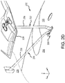
- FIG. 2D elements with like element numbering, as depicted in FIG. 2B and FIG. 2C , are intended to be the same and will not necessarily be repeated for the sake of clarity.
- a perspective view of link arm 256 in the stowed position (also referred to as a normal cruise mode) 292 and the deployed position (also referred to as a reverse thrust mode) 294 is illustrated, in accordance with various embodiments.
- a perspective view of blocker door 228 in the stowed position 292 and the deployed position 294 is illustrated, in accordance with various embodiments.
- fitting 200 may be flush with distal surface 204 when fitting 200 is in the installed position as illustrated in FIG. 2D .
- fitting 200 may be disposed radially inward of distal surface 204 when fitting 200 is in the installed position as illustrated in FIG. 2D .
- FIG. 3A and FIG. 3B elements with like element numbering, as depicted in FIG. 2B and FIG. 2C , are intended to be the same and will not necessarily be repeated for the sake of clarity.
- IFS 126 may comprise a distal layer 380 and a proximal layer 390.
- distal layer 380 may comprise a composite sheet or may comprise a metallic sheet.
- proximal layer 390 may comprise a composite sheet or may comprise a metallic sheet.
- Distal layer 380 may comprise a distal surface 204 and a proximal surface 382.
- Proximal layer 390 may comprise a distal surface 394 and a proximal surface 392.
- fitting 200 may include pivot 330 and retaining member 320.
- Retaining member 320 includes first end 326 and second end 328.
- Retaining member 320 includes lip 322 extending from retaining member 320 at second end 328. Lip 322 may extend in a direction substantially parallel to the centerline axis of gas turbine engine 110 (see FIG. 1 ). Lip 322 may extend in a direction substantially parallel to proximal surface 382 of IFS 126.
- linkage system 232 may include housing 310, fastener 312 and nut 314.
- housing 310 may be formed integrally with IFS 126.
- lip 322 may contact proximal surface 382 of IFS 126. Lip 322 may prevent second end 328 of retaining member 320 from moving relative to IFS 126.
- housing 310 may be formed separately from IFS 126. In this regard, lip 322 may contact proximal surface 316 of housing 310.
- housing 310 may be coupled to IFS 126 via an adhesive. In various embodiments, housing 310 may be coupled to IFS 126 via a fastener.
- housing 310 may be integrally formed with IFS 126 such as during a composite co-curing process.
- Housing 310 may encase a portion of retaining member 320.
- housing 310 may encase first end 326, second end 328, including lip 322 at proximal surface 316, and proximal surface 321 of retaining member 320.
- Fastener 312 may extend from housing 310. In various embodiments, fastener 312 may extend in a radial direction (y-direction in FIG. 3A ). Nut 314 may attach to fastener 312 to secure retaining member 320 to IFS 126. Nut 314 may retain first end 326 of retaining member 320 to IFS 126.
- Retaining member 320 may comprise a recess 324.
- Fastener 312 may be located at recess 324.
- Recess 324 may be configured to prevent nut 314 from extending into bypass flow path B.
- FIG. 3B a perspective, cross-section view of linkage system 232 in a deployed position 294 (also referred to as a reverse thrust mode) as well as in a stowed position 292 (also referred to as a forward thrust mode) is illustrated, in accordance with various embodiments.
- First end 252 of link arm 256 may comprise an aperture (also referred to herein as a second aperture) 304.
- retaining member 320 may define an aperture (also referred to herein as a first aperture) 402.
- Pivot 330 may extend through aperture 402. Pivot 330 may be coupled to retaining member 320 via aperture 402.
- Pivot 330 may extend through aperture 304 of link arm 256.
- Link arm 256 may be pivotally coupled to retaining member 320 via pivot 330.
- retaining member 320 may retain link arm 256 to housing 310.
- fitting 200 may retain link arm 256 to IFS 126.
- Retaining member 320 may define a cavity 342.
- cavity 342 may comprise a high aspect ratio aperture.
- a high aspect ratio aperture may comprise an aperture having an aspect ratio greater than 1.5, and in various embodiments, an aspect ratio greater than 2, and in various embodiments, an aspect ratio greater than 3, wherein aspect ratio, in this regard, refers to the ratio of the width of cavity 342 (measured along the z-direction in the xz-plane) and the height of cavity 342 (measured along the x-direction in the xz-plane).
- First end 252 of link arm 256 may be located within cavity 342.
- the aspect ratio of cavity 342 may be sized to accommodate rotation of link arm 256.
- FIG. 4 elements with like element numbering, as depicted in FIG. 3A and FIG. 3B , are intended to be the same and will not necessarily be repeated for the sake of clarity.
- FIG. 4A and FIG. 4B a perspective view and a side view of retaining member 320 being installed into housing 310 are illustrated, respectively, in accordance with various embodiments.
- An xyz-axes and a yz-axes are provided for ease of illustration.
- Link arm 256 is not shown in FIG. 4A for clarity purposes.
- Housing 310 may form a pocket 424. Lip 322 may be placed underneath or radially inward of distal layer 380. Lip 322 may be placed into pocket 424.
- Retaining member 320 may define an attachment aperture 406. Attachment aperture 406 may be placed over fastener 312. Similarly, retaining member 320 may define an attachment aperture 408. Attachment aperture 408 may be placed over fastener 412. Attachment aperture 408 may be similar to attachment aperture 406. Fastener 412 may be similar to fastener 312. Nut 314 may be threadingly coupled to fastener 312. Nut 414 may be threadingly coupled to fastener 412. Attachment aperture 406 and attachment aperture 404 may be located at first end 326 of retaining member 320. Attachment aperture 406 may comprise a high aspect ratio aperture. Attachment aperture 404 may comprise a high aspect ratio aperture. It is contemplated herein that similar arrangement of fasteners and nuts may be used instead of lip 322 at the forward end of retaining member 320.
- Pivot 600 may be similar to pivot 330 of FIGs. 3A through 4B .
- Pivot 600 may comprise a first portion 602 and a second portion 604.
- the first portion 602 may be threadingly coupled to the second portion 604.
- pivot 600 may comprise a bearing.
- pivot 600 may comprise a rod, pin, or the like.
- aperture 402 may extend in a direction substantially orthogonal to cavity 342.
- Aperture 304 may extend in a direction substantially orthogonal to cavity 342.
- Attachment aperture 406 and attachment aperture 408 may extend in a direction substantially orthogonal to aperture 402.
- fitting 200 may comprise a metal such as a steel alloy, stainless steel, titanium, aluminum, or any other metal.
- fitting 200 may comprise a composite material.
- Pivot 330 may comprise steel or stainless steel.
- pivot 330 may comprise aluminum.
- Pivot 330 may include a steel sleeve in response to pivot 330 comprising aluminum.
- Method 500 includes placing a pivot into a first aperture (step 510).
- Method 500 includes positioning the first aperture and a second aperture of a thrust reverser link arm in concentric alignment (step 520).
- Method 500 includes placing the pivot into the second aperture of the thrust reverser link arm (step 530).
- Method 500 includes placing a lip of a retaining member underneath a distal layer of an inner fixed structure (IFS) (step 540).
- Method 500 includes placing a fastening aperture disposed in a retaining member to surround a fastener (step 550).
- Method 500 includes fastening the retaining member to the fastener via a nut (step 560).
- step 510 may include placing pivot 330 into first aperture 402.
- Step 520 may include positioning aperture 402 and aperture 304 of link arm 256 in concentric alignment.
- Step 530 may include placing pivot 330 into aperture 304 of link arm 256.
- Step 540 may include placing lip 322 of retaining member 320 underneath, or radially inwards of, distal layer 380 of IFS 126.
- Step 550 may include placing fastening aperture 406 disposed in retaining member 320 to surround fastener 312.
- Step 560 may include fastening retaining member 320 to fastener 312 via nut 314, as illustrated in FIG. 3B .
- method 500 may be performed without having to open the thrust reverser blocker door 228 (see FIG. 2B ). In various embodiments, method 500 may be performed without having to access the core compartment 128 (see FIG. 1 ). In various embodiments, method 500 may be performed by accessing bypass flow path B (see FIG. 1 ).
Landscapes
- Engineering & Computer Science (AREA)
- Mechanical Engineering (AREA)
- General Engineering & Computer Science (AREA)
- Chemical & Material Sciences (AREA)
- Combustion & Propulsion (AREA)
- Structures Of Non-Positive Displacement Pumps (AREA)
- Wind Motors (AREA)
Claims (14)
- Verbindungssystem für eine Gondel (112) und eine innere feste Struktur (IFS) (126) einer Gondel (112), wobei das Verbindungssystem Folgendes umfasst:einen Drehpunkt (272; 330; 600), der derart konfiguriert ist, dass er sich durch eine zweite Öffnung (304) erstreckt, die in einem Verbindungsarm (256) angeordnet ist;ein Rückhalteelement (320), das ein erstes Ende (326) und ein zweites Ende (328) aufweist und eine erste Öffnung (402) und einen Hohlraum (342) definiert,wobei der Drehpunkt (272; 330; 600) derart konfiguriert ist, dass er sich zumindest teilweise in die erste Öffnung (402) erstreckt und der Hohlraum (342) derart konfiguriert ist, dass er einen Abschnitt des Verbindungsarms (256) unterbringt,dadurch gekennzeichnet, dass das Rückhalteelement (320) eine Anbringungsöffnung (406, 408), die sich an dem ersten Ende (326) befindet, und einen Rand (322) umfasst, der sich von dem Rückhalteelement (320) an dem zweiten Ende (328) erstreckt,wobei die Anbringungsöffnung (406, 408) derart konfiguriert ist, dass sie eine Befestigung (312, 412) aufnimmt und der Rand (322) derart konfiguriert ist, dass er unter einer distalen Schicht (380) der inneren festen Struktur (IFS) (126) platziert wird.
- Verbindungssystem und IFS nach Anspruch 1, wobei das erste Ende (326) des Rückhalteelements (320) derart konfiguriert ist, dass es über die Anbringungsöffnung (406, 408) an der IFS (126) angebracht ist.
- Verbindungssystem und IFS nach Anspruch 1 oder 2, wobei der Rand (322) derart konfiguriert ist, dass er verhindert, dass sich das zweite Ende (328) des Rückhalteelements (320) relativ zu der IFS (126) bewegt.
- Verbindungssystem und IFS nach Anspruch 1, 2 oder 3, ferner umfassend die Befestigung (312, 412), wobei die Anbringungsöffnung (406, 408) derart konfiguriert ist, dass sie die Befestigung (312, 412) aufnimmt.
- Verbindungssystem und IFS nach einem vorhergehenden Anspruch, wobei sich die erste Öffnung (402) in einer Richtung erstreckt, die im Wesentlichen orthogonal zu dem Hohlraum (342) ist.
- Verbindungssystem und IFS nach einem vorhergehenden Anspruch, wobei das Rückhalteelement (320) derart konfiguriert ist, dass es den Verbindungsarm (256) an der IFS (126) zurückhält.
- Verbindungssystem und IFS nach einem vorhergehenden Anspruch, wobei sich die Anbringungsöffnung (406, 408) im Wesentlichen orthogonal zu der ersten Öffnung (402) erstreckt.
- Verbindungssystem und IFS nach einem vorhergehenden Anspruch, wobei der Hohlraum (342) eine Öffnung umfasst, die ein Aspektverhältnis von mehr als 1,5 aufweist.
- Verbindungssystem und IFS nach einem vorhergehenden Anspruch, ferner umfassend ein Gehäuse (310), das derart konfiguriert ist, dass es einen Abschnitt des Rückhalteelements (320) einschließt, wobei das Gehäuse (310) an die IFS (126) gekoppelt ist und die Befestigung (312, 412) umfasst, die sich von dem Gehäuse (310) erstreckt, wobei die Anbringungsöffnung (406, 408) derart konfiguriert ist, dass sie die Befestigung (312, 412) aufnimmt.
- Gondel (112) für einen Gasturbinenmotor (110), umfassend:ein Verbindungssystem für eine Gondel (112) und eine IFS (126) einer Gondel (112) nach einem der Ansprüche 1 bis 9,wobei die IFS (126) eine proximale Schicht (390) und eine distale Schicht (380) umfasst;einen Verbindungsarm (256), der ein erstes Ende und ein zweites Ende aufweist, wobei eine zweite Öffnung (304) in dem Verbindungsarm (256) an dem ersten Ende angeordnet ist, wobei der Verbindungsarm (256) derart konfiguriert ist, dass er sich um die zweite Öffnung (304) dreht,wobei das Verbindungssystem eine Beschlaganordnung für den Verbindungsarm (256) umfasst,wobei sich der Drehpunkt (272; 330; 600) durch die zweite Öffnung (304) erstreckt,wobei sich der Drehpunkt (272; 330; 600) zumindest teilweise in die erste Öffnung (402) erstreckt und sich zumindest ein Abschnitt des ersten Endes des Verbindungsarms (256) innerhalb des Hohlraums (342) befindet,wobei sich der Rand (322) unter der distalen Schicht (380) der IFS (126) befindet, undwobei das Rückhalteelement (320) zumindest eines von radial einwärts der distalen Schicht (380) oder bündig mit der distalen Schicht (380) angeordnet ist.
- Gondel nach Anspruch 10, wobei die Beschlaganordnung ferner die Befestigung (312, 412) umfasst, wobei sich die Befestigung (312, 412) zumindest teilweise innerhalb der Anbringungsöffnung (406, 408) befindet.
- Gondel nach Anspruch 10 oder 11, wenn von Anspruch 7 abhängig, wobei das Gehäuse (310) einen Abschnitt des Rückhalteelements (320) einschließt, wobei das Gehäuse (310) an die IFS (126) gekoppelt ist und die Befestigung (312, 412) umfasst, die sich von dem Gehäuse (310) erstreckt, wobei sich die Befestigung (312, 412) durch die Anbringungsöffnung (406, 408) erstreckt.
- Verfahren zum Installieren eines Verbindungssystems an einer Gondel (112), umfassend:Platzieren eines Drehpunktes (272; 330; 600) zumindest teilweise innerhalb einer ersten Öffnung (402), die in einem Rückhalteelement (320) angeordnet ist,gekennzeichnet durchPositionieren der ersten Öffnung (402) und einer zweiten Öffnung (304), die in einem Schubumkehrerverbindungsarm (256) angeordnet ist, in konzentrischer Ausrichtung;Platzieren des Drehpunktes (272; 330; 600) zumindest teilweise in der zweiten Öffnung (304) des Schubumkehrerverbindungsarms (256) ;Platzieren eines Randes (322) unter einer distalen Schicht (380) einer inneren festen Struktur (IFS) (126), wobei sich der Rand (322) von dem Rückhalteelement (320) erstreckt, wobei das Rückhalteelement (320) zumindest einen Abschnitt der ersten Öffnung (402) definiert und zumindest einen Abschnitt eines Hohlraums definiert, wobei sich zumindest ein Abschnitt des Verbindungsarms (256) innerhalb des Hohlraums (342) befindet; undPlatzieren einer Befestigungsöffnung (406, 408), die in dem Rückhalteelement (320) angeordnet ist, sodass sie eine Befestigung (312, 412) umgibt, wobei die Befestigung (312, 412) an die IFS (126) gekoppelt ist,wobei das Verfahren von einem Umgehungsflussweg der Gondel (112) durchgeführt wird.
- Verfahren nach Anspruch 13, ferner umfassend: Befestigen des Rückhalteelements (320) an der Befestigung (312, 412) über eine Mutter (314, 414), wobei sich die Mutter (314, 414) radial einwärts einer distalen Fläche der distalen Schicht (380) befindet.
Applications Claiming Priority (1)
| Application Number | Priority Date | Filing Date | Title |
|---|---|---|---|
| US15/258,820 US10480453B2 (en) | 2016-09-07 | 2016-09-07 | Hidden thrust reverser blocker door link arm fitting |
Publications (2)
| Publication Number | Publication Date |
|---|---|
| EP3293388A1 EP3293388A1 (de) | 2018-03-14 |
| EP3293388B1 true EP3293388B1 (de) | 2019-10-02 |
Family
ID=59846358
Family Applications (1)
| Application Number | Title | Priority Date | Filing Date |
|---|---|---|---|
| EP17188628.6A Active EP3293388B1 (de) | 2016-09-07 | 2017-08-30 | Verdeckter schubumkehrerblockerklappenverbindungsarmbeschlag |
Country Status (2)
| Country | Link |
|---|---|
| US (1) | US10480453B2 (de) |
| EP (1) | EP3293388B1 (de) |
Families Citing this family (11)
| Publication number | Priority date | Publication date | Assignee | Title |
|---|---|---|---|---|
| US9689345B2 (en) * | 2015-06-10 | 2017-06-27 | Woodward, Inc. | Electric track lock |
| US10370111B2 (en) | 2016-09-07 | 2019-08-06 | United Technologies Corporation | Hidden thrust reverser blocker door link arm fitting |
| US10480453B2 (en) | 2016-09-07 | 2019-11-19 | United Technologies Corporation | Hidden thrust reverser blocker door link arm fitting |
| US10794328B2 (en) * | 2018-07-06 | 2020-10-06 | Rohr, Inc. | Thrust reverser with blocker door folding linkage |
| US11441514B2 (en) | 2018-10-02 | 2022-09-13 | Woodward, Inc. | Tertiary lock |
| US10865738B2 (en) | 2019-02-27 | 2020-12-15 | Woodward, Inc. | Traveling finger lock for an actuator |
| FR3107091B1 (fr) * | 2020-02-06 | 2022-01-07 | Safran Nacelles | Dispositif de fixation d’un pied de bielle de volet d’inversion de poussée à grilles |
| US11692509B2 (en) * | 2021-07-08 | 2023-07-04 | Rohr, Inc. | Hidden drag link for thrust reverser assembly |
| FR3125093A1 (fr) * | 2021-07-12 | 2023-01-13 | Safran Nacelles | Bielle pour nacelle de turbomachine |
| FR3137943A1 (fr) * | 2022-07-13 | 2024-01-19 | Safran Nacelles | Ensemble comprenant un panneau de nacelle et un organe formant liaison rotule |
| US11788490B1 (en) | 2022-12-05 | 2023-10-17 | Woodward, Inc. | Traveling finger lock for an actuator |
Family Cites Families (12)
| Publication number | Priority date | Publication date | Assignee | Title |
|---|---|---|---|---|
| US4605186A (en) | 1984-02-16 | 1986-08-12 | The Boeing Company | Vibration isolation device used with a jet engine thrust reverser unit |
| US5058828A (en) * | 1990-07-30 | 1991-10-22 | General Electric Company | Overwing thrust reverser |
| FR2756323B1 (fr) * | 1996-11-28 | 1998-12-31 | Hispano Suiza Sa | Dispositif de liaison d'un inverseur de poussee a un turbomoteur |
| US8109467B2 (en) | 2009-04-24 | 2012-02-07 | United Technologies Corporation | Thrust reverser assembly with shaped drag links |
| FR2958978B1 (fr) * | 2010-04-20 | 2014-04-18 | Aircelle Sa | Agencement de bielles de volets d'inversion de poussee sur la structure interne fixe d'une nacelle de turboreacteur |
| US10060390B2 (en) | 2012-02-29 | 2018-08-28 | United Technologies Corporation | Bypass duct with angled drag links |
| US9714612B2 (en) | 2013-10-04 | 2017-07-25 | Rohr, Inc. | Drag link fitting and vent combination |
| US10612490B2 (en) * | 2014-04-25 | 2020-04-07 | Rohr, Inc. | Drag link assembly including buried drag link fitting |
| GB201417202D0 (en) * | 2014-09-30 | 2014-11-12 | Rolls Royce Plc | Gas Turbine Engine Mounting Arrangement |
| US10024270B2 (en) | 2015-10-13 | 2018-07-17 | Rohr, Inc. | Vibration damping drag link fitting for a thrust reverser |
| US10370111B2 (en) | 2016-09-07 | 2019-08-06 | United Technologies Corporation | Hidden thrust reverser blocker door link arm fitting |
| US10480453B2 (en) | 2016-09-07 | 2019-11-19 | United Technologies Corporation | Hidden thrust reverser blocker door link arm fitting |
-
2016
- 2016-09-07 US US15/258,820 patent/US10480453B2/en active Active
-
2017
- 2017-08-30 EP EP17188628.6A patent/EP3293388B1/de active Active
Non-Patent Citations (1)
| Title |
|---|
| None * |
Also Published As
| Publication number | Publication date |
|---|---|
| US20180066607A1 (en) | 2018-03-08 |
| US10480453B2 (en) | 2019-11-19 |
| EP3293388A1 (de) | 2018-03-14 |
Similar Documents
| Publication | Publication Date | Title |
|---|---|---|
| EP3293388B1 (de) | Verdeckter schubumkehrerblockerklappenverbindungsarmbeschlag | |
| EP3293387B1 (de) | Versteckte schubumkehrvorrichtungsblocker-türverbindungsarmarmatur | |
| EP2243945B1 (de) | Schubumkehranordnung mit gekrümmten Schwenkhebeln | |
| US8904751B2 (en) | Thrust reverser assembly and method of operation | |
| US11149686B2 (en) | Thrust reverser assembly | |
| US11548652B2 (en) | Nacelle | |
| CA2997022A1 (en) | Thrust reverser assembly | |
| EP3236057B1 (de) | Blockertürverbindungsarm und -beschlag | |
| EP3361082B1 (de) | Versteifungsmerkmale einer schubumkehrklappe | |
| EP3236056B1 (de) | Blockertürverbindungsarm und -beschlag einer schubumkehrvorrichtung | |
| US20160025038A1 (en) | Pivot door thrust reverser | |
| US20190218999A1 (en) | Thrust reverser pivot door with extended forward edge |
Legal Events
| Date | Code | Title | Description |
|---|---|---|---|
| PUAI | Public reference made under article 153(3) epc to a published international application that has entered the european phase |
Free format text: ORIGINAL CODE: 0009012 |
|
| STAA | Information on the status of an ep patent application or granted ep patent |
Free format text: STATUS: THE APPLICATION HAS BEEN PUBLISHED |
|
| AK | Designated contracting states |
Kind code of ref document: A1 Designated state(s): AL AT BE BG CH CY CZ DE DK EE ES FI FR GB GR HR HU IE IS IT LI LT LU LV MC MK MT NL NO PL PT RO RS SE SI SK SM TR |
|
| AX | Request for extension of the european patent |
Extension state: BA ME |
|
| STAA | Information on the status of an ep patent application or granted ep patent |
Free format text: STATUS: REQUEST FOR EXAMINATION WAS MADE |
|
| 17P | Request for examination filed |
Effective date: 20180913 |
|
| RBV | Designated contracting states (corrected) |
Designated state(s): AL AT BE BG CH CY CZ DE DK EE ES FI FR GB GR HR HU IE IS IT LI LT LU LV MC MK MT NL NO PL PT RO RS SE SI SK SM TR |
|
| GRAP | Despatch of communication of intention to grant a patent |
Free format text: ORIGINAL CODE: EPIDOSNIGR1 |
|
| STAA | Information on the status of an ep patent application or granted ep patent |
Free format text: STATUS: GRANT OF PATENT IS INTENDED |
|
| INTG | Intention to grant announced |
Effective date: 20190402 |
|
| GRAS | Grant fee paid |
Free format text: ORIGINAL CODE: EPIDOSNIGR3 |
|
| GRAA | (expected) grant |
Free format text: ORIGINAL CODE: 0009210 |
|
| STAA | Information on the status of an ep patent application or granted ep patent |
Free format text: STATUS: THE PATENT HAS BEEN GRANTED |
|
| AK | Designated contracting states |
Kind code of ref document: B1 Designated state(s): AL AT BE BG CH CY CZ DE DK EE ES FI FR GB GR HR HU IE IS IT LI LT LU LV MC MK MT NL NO PL PT RO RS SE SI SK SM TR |
|
| REG | Reference to a national code |
Ref country code: GB Ref legal event code: FG4D |
|
| REG | Reference to a national code |
Ref country code: CH Ref legal event code: EP Ref country code: AT Ref legal event code: REF Ref document number: 1186435 Country of ref document: AT Kind code of ref document: T Effective date: 20191015 |
|
| REG | Reference to a national code |
Ref country code: IE Ref legal event code: FG4D |
|
| REG | Reference to a national code |
Ref country code: DE Ref legal event code: R096 Ref document number: 602017007438 Country of ref document: DE |
|
| REG | Reference to a national code |
Ref country code: NL Ref legal event code: MP Effective date: 20191002 |
|
| REG | Reference to a national code |
Ref country code: LT Ref legal event code: MG4D |
|
| REG | Reference to a national code |
Ref country code: AT Ref legal event code: MK05 Ref document number: 1186435 Country of ref document: AT Kind code of ref document: T Effective date: 20191002 |
|
| PG25 | Lapsed in a contracting state [announced via postgrant information from national office to epo] |
Ref country code: FI Free format text: LAPSE BECAUSE OF FAILURE TO SUBMIT A TRANSLATION OF THE DESCRIPTION OR TO PAY THE FEE WITHIN THE PRESCRIBED TIME-LIMIT Effective date: 20191002 Ref country code: PT Free format text: LAPSE BECAUSE OF FAILURE TO SUBMIT A TRANSLATION OF THE DESCRIPTION OR TO PAY THE FEE WITHIN THE PRESCRIBED TIME-LIMIT Effective date: 20200203 Ref country code: AT Free format text: LAPSE BECAUSE OF FAILURE TO SUBMIT A TRANSLATION OF THE DESCRIPTION OR TO PAY THE FEE WITHIN THE PRESCRIBED TIME-LIMIT Effective date: 20191002 Ref country code: NL Free format text: LAPSE BECAUSE OF FAILURE TO SUBMIT A TRANSLATION OF THE DESCRIPTION OR TO PAY THE FEE WITHIN THE PRESCRIBED TIME-LIMIT Effective date: 20191002 Ref country code: PL Free format text: LAPSE BECAUSE OF FAILURE TO SUBMIT A TRANSLATION OF THE DESCRIPTION OR TO PAY THE FEE WITHIN THE PRESCRIBED TIME-LIMIT Effective date: 20191002 Ref country code: SE Free format text: LAPSE BECAUSE OF FAILURE TO SUBMIT A TRANSLATION OF THE DESCRIPTION OR TO PAY THE FEE WITHIN THE PRESCRIBED TIME-LIMIT Effective date: 20191002 Ref country code: ES Free format text: LAPSE BECAUSE OF FAILURE TO SUBMIT A TRANSLATION OF THE DESCRIPTION OR TO PAY THE FEE WITHIN THE PRESCRIBED TIME-LIMIT Effective date: 20191002 Ref country code: LT Free format text: LAPSE BECAUSE OF FAILURE TO SUBMIT A TRANSLATION OF THE DESCRIPTION OR TO PAY THE FEE WITHIN THE PRESCRIBED TIME-LIMIT Effective date: 20191002 Ref country code: BG Free format text: LAPSE BECAUSE OF FAILURE TO SUBMIT A TRANSLATION OF THE DESCRIPTION OR TO PAY THE FEE WITHIN THE PRESCRIBED TIME-LIMIT Effective date: 20200102 Ref country code: GR Free format text: LAPSE BECAUSE OF FAILURE TO SUBMIT A TRANSLATION OF THE DESCRIPTION OR TO PAY THE FEE WITHIN THE PRESCRIBED TIME-LIMIT Effective date: 20200103 Ref country code: LV Free format text: LAPSE BECAUSE OF FAILURE TO SUBMIT A TRANSLATION OF THE DESCRIPTION OR TO PAY THE FEE WITHIN THE PRESCRIBED TIME-LIMIT Effective date: 20191002 Ref country code: NO Free format text: LAPSE BECAUSE OF FAILURE TO SUBMIT A TRANSLATION OF THE DESCRIPTION OR TO PAY THE FEE WITHIN THE PRESCRIBED TIME-LIMIT Effective date: 20200102 |
|
| PG25 | Lapsed in a contracting state [announced via postgrant information from national office to epo] |
Ref country code: HR Free format text: LAPSE BECAUSE OF FAILURE TO SUBMIT A TRANSLATION OF THE DESCRIPTION OR TO PAY THE FEE WITHIN THE PRESCRIBED TIME-LIMIT Effective date: 20191002 Ref country code: RS Free format text: LAPSE BECAUSE OF FAILURE TO SUBMIT A TRANSLATION OF THE DESCRIPTION OR TO PAY THE FEE WITHIN THE PRESCRIBED TIME-LIMIT Effective date: 20191002 Ref country code: IS Free format text: LAPSE BECAUSE OF FAILURE TO SUBMIT A TRANSLATION OF THE DESCRIPTION OR TO PAY THE FEE WITHIN THE PRESCRIBED TIME-LIMIT Effective date: 20200224 Ref country code: CZ Free format text: LAPSE BECAUSE OF FAILURE TO SUBMIT A TRANSLATION OF THE DESCRIPTION OR TO PAY THE FEE WITHIN THE PRESCRIBED TIME-LIMIT Effective date: 20191002 |
|
| PG25 | Lapsed in a contracting state [announced via postgrant information from national office to epo] |
Ref country code: AL Free format text: LAPSE BECAUSE OF FAILURE TO SUBMIT A TRANSLATION OF THE DESCRIPTION OR TO PAY THE FEE WITHIN THE PRESCRIBED TIME-LIMIT Effective date: 20191002 |
|
| REG | Reference to a national code |
Ref country code: DE Ref legal event code: R097 Ref document number: 602017007438 Country of ref document: DE |
|
| PG2D | Information on lapse in contracting state deleted |
Ref country code: IS |
|
| PG25 | Lapsed in a contracting state [announced via postgrant information from national office to epo] |
Ref country code: EE Free format text: LAPSE BECAUSE OF FAILURE TO SUBMIT A TRANSLATION OF THE DESCRIPTION OR TO PAY THE FEE WITHIN THE PRESCRIBED TIME-LIMIT Effective date: 20191002 Ref country code: RO Free format text: LAPSE BECAUSE OF FAILURE TO SUBMIT A TRANSLATION OF THE DESCRIPTION OR TO PAY THE FEE WITHIN THE PRESCRIBED TIME-LIMIT Effective date: 20191002 Ref country code: DK Free format text: LAPSE BECAUSE OF FAILURE TO SUBMIT A TRANSLATION OF THE DESCRIPTION OR TO PAY THE FEE WITHIN THE PRESCRIBED TIME-LIMIT Effective date: 20191002 Ref country code: IS Free format text: LAPSE BECAUSE OF FAILURE TO SUBMIT A TRANSLATION OF THE DESCRIPTION OR TO PAY THE FEE WITHIN THE PRESCRIBED TIME-LIMIT Effective date: 20200202 |
|
| PLBE | No opposition filed within time limit |
Free format text: ORIGINAL CODE: 0009261 |
|
| STAA | Information on the status of an ep patent application or granted ep patent |
Free format text: STATUS: NO OPPOSITION FILED WITHIN TIME LIMIT |
|
| PG25 | Lapsed in a contracting state [announced via postgrant information from national office to epo] |
Ref country code: SK Free format text: LAPSE BECAUSE OF FAILURE TO SUBMIT A TRANSLATION OF THE DESCRIPTION OR TO PAY THE FEE WITHIN THE PRESCRIBED TIME-LIMIT Effective date: 20191002 Ref country code: IT Free format text: LAPSE BECAUSE OF FAILURE TO SUBMIT A TRANSLATION OF THE DESCRIPTION OR TO PAY THE FEE WITHIN THE PRESCRIBED TIME-LIMIT Effective date: 20191002 Ref country code: SM Free format text: LAPSE BECAUSE OF FAILURE TO SUBMIT A TRANSLATION OF THE DESCRIPTION OR TO PAY THE FEE WITHIN THE PRESCRIBED TIME-LIMIT Effective date: 20191002 |
|
| 26N | No opposition filed |
Effective date: 20200703 |
|
| PG25 | Lapsed in a contracting state [announced via postgrant information from national office to epo] |
Ref country code: SI Free format text: LAPSE BECAUSE OF FAILURE TO SUBMIT A TRANSLATION OF THE DESCRIPTION OR TO PAY THE FEE WITHIN THE PRESCRIBED TIME-LIMIT Effective date: 20191002 |
|
| PG25 | Lapsed in a contracting state [announced via postgrant information from national office to epo] |
Ref country code: MC Free format text: LAPSE BECAUSE OF FAILURE TO SUBMIT A TRANSLATION OF THE DESCRIPTION OR TO PAY THE FEE WITHIN THE PRESCRIBED TIME-LIMIT Effective date: 20191002 |
|
| REG | Reference to a national code |
Ref country code: CH Ref legal event code: PL |
|
| PG25 | Lapsed in a contracting state [announced via postgrant information from national office to epo] |
Ref country code: CH Free format text: LAPSE BECAUSE OF NON-PAYMENT OF DUE FEES Effective date: 20200831 Ref country code: LI Free format text: LAPSE BECAUSE OF NON-PAYMENT OF DUE FEES Effective date: 20200831 Ref country code: LU Free format text: LAPSE BECAUSE OF NON-PAYMENT OF DUE FEES Effective date: 20200830 |
|
| REG | Reference to a national code |
Ref country code: BE Ref legal event code: MM Effective date: 20200831 |
|
| PG25 | Lapsed in a contracting state [announced via postgrant information from national office to epo] |
Ref country code: IE Free format text: LAPSE BECAUSE OF NON-PAYMENT OF DUE FEES Effective date: 20200830 Ref country code: BE Free format text: LAPSE BECAUSE OF NON-PAYMENT OF DUE FEES Effective date: 20200831 |
|
| PG25 | Lapsed in a contracting state [announced via postgrant information from national office to epo] |
Ref country code: TR Free format text: LAPSE BECAUSE OF FAILURE TO SUBMIT A TRANSLATION OF THE DESCRIPTION OR TO PAY THE FEE WITHIN THE PRESCRIBED TIME-LIMIT Effective date: 20191002 Ref country code: MT Free format text: LAPSE BECAUSE OF FAILURE TO SUBMIT A TRANSLATION OF THE DESCRIPTION OR TO PAY THE FEE WITHIN THE PRESCRIBED TIME-LIMIT Effective date: 20191002 Ref country code: CY Free format text: LAPSE BECAUSE OF FAILURE TO SUBMIT A TRANSLATION OF THE DESCRIPTION OR TO PAY THE FEE WITHIN THE PRESCRIBED TIME-LIMIT Effective date: 20191002 |
|
| PG25 | Lapsed in a contracting state [announced via postgrant information from national office to epo] |
Ref country code: MK Free format text: LAPSE BECAUSE OF FAILURE TO SUBMIT A TRANSLATION OF THE DESCRIPTION OR TO PAY THE FEE WITHIN THE PRESCRIBED TIME-LIMIT Effective date: 20191002 |
|
| REG | Reference to a national code |
Ref country code: DE Ref legal event code: R081 Ref document number: 602017007438 Country of ref document: DE Owner name: RAYTHEON TECHNOLOGIES CORPORATION (N.D.GES.D.S, US Free format text: FORMER OWNER: UNITED TECHNOLOGIES CORPORATION, FARMINGTON, CONN., US |
|
| P01 | Opt-out of the competence of the unified patent court (upc) registered |
Effective date: 20230520 |
|
| PGFP | Annual fee paid to national office [announced via postgrant information from national office to epo] |
Ref country code: GB Payment date: 20230720 Year of fee payment: 7 |
|
| PGFP | Annual fee paid to national office [announced via postgrant information from national office to epo] |
Ref country code: FR Payment date: 20230720 Year of fee payment: 7 Ref country code: DE Payment date: 20230720 Year of fee payment: 7 |