EP2060737A1 - Cylinder assembly for a reciprocating compressor combustion machine and reciprocating compressor combustion machine - Google Patents
Cylinder assembly for a reciprocating compressor combustion machine and reciprocating compressor combustion machine Download PDFInfo
- Publication number
- EP2060737A1 EP2060737A1 EP07120774A EP07120774A EP2060737A1 EP 2060737 A1 EP2060737 A1 EP 2060737A1 EP 07120774 A EP07120774 A EP 07120774A EP 07120774 A EP07120774 A EP 07120774A EP 2060737 A1 EP2060737 A1 EP 2060737A1
- Authority
- EP
- European Patent Office
- Prior art keywords
- piston
- cylinder
- combustion chamber
- flow
- pressure chamber
- Prior art date
- Legal status (The legal status is an assumption and is not a legal conclusion. Google has not performed a legal analysis and makes no representation as to the accuracy of the status listed.)
- Withdrawn
Links
- 238000002485 combustion reaction Methods 0.000 title claims abstract description 156
- 230000002093 peripheral effect Effects 0.000 claims description 10
- 239000000295 fuel oil Substances 0.000 claims description 7
- 239000003502 gasoline Substances 0.000 claims description 6
- 238000012856 packing Methods 0.000 claims description 3
- 239000007789 gas Substances 0.000 description 62
- 230000006835 compression Effects 0.000 description 12
- 238000007906 compression Methods 0.000 description 12
- 239000000446 fuel Substances 0.000 description 9
- 238000007373 indentation Methods 0.000 description 4
- 239000000203 mixture Substances 0.000 description 4
- MWUXSHHQAYIFBG-UHFFFAOYSA-N nitrogen oxide Inorganic materials O=[N] MWUXSHHQAYIFBG-UHFFFAOYSA-N 0.000 description 3
- 230000015572 biosynthetic process Effects 0.000 description 2
- 238000010276 construction Methods 0.000 description 2
- 238000013461 design Methods 0.000 description 2
- 230000002000 scavenging effect Effects 0.000 description 2
- 230000003321 amplification Effects 0.000 description 1
- 238000013459 approach Methods 0.000 description 1
- 239000002551 biofuel Substances 0.000 description 1
- 150000001875 compounds Chemical class 0.000 description 1
- 230000003247 decreasing effect Effects 0.000 description 1
- 230000001419 dependent effect Effects 0.000 description 1
- 230000001627 detrimental effect Effects 0.000 description 1
- 239000002283 diesel fuel Substances 0.000 description 1
- 230000000694 effects Effects 0.000 description 1
- 239000003344 environmental pollutant Substances 0.000 description 1
- 239000010763 heavy fuel oil Substances 0.000 description 1
- 238000003199 nucleic acid amplification method Methods 0.000 description 1
- 239000003921 oil Substances 0.000 description 1
- 231100000719 pollutant Toxicity 0.000 description 1
- 238000010926 purge Methods 0.000 description 1
- 238000004088 simulation Methods 0.000 description 1
- 238000012546 transfer Methods 0.000 description 1
- XLYOFNOQVPJJNP-UHFFFAOYSA-N water Substances O XLYOFNOQVPJJNP-UHFFFAOYSA-N 0.000 description 1
Images


Classifications
-
- F—MECHANICAL ENGINEERING; LIGHTING; HEATING; WEAPONS; BLASTING
- F01—MACHINES OR ENGINES IN GENERAL; ENGINE PLANTS IN GENERAL; STEAM ENGINES
- F01B—MACHINES OR ENGINES, IN GENERAL OR OF POSITIVE-DISPLACEMENT TYPE, e.g. STEAM ENGINES
- F01B7/00—Machines or engines with two or more pistons reciprocating within same cylinder or within essentially coaxial cylinders
- F01B7/18—Machines or engines with two or more pistons reciprocating within same cylinder or within essentially coaxial cylinders with differential piston
-
- F—MECHANICAL ENGINEERING; LIGHTING; HEATING; WEAPONS; BLASTING
- F02—COMBUSTION ENGINES; HOT-GAS OR COMBUSTION-PRODUCT ENGINE PLANTS
- F02B—INTERNAL-COMBUSTION PISTON ENGINES; COMBUSTION ENGINES IN GENERAL
- F02B19/00—Engines characterised by precombustion chambers
- F02B19/02—Engines characterised by precombustion chambers the chamber being periodically isolated from its cylinder
- F02B19/04—Engines characterised by precombustion chambers the chamber being periodically isolated from its cylinder the isolation being effected by a protuberance on piston or cylinder head
-
- F—MECHANICAL ENGINEERING; LIGHTING; HEATING; WEAPONS; BLASTING
- F02—COMBUSTION ENGINES; HOT-GAS OR COMBUSTION-PRODUCT ENGINE PLANTS
- F02B—INTERNAL-COMBUSTION PISTON ENGINES; COMBUSTION ENGINES IN GENERAL
- F02B19/00—Engines characterised by precombustion chambers
- F02B19/08—Engines characterised by precombustion chambers the chamber being of air-swirl type
-
- F—MECHANICAL ENGINEERING; LIGHTING; HEATING; WEAPONS; BLASTING
- F02—COMBUSTION ENGINES; HOT-GAS OR COMBUSTION-PRODUCT ENGINE PLANTS
- F02B—INTERNAL-COMBUSTION PISTON ENGINES; COMBUSTION ENGINES IN GENERAL
- F02B23/00—Other engines characterised by special shape or construction of combustion chambers to improve operation
- F02B23/02—Other engines characterised by special shape or construction of combustion chambers to improve operation with compression ignition
- F02B23/06—Other engines characterised by special shape or construction of combustion chambers to improve operation with compression ignition the combustion space being arranged in working piston
- F02B23/0618—Other engines characterised by special shape or construction of combustion chambers to improve operation with compression ignition the combustion space being arranged in working piston having in-cylinder means to influence the charge motion
- F02B23/0624—Swirl flow
-
- F—MECHANICAL ENGINEERING; LIGHTING; HEATING; WEAPONS; BLASTING
- F02—COMBUSTION ENGINES; HOT-GAS OR COMBUSTION-PRODUCT ENGINE PLANTS
- F02B—INTERNAL-COMBUSTION PISTON ENGINES; COMBUSTION ENGINES IN GENERAL
- F02B23/00—Other engines characterised by special shape or construction of combustion chambers to improve operation
- F02B23/02—Other engines characterised by special shape or construction of combustion chambers to improve operation with compression ignition
- F02B23/06—Other engines characterised by special shape or construction of combustion chambers to improve operation with compression ignition the combustion space being arranged in working piston
- F02B23/0618—Other engines characterised by special shape or construction of combustion chambers to improve operation with compression ignition the combustion space being arranged in working piston having in-cylinder means to influence the charge motion
- F02B23/0627—Other engines characterised by special shape or construction of combustion chambers to improve operation with compression ignition the combustion space being arranged in working piston having in-cylinder means to influence the charge motion having additional bores or grooves machined into the piston for guiding air or charge flow to the piston bowl
-
- F—MECHANICAL ENGINEERING; LIGHTING; HEATING; WEAPONS; BLASTING
- F02—COMBUSTION ENGINES; HOT-GAS OR COMBUSTION-PRODUCT ENGINE PLANTS
- F02B—INTERNAL-COMBUSTION PISTON ENGINES; COMBUSTION ENGINES IN GENERAL
- F02B23/00—Other engines characterised by special shape or construction of combustion chambers to improve operation
- F02B23/02—Other engines characterised by special shape or construction of combustion chambers to improve operation with compression ignition
- F02B23/06—Other engines characterised by special shape or construction of combustion chambers to improve operation with compression ignition the combustion space being arranged in working piston
- F02B23/0618—Other engines characterised by special shape or construction of combustion chambers to improve operation with compression ignition the combustion space being arranged in working piston having in-cylinder means to influence the charge motion
- F02B23/063—Other engines characterised by special shape or construction of combustion chambers to improve operation with compression ignition the combustion space being arranged in working piston having in-cylinder means to influence the charge motion the combustion space in the piston interacting fluid dynamically with the cylinder head, the injector body or the cylinder wall
-
- F—MECHANICAL ENGINEERING; LIGHTING; HEATING; WEAPONS; BLASTING
- F02—COMBUSTION ENGINES; HOT-GAS OR COMBUSTION-PRODUCT ENGINE PLANTS
- F02B—INTERNAL-COMBUSTION PISTON ENGINES; COMBUSTION ENGINES IN GENERAL
- F02B23/00—Other engines characterised by special shape or construction of combustion chambers to improve operation
- F02B23/02—Other engines characterised by special shape or construction of combustion chambers to improve operation with compression ignition
- F02B23/06—Other engines characterised by special shape or construction of combustion chambers to improve operation with compression ignition the combustion space being arranged in working piston
- F02B23/0678—Unconventional, complex or non-rotationally symmetrical shapes of the combustion space, e.g. flower like, having special shapes related to the orientation of the fuel spray jets
- F02B23/0687—Multiple bowls in the piston, e.g. one bowl per fuel spray jet
-
- F—MECHANICAL ENGINEERING; LIGHTING; HEATING; WEAPONS; BLASTING
- F02—COMBUSTION ENGINES; HOT-GAS OR COMBUSTION-PRODUCT ENGINE PLANTS
- F02B—INTERNAL-COMBUSTION PISTON ENGINES; COMBUSTION ENGINES IN GENERAL
- F02B33/00—Engines characterised by provision of pumps for charging or scavenging
- F02B33/02—Engines with reciprocating-piston pumps; Engines with crankcase pumps
- F02B33/06—Engines with reciprocating-piston pumps; Engines with crankcase pumps with reciprocating-piston pumps other than simple crankcase pumps
- F02B33/10—Engines with reciprocating-piston pumps; Engines with crankcase pumps with reciprocating-piston pumps other than simple crankcase pumps with the pumping cylinder situated between working cylinder and crankcase, or with the pumping cylinder surrounding working cylinder
- F02B33/14—Engines with reciprocating-piston pumps; Engines with crankcase pumps with reciprocating-piston pumps other than simple crankcase pumps with the pumping cylinder situated between working cylinder and crankcase, or with the pumping cylinder surrounding working cylinder working and pumping pistons forming stepped piston
-
- F—MECHANICAL ENGINEERING; LIGHTING; HEATING; WEAPONS; BLASTING
- F02—COMBUSTION ENGINES; HOT-GAS OR COMBUSTION-PRODUCT ENGINE PLANTS
- F02B—INTERNAL-COMBUSTION PISTON ENGINES; COMBUSTION ENGINES IN GENERAL
- F02B2275/00—Other engines, components or details, not provided for in other groups of this subclass
- F02B2275/14—Direct injection into combustion chamber
-
- F—MECHANICAL ENGINEERING; LIGHTING; HEATING; WEAPONS; BLASTING
- F02—COMBUSTION ENGINES; HOT-GAS OR COMBUSTION-PRODUCT ENGINE PLANTS
- F02B—INTERNAL-COMBUSTION PISTON ENGINES; COMBUSTION ENGINES IN GENERAL
- F02B2275/00—Other engines, components or details, not provided for in other groups of this subclass
- F02B2275/40—Squish effect
-
- F—MECHANICAL ENGINEERING; LIGHTING; HEATING; WEAPONS; BLASTING
- F02—COMBUSTION ENGINES; HOT-GAS OR COMBUSTION-PRODUCT ENGINE PLANTS
- F02B—INTERNAL-COMBUSTION PISTON ENGINES; COMBUSTION ENGINES IN GENERAL
- F02B23/00—Other engines characterised by special shape or construction of combustion chambers to improve operation
- F02B23/02—Other engines characterised by special shape or construction of combustion chambers to improve operation with compression ignition
- F02B23/06—Other engines characterised by special shape or construction of combustion chambers to improve operation with compression ignition the combustion space being arranged in working piston
- F02B23/0672—Omega-piston bowl, i.e. the combustion space having a central projection pointing towards the cylinder head and the surrounding wall being inclined towards the cylinder center axis
-
- Y—GENERAL TAGGING OF NEW TECHNOLOGICAL DEVELOPMENTS; GENERAL TAGGING OF CROSS-SECTIONAL TECHNOLOGIES SPANNING OVER SEVERAL SECTIONS OF THE IPC; TECHNICAL SUBJECTS COVERED BY FORMER USPC CROSS-REFERENCE ART COLLECTIONS [XRACs] AND DIGESTS
- Y02—TECHNOLOGIES OR APPLICATIONS FOR MITIGATION OR ADAPTATION AGAINST CLIMATE CHANGE
- Y02T—CLIMATE CHANGE MITIGATION TECHNOLOGIES RELATED TO TRANSPORTATION
- Y02T10/00—Road transport of goods or passengers
- Y02T10/10—Internal combustion engine [ICE] based vehicles
- Y02T10/12—Improving ICE efficiencies
Definitions
- the invention relates to a cylinder arrangement for a reciprocating internal combustion engine, in particular for a two-stroke or four-stroke diesel engine, gasoline engine or gas engine, in particular for a two-stroke large diesel engine for combustion of heavy oil, and a reciprocating internal combustion engine with a cylinder arrangement according to the preamble of the independent claims 1 and 14.
- the fresh air is introduced by means of a Aufladexx, which is usually designed as an exhaust gas turbocharger under elevated pressure in the combustion chamber of a cylinder.
- a Aufladeoli which is usually designed as an exhaust gas turbocharger under elevated pressure in the combustion chamber of a cylinder.
- the hot exhaust gases are supplied by opening an exhaust valve from the combustion chamber of the cylinder of Aufladeenstein.
- the charging group consists essentially of a turbine, which passes through the hot exhaust gases entering under pressure in the charging group is driven. The turbine in turn drives a compressor, whereby fresh air is sucked in and compressed.
- the compressor with turbine an arrangement which is often referred to simply as a turbocharger and especially, but not only, used in the case of two-stroke large diesel engines, a centrifugal compressor, a so-called diffuser, a charge air cooler, a water separator and an inlet receiver downstream, from where the compressed fresh air, also referred to as charge air or purge air, is finally fed into the individual combustion chambers of the cylinder of the large diesel engine.
- a charging group can thus increase the supply of fresh air and increase the efficiency of the combustion process in the combustion chamber of the cylinder.
- the supply of air into the combustion chamber can be done at different locations on the cylinder.
- the air is introduced into the combustion chamber of the cylinder via scavenging slots which are arranged in the running surface in the lower region of the cylinder.
- This principle is both for example in small two-wheeled engines, the operated with a gasoline-oil mixture and small power from 1 KW up to a few KW have long been known and comes even with the enormously powerful two-stroke large diesel engines, which are usually fueled with heavy oil, used successfully for many decades.
- the charge air is usually introduced via one or more intake valves, which are arranged in the cylinder cover into the combustion chamber of the cylinder.
- two-stroke engines are quite well known, which are equipped instead of scavenging slots in the lower part of the cylinder with intake valves in the cylinder cover.
- a certain turbulence level in the cylinder is to be strived for, so that optimum mixing or turbulence of the air-fuel mixture is achieved, so that the combustion takes place under optimized conditions ultimately contributes to increasing performance and efficiency.
- fuel consumption at a given power can be optimized, but also the formation of combustion exhaust gases can be positively influenced in addition to other measures, eg by the formation harmful gases, such as the dreaded nitrogen oxides, reduced or even prevented.
- FIG. 1a schematically the upper part of a cylinder of a longitudinally-flushed two-stroke engine is shown, which can be operated in particular with diesel fuel.
- cylinder 2 ' Shown is a cylinder 2 ', in which cylinder 2' is a piston 3 'in the compression stroke in the vicinity of the top dead center OT' is.
- the cylinder cover 4 ', the cylinder wall 5' and the piston top 6 'of the piston 3' define a combustion chamber 7 '.
- the piston 3 ' has in the region of the center of the piston surface 6' a recess which extends in the direction of the cylinder cover 4 'away, and so together with a corresponding recess in the cylinder cover 4', which extends in the region of the exhaust valve A ', a Partial combustion chamber 11 'forms.
- the indentation in the piston surface 6 ' may also be absent or the piston surface 6' may also be arched outwards in the direction of the cylinder cover 4 '.
- the partial surface 61 'of the piston surface 6' is referred to as "pinch surface 61 '" and the boundary edge 62', which the pinch surface 61 'to Boundary in the piston surface 6 'out limited, the expert knows as a "pinch edge 62'".
- the pinch edge 62 ' is thus formed between the piston surface 6' and pinch surface 61 ', and serves to accelerate the charge air, which is generated by compression of the space between pinch surface 61' and piston surface 6 'by the compression movement of the piston 3', in the partial combustion chamber eleventh ', whereby a turbulence and a corresponding swirl of the gases in the cylinder, so for example the air or an air-fuel mixture is generated.
- the pinch surface 61 'on the piston 6' is here as well as the corresponding counter surface on the cylinder cover 4 'substantially smooth, so that with respect to the circumferential direction of the pinch edge 62' a more or less uniform gas flow from between the cylinder cover 4 'and pinch surface 61' formed Quetschvolumen out into the partial combustion chamber 11 'is generated.
- Fig. 1a is a section along the section line I'-I 'according to Fig. 1b showing the piston 3 'in plan view of the surface 3' with pinch surface 61 ', pinch edge 62' and the indentation in the piston surface to form the partial combustion chamber 11 '.
- the object of the invention is therefore to provide an improved cylinder arrangement for a reciprocating internal combustion engine, in particular for a two-stroke or four-stroke diesel engine, gasoline engine or gas engine, in particular for a two-stroke large diesel engine for combustion of heavy oil, and a reciprocating internal combustion engine with such a cylinder arrangement available in which the charge movement of the gases provided in the cylinder for combustion and the turbulence associated with the charge movement is optimized, wherein in particular a significantly higher level of turbulence can be achieved and the turbulence distribution in the combustion chamber can be selectively adjusted.
- the invention thus relates to a cylinder arrangement for a reciprocating internal combustion engine with at least one cylinder, in which cylinder a piston between a top dead center and a bottom dead center is arranged back and forth.
- a combustion chamber comprising a partial combustion chamber, wherein the combustion chamber is sealed against a lower side of the piston by a piston ring packing comprising at least one piston ring.
- a pressure chamber and a flow channel are provided for forming a gas flow between the pressure chamber and the partial combustion chamber.
- Essential for the invention is thus that within the cylinder, that is, either inside or outside the combustion chamber, a pressure chamber is created in which in the operating state of the reciprocating internal combustion engine, at least during a compression stroke of the piston and / or at least in the region of the top dead center of the piston movement another gas pressure, in particular a higher gas pressure is provided by the movement of the piston, as that gas pressure prevailing in the partial combustion chamber ,
- a pressure chamber is created in which in the operating state of the reciprocating internal combustion engine, at least during a compression stroke of the piston and / or at least in the region of the top dead center of the piston movement another gas pressure, in particular a higher gas pressure is provided by the movement of the piston, as that gas pressure prevailing in the partial combustion chamber .
- the better mixing of the gases in the cylinder is achieved in that a gas volume in the pressure chamber by the movement of the piston at least in the vicinity of the top dead center of the piston movement completely or partially pinched off and / or reduced or compressed, wherein the percentage change or Compression of this volume in the pressure chamber due to the movement of the piston is greater than the corresponding volume change or compression in the partial combustion chamber.
- the flow velocity of the gases with suitable dimensioning of the pressure chamber and / or the flow line and / or the partial combustion chamber quite close to the speed of sound, so that particularly strong turbulence can be generated in the partial combustion chamber.
- the piston is designed as a stepped piston with a base piston and a piston head such that the stepped piston cooperates with a step-shaped recess in the cylinder cover in such a way that in an operating state in the vicinity of the top dead center of the pressure chamber is formed in the form of a variable volume annular space between the piston head and the cylinder wall. That is, the pressure chamber is near the top dead center, apart from the connection via the flow channel, spatially separated from the partial combustion chamber.
- the volume of the pressure space thus formed is preferably significantly smaller than the volume of the partial combustion chamber, the percentage change in the volume of the pressure chamber due to the compression movement of the piston is greater than the corresponding change in the volume of the partial combustion chamber, so that in the pressure chamber compared to the partial combustion chamber higher gas pressure is created, whereby a gas flow is built up from the pressure chamber via the flow channel in the partial combustion chamber.
- the flow channel can be formed, for example, by a flow gap between a peripheral surface of the stepped piston and the cylinder wall, in particular between a peripheral surface of the piston head and the cylinder wall.
- the flow channel is formed as a flow groove or flow groove on the outer peripheral surface of the piston head and / or the flow channel is formed for example as a flow groove in the cylinder wall.
- the flow channel can also be formed as a flow line between the annulus and the partial combustion chamber, wherein the flow line can be advantageously performed by the cylinder wall and / or by the cylinder cover and / or by the stepped piston.
- These special embodiments with tubular flow channels, which are guided through the piston and / or through the cylinder wall and / or through the cylinder cover, are particularly suitable for directing the gas flow to specific locations within the combustion chamber or the partial combustion chamber, and so on eg To generate turbulence at predefinable locations and / or with predeterminable geometries in the combustion chamber.
- a surface of the piston head facing the cylinder cover can be shaped in a suitable manner.
- this surface of the piston head may also have an indentation directed away from the cylinder cover, or may face the cylinder cover Own bulge.
- complicated shaped piston surfaces where, for example, indentations and bulges are combined, are possible. This of course applies to all piston surfaces of cylinder arrangements according to the present invention, in which such special designs of the cylinder surface can be advantageously provided.
- the partial combustion chamber is designed as a combustion chamber recess in the piston such that the piston cooperates with a projection of the cylinder cover projecting into the combustion chamber in such a way that in an operating state in the vicinity of top dead center the pressure chamber can be varied in volume Pressure space between the cylinder cover and the piston surface of the piston is formed. That is, the pressure chamber is now not formed below the piston surface, adjacent to the piston between the cylinder wall and a peripheral surface of the piston, but above the piston between a predetermined range of the piston surface and a corresponding surface area of the cylinder cover.
- the flow channel is preferably designed as a flow line between the pressure chamber and the partial combustion chamber configured as a combustion chamber recess, wherein the flow line is preferably guided through the cylinder cover and / or through the stepped piston.
- the flow channel is formed as a flow groove on a peripheral surface of the combustion chamber recess on the piston, or that the flow channel is formed as a flow groove on a circumferential surface of the projection of the cylinder cover.
- the pressure space and the flow channel for forming a gas flow between the pressure space and the partial combustion space are provided as a recess in the surface of the piston.
- the pressure space is not spatial separated from the partial combustion chamber, but the pressure chamber is only separated from the partial combustion chamber with respect to the gas pressure level. Rather, during the compression movement of the piston, gas is additionally pressed into the pressure space designed as a surface recess, whereby a pressure which is increased in comparison with the partial combustion space is produced in the pressure space, which in turn results in a gas flow from the pressure space via the flow passage into the partial combustion space.
- pressure chamber and the flow channel to form a gas flow between the pressure chamber and the partial combustion chamber can be provided in another embodiment, as a recess in a combustion chamber facing surface of the cylinder cover.
- the reciprocating internal combustion engine equipped with a cylinder arrangement according to the invention is a two-stroke or four-stroke internal combustion engine, in particular a two-stroke or four-stroke diesel engine, gasoline engine or gas engine, in particular a two-stroke large diesel engine for burning heavy fuel oil.
- the invention relates in addition to the cylinder arrangement as such, also a reciprocating internal combustion engine, in particular a two-stroke or four-stroke diesel engine, gasoline engine or gas engine, in particular a two-stroke large diesel engine for combustion of heavy oil, with an inventive cylinder assembly.
- a reciprocating internal combustion engine in particular a two-stroke or four-stroke diesel engine, gasoline engine or gas engine, in particular a two-stroke large diesel engine for combustion of heavy oil, with an inventive cylinder assembly.
- FIG. 1a and Fig. 1b show by way of explanation a known prior art.
- the reference numerals in FIG Fig. 1a and 1b provided with an apostrophe, while the reference numerals in the remaining figures, all of which relate to the invention, do not wear an apostrophe. Because the Fig. 1a and 1b already discussed in detail at the beginning, there is no need for further discussion here.
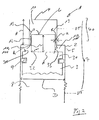
- Fig. 2 shows in a highly schematic representation of a very simple embodiment of an inventive cylinder assembly, which is hereinafter referred to collectively with the reference numeral 1.
- the inventive cylinder assembly 1 is provided for use in a reciprocating internal combustion engine, comprising at least one cylinder 2 with diameter D, in which cylinder 2, a piston 3 between a top dead center OT and a bottom dead center UT back and forth arranged.
- a combustion chamber 7 In the cylinder 2 is bounded by a cylinder cover 4, a cylinder wall 5, and a piston surface 6 of the piston 3, a combustion chamber 7, wherein the combustion chamber 7 comprises at least a partial combustion chamber 11.
- the combustion chamber 7 is sealed against an underside 8 of the piston 3 in a manner known per se by a piston ring packing comprising at least one piston ring 9.
- Fig. 2 mainly the inventive principle is to be explained that is applicable in its specific embodiments for both Zweittaktals for four-stroke engines and both for self-igniting engines, such as diesel engines and for motors application, for example, be ignited via an ignition means such as a spark plug.
- the invention is suitable for use in engines with and without gas exchange valves, ie with and without inlet and / or exhaust valves.
- a pressure chamber 10, 100 and a flow channel 12 for forming a gas flow 13 between the pressure chamber 10, 100 and the partial combustion chamber 11 are provided.
- a stepped piston 30 with a base piston 31 and a piston head 32 of width d and the Height h formed.
- a stepped recess 40 of the height H is provided, which is designed such that the stepped piston 30 with the step-shaped recess 40 in the cylinder cover 4 cooperates such that in the vicinity of the top dead center TDC of the pressure chamber 10 in the form of a variable in volume Annular space 100 between the piston head 32, a surface 310 of the base piston and the cylinder wall 5 is formed.
- the flow channel 12 is formed by a flow gap 12 of the width a between a peripheral surface 33 of the piston head 32 and the cylinder wall 5.
- the piston 3 moves in the compression stroke in the direction of the top dead center TDC, as soon as the piston head 32 enters the recess 40 of the cylinder cover, the pressure chamber 10 as annular space 100 and the partial combustion chamber 11 formed and spatially separated from each other.
- the gas trapped in the annular space 100 and in the partial combustion space 11, ie, for example, is removed. the charge air, each compressed differently.
- the percentage change in the volume of the annular space 100 as a function of the crank angle is greater than the corresponding percentage change in the volume of the partial combustion chamber 11. Therefore, with increasing compression in the annulus 100, a greater pressure builds up than in the partial combustion chamber 11. This results via the flow channel 12th who in the example of the Fig. 2 is formed simply by the circumferential gap surface between the piston head 32 and the cylinder wall 5, a compensation flow 13 from the annulus 100 in the partial combustion chamber 11, whereby in the partial combustion chamber 11 corresponding strong turbulence arise, which guarantee a correspondingly good mixing in the partial combustion chamber 11, so that, for example injected fuel is significantly better with the charge air swirled or mixed, as is known from the cylinder arrangements of the prior art.
- Fig. 3a is a second embodiment shown schematically with stepped piston.
- the cylinder 3 with stepped piston 30 belongs to a longitudinally-flushed two-stroke large diesel engine is operated with heavy oil as fuel.
- an exhaust valve V is arranged centrally.
- the also arranged in the cylinder head injectors are in the sectional view of the Fig. 3a not to be seen.
- Fig. 3b On the outer circumferential surface 33 of the piston head 32 flow grooves 12 are incorporated, through which the charge air flows from the annulus 100 under elevated gas pressure in the partial combustion chamber 11 and is pressed.
- the flow grooves 12 have a curved course, whereby the charge air flowing through the flow grooves 12 with respect to a longitudinal axis of the stepped piston 30 receives an additional twist, so that the charge air in the partial combustion chamber 11 even better swirled.
- the flow grooves 12 may also have a non-curved course or some of the flow grooves 12 may have a curved course and on one and the same stepped piston 30 other flow grooves 12 another curved course or eg with respect to the longitudinal axis of the piston 30 a straight course.
- the person skilled in the art knows how the exact configuration of the flow grooves 12 can be suitably adapted to the specific requirements.
- Fig. 4 is a third embodiment shown with stepped piston and flow line.
- the embodiment of Fig. 4 is different from the one of Fig. 3a or 3b in that the flow channel 12 is not formed as a flow groove 12, but as a flow line 12 between the annulus 100 and the partial combustion chamber 11.
- the Fig. 4 two different flow lines 12 are provided.
- the flow line 12 in the illustration according to the left part of the cylinder assembly 1 is guided as a bore 12 through the interior of the piston head 32, while the second flow line 12 is guided in the representation of the right part of the cylinder assembly 1 as a bore 12 through the cylinder wall 5 and the cylinder cover 4.
- This guidance of the flow line 12 is particularly suitable for transporting the gas flow 13 from the annular space 100 into the partial combustion chamber 11 very selectively to a predeterminable location in the partial combustion space 11 and, moreover, is particularly suitable for generating turbulence with a predefinable geometry. For example, to generate a toroidal geometry in the center of the partial combustion chamber 11.
- FIG. 5 a first embodiment of an inventive cylinder assembly 1 with a combustion chamber 1100 is shown in a schematic manner.
- the partial combustion chamber 11 is in the embodiment according to Fig. 6 as a combustion chamber recess 1100 in the piston 3 is formed such that the piston 3 cooperates with a projecting into the combustion chamber 7 projection 400 of the cylinder cover 4 so that in an operating state in the vicinity of the top dead center OT the pressure chamber 10 in the form of a variable volume pressure chamber 1000th between the cylinder cover 4 and the piston surface 6 of the piston 3, is formed spatially separated from the partial combustion chamber 1100.
- the flow channel 12 is formed as a flow line 12 between the pressure chamber 1000 and designed as Brennraumaus Principleung 1100 partial combustion chamber 11 and passed through the piston 3 therethrough.
- This embodiment is also particularly well suited to the gas flow 13 to introduce very targeted in the partial combustion chamber 11 and at a predeterminable Place inside the partial combustion chamber 11 to produce a turbulence predeterminable strength and geometry.
- Fig. 6 is a variant of the embodiment according to Fig. 5 shown.
- a flow line 2 is guided through the cylinder cover 4 and in the left part according to the illustration, the flow channel 12 is arranged as a flow groove on a peripheral surface of the projecting into the combustion chamber 7 projection 400.
- the flow furrow can also be formed on a circumferential surface of the combustion chamber recess 1100 on the piston 3 and that the various embodiments of flow channels 12 shown can also be realized simultaneously on one and the same piston 3, if required by the requirements.
- only one of the variants shown for example only one or more flow lines through the cylinder cover, or only one or more flow grooves can be provided on one and the same piston.
- Fig. 7a to Fig. 8b illustrate a further variant of embodiments according to the invention, in which the pressure chamber 10 is not spatially separated from the partial combustion chamber 11, but only geometrically or with respect to the gas pressure level of the partial combustion chamber 11.
- the pressure chamber 10 and the flow channel 12 for forming the gas flow 13 between the pressure chamber 10 and the partial combustion chamber 11 are like the Fig. 7a and Fig. 8a can be seen, provided as recesses in the surface 6 of the piston 3.
- Fig. 7a is the pressure chamber 10 and the flow channel 12 spirally incorporated into the surface 6 of the piston, whereby an additional swirl effect of the gas flow 13 in the partial combustion chamber 11 can be achieved.
- the pressure chamber 10 and the flow channel 12 have a constant depth in the surface of the piston 3, as well as the Fig. 7b it can be seen that a section through the cylinder assembly 1 along the section line II according to Fig. 7a shows.
- Fig. 8a is the pressure chamber 10 and the flow channel 12 is not provided in a spiral manner in the surface 6, but extend radially toward the center of the partial combustion chamber 11.
- the cross section of the pressure chamber 10 and the flow channel 12 is not a constant depth, as in Fig. 7b but a ramp-shaped course, with decreasing in the direction of the partial combustion chamber 11 depth in the surface 6 of the piston. 3
- Fig. 8b is a section along the section line II-II according to Fig. 8a represents.
- the pressure chamber 10 and the flow channel 12 for forming the gas flow 13 between the pressure chamber 10 and the partial combustion chamber 11 instead of as recesses in the surface 6 of the piston 3 as a recess in a combustion chamber 7 facing surface of the cylinder cover 4 may be provided, or for example offset against each other simultaneously in the surface of the cylinder cover 4 and the surface 6 of the piston 3 may be provided.
- Fig. 9a and Fig. 9b finally demonstrate impressively on the basis of the gas velocity of the gas stream 13 or on the impulse force of the gas stream 13 as can be optimized by suitable choice of various relevant geometric parameters of the inventive cylinder assembly 1, the turbulence or turbulence of the gases in the combustion chamber 7.
- Fig. 9a is shown as a function of the crank angle, the course of a mean velocity of the gas stream 13 for a total of six different geometric parameter sets, as summarized in the following Table 1 overview.
- Fig. 9b For the same sets of parameters, the associated mean momentum of the gas flow 13 is plotted against the crank angle.
- Curve Width a of the flow channel Diameter d of the piston head Height H of the recess A 0.0015m 0.90m 0.3 m B 0.0015m 0.88 m 0.3 m C 0.0010m 0.90m 0.3 m X 0.0015m 0.88 m 0.4 m Y 0.0010m 0.88 m 0.3 m Z 0.0010m 0.88 m 0.4 m
- a is the width of the flow channel 12, which can be designed both as a flow gap and as a flow line as described above
- d is the diameter of the piston head 32
- H is the height of the stepped recess 40 in the cylinder cover 4th
Abstract
Description
Die Erfindung betrifft eine Zylinderanordnung für eine Hubkolbenbrennkraftmaschine, insbesondere für einen Zweitakt- oder Viertakt Dieselmotor, Benzinmotor oder Gasmotor, im Speziellen für einen Zweitakt-Grossdieselmotor zur Verbrennung von Schweröl, sowie eine Hubkolbenbrennkraftmaschine mit einer Zylinderanordnung gemäss dem Oberbegriff der unabhängigen Ansprüche 1 und 14.The invention relates to a cylinder arrangement for a reciprocating internal combustion engine, in particular for a two-stroke or four-stroke diesel engine, gasoline engine or gas engine, in particular for a two-stroke large diesel engine for combustion of heavy oil, and a reciprocating internal combustion engine with a cylinder arrangement according to the preamble of the independent claims 1 and 14.
Zur Leistungs- und Effizienzsteigerung von Hubkolbenbrennkraftmaschinen, zum Beispiel bei den zuvor erwähnten Grossdieselmotoren, wird nach einem Verbrennungstakt die Frischluft mittels einer Aufladegruppe, die in der Regel als Abgasturbolader ausgelegt ist, unter erhöhtem Druck in den Brennraum eines Zylinders eingebracht. Dabei kann ein Teil der thermischen Energie der Abgase ausgenutzt werden, die den Brennraum des Zylinders nach dem Verbrennungstakt verlassen. Dazu werden die heissen Abgase durch Öffnen eines Auslassventils aus dem Brennraum des Zylinders der Aufladegruppe zugeführt. Die Aufladegruppe besteht im wesentlichen aus einer Turbine, die durch die unter Druck in die Aufladegruppe eintretenden heissen Abgase angetrieben wird. Die Turbine treibt ihrerseits einen Verdichter an, wodurch Frischluft angesaugt und verdichtet wird. Den Verdichter mit Turbine, eine Anordnung, die häufig auch einfach als Turbolader bezeichnet wird und insbesondere, aber nicht nur, im Fall von Zweitakt Grossdieselmotoren ein Radialverdichter verwendet, ist ein sogenannter Diffusor, ein Ladeluftkühler, ein Wasserabscheider und ein Einlassreceiver nachgeschaltet, von wo aus die komprimierte Frischluft, auch als Ladeluft oder Spülluft bezeichnet, schliesslich in die einzelnen Brennräume der Zylinder des Grossdieselmotors eingespeist wird. Durch den Einsatz einer solchen Aufladegruppe kann somit die Frischluftzufuhr erhöht und die Effizienz des Verbrennungsvorgangs im Brennraum des Zylinders gesteigert werden.To increase the efficiency and efficiency of reciprocating internal combustion engines, for example in the aforementioned large diesel engines, the fresh air is introduced by means of a Aufladegruppe, which is usually designed as an exhaust gas turbocharger under elevated pressure in the combustion chamber of a cylinder. In this case, a part of the thermal energy of the exhaust gases can be exploited, leaving the combustion chamber of the cylinder after the combustion cycle. For this purpose, the hot exhaust gases are supplied by opening an exhaust valve from the combustion chamber of the cylinder of Aufladegruppe. The charging group consists essentially of a turbine, which passes through the hot exhaust gases entering under pressure in the charging group is driven. The turbine in turn drives a compressor, whereby fresh air is sucked in and compressed. The compressor with turbine, an arrangement which is often referred to simply as a turbocharger and especially, but not only, used in the case of two-stroke large diesel engines, a centrifugal compressor, a so-called diffuser, a charge air cooler, a water separator and an inlet receiver downstream, from where the compressed fresh air, also referred to as charge air or purge air, is finally fed into the individual combustion chambers of the cylinder of the large diesel engine. The use of such a charging group can thus increase the supply of fresh air and increase the efficiency of the combustion process in the combustion chamber of the cylinder.
Die zuvor geschilderte Aufladung eines Zylinders durch ein Abgasturboladersystem zur Verbesserung der Verbrennung im Zylinder ist dabei selbstverständlich nicht nur für Grossdieselmotoren bekannt, sondern findet sich mehr oder weniger ähnlich bei allen möglichen Typen von Verbrennungsmotoren, sowohl bei Zweitakt-, als auch bei Viertaktmotoren, und sowohl bei mit Benzin, Diesel, Biotreibstoff oder Gas betriebenen Motoren.The above-described charging of a cylinder by an exhaust gas turbocharger system for improving the combustion in the cylinder is of course not only known for large diesel engines, but is found more or less similar in all possible types of internal combustion engines, both in two-stroke and four-stroke engines, and both in the case of petrol, diesel, biofuel or gas powered engines.
Dabei reicht die Palette von derart ausgestatteten Motoren von kleinen Kraftfahrzeug-, Flugzeug- oder Schiffsmotoren, über mittelgrosse Motoren für etwas grössere Schiffe oder grosse Baumaschinen bis zu den bereits erwähnten Grossdieselmotoren mit Leistungen von bis zu 60.000KW und mehr.The range of such equipped engines of small motor vehicle, aircraft or marine engines, medium-sized engines for slightly larger ships or large construction machinery to the aforementioned large diesel engines with outputs of up to 60,000KW and more.
Die Einspeisung der Luft in den Brennraum kann dabei an unterschiedlichen Stellen am Zylinder geschehen. So wird beispielsweise bei längs gespülten Zweitakt-Motoren die Luft über Spülschlitze, die in der Lauffläche im unteren Bereich des Zylinders angeordnet sind, in den Brennraum des Zylinders eingebracht. Dieses Prinzip ist sowohl z.B. bei kleinen Zweiradmotoren, die mit einem Benzin-Öl-Gemisch betrieben werden und kleine Leistungen von 1 KW bis zu wenigen KW haben seit langem bekannt und kommt auch bei den enorm leistungsstarken Zweitakt-Grossdieselmotoren, die in der Regel mit Schweröl befeuert werden, seit vielen Jahrzehnten erfolgreich zum Einsatz.The supply of air into the combustion chamber can be done at different locations on the cylinder. For example, in longitudinally purged two-stroke engines, the air is introduced into the combustion chamber of the cylinder via scavenging slots which are arranged in the running surface in the lower region of the cylinder. This principle is both for example in small two-wheeled engines, the operated with a gasoline-oil mixture and small power from 1 KW up to a few KW have long been known and comes even with the enormously powerful two-stroke large diesel engines, which are usually fueled with heavy oil, used successfully for many decades.
Bei Viertakt-Motoren wird die Ladeluft in der Regel über ein oder mehrere Einlassventile, die im Zylinderdeckel angeordnet sind, in den Brennraum des Zylinders eingebracht. Dabei sind durchaus auch Zweitakt-Motoren bekannt, die an Stelle von Spülschlitzen im unteren Bereich des Zylinders mit Einlassventilen im Zylinderdeckel ausgerüstet sind.In four-stroke engines, the charge air is usually introduced via one or more intake valves, which are arranged in the cylinder cover into the combustion chamber of the cylinder. In this case, two-stroke engines are quite well known, which are equipped instead of scavenging slots in the lower part of the cylinder with intake valves in the cylinder cover.
Dabei wird die Verbrennung in Hubkolbenbrennkraftmaschinen, und zwar sowohl bei Zweitakt- wie auch bei Viertakt-Motoren, abgesehen von der Aufladung durch ein Turboladersystem oder einen Kompressor, auch erheblich durch die Turbulenzen im Brennraum der an der Verbrennung beteiligten Gase, also vor allem durch die Turbulenzen der für die Verbrennung im Zylinder bereitgestellten Luft, beeinflusst. Diese Aussage gilt grundsätzlich gleichermassen für Benzin-, Gas und Dieselmotoren, insbesondere auch für Zweitakt-Grossdieselmotoren, wie sie zum Beispiel in Schiffen oder in stationären Anlagen zur Erzeugung elektrischer Energie zum Einsatz kommen.The combustion in reciprocating internal combustion engines, both in two-stroke as well as in four-stroke engines, apart from the turbocharger or a supercharger, also significantly by the turbulence in the combustion chamber of the gases involved in the combustion, ie mainly by the Turbulence of the air provided for combustion in the cylinder, influenced. This statement basically applies equally to gasoline, gas and diesel engines, in particular also for two-stroke large diesel engines, such as those used in ships or in stationary systems for generating electrical energy.
Grundsätzlich gilt dabei, dass insbesondere bevor der Kolben im Kompressionstakt den oberen Totpunkt erreicht, ein bestimmtes Turbulenzniveau im Zylinder anzustreben ist, so dass eine optimale Vermischung bzw. Verwirbelung des Luft-Kraftstoffgemisches erreicht wird, so dass die Verbrennung unter optimierten Bedingungen vonstatten geht, was letztlich zur Steigerung der Leistung und Effizienz beiträgt. Dabei lässt sich dadurch nicht nur der Treibstoffverbrauch bei gegebener Leistung optimieren, auch die Bildung von Verbrennungsabgasen kann dadurch zusätzlich zu anderen Massnahmen positiv beeinflusst werden, z.B. indem die Bildung schädlicher Gase, wie zum Beispiel die gefürchteten Stickoxide, reduziert oder gar verhindert wird.Basically, in particular, before the piston reaches the top dead center in the compression stroke, a certain turbulence level in the cylinder is to be strived for, so that optimum mixing or turbulence of the air-fuel mixture is achieved, so that the combustion takes place under optimized conditions ultimately contributes to increasing performance and efficiency. Not only fuel consumption at a given power can be optimized, but also the formation of combustion exhaust gases can be positively influenced in addition to other measures, eg by the formation harmful gases, such as the dreaded nitrogen oxides, reduced or even prevented.
Zur Erzeugung von Drall werden daher zum Beispiel bei Viertaktmotoren entsprechend geformte Einlasskanäle benutzt. Derartige Drallkanäle haben allerdings auch immer einen nicht unerheblichen Druckverlust, was das erzeugbare Drallniveau begrenzt.Thus, for example, in four-cycle engines, correspondingly shaped inlet channels are used to generate swirl. However, such swirl channels also always have a considerable pressure loss, which limits the producible swirl level.
Bei Motoren von Kraftfahrzeugen ist es daher gebräuchlich, zwischen Kolben und Zylinderdeckel einen sogenannten Quetschspalt vorzusehen, um zusätzliche Bewegungen der Ladeluft im Brennraum zu erzeugen und dadurch die Turbulenz und in Folge die Verbrennung zu verbessern.In engines of motor vehicles, it is therefore customary to provide a so-called nip between piston and cylinder cover in order to generate additional movements of the charge air in the combustion chamber and thereby to improve the turbulence and consequently the combustion.
In den
Dargestellt ist ein Zylinder 2', in welchem Zylinder 2' sich ein Kolben 3' im Kompressionstakt in der Nähe des oberen Totpunktes OT' befindet. Der Zylinderdeckel 4', die Zylinderwand 5' und die Kolbenoberseite 6' des Kolbens 3' begrenzen einen Brennraum 7'. Der Kolben 3' hat im Bereich der Mitte der Kolbenoberfläche 6' eine Einbuchtung, die sich in Richtung vom Zylinderdeckel 4' weg erstreckt, und so zusammen mit einer korrespondierenden Einbuchtung im Zylinderdeckel 4', die sich im Bereich des Auslassventils A' erstreckt, einen Teilbrennraum 11' bildet. Dabei kann je nach Anwendung bzw. verwendetem Treibstoff die Einbuchtung in der Kolbenoberfläche 6' auch fehlen oder aber die Kolbenoberfläche 6' kann auch nach aussen in Richtung zum Zylinderdeckel 4' gewölbt sein.Shown is a cylinder 2 ', in which cylinder 2' is a piston 3 'in the compression stroke in the vicinity of the top dead center OT' is. The cylinder cover 4 ', the cylinder wall 5' and the piston top 6 'of the piston 3' define a combustion chamber 7 '. The piston 3 'has in the region of the center of the piston surface 6' a recess which extends in the direction of the cylinder cover 4 'away, and so together with a corresponding recess in the cylinder cover 4', which extends in the region of the exhaust valve A ', a Partial combustion chamber 11 'forms. Depending on the application or fuel used, the indentation in the piston surface 6 'may also be absent or the piston surface 6' may also be arched outwards in the direction of the cylinder cover 4 '.
Die Teilfläche 61' der Kolbenoberfläche 6' wird als "Quetschfläche 61'" bezeichnet und die Begrenzungskante 62', die die Quetschfläche 61' zur Einbuchtung in der Kolbenoberfläche 6' hin begrenzt, kennt der Fachmann auch als "Quetschkante 62'". Die Quetschkante 62' ist also zwischen Kolbenoberfläche 6' und Quetschfläche 61' gebildet, und dient zur Beschleunigung der Ladeluft, die durch Kompression des Raumes zwischen Quetschfläche 61' und Kolbenoberfläche 6' durch die Kompressionsbewegung des Kolbens 3' erzeugt wird, in den Teilbrennraum 11', wodurch eine Verwirbelung und ein entsprechender Drall der Gase im Zylinder, also z.B. der Luft oder einem Luft-Treibstoffgemisch erzeugt wird.The partial surface 61 'of the piston surface 6' is referred to as "pinch surface 61 '" and the boundary edge 62', which the pinch surface 61 'to Boundary in the piston surface 6 'out limited, the expert knows as a "pinch edge 62'". The pinch edge 62 'is thus formed between the piston surface 6' and pinch surface 61 ', and serves to accelerate the charge air, which is generated by compression of the space between pinch surface 61' and piston surface 6 'by the compression movement of the piston 3', in the partial combustion chamber eleventh ', whereby a turbulence and a corresponding swirl of the gases in the cylinder, so for example the air or an air-fuel mixture is generated.
Die Quetschfläche 61' am Kolben 6' ist dabei ebenso wie die entsprechende Gegenfläche am Zylinderdeckel 4' im wesentlichen glatt, so dass in Bezug auf die Umfangsrichtung der Quetschkante 62' ein mehr oder weniger gleichmässiger Gasstrom aus dem zwischen Zylinderdeckel 4' und Quetschfläche 61' gebildeten Quetschvolumen heraus in den Teilbrennraum 11' hinein erzeugt wird.The pinch surface 61 'on the piston 6' is here as well as the corresponding counter surface on the cylinder cover 4 'substantially smooth, so that with respect to the circumferential direction of the pinch edge 62' a more or less uniform gas flow from between the cylinder cover 4 'and pinch surface 61' formed Quetschvolumen out into the partial combustion chamber 11 'is generated.
Die
Einer der wesentlichen Nachteile dieser Anordnung ist die hohe Symmetrie der aus dem Quetschvolumen in den Teilbrennraum einströmenden Luft. Diese hohe Symmetrie kann einerseits nachteilig sein, wenn die gesamte Brennraumgeometrie eben nicht hoch symmetrisch ist, wie in
Die Aufgabe der Erfindung ist es daher, eine verbesserte Zylinderanordnung für eine Hubkolbenbrennkraftmaschine, insbesondere für einen Zweitakt- oder Viertakt Dieselmotor, Benzinmotor oder Gasmotor, im Speziellen für einen Zweitakt-Grossdieselmotor zur Verbrennung von Schweröl, sowie eine Hubkolbenbrennkraftmaschine mit einer solchen Zylinderanordnung zur Verfügung zu stellen, bei welcher die Ladungsbewegung der im Zylinder für die Verbrennung zur Verfügung gestellten Gase und die mit der Ladungsbewegung verbundenen Turbulenzen optimiert ist, wobei insbesondere ein wesentlich höheres Turbulenzniveau erreichbar ist und die Turbulenzverteilung im Brennraum gezielt einstellbar ist.The object of the invention is therefore to provide an improved cylinder arrangement for a reciprocating internal combustion engine, in particular for a two-stroke or four-stroke diesel engine, gasoline engine or gas engine, in particular for a two-stroke large diesel engine for combustion of heavy oil, and a reciprocating internal combustion engine with such a cylinder arrangement available in which the charge movement of the gases provided in the cylinder for combustion and the turbulence associated with the charge movement is optimized, wherein in particular a significantly higher level of turbulence can be achieved and the turbulence distribution in the combustion chamber can be selectively adjusted.
Die diese Aufgaben lösenden Gegenstände der Erfindung sind durch die Merkmale des unabhängigen Anspruchs 1 gekennzeichnet.The objects of the invention solving these objects are characterized by the features of independent claim 1.
Die abhängigen Ansprüche beziehen sich auf besonders vorteilhafte Ausführungsformen der Erfindung.The dependent claims relate to particularly advantageous embodiments of the invention.
Die Erfindung betrifft somit eine Zylinderanordnung für eine Hubkolbenbrennkraftmaschine mit mindestens einem Zylinder, in welchem Zylinder ein Kolben zwischen einem oberen Totpunkt und einem unteren Totpunkt hin- und herbewegbar angeordnet ist. Im Zylinder ist durch einen Zylinderdeckel, eine Zylinderwand, und eine Kolbenoberfläche des Kolbens, ein Brennraum umfassend einen Teilbrennraum begrenzt, wobei der Brennraum gegen eine Unterseite des Kolbens durch eine mindestens einen Kolbenring umfassende Kolbenringpackung abgedichtet ist. Erfindungsgemäss ist ein Druckraum und ein Strömungskanal zur Bildung einer Gasströmung zwischen dem Druckraum und dem Teilbrennraum vorgesehen.The invention thus relates to a cylinder arrangement for a reciprocating internal combustion engine with at least one cylinder, in which cylinder a piston between a top dead center and a bottom dead center is arranged back and forth. In the cylinder is bounded by a cylinder cover, a cylinder wall, and a piston surface of the piston, a combustion chamber comprising a partial combustion chamber, wherein the combustion chamber is sealed against a lower side of the piston by a piston ring packing comprising at least one piston ring. According to the invention, a pressure chamber and a flow channel are provided for forming a gas flow between the pressure chamber and the partial combustion chamber.
Wesentlich für die Erfindung ist somit, dass innerhalb des Zylinders, das heisst entweder innerhalb oder ausserhalb des Brennraums, ein Druckraum geschaffen wird, in welchem im Betriebszustand der Hubkolbenbrennkraftmaschine zumindest während eines Kompressionshubs des Kolbens und / oder zumindest im Bereich des oberen Totpunktes der Kolbenbewegung ein anderer Gasdruck, insbesondere ein höherer Gasdruck durch die Bewegung des Kolbens geschaffen wird, als derjenige Gasdruck, der im Teilbrennraum herrscht. Durch die erfindungsgemässe Verbindung des Teilbrennraums mit dem Druckraums über den Strömungskanal ist eine starke, einstellbare Gasströmung aus dem Druckraum in den Teilbrennraum herstellbar, so dass im Teilbrennraum eine in Richtung und Stärke einstellbare Gasströmung entsteht, die zu einer intensiveren Ladungsbewegung bzw. zu einer verstärkten Turbulenz im Teilbrennraum Nahe dem oberen Totpunkt der Kolbenbewegung führt. Das führt zu einer deutlich besseren Durchmischung des Kraftstoff-Luftgemischs, wodurch die Verbrennung optimierbar ist, was zu einer höheren Leistung der Hubkolbenbrennkraftmaschine bei gleichem Verbrauch führt, bzw. wodurch bei gleicher Leistung der Treibstoffverbrauch absenkbar ist, und gleichzeitig eine Reduktion der Schadstoffe erreichbar ist.Essential for the invention is thus that within the cylinder, that is, either inside or outside the combustion chamber, a pressure chamber is created in which in the operating state of the reciprocating internal combustion engine, at least during a compression stroke of the piston and / or at least in the region of the top dead center of the piston movement another gas pressure, in particular a higher gas pressure is provided by the movement of the piston, as that gas pressure prevailing in the partial combustion chamber , By the inventive compound of the partial combustion chamber with the pressure chamber via the flow channel is a strong, adjustable gas flow from the pressure chamber in the partial combustion produced, so that in the partial combustion chamber in the direction and strength adjustable gas flow, resulting in a more intense charge movement or to an increased turbulence in the partial combustion chamber leads near the top dead center of the piston movement. This leads to a significantly better mixing of the fuel-air mixture, whereby the combustion is optimized, which leads to a higher performance of the reciprocating internal combustion engine with the same consumption, or whereby the fuel consumption can be reduced at the same power, and at the same time a reduction of the pollutants can be achieved.
Die bessere Durchmischung der Gase im Zylinder wird dabei dadurch erreicht, dass ein Gasvolumen im Druckraum durch die Bewegung des Kolbens zumindest in der Nähe des oberen Totpunktes der Kolbenbewegung ganz oder teilweise abgeschnürt und / oder verkleinert bzw. komprimiert wird, wobei die prozentuale Änderung bzw. Kompression dieses Volumens im Druckraum aufgrund der Bewegung des Kolbens grösser ist, als die korrespondierende Volumenänderung bzw. Kompression im Teilbrennraum. Dies führt im Kompressionshub im Druckraum zu einem steileren Druckanstieg in Abhängigkeit von der Kolbenstellung als im Teilbrennraum, und damit zu einer Ausgleichsströmung der Gase vom Druckraum durch den Strömungskanal in den Teilbrennraum. Dabei kann die Strömungsgeschwindigkeit der Gase bei geeigneter Dimensionierung des Druckraums und / oder der Strömungsleitung und / oder des Teilbrennraums durchaus in die Nähe der Schallgeschwindigkeit kommen, so dass besonders starke Turbulenzen im Teilbrennraum erzeugbar sind.The better mixing of the gases in the cylinder is achieved in that a gas volume in the pressure chamber by the movement of the piston at least in the vicinity of the top dead center of the piston movement completely or partially pinched off and / or reduced or compressed, wherein the percentage change or Compression of this volume in the pressure chamber due to the movement of the piston is greater than the corresponding volume change or compression in the partial combustion chamber. This leads in the compression stroke in the pressure chamber to a steeper pressure increase as a function of the piston position than in the partial combustion chamber, and thus to a compensating flow of the gases from the pressure chamber through the flow channel in the partial combustion chamber. In this case, the flow velocity of the gases with suitable dimensioning of the pressure chamber and / or the flow line and / or the partial combustion chamber quite close to the speed of sound, so that particularly strong turbulence can be generated in the partial combustion chamber.
Neben dem deutlich höheren Niveau an Turbulenzen ist als weiterer Vorteil der vorliegenden Erfindung hervorzuheben, dass durch geeignete geometrische Ausgestaltung der Komponenten, insbesondere des Strömungskanals, die entstehende Gasströmung gezielt ausgerichtet werden kann.In addition to the significantly higher level of turbulence, it should be emphasized as a further advantage of the present invention that, by means of a suitable geometric design of the components, in particular of the flow channel, the resulting gas flow can be targeted.
Dadurch ist es zum Beispiel möglich, bei einem entsprechenden Motor, insbesondere bei einem Zweitakt-Grossdieselmotor die Düsenköpfe, und / oder die Ventile, und / oder andere Komponenten durch die Gasströmung zum Beispiel zu kühlen. Durch die Wahl einer geeigneten Baugeometrie können auch gezielt bestimmte Geometrien der durch die Gasströmung entstehenden Wirbel und Turbulenzen hergestellt werden. So können zum Beispiel vorteilhaft torusförmige Wirbel bzw. Turbulenzen generiert werden, bzw. generell Turbulenzen vorgebbarer Geometrie an einem gewünschten Ort im Brennraum, z.B. an einem Ort der entfernt von der Zylinderwand ist, konzentriert werden. Beispielsweise dort, wo der Brennstoff hauptsächlich umgesetzt wird. Im Gegensatz dazu ist es bei den bekannten Motoren nicht möglich eine starke Turbulenz konzentriert im Zentrum oder an einem anderen Ort des Brennraums zu erzeugen, weil die Geschwindigkeit der reibungsbehafteten Drallströmung im Wirbelkern gegen Null geht.This makes it possible, for example, to cool the nozzle heads, and / or the valves, and / or other components by the gas flow, for example, in a corresponding engine, in particular in a two-stroke large diesel engine. By choosing a suitable construction geometry, specific geometries of the vortex and turbulence created by the gas flow can also be produced in a targeted manner. Thus, for example, it is advantageously possible to generate toroidal turbulences or, in general, turbulences of predefinable geometry at a desired location in the combustion chamber, e.g. be concentrated in a place that is away from the cylinder wall. For example, where the fuel is mainly converted. In contrast, in the prior art engines it is not possible to create a strong turbulence concentrated in the center or at another location of the combustion chamber because the velocity of the frictional swirl flow in the vortex core approaches zero.
In einem für die Praxis besonders wichtigen Ausführungsbeispiel einer erfindungsgemässen Zylinderanordnung, ist der Kolben derart als Stufenkolben mit einem Basiskolben und einem Kolbenkopf ausgebildet, dass der Stufenkolben mit einer stufenförmigen Ausnehmung im Zylinderdeckel derart zusammenwirkt, dass in einem Betriebszustand in der Nähe des oberen Totpunktes der Druckraum in Form eines im Volumen veränderbaren Ringraums zwischen dem Kolbenkopf und der Zylinderwand ausgebildet ist. Das heisst, der Druckraum ist in der Nähe des oberen Totpunktes, abgesehen von der Verbindung über den Strömungskanal, räumlich vom Teilbrennraum getrennt. Da das Volumen des so gebildeten Druckraums bevorzugt deutlich kleiner ist, als das Volumen des Teilbrennraums, ist die prozentuale Änderung des Volumens des Druckraums aufgrund der Kompressionsbewegung des Kolbens grösser als die korrespondierende Änderung des Volumens des Teilbrennraums, so dass im Druckraum ein im Vergleich zum Teilbrennraum höherer Gasdruck entsteht, wodurch eine Gasströmung vom Druckraum über den Strömungskanal in den Teilbrennraum aufgebaut wird.In an exemplary embodiment of a cylinder arrangement according to the invention, the piston is designed as a stepped piston with a base piston and a piston head such that the stepped piston cooperates with a step-shaped recess in the cylinder cover in such a way that in an operating state in the vicinity of the top dead center of the pressure chamber is formed in the form of a variable volume annular space between the piston head and the cylinder wall. That is, the pressure chamber is near the top dead center, apart from the connection via the flow channel, spatially separated from the partial combustion chamber. Since the volume of the pressure space thus formed is preferably significantly smaller than the volume of the partial combustion chamber, the percentage change in the volume of the pressure chamber due to the compression movement of the piston is greater than the corresponding change in the volume of the partial combustion chamber, so that in the pressure chamber compared to the partial combustion chamber higher gas pressure is created, whereby a gas flow is built up from the pressure chamber via the flow channel in the partial combustion chamber.
Der Strömungskanal kann dabei zum Beispiel durch einen Strömungsspalt zwischen einer Umfangsfläche des Stufenkolben und der Zylinderwand, insbesondere zwischen einer Umfangsfläche des Kolbenkopfs und der Zylinderwand ausgebildet sein.The flow channel can be formed, for example, by a flow gap between a peripheral surface of the stepped piston and the cylinder wall, in particular between a peripheral surface of the piston head and the cylinder wall.
In einem anderen Ausführungsbeispiel ist der Strömungskanal als Strömungsfurche oder Strömungsrille an der äusseren Umfangsfläche des Kolbenkopfes ausgebildet und / oder der Strömungskanal ist beispielsweise als Strömungsfurche in der Zylinderwand ausgebildet.In another embodiment, the flow channel is formed as a flow groove or flow groove on the outer peripheral surface of the piston head and / or the flow channel is formed for example as a flow groove in the cylinder wall.
Besonders bevorzugt kann der Strömungskanal auch als Strömungsleitung zwischen dem Ringraum und dem Teilbrennraum ausgebildet sein, wobei die Strömungsleitung vorteilhaft durch die Zylinderwand und / oder durch den Zylinderdeckel und / oder durch den Stufenkolben geführt sein kann. Diese speziellen Ausführungsformen mit röhrenartigen Strömungskanälen, die durch den Kolben und / oder durch die Zylinderwand und / oder durch den Zylinderdeckel geführt sind, eignen sich in besonderer Weise um den Gasstrom gezielt auf bestimmte Orte innerhalb des Brennraums, bzw. des Teilbrennraums zu richten und so z.B. Turbulenzen an vorgebbaren Orten und / oder mit vorgebbaren Geometrien im Brennraum zu erzeugen.Particularly preferably, the flow channel can also be formed as a flow line between the annulus and the partial combustion chamber, wherein the flow line can be advantageously performed by the cylinder wall and / or by the cylinder cover and / or by the stepped piston. These special embodiments with tubular flow channels, which are guided through the piston and / or through the cylinder wall and / or through the cylinder cover, are particularly suitable for directing the gas flow to specific locations within the combustion chamber or the partial combustion chamber, and so on eg To generate turbulence at predefinable locations and / or with predeterminable geometries in the combustion chamber.
Dabei versteht es sich von selbst, dass je nach Anwendung oder verwendetem Treibstoff eine dem Zylinderdeckel zugewandte Oberfläche des Kolbenkopfes in geeigneter Weise geformt sein kann. So kann diese Oberfläche des Kolbenkopfes zum Beipiel auch eine vom Zylinderdeckel weg gerichtete Einbuchtung aufweisen, oder eine dem Zylinderdeckel zugewandte Ausbeulung besitzen. Auch kompliziert geformte Kolbenoberflächen wo zum Beispiel Einbuchtungen und Ausbeulungen kombiniert sind, sind möglich. Das trifft selbst verständlich auf alle Kolbenoberflächen von Zylinderanordnungen gemäss der vorliegenden Erfindung, bei welchen solche speziellen Ausführungen der Zylinderoberfläche vorteilhaft vorgesehen werden können.It goes without saying that depending on the application or fuel used, a surface of the piston head facing the cylinder cover can be shaped in a suitable manner. For example, this surface of the piston head may also have an indentation directed away from the cylinder cover, or may face the cylinder cover Own bulge. Also complicated shaped piston surfaces where, for example, indentations and bulges are combined, are possible. This of course applies to all piston surfaces of cylinder arrangements according to the present invention, in which such special designs of the cylinder surface can be advantageously provided.
In einem weiteren Ausführungsbeispiel der vorliegenden Erfindung ist der Teilbrennraum als Brennraumausnehmung im Kolben derart ausgebildet, dass der Kolben mit einem in den Brennraum hineinragenden Vorsprung des Zylinderdeckels so zusammenwirkt, dass in einem Betriebszustand in der Nähe des oberen Totpunktes der Druckraum in Form eines im Volumen veränderbaren Druckraums zwischen dem Zylinderdeckel und der Kolbenoberfläche des Kolbens ausgebildet ist. Das heisst, der Druckraum wird jetzt nicht unterhalb der Kolbenoberfläche, neben dem Kolben zwischen Zylinderwand und einer Umfangsfläche des Kolbens gebildet, sondern oberhalb des Kolbens zwischen einem vorgebbaren Bereich der Kolbenoberfläche und einem korrespondierenden Oberflächenbereich des Zylinderdeckels.In a further exemplary embodiment of the present invention, the partial combustion chamber is designed as a combustion chamber recess in the piston such that the piston cooperates with a projection of the cylinder cover projecting into the combustion chamber in such a way that in an operating state in the vicinity of top dead center the pressure chamber can be varied in volume Pressure space between the cylinder cover and the piston surface of the piston is formed. That is, the pressure chamber is now not formed below the piston surface, adjacent to the piston between the cylinder wall and a peripheral surface of the piston, but above the piston between a predetermined range of the piston surface and a corresponding surface area of the cylinder cover.
In dem Fall ist der Strömungskanal bevorzugt als Strömungsleitung zwischen dem Druckraum und dem als Brennraumausnehmung ausgestalteten Teilbrennraum ausgebildet, wobei die Strömungsleitung bevorzugt durch den Zylinderdeckel und / oder durch den Stufenkolben hindurch geführt ist.In this case, the flow channel is preferably designed as a flow line between the pressure chamber and the partial combustion chamber configured as a combustion chamber recess, wherein the flow line is preferably guided through the cylinder cover and / or through the stepped piston.
Selbstverständlich ist es auch möglich, dass der Strömungskanal als Strömungsfurche an einer Umfangsfläche der Brennraumausnehmung am Kolben ausgebildet ist, oder aber dass der Strömungskanal als Strömungsfurche an einer Umfangsfläche des Vorsprungs des Zylinderdeckels ausgebildet ist.Of course, it is also possible that the flow channel is formed as a flow groove on a peripheral surface of the combustion chamber recess on the piston, or that the flow channel is formed as a flow groove on a circumferential surface of the projection of the cylinder cover.
Bei einem anderen Ausführungsbeispiel der vorliegenden Erfindung sind der Druckraum und der Strömungskanal zur Bildung einer Gasströmung zwischen dem Druckraum und dem Teilbrennraum als Ausnehmung in der Oberfläche des Kolbens vorgesehen. Bei dieser Ausführungsform ist der Druckraum, anders als zum Beispiel bei Verwendung des Stufenkolbens, nicht räumlich vom Teilbrennraum getrennt, sondern der Druckraum ist nur in Bezug auf das Gasdruckniveau vom Teilbrennraum getrennt. Vielmehr wird bei der Kompressionsbewegung des Kolbens zusätzlich Gas in die als Oberflächenausnehmung ausgestalteten Druckraum gepresst, wodurch im Druckraum ein im Vergleich zum Teilbrennraum erhöhter Druck erzeugt wird, was wiederum eine Gasströmung vom Druckraum über den Strömungskanal in den Teilbrennraum zur Folge hat.In another embodiment of the present invention, the pressure space and the flow channel for forming a gas flow between the pressure space and the partial combustion space are provided as a recess in the surface of the piston. In this embodiment, unlike, for example, when using the stepped piston, the pressure space is not spatial separated from the partial combustion chamber, but the pressure chamber is only separated from the partial combustion chamber with respect to the gas pressure level. Rather, during the compression movement of the piston, gas is additionally pressed into the pressure space designed as a surface recess, whereby a pressure which is increased in comparison with the partial combustion space is produced in the pressure space, which in turn results in a gas flow from the pressure space via the flow passage into the partial combustion space.
Dabei versteht sich, dass der Druckraum und der Strömungskanal zur Bildung einer Gasströmung zwischen dem Druckraum und dem Teilbrennraum in einem anderen Ausführungsbeispiel auch als Ausnehmung in einer dem Brennraum zugewandten Oberfläche des Zylinderdeckels vorgesehen sein kann.It is understood that the pressure chamber and the flow channel to form a gas flow between the pressure chamber and the partial combustion chamber can be provided in another embodiment, as a recess in a combustion chamber facing surface of the cylinder cover.
Im Speziellen ist die Hubkolbenbrennkraftmaschine, die mit einer erfindungsgemässen Zylinderanordnung ausgerüstet ist, ein Zweitakt- oder Viertakt-Verbrennungsmotor, insbesondere ein Zweitakt- oder Viertakt Dieselmotor, Benzinmotor oder Gasmotor, im Speziellen ein Zweitakt-Grossdieselmotor zur Verbrennung von Schweröl.In particular, the reciprocating internal combustion engine equipped with a cylinder arrangement according to the invention is a two-stroke or four-stroke internal combustion engine, in particular a two-stroke or four-stroke diesel engine, gasoline engine or gas engine, in particular a two-stroke large diesel engine for burning heavy fuel oil.
Ausserdem betrifft die Erfindung neben der Zylinderanordnung als solche, auch eine Hubkolbenbrennkraftmaschine, insbesondere einen Zweitakt- oder Viertakt Dieselmotor, Benzinmotor oder Gasmotor, im Speziellen einen Zweitakt-Grossdieselmotor zur Verbrennung von Schweröl, mit einer erfindungsgemässen Zylinderanordnung.In addition, the invention relates in addition to the cylinder arrangement as such, also a reciprocating internal combustion engine, in particular a two-stroke or four-stroke diesel engine, gasoline engine or gas engine, in particular a two-stroke large diesel engine for combustion of heavy oil, with an inventive cylinder assembly.
Die Erfindung wird im Folgenden an Hand der schematischen Zeichnung näher erläutert. Es zeigen:
- Fig. 1a
- eine bekannte Zylinderanordnung mit Quetschkante;
- Fig. 1 b
- eine Ansicht auf die Oberfläche des Kolbens gemäss
Fig. 1a ; - Fig. 2
- ein erfindungsgemässes Ausführungsbeispiel mit Stufenkolben;
- Fig. 3a
- ein zweites Ausführungsbeispiel mit Stufenkolben;
- Fig. 3b
- der Kolben gemäss
Fig. 3a mit Strömungsfurchen; - Fig. 4
- ein drittes Ausführungsbeispiel mit Stufenkolben und Strömungsleitung;
- Fig. 5
- ein erstes Ausführungsbeispiel mit einer Brennraumausnehmung und Strömungsleitung;
- Fig. 6
- ein zweites Ausführungsbeispiel gemäss
Fig. 5 mit Strömungsfurche; - Fig. 7a
- Ansicht auf eine Kolbenoberfläche mit einem Druckraum und einem Strömungskanal als Ausnehmung in Kolbenoberfläche;
- Fig. 7b
- Zylinderanordnung mit einem Kolben gemäss
Fig. 7a im Schnitt; - Fig. 8a
- ein zweites Ausführungsbeispiel gemäss
Fig. 7a ; - Fig. 8b
- Zylinderanordnung mit einem Kolben gemäss
Fig. 8a im Schnitt; - Fig. 9a
- Gasgeschwindigkeit in Abhängigkeit vom Kurbelwinkel;
- Fig. 9b
- Impulskraft des Gasstroms in Abhängigkeit vom Kurbelwinkel.
- Fig. 1a
- a known cylinder arrangement with pinch edge;
- Fig. 1 b
- a view of the surface of the piston according to
Fig. 1a ; - Fig. 2
- an inventive embodiment with stepped piston;
- Fig. 3a
- a second embodiment with stepped piston;
- Fig. 3b
- the piston according to
Fig. 3a with flow furrows; - Fig. 4
- a third embodiment with stepped piston and flow line;
- Fig. 5
- a first embodiment with a combustion chamber recess and flow line;
- Fig. 6
- a second embodiment according to
Fig. 5 with flow furrow; - Fig. 7a
- View of a piston surface with a pressure chamber and a flow channel as a recess in the piston surface;
- Fig. 7b
- Cylinder arrangement with a piston according to
Fig. 7a on average; - Fig. 8a
- a second embodiment according to
Fig. 7a ; - Fig. 8b
- Cylinder arrangement with a piston according to
Fig. 8a on average; - Fig. 9a
- Gas velocity as a function of the crank angle;
- Fig. 9b
- Impulse force of the gas flow as a function of the crank angle.
Die
Die erfindungsgemässe Zylinderanordnung 1 gemäss
Erfindungsgemäss ist ein Druckraum 10, 100 und ein Strömungskanal 12 zur Bildung einer Gasströmung 13 zwischen dem Druckraum 10, 100 und dem Teilbrennraum 11 vorgesehen.According to the invention, a
In dem Ausführungsbeispiel der
Bei dem einfachen Beispiel der
Wenn sich im Betriebszustand der Hubkolbenbrennkraftmaschine der Kolben 3 im Kompressionshub in Richtung zum oberen Totpunkt OT bewegt, werden, sobald der Kolbenkopf 32 in die Ausnehmung 40 des Zylinderdeckels eintritt, der Druckraum 10 als Ringraum 100 und der Teilbrennraum 11 gebildet und räumlich voneinander getrennt. Bei der weiteren Bewegung des Kolbens 3 in Richtung zum oberen Totpunkt OT wird das im Ringraum 100 und das im Teilbrennraum 11 eingeschlossene Gas, also z.B. die Ladeluft, jeweils unterschiedlich stark komprimiert.If, in the operating state of the reciprocating internal combustion engine, the
Dabei ist die prozentuale Änderung des Volumens des Ringraums 100 in Abhängigkeit vom Kurbelwinkel grösser als die entsprechende prozentuale Änderung des Volumens des Teilbrennraums 11. Daher baut sich mit zunehmender Kompression im Ringraum 100 ein grösserer Druck auf als im Teilbrennraum 11. Dadurch entsteht über den Strömungskanal 12, der im Beispiel der
In
Der wesentliche Unterschied zu dem in
In
Diese Führung der Strömungsleitung 12 eignet sich in besonderem Masse dazu, die Gasströmung 13 aus dem Ringraum 100 in den Teilbrennraum 11 sehr gezielt an einen vorgebbaren Ort im Teilbrennraum 11 zu befördern und ist darüber hinaus in besonderem Masse dazu geeignet, eine Turbulenz mit vorgebbarer Geometrie, zum Beispiel eine torusförmige Geometrie in der Mitte des Teilbrennraums 11 zu erzeugen.This guidance of the
In
Der Teilbrennraum 11 ist in dem Ausführungsbeispiel gemäss
Der Strömungskanal 12 ist dabei als Strömungsleitung 12 zwischen dem Druckraum 1000 und dem als Brennraumausnehmung 1100 ausgestalteten Teilbrennraum 11 ausgebildet und durch den Kolben 3 hindurch geführt. Auch diese Ausführungsform eignet sich besonders gut dazu die Gasströmung 13 sehr gezielt in den Teilbrennraum 11 einzubringen und an einem vorgebbaren Ort im Inneren des Teilbrennraums 11 eine Turbulenz vorgebbarer Stärke und Geometrie zu erzeugen.The
In
Die
Der Druckraum 10 und der Strömungskanal 12 zur Bildung der Gasströmung 13 zwischen dem Druckraum 10 und dem Teilbrennraum 11 sind, wie den
Bei dem Beispiel gemäss
Bei dem Ausführungsbeispiel gemäss
Der rampenförmige Verlauf ist sehr anschaulich in
Dabei versteht der Fachmann ohne weiteres, dass der Druckraum 10 und der Strömungskanal 12 zur Bildung der Gasströmung 13 zwischen dem Druckraum 10 und dem Teilbrennraum 11 anstatt als Ausnehmungen in der Oberfläche 6 des Kolbens 3 auch als Ausnehmung in einer dem Brennraums 7 zugewandten Oberfläche des Zylinderdeckels 4 vorgesehen sein kann, oder zum Beispiel gegeneinander versetzt gleichzeitig in der Oberfläche des Zylinderdeckels 4 und der Oberfläche 6 des Kolbens 3 vorgesehen sein kann.The skilled person readily understands that the
Die
In
Die Kurven gemäss
Die sechs verschiedenen Kurven A, B, C, X, Y, und Z der
Die Kurven gemäss
So setzt bei den Kurven X und Z der Gastrom 13 in den Teilbrennraum 11 bereits sehr früh bei einem Kurbelwinkel von ca. 313 Grad ein, was hauptsächlich darauf zurückzuführen ist, dass eine etwas grössere Höhe H der Ausnehmung 40 im Zylinderdeckel 4 gewählt wurde, so dass der Kolbenkopf 32 bereits bei einem Kurbelwinkel von ca. 313 Grad in die Ausnehmung 40 eintritt und den Druckraum 10 vom Teilbrennraum 11 abtrennt.Thus, in the curves X and Z, the
Die Wahl einer kleineren Breite a des Strömungskanals bewirkt deutlich eine höhere mittlere Geschwindigkeit des Gasstroms 13 und eine entsprechend höhere mittlere Impulskraft, was einer entsprechenden Verstärkung der Turbulenzen bzw. Verwirbelungen im Brennraum 7 führt.The choice of a smaller width a of the flow channel significantly causes a higher average velocity of the
Qualitativ und in der Tendenzen treffen die Ergebnisse der Simulationen gem.
Es versteht sich, dass alle in dieser Anmeldung beschriebenen erfindungsgemässen Ausführungsbeispiele lediglich exemplarisch zu verstehen sind und, wie sie im Rahmen der vorliegenden Anmeldung beschrieben bzw. nahegelegt sind, entweder allein oder in allen geeigneten Kombinationen in speziellen Ausführungsbeispielen erfindungsgemässer Zylinderanordnungen vorgesehen sein können, so dass auch alle geeigneten Kombinationen der in dieser Anmeldung beschriebenen Ausführungsformen durch die vorliegenden Erfindung erfasst und abgedeckt sind.It is understood that all of the exemplary embodiments described in this application are to be understood merely as examples and, as described or suggested in the context of the present application, either alone or in all suitable combinations in specific embodiments of cylinder arrangements according to the invention, so that Also, all suitable combinations of the embodiments described in this application are covered and covered by the present invention.
Claims (14)
Priority Applications (1)
| Application Number | Priority Date | Filing Date | Title |
|---|---|---|---|
| EP07120774A EP2060737A1 (en) | 2007-11-15 | 2007-11-15 | Cylinder assembly for a reciprocating compressor combustion machine and reciprocating compressor combustion machine |
Applications Claiming Priority (1)
| Application Number | Priority Date | Filing Date | Title |
|---|---|---|---|
| EP07120774A EP2060737A1 (en) | 2007-11-15 | 2007-11-15 | Cylinder assembly for a reciprocating compressor combustion machine and reciprocating compressor combustion machine |
Publications (1)
| Publication Number | Publication Date |
|---|---|
| EP2060737A1 true EP2060737A1 (en) | 2009-05-20 |
Family
ID=39370825
Family Applications (1)
| Application Number | Title | Priority Date | Filing Date |
|---|---|---|---|
| EP07120774A Withdrawn EP2060737A1 (en) | 2007-11-15 | 2007-11-15 | Cylinder assembly for a reciprocating compressor combustion machine and reciprocating compressor combustion machine |
Country Status (1)
| Country | Link |
|---|---|
| EP (1) | EP2060737A1 (en) |
Cited By (3)
| Publication number | Priority date | Publication date | Assignee | Title |
|---|---|---|---|---|
| DE102009057144B3 (en) * | 2009-12-05 | 2011-05-05 | Christine Bender | Annular combustion chamber for piston for direct current scavenged two-stroke piston engine, has compressed cylinder volume which is rotated with turbulence, where fuel is injected for homogeneous combustion |
| IT201600118031A1 (en) * | 2016-11-23 | 2017-02-23 | Grimaldi Ing Stefano | Endothermic compression ignition engine with low emission of nitrogen oxides |
| IT202000009403A1 (en) * | 2020-04-29 | 2021-10-29 | Fpt Ind Spa | INTERNAL COMBUSTION ENGINE WITH POSITIVE IGNITION |
Citations (9)
| Publication number | Priority date | Publication date | Assignee | Title |
|---|---|---|---|---|
| GB428067A (en) * | 1933-11-04 | 1935-05-07 | Frederick Clifton Russell | Improvements in or relating to the combustion chambers of internal combustion engines of the compression ignition type |
| FR836074A (en) * | 1938-04-02 | 1939-01-10 | Improvements to internal combustion engines | |
| JPS5681218A (en) * | 1979-12-04 | 1981-07-03 | Ishikawajima Harima Heavy Ind Co Ltd | Combustion chamber of internal combustion engine |
| DE3805009A1 (en) * | 1988-02-18 | 1989-08-31 | Georg Foeckersperger | Piston for diesel engines |
| JPH02149719A (en) * | 1988-11-30 | 1990-06-08 | Nissan Motor Co Ltd | Combustion chamber structure of diesel engine |
| EP0431920A1 (en) * | 1989-12-06 | 1991-06-12 | Coventry University | Internal combustion engine |
| JPH0711959A (en) * | 1993-06-22 | 1995-01-13 | Hino Motors Ltd | Combustion chamber device for diesel engine |
| EP0727571A1 (en) * | 1995-02-15 | 1996-08-21 | Wartsila Diesel International Ltd. OY | Arrangement for effectivating the burning process in a reciprocating internal combustion engine |
| EP1482145A2 (en) * | 2003-05-21 | 2004-12-01 | Meta Motoren- Und Energie-Technik Gmbh | Method and piston-cylinder unit to produce an inflammable mixture in the combustion chamber of a reciprocating combustion engine |
-
2007
- 2007-11-15 EP EP07120774A patent/EP2060737A1/en not_active Withdrawn
Patent Citations (9)
| Publication number | Priority date | Publication date | Assignee | Title |
|---|---|---|---|---|
| GB428067A (en) * | 1933-11-04 | 1935-05-07 | Frederick Clifton Russell | Improvements in or relating to the combustion chambers of internal combustion engines of the compression ignition type |
| FR836074A (en) * | 1938-04-02 | 1939-01-10 | Improvements to internal combustion engines | |
| JPS5681218A (en) * | 1979-12-04 | 1981-07-03 | Ishikawajima Harima Heavy Ind Co Ltd | Combustion chamber of internal combustion engine |
| DE3805009A1 (en) * | 1988-02-18 | 1989-08-31 | Georg Foeckersperger | Piston for diesel engines |
| JPH02149719A (en) * | 1988-11-30 | 1990-06-08 | Nissan Motor Co Ltd | Combustion chamber structure of diesel engine |
| EP0431920A1 (en) * | 1989-12-06 | 1991-06-12 | Coventry University | Internal combustion engine |
| JPH0711959A (en) * | 1993-06-22 | 1995-01-13 | Hino Motors Ltd | Combustion chamber device for diesel engine |
| EP0727571A1 (en) * | 1995-02-15 | 1996-08-21 | Wartsila Diesel International Ltd. OY | Arrangement for effectivating the burning process in a reciprocating internal combustion engine |
| EP1482145A2 (en) * | 2003-05-21 | 2004-12-01 | Meta Motoren- Und Energie-Technik Gmbh | Method and piston-cylinder unit to produce an inflammable mixture in the combustion chamber of a reciprocating combustion engine |
Cited By (6)
| Publication number | Priority date | Publication date | Assignee | Title |
|---|---|---|---|---|
| DE102009057144B3 (en) * | 2009-12-05 | 2011-05-05 | Christine Bender | Annular combustion chamber for piston for direct current scavenged two-stroke piston engine, has compressed cylinder volume which is rotated with turbulence, where fuel is injected for homogeneous combustion |
| IT201600118031A1 (en) * | 2016-11-23 | 2017-02-23 | Grimaldi Ing Stefano | Endothermic compression ignition engine with low emission of nitrogen oxides |
| IT202000009403A1 (en) * | 2020-04-29 | 2021-10-29 | Fpt Ind Spa | INTERNAL COMBUSTION ENGINE WITH POSITIVE IGNITION |
| WO2021220086A1 (en) * | 2020-04-29 | 2021-11-04 | Fpt Industrial S.P.A. | Spark ignition internal combustion engine |
| US20230047309A1 (en) * | 2020-04-29 | 2023-02-16 | Fpt Industrial S.P.A. | Spark ignition internal combustion engine |
| US11879378B2 (en) * | 2020-04-29 | 2024-01-23 | Fpt Industrial S.P.A. | Spark ignition internal combustion engine |
Similar Documents
| Publication | Publication Date | Title |
|---|---|---|
| DE102015007213B4 (en) | Diesel engine and method of forming same | |
| DE102005002389B4 (en) | Vehicle piston internal combustion engine with adapted trough | |
| DE112008000856T5 (en) | Internal combustion engine and operating method therefor | |
| DE3638711A1 (en) | HYBRID COMBUSTION PISTON ENGINE | |
| DE102015100361B4 (en) | Combustion system including piston crown and fuel injector | |
| DE10393905B4 (en) | Method for operating a direct-injection diesel internal combustion engine | |
| DE2739419A1 (en) | COMBUSTION CHAMBER FOR COMBUSTION MACHINES WITH DIRECT INJECTION | |
| DE102012111776A1 (en) | Opposed piston engine with annular combustion chamber with side injection | |
| EP3486447A1 (en) | Piston, in particular for a hpdi-diesel gas combustion engine | |
| DE2909419A1 (en) | COMBUSTION CHAMBER FOR COMBUSTION MACHINES WITH DIRECT INJECTION | |
| DE2934615A1 (en) | SELF-IGNITIONING 4-STROKE PISTON PISTON COMBUSTION ENGINE. | |
| DE102004021435A1 (en) | Fuel injection valve for cylinder injection type internal combustion engine, has injection hole with center axis inclined by fixed deflection angle with respect to center axis of valve and pointed end with formed step difference | |
| DE2654258A1 (en) | COMBUSTION ENGINE WITH AUXILIARY COMBUSTION CHAMBER | |
| EP2060737A1 (en) | Cylinder assembly for a reciprocating compressor combustion machine and reciprocating compressor combustion machine | |
| AT7203U1 (en) | METHOD FOR OPERATING A DIRECTLY INJECTING DIESEL INTERNAL COMBUSTION ENGINE | |
| WO2018033232A1 (en) | Method for operating an internal combustion engine, and internal combustion engine | |
| EP0829636B1 (en) | Internal combustion engine | |
| EP1034366A1 (en) | Piston for a piston internal combustion engine | |
| DE19621635B4 (en) | Diesel engine | |
| DE10026458C2 (en) | Low-emission counter-piston two-stroke engine | |
| DE102011101005A1 (en) | Piston for a reciprocating internal combustion engine | |
| EP0351438A1 (en) | Internal combustion engine | |
| AT400740B (en) | PISTON, 4-STROKE, COMBUSTION ENGINE | |
| EP1443188B1 (en) | Reciprocating piston internal combustion engine with gasoline direct injection | |
| DE10323000B4 (en) | Method and piston-cylinder unit for generating a combustible fuel-gas mixture in a combustion chamber of a reciprocating internal combustion engine |
Legal Events
| Date | Code | Title | Description |
|---|---|---|---|
| PUAI | Public reference made under article 153(3) epc to a published international application that has entered the european phase |
Free format text: ORIGINAL CODE: 0009012 |
|
| AK | Designated contracting states |
Kind code of ref document: A1 Designated state(s): AT BE BG CH CY CZ DE DK EE ES FI FR GB GR HU IE IS IT LI LT LU LV MC MT NL PL PT RO SE SI SK TR |
|
| AX | Request for extension of the european patent |
Extension state: AL BA HR MK RS |
|
| AKX | Designation fees paid | ||
| REG | Reference to a national code |
Ref country code: DE Ref legal event code: 8566 |
|
| STAA | Information on the status of an ep patent application or granted ep patent |
Free format text: STATUS: THE APPLICATION IS DEEMED TO BE WITHDRAWN |
|
| 18D | Application deemed to be withdrawn |
Effective date: 20091121 |