EP0351438A1 - Internal combustion engine - Google Patents
Internal combustion engine Download PDFInfo
- Publication number
- EP0351438A1 EP0351438A1 EP88111476A EP88111476A EP0351438A1 EP 0351438 A1 EP0351438 A1 EP 0351438A1 EP 88111476 A EP88111476 A EP 88111476A EP 88111476 A EP88111476 A EP 88111476A EP 0351438 A1 EP0351438 A1 EP 0351438A1
- Authority
- EP
- European Patent Office
- Prior art keywords
- cylinder
- piston
- internal combustion
- combustion engine
- air
- Prior art date
- Legal status (The legal status is an assumption and is not a legal conclusion. Google has not performed a legal analysis and makes no representation as to the accuracy of the status listed.)
- Withdrawn
Links
Images


Classifications
-
- F—MECHANICAL ENGINEERING; LIGHTING; HEATING; WEAPONS; BLASTING
- F02—COMBUSTION ENGINES; HOT-GAS OR COMBUSTION-PRODUCT ENGINE PLANTS
- F02B—INTERNAL-COMBUSTION PISTON ENGINES; COMBUSTION ENGINES IN GENERAL
- F02B19/00—Engines characterised by precombustion chambers
- F02B19/02—Engines characterised by precombustion chambers the chamber being periodically isolated from its cylinder
- F02B19/04—Engines characterised by precombustion chambers the chamber being periodically isolated from its cylinder the isolation being effected by a protuberance on piston or cylinder head
-
- F—MECHANICAL ENGINEERING; LIGHTING; HEATING; WEAPONS; BLASTING
- F02—COMBUSTION ENGINES; HOT-GAS OR COMBUSTION-PRODUCT ENGINE PLANTS
- F02B—INTERNAL-COMBUSTION PISTON ENGINES; COMBUSTION ENGINES IN GENERAL
- F02B17/00—Engines characterised by means for effecting stratification of charge in cylinders
-
- F—MECHANICAL ENGINEERING; LIGHTING; HEATING; WEAPONS; BLASTING
- F02—COMBUSTION ENGINES; HOT-GAS OR COMBUSTION-PRODUCT ENGINE PLANTS
- F02B—INTERNAL-COMBUSTION PISTON ENGINES; COMBUSTION ENGINES IN GENERAL
- F02B21/00—Engines characterised by air-storage chambers
- F02B21/02—Chamber shapes or constructions
-
- F—MECHANICAL ENGINEERING; LIGHTING; HEATING; WEAPONS; BLASTING
- F02—COMBUSTION ENGINES; HOT-GAS OR COMBUSTION-PRODUCT ENGINE PLANTS
- F02B—INTERNAL-COMBUSTION PISTON ENGINES; COMBUSTION ENGINES IN GENERAL
- F02B75/00—Other engines
- F02B75/02—Engines characterised by their cycles, e.g. six-stroke
- F02B2075/022—Engines characterised by their cycles, e.g. six-stroke having less than six strokes per cycle
- F02B2075/027—Engines characterised by their cycles, e.g. six-stroke having less than six strokes per cycle four
-
- Y—GENERAL TAGGING OF NEW TECHNOLOGICAL DEVELOPMENTS; GENERAL TAGGING OF CROSS-SECTIONAL TECHNOLOGIES SPANNING OVER SEVERAL SECTIONS OF THE IPC; TECHNICAL SUBJECTS COVERED BY FORMER USPC CROSS-REFERENCE ART COLLECTIONS [XRACs] AND DIGESTS
- Y02—TECHNOLOGIES OR APPLICATIONS FOR MITIGATION OR ADAPTATION AGAINST CLIMATE CHANGE
- Y02T—CLIMATE CHANGE MITIGATION TECHNOLOGIES RELATED TO TRANSPORTATION
- Y02T10/00—Road transport of goods or passengers
- Y02T10/10—Internal combustion engine [ICE] based vehicles
- Y02T10/12—Improving ICE efficiencies
Definitions
- the invention relates to an internal combustion engine, preferably a four-stroke engine, with at least one cylinder, each with a step-shaped piston that runs into a reduction in the diameter of the cylinder, and a method for operating this engine.
- the aftertreatment of the exhaust gases from gasoline engines using a catalytic converter and lambda sensor leads to the lowest pollutant quantities.
- the disadvantages of this process are the high technical outlay for the catalytic converter and lambda sensor, the up to 10% higher gasoline consumption, the full emission of pollutants during cold operation, and the maintenance and replacement of the catalytic converter with the problem of waste disposal.
- the decisive factor is rather the mixture / air ratio and its optimal turbulence before and if possible also during the combustion.
- DE-OS 33 27 948 relates to a piston with known oblique piston heads, in this case with a wedge or trapezoidal shape. This gives the compression chamber a desired shape. However, even such an arrangement is not suitable for influencing the generation of pollutants.
- the invention is therefore based on the object of owning an internal combustion engine in which the combustion process within the cylinder, both in the Otto and in the diesel engine, takes place in such a way that minimal amounts of pollutants are produced with the lowest possible fuel consumption and consequently subsequent treatments, for example by means of Catalyst, completely or largely become superfluous.
- this is achieved in that the diameter of the cylinder is reduced in the region of the top dead center of the piston and the piston neck runs with little play in this cylinder part, an annular side space surrounding the cylinder is provided for receiving an air cushion, the combustion space and the side space open to the cylinder and separated from each other only in the area of top dead center and only remain connected to one another through the gap between the piston neck and the cylinder ring.
- the cylinder ring is advantageously provided as a separate component below the cylinder head.
- the secondary room is advantageously connected to the combustion chamber via at least one channel.
- the cylinder ring is advantageously part of the cylinder head.
- the cylinder ring is advantageously part of the cylinder block.
- the piston crown is advantageously flat.
- the piston crown is advantageously of concave or convex shape.
- the cylinder ring advantageously has at least one spiral wing opposite the combustion chamber.
- the height of the piston neck is advantageously up to approximately 30% of the total height of the piston.
- the cylinder block is advantageously penetrated by an air supply channel which opens into the cylinder wall in the vicinity of the bottom dead center of the piston.
- the air supply duct advantageously opens out via nozzles in the cylinder wall.
- the cylinder block is penetrated by an air supply channel which opens near the top dead center of the piston.
- At least one trough is advantageously provided in the piston neck.
- At least one depression is advantageously provided in the piston shoulder.
- the connecting channel advantageously runs in a straight line.
- the connecting channel advantageously runs in a spiral.
- the cylinder ring is advantageously made of ceramic material.
- the cylinder ring is advantageously coated with ceramic material.
- the cylinder ring (s) is / are advantageously integrated into the cylinder head.
- the combustion chamber is not separated into two combustion chambers according to the invention; rather, a combustion chamber and an air cushion are always retained, which are separated or switched on in time with the piston movement, depending on the ratio of holes in the Cylinder ring in the cylinder depends on the gradation of the piston.
- the air cushions from the area of the cylinder either move completely into the cylinder head or cylinder block.
- These air cushions can consist of at least one non-subdivided room or of several differently sized and shaped rooms.
- FIG. 1 a first embodiment of the cylinder 11 of an internal combustion engine is shown.
- the piston 12 In the cylinder 11, the piston 12 is in the top dead center position.
- the bore 23 of the cylinder ring 18 is centered by means of the edge 19 to the bore 20 of the cylinder 11.
- the piston 12 is designed as a stepped piston with the cylindrical piston neck 21 and the piston shoulder 22. In this dead center position, the piston neck 21 projects into the bore 23 of the cylinder ring 18 with the least amount of play.
- the secondary space 24 receiving the air cushion is formed by the piston shoulder 22, the inside 25 of the cylinder ring 18 and the wall surface 26 of the cylinder head 13.
- top land 28 is arranged over the sealing or oil scraper rings 27.
- An air supply pipe 30 is provided in the region of the bottom dead center.
- a further air supply pipe can optionally also be provided at the top dead center.
- the piston 12 is in the top dead center position after expelling the burned gases.
- the outlet valve in outlet channel 15 is closed and the inlet valve in inlet channel 14 is open.
- the air is sucked in, with the second stroke the compression of this air and in the course of this compression the gasoline injection through the nozzle 32 in such a way that the bulk of the fuel remains in the compression space and compresses into an easily ignitable mixture becomes.
- the air cushions in the adjoining room 24, on the other hand, are predominantly filled with the pre-compressed air or with a slightly enriched gasoline-air mixture.
- the third stroke begins with the ignition by the spark plug 33. After the piston has moved so far towards bottom dead center that the edge of the piston head 34 leaves the lower edge 35 of the cylinder ring, the hot combustion gases flow into the cylinder 11. Simultaneously or briefly thereafter the compressed air or the weakly enriched air fuel mixture flows in a spiral from the vanes 81 into the combustion gases and swirl there with them and thus complete the combustion process with a large excess of air.
- the combustion chamber 16 is essentially closed, the burned gases of the combustion chamber 16 being expelled further, and the combustion gases in the secondary space 24 are slightly compressed.
- the four-stroke game starts again.
- the edge 34 of the piston 12 again reaches the edge 35 of the cylinder ring 18 and opens the cylinder space, the content of the secondary space 24, which is under a slight overpressure, flows into the cylinder, so that the secondary space 24 again largely with the second stroke fresh air or weakly enriched air can be filled.
- FIG. 1 Another exemplary embodiment is shown in FIG.
- the cylinder head 41 remains without a cast-on cylinder ring, that is to say in the conventional design.
- the cylinder ring 46 is inserted as a new component centrally to the cylinder ring bore 49 in a sealing manner through the cylinder ring centering 47 in the cylinder block 48.
- In the cylinder ring 46 is at least At least one connecting channel 51 is attached, which connects the side room (the air cushion) 50 with the combustion chamber 52.
- the piston crown 43 is concavely curved.
- the secondary space 50 with the air cushion is formed by the cylinder ring 46, the curvature 53 of the cylinder block 48 and the piston shoulder 45.
- At least one depression at the lower end of the piston neck 44 is designated by 56.
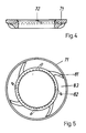
- the cylinder ring 46 is shown viewed from the cylinder block 48.
- the four connecting channels 61 aim radially to the piston axis.
- the connecting channels open into the combustion chamber 52 with sharp edges and rounded off into the adjoining room 50, so that the air jet enters the combustion chamber 52 turbulently and in the opposite direction during combustion the air jet contracts behind the opening, which is associated with Losses.
- the air passage to the combustion chamber 52 is therefore easier, with the reverse braking.
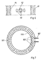
- a cylinder ring 71 is shown in cross section in FIG.
- the connecting channels 72 are inclined at an angle to the axis.
- FIG. 5 shows the cylinder ring 71 from the point of view of the bottom dead center.
- lamellae 81 are attached in a spiral shape running outwards.
- FIG. 6 shows the upper part of the cylinder block 91 in the area of the top dead center of the piston.
- At least one air supply channel 92 opens into the cylinder block 91 and opens into the cylinder wall 94 with at least one nozzle 93.
- Figure 7 shows a cross section in the area of bottom dead center.
- the air supply duct 102 ending in the cylinder block 101 is divided into three air nozzles 103, which are located in the cylinder wall 104. They can be distributed in any number over the entire cross section.
- FIGS. 2 to 7 offer several advantages for four-stroke gasoline engines with indirect gasoline injection or carburetor operation, as well as for diesel engines.
- the stratified charge can be supported by the air supply at the bottom dead center of the piston through the lower air supply channel.
- an air supply duct 30 is provided in the region of the bottom dead center 29 of the piston 12. Through this air supply duct 30, air with a higher pressure than prevailing in the cylinder at this point in time is supplied through at least one opening.
- the suction, and the edge 38 of the piston shoulder 22 crosses the upper edge 39 of the air supply duct air is pressed out of this air into the cylinder until the piston edge begins at the start of the second stroke 38 the piston shoulder 22 again reaches the upper edge 39 of the air supply duct and the air supply ends.
- the opening times depend essentially on the axial height of the piston neck 44, which determines the size of the opening angle 36 as a function of the crank radius of the crankshaft.
- the opening angle 36 is approximately 90 degrees, which corresponds to approximately half of the total suction stroke.
- an additional piston ring 27 can be provided on the lower shaft part of the piston 12.
- the air supply can be brought about by means of a turbocharger or other compressor.
- the air cushions in the adjoining room 24 are preferably fed with pure fresh air from the neck / shoulder area of the piston 12. After ignition and at the point in time when the third stroke of the combustion, the piston edge 38 releases the ring edge, combustion gases flow into the cylinder and mix turn with the spiral-shaped air cushion mixture, swirl intensely and initiate the final combustion.
- the compression chamber no longer contains any combustion gases as in the conventional reciprocating piston engine, but only largely fresh air. This also applies to the air cushions in the adjoining room 24.
- This construction also has the advantage that the hot parts of the piston 42, namely its bottom 43, neck 44 and piston shoulder 22 are additionally cooled.
- a similar effect can be achieved with a second intake valve for pure air, so that a three-valve engine is produced.
- the engine then works as follows: With the first stroke as the intake stroke, the intake valve for pure air opens first. After an opening angle of 10 - 50 degrees, this valve closes again and the inlet valve for mixture opens with an opening angle of 30 - 100 degrees, which means that two layers are sucked into the cylinder, first pure air and then a rich, ignitable mixture. At the second stroke, the rich mixture is predominantly compressed evenly into the combustion chamber and the air cushions in the adjoining room 24 until the piston edge reaches the edge of the cylinder ring.
- the desired fuel-air ratios are set by the ratio of the volumes of the combustion chamber to the adjoining room. The larger the volume of the air cushion in the adjoining room with the same size of the combustion chamber, the more the excess air and lambda increase.
- the stroke volume is 250 ccm
- the volume of the combustion chamber is 17.5 ccm
- the volume of the auxiliary room is 12.4 ccm, so that both together amount to 29.9 ccm.
- the combustion chamber / auxiliary space ratio can be varied within wide ranges.
- the overpressure causes the air cushion to overflow from the adjoining room via the connecting channels and partly also through the gap created by the clearance between the piston neck and the cylinder ring bore.
- the length of the piston neck determines the burning time of the mixture without the inflow of fresh air from the air cushion in the adjoining room.
- the "closing time" is between 0 and 50 degrees crank angle.
- the ratio of the piston neck diameter or the cylinder ring bore to the cylinder diameter should be as large as possible and strive for the value 1 because the combustion chamber is thus largely open
- the diameter ratio is 0.76.
- the diameter ratio is therefore in the range of 1-0.5.
- the piston neck diameter of the stepped piston is advantageous to make up to 50% smaller than the piston diameter.
- the height of the piston neck can be up to about 30% of the total height of the piston.
- several, possibly in the form of a ring, can also be used around the cylinder.
- Several depressions can also be provided in the piston shoulder.
Abstract
Description
Die Erfindung bezieht sich auf einen Verbrennungsmotor, vorzugsweise Viertaktmotor, mit mindestens einem Zylinder, je einem stufenförmig ausgebildeten Kolben, der in eine Durchmesserreduktion des Zylinders einläuft und einem Verfahren zum Betrieb dieses Motores.The invention relates to an internal combustion engine, preferably a four-stroke engine, with at least one cylinder, each with a step-shaped piston that runs into a reduction in the diameter of the cylinder, and a method for operating this engine.
Die Reduzierung von Schadstoffemissionen bei Verbrennungsmotoren ist derzeit ein noch immer anstehendes Problem und wird international mit großem Nachdruck betrieben. Die zulässigen Schadstoffemissionen sind in den meisten Industrieländern durch Verordnungen gesetzlich geregelt.The reduction of pollutant emissions from internal combustion engines is currently still a problem and is being pursued internationally with great emphasis. The permissible pollutant emissions are regulated by law in most industrialized countries.
Nach dem Stand der Technik führt die Nachbehandlung der Abgase von Ottomotoren mittels Katalysator und Lambdasonde zu den niedrigsten Schadstoffmengen.According to the state of the art, the aftertreatment of the exhaust gases from gasoline engines using a catalytic converter and lambda sensor leads to the lowest pollutant quantities.
Hierbei ist Voraussetzung, daß der Motor bei stöchiometrischem Kraftstoff - Luft - Verhältnis (λ = 1) betrieben werden muß.The prerequisite for this is that the engine must be operated with a stoichiometric air / fuel ratio (λ = 1).
Der Nachteil dieses Verfahrens liegt in dem hohen technischen Aufwand für Katalysator und Lambdasonde, dem bis zu 10% höheren Benzinverbrauch, dem vollen Schadstoffausstoß beim Kaltbetrieb, sowie der Wartung und dem Ersatz des Katalysators mit dem Problem der Abfallbeseitigung.The disadvantages of this process are the high technical outlay for the catalytic converter and lambda sensor, the up to 10% higher gasoline consumption, the full emission of pollutants during cold operation, and the maintenance and replacement of the catalytic converter with the problem of waste disposal.
Außer Katalysatoren zur Schadstoffreduzierung sind weitere Versuche unternommen worden, Viertakt-Ottomotoren so zu betrieben, daß eine Säuberung der Abgase mit verringertem Stickoxydgehalt erzielt wird. Dazu zählen einerseits Zündverzögerungen, um die Druckspitze und Temperaturspitze im Verbrennungshub herabzusetzen, sowie dem Einsatz einer Zylinder-Kolben-Einheit gem. der DE-OS 25 09 628, die im wesentlichen Stufenkolben verschiedener Bauart aufweist, die beim Abwärtshub den Verbrennungsraum in zwei Teilräume unterteilen, von denen jeder der Teilräume mit einer Zündkerze ausgerüstet ist und wie ein normaler Brennraum, jedoch mit zeitlich unterschiedlichen Zündzeitpunkten arbeitet.In addition to catalysts for reducing pollutants, further attempts have been made to operate four-stroke gasoline engines in such a way that the exhaust gases are cleaned with a reduced nitrogen oxide content. These include ignition delays to reduce the pressure peak and temperature peak in the combustion stroke, and the use of a cylinder-piston unit according to DE-OS 25 09 628, which essentially has stepped pistons of various types, which divide the combustion chamber into two subspaces during the downward stroke, each of which is equipped with a spark plug and works like a normal combustion chamber, but with different ignition times.
Dadurch allein ändern sich indessen nicht die Druck- und Temperaturspitzen, bzw. tritt die beabsichtigte Minderung der Schadstoffemission, speziell der Stickoxyde nicht ein.However, this alone does not change the pressure and temperature peaks, or the intended reduction in pollutant emissions, especially nitrogen oxides, does not occur.
Entscheidend ist vielmehr das Gemisch/Luftverhältnis und deren optimale Verwirbelung vor und möglichst auch während der Verbrennung.The decisive factor is rather the mixture / air ratio and its optimal turbulence before and if possible also during the combustion.
Dies aber ist mit dem Vorschlag gem. dieser DE-OS nicht möglich.But this is in accordance with the proposal. this DE-OS is not possible.
Die DE-OS 33 27 948 betrifft einen Kolben mit bekannten schrägen Kolbenböden, in diesem Fall mit keil-, bzw. trapezförmiger Gestalt. Damit wird der Verdichtungskammer eine gewünschte Form gegeben. Aber auch eine solche Anordnung ist nicht geeignet, die Schadstoffentstehung zu beeinflussen.DE-OS 33 27 948 relates to a piston with known oblique piston heads, in this case with a wedge or trapezoidal shape. This gives the compression chamber a desired shape. However, even such an arrangement is not suitable for influencing the generation of pollutants.
Der Erfindung liegt daher die Aufgabe zugrunde, einen Verbrennungsmotor zu besitzen, bei dem der Verbrennungsprozeß innerhalb des Zylinders, und zwar sowohl beim Otto-, als auch beim Dieselmotor so abläuft, daß bei möglichst geringem Kraftstoffverbrauch minimale Schadstoffmengen entstehen und dadurch spätere Nachbehandlungen, beispielsweise mittels Katalysator, ganz oder weitgehend überflüssig werden.The invention is therefore based on the object of owning an internal combustion engine in which the combustion process within the cylinder, both in the Otto and in the diesel engine, takes place in such a way that minimal amounts of pollutants are produced with the lowest possible fuel consumption and consequently subsequent treatments, for example by means of Catalyst, completely or largely become superfluous.
Erfindungsgemäß wird dies dadurch erreicht, daß im Bereich des oberen Totpunktes des Kolbens der Durchmesser des Zylinders reduziert ist und der Kolbenhals in diesem Zylinderteil mit geringem Spiel läuft, ein ringförmiger, den Zylinder umgebenden Nebenraum zur Aufnahme eines Luftpolsters vorgesehen ist, der Verbrennungsraum und der Nebenraum zum Zylinder offen und nur im Bereich des oberen Totpunktes voneinander getrennt sind und lediglich durch den Spalt zwischen Kolbenhals und dem Zylinderring miteinander in Verbindung bleiben.According to the invention, this is achieved in that the diameter of the cylinder is reduced in the region of the top dead center of the piston and the piston neck runs with little play in this cylinder part, an annular side space surrounding the cylinder is provided for receiving an air cushion, the combustion space and the side space open to the cylinder and separated from each other only in the area of top dead center and only remain connected to one another through the gap between the piston neck and the cylinder ring.
Vorteilhafterweise ist der Zylinderring als getrenntes Bauteil unterhalb des Zylinderkopfes vorgesehen.The cylinder ring is advantageously provided as a separate component below the cylinder head.
Vorteilhafterweise ist der Nebenraum mit dem Verbrennungsraum über mindestens einen Kanal verbunden.The secondary room is advantageously connected to the combustion chamber via at least one channel.
Vorteilhafterweise ist der Zylinderring Teil des Zylinderkopfes.The cylinder ring is advantageously part of the cylinder head.
Vorteilhafterweise ist der Zylinderring Teil des Zylinderblockes.The cylinder ring is advantageously part of the cylinder block.
Vorteilhafterweise ist der Kolbenboden eben ausgebildet.The piston crown is advantageously flat.
Vorteilhafterweise ist der Kolbenboden konkav oder konvex geformt.The piston crown is advantageously of concave or convex shape.
Vorteilhafterweise weist der Zylinderring mindestens einen spiralförmigen Flügel gegenüber dem Verbrennungsraum auf.The cylinder ring advantageously has at least one spiral wing opposite the combustion chamber.
Vorteilhafterweise beträgt die Höhe des Kolbenhalses bis zu etwa 30% der Gesamthöhe des Kolbens.The height of the piston neck is advantageously up to approximately 30% of the total height of the piston.
Vorteilhafterweise ist der Zylinderblock von einem Luftzuführungskanal durchdrungen, der in der Zylinderwand in der Nähe des unteren Totpunktes des Kolbens mündet.The cylinder block is advantageously penetrated by an air supply channel which opens into the cylinder wall in the vicinity of the bottom dead center of the piston.
Vorteilhafterweise mündet der Luftzuführungskanal über Düsen in der Zylinderwand.The air supply duct advantageously opens out via nozzles in the cylinder wall.
Vorteilhafterweise ist der Zylinderblock von einem Luftzuführungskanal durchdrungen, der in der Nähe des oberen Totpunktes des Kolbens mündet.Advantageously, the cylinder block is penetrated by an air supply channel which opens near the top dead center of the piston.
Vorteilhafterweise ist im Kolbenhals mindestens eine Mulde vorgesehen.At least one trough is advantageously provided in the piston neck.
Vorteilhafterweise ist in der Kolbenschulter mindestens eine Vertiefung vorgesehen.At least one depression is advantageously provided in the piston shoulder.
Vorteilhafterweise verläuft der Verbindungskanal geradlinig.The connecting channel advantageously runs in a straight line.
Vorteilhafterweise verläuft der Verbindungskanal spiralförmig.The connecting channel advantageously runs in a spiral.
Vorteilhafterweise besteht der Zylinderring aus keramischem Werkstoff.The cylinder ring is advantageously made of ceramic material.
Vorteilhafterweise ist der Zylinderring mit keramischem Werkstoff beschichtet.The cylinder ring is advantageously coated with ceramic material.
Vorteilhafterweise sind mehrere Zylinderringe als Einlegeteil zusammengefaßt.Advantageously, several cylinder rings are combined as an insert.
Vorteilhafterweise ist/sind der/die Zylinderring(e) in den Zylinderkopf integriert. Das Verfahren zum Betrieb des Verbrennungsmotores zeichnet sich erfindungsgemäß dadurch aus, daß man den Kompressionsraum des Zylinders in einen Raum mit zündfähigem Gemisch von lambda = 0,6-1,0, welches zunächst gezündet wird und einen weiteren Raum, einen Luftpolsterraum, gefüllt mit Luft, bzw. magerem Gemisch unterteilt, die bzw.das kurz vor Abschluß der Kompression, infolge des Überdruckes in den Luftpolstern teilweise in den Brennraum über Kanäle und einen Spalt stark wirbelnd einblasen und nach der Zündung, sobald der Kolbenboden die untere Kante des Zylinderringes überschreitet, stark wirbelnd in die brennenden Gase des Zylinders einströmen läßt, um mit hohem Luftüberschuß die weitere Verbrennung zu fördern, wobei zusätzlich noch über ein Luftzuführungsrohr im Bereich des unteren Totpunktes des Kolbens Frischluft in den Bereich des Kolbenhalses und der Kolbenschulter eingeblasen werden kann,umeinen Schichtladeeffekt zu erzielen.The cylinder ring (s) is / are advantageously integrated into the cylinder head. The method for operating the internal combustion engine is characterized according to the invention in that the compression space of the cylinder is in a space with an ignitable mixture of lambda = 0.6-1.0, which is initially ignited, and another space, an air cushion space filled with air , or lean mixture, which or shortly before the end of the compression, due to the overpressure in the air cushions, partially blowing into the combustion chamber via ducts and a gap, and after ignition, as soon as the piston crown exceeds the lower edge of the cylinder ring, flows in a swirling manner into the burning gases of the cylinder in order to promote further combustion with a large excess of air, whereby fresh air can also be blown into the region of the piston neck and the piston shoulder via an air supply pipe in the region of the bottom dead center of the piston in order to create a stratified charging effect achieve.
Im Gegensatz zu DE-OS 24 02 507 wird erfindungsgemäß der Brennraum nicht in zwei Brennräume getrennt, es bleibt vielmehr stets ein Brennraum und ein Luftpolster erhalten, die im Takt der Kolbenbewegung getrennt bzw. zugeschaltet werden, wobei es je nach dem Verhältnis von Bohrungen des Zylinderringes im Zylinder auf die Abstufung des Kolbens ankommt. Wenn der Kolbenhals sich dem Durchmesser des Zylinders nähert, rücken die Luftpolster aus dem Bereich des Zylinders entweder ganz in den Zylinderkopf oder Zylinderblock.In contrast to
Dann entsteht aber im Luftpolster kein Überdruck mehr, der zum Überströmen notwendig ist. Auch ist das Gemischverhältnis im Brennraum und Luftpolster gleich, was nicht gewollt ist.Then, however, there is no longer any excess pressure in the air cushion that is necessary for overflow. The mixture ratio in the combustion chamber and air cushion is the same, which is not wanted.
Diese Luftpolster können aus mindestens einem nicht unterteiltem Raum oder aus mehreren unterschiedlich großen und geformten Räumen bestehen.These air cushions can consist of at least one non-subdivided room or of several differently sized and shaped rooms.
Der mit der Erfindung erzielte Vorteil liegt insbesondere in folgendem:The advantage achieved with the invention lies in particular in the following:
Bekanntlich kann der Verbrennungsprozeß mit Luftüberschuß von etwa 50% einerseits das Entstehen von Stickoxyden weitgehend verhindern und andererseits den Kraftstoffverbrauch reduzieren. Ein Nachteil dieser auch als Magermotoren bezeichneten Motoren ist, daß die Fahrtauglichkeit unbefriedigend ist, weil mit zunehmendem Luftüberschuß die Zündwilligkeit abnimmt und schließlich die Zündfähigkeit überhaupt aufhört. Aus diesem Grunde ist es notwendig, im Bereich der durch die Zündkerze ausgelösten Verbrennung ein noch sicher zündfähiges Gemisch anzubieten, das nur vorzugsweise bei annähernd λ = 1 liegt und nach erfolgter Zündung soviel Luft und/oder mageres allein nicht mehr zündfähiges Gemisch zugeführt wird, daß für den gesamten Brennraum der hohe gewünschte Luftüberschuß erreicht wird, was mit dem erfindungsgemäß vorgeschlagenen Verbrennungsmotor gelungen ist. Sobald nämlich der Kolbenboden die untere Kante des Zylinderringes überschreitet, strömt aus dem Luftpolster stark wirbelnd Luft und/oder mageres Gemisch in die brennenden Gase des Zylinders und fördert dadurch auch mit hohem Luftüberschuß die weitere Verbrennung.As is known, the combustion process with an excess of air of about 50% on the one hand largely prevents the formation of nitrogen oxides and on the other hand reduces fuel consumption. A disadvantage of these engines, which are also referred to as lean-burn engines, is that the suitability for driving is unsatisfactory, because with increasing air excess the ignitability decreases and finally the ignitability ceases. For this reason, it is necessary to offer a still ignitable mixture in the area of the combustion triggered by the spark plug, which is only preferably at approximately λ = 1 and, after ignition, so much air and / or lean mixture that is no longer ignitable is supplied that the high desired excess air is achieved for the entire combustion chamber, which has been achieved with the internal combustion engine proposed according to the invention. As soon as the piston crown exceeds the lower edge of the cylinder ring, air and / or a lean mixture flows out of the air cushion into the burning gases of the cylinder and thus promotes further combustion even with a high excess of air.
In den letzten Jahrzehnten sind auf dem Gebiet der optimalen Verbrennung sowohl beim Otto- als auch Dieselmotor durch bauliche Maßnahmen hauptsächlich im Bereich der Zylinderköpfe und Kolben bedeutende Verbesserungen erzielt worden, beispielsweise durch die Direkteinpritzung oder die Einführung einer Vorkammer, die mit dem Arbeitszylinder durch mindestens eine Öffnung verbunden ist. Beim Wirbelkammerverfahren wird bekanntlich der Kraftstoff auch erst in eine Kammer gespritzt, die wiederum durch eine relativ weite Öffnung mit dem Arbeitszylinder verbunden ist. Auch eine besondere Ausbildung des Kolbenbodens mit beispielsweise kugelförmigemBrennraum dient derselben Zielsetzung.In recent decades, significant improvements have been achieved in the field of optimal combustion for both gasoline and diesel engines through structural measures, mainly in the area of the cylinder heads and pistons, for example through direct injection or the introduction of a prechamber that can be connected to the working cylinder by at least one Opening is connected. In the swirl chamber method, it is known that the fuel is first injected into a chamber, which in turn is connected to the working cylinder through a relatively wide opening. A special design of the piston crown, for example with a spherical combustion chamber, also serves the same purpose.
Die bekannten Maßnahmen reichen insbesondere für den Vergaserbetrieb nicht aus. Zur Reduzierung der Schadstoffemissionen wurden ferner zahlreiche Verfahren entwickelt; u.a. sie die Abmagerung des Gemisches, eine intensive Ladungsbewegung und Schichtladung, oder sequente Zündung genannt.The known measures are not sufficient, in particular for gasifier operation. Numerous processes have also been developed to reduce pollutant emissions; among other things, they called the emaciation of the mixture, an intensive charge movement and stratified charge, or sequential ignition.
Somit sind chemische/physikalische Nachbehandlungen der giftstoffbelasteten Abgase weitgehend vermieden,das heißt überflüssig, weil die Giftstoffe wegen der Steuerung des Verbrennungsablaufes nicht erst entstehen können.This means that chemical / physical aftertreatments of the exhaust gases contaminated with toxic substances are largely avoided, that is to say superfluous, because the toxins cannot be created due to the control of the combustion process.
Die Erfindung ist nachstehend anhand der in den Abbildungen dargestellten Ausführungsbei spiele näher erläutert.The invention is explained below with reference to the game Ausführungsbei shown in the figures.
Es zeigt:
- Figur 1 einen Teilschnitt durch einen Zylinder,
- Figur 2 eine Ausführungsvariante der Figur 1,
- Figur 3 eine Draufsicht auf einen Zylinderring,
- Figur 4 einen Schnitt durch eine Ausführungsvariante der Figur 3, und
- Figur 5 eine Draufsicht auf Figur 4.
- Figur 6 den Längsschnitt durch einen Zylinder gem. Figur 1, und
- Figur 7 einen Querschnitt durch die Figur 6.
- FIG. 1 shows a partial section through a cylinder,
- FIG. 2 shows an embodiment variant of FIG. 1,
- FIG. 3 shows a top view of a cylinder ring,
- Figure 4 shows a section through an embodiment of Figure 3, and
- FIG. 5 is a top view of FIG. 4.
- 6 shows the longitudinal section through a cylinder acc. Figure 1, and
- FIG. 7 shows a cross section through FIG. 6.
In Figur 1 ist ein erstes Ausführungsbeispiel des Zylinders 11 eines Verbrennungsmotors dargestellt. In dem Zylinder 11 befindet sich der Kolben 12 in der oberen Totpunktstellung. Der Zylinderkopf 13, mit den nicht dargestellten Ventilen in dem Einlaßkanal 14 und Auslaßkanal 15 schließt den Zylinder 11 dichtend ab und bildenso den Verbrennungsraum 16, der vom Zylinderkopf 13, dem Kolbenboden 17 und einem Zylinderring 18 umhüllt wird.In Figure 1, a first embodiment of the
Die Bohrung 23 des Zylinderringes 18 ist mittels der Kante 19 zur Bohrung 20 des Zylinders 11 zentriert. Der Kolben 12 ist als Stufenkolben mit dem zylindrierten Kolbenhals 21 und der Kolbenschulter 22 ausgebildet. Der Kolbenhals 21 ragt in dieser Totpunktstellung mit geringstem Spiel in die Bohrung 23 des Zylinderringes 18. Der das Luftpolster aufnehmende Nebenraum 24 wird durch die Kolbenschulter 22, die Innenseite 25 des Zylinderringes 18 und der Wandfläche 26 des Zylinderkopfes 13 gebildet.The
Über den Dichtungs- bzw. Ölabstreifringen 27 ist wie üblich der Feuersteg 28 angeordnet.Ein Luftzuführungsrohr 30 ist im Bereich des unteren Totpunktes vorgesehen.Ein weiteres Luftzuführungsrohr kann ggf.auch zusätzlich am oberen Totpunkt vorgesehen sein.As usual, the
Im folgenden sind die Arbeitsweisen der verschiedenen Motortypen mit direkter und indirekter Einspritzung sowie Vergaserbetrieb beschrieben. Zunächst als Beispiel ein konventioneller Viertakt-Ottomotor mit direkter Benzineinspritzung.The working methods of the various engine types with direct and indirect injection and carburetor operation are described below. First, as an example, a conventional four-stroke gasoline engine with direct petrol injection.
In Figur 1 befindet sich der Kolben 12 nach dem Ausstoßen der verbrannten Gase in der oberen Totpunktstellung. Das Auslaßventil im Auslaßkanal 15 ist geschlossen und das Einlaßventil im Einlaßkanal 14 offen. Mit dem ersten Hub des Kolbens beginnt das Ansaugen der Luft, mit dem zweiten Hub die Kompression dieser Luft und im Verlauf dieser Kompression die Benzineinspritzung durch die Düse 32 in der Weise, daß im Kompressionsraum die Hauptmenge des Kraftstoffes verbleibt und zu einem gut zündbaren Gemisch komprimiert wird.In Figure 1, the
Die Luftpolster im Nebenraum 24 werden dagegen vorwiegend mit der vorkomprimierten Luft bzw. mit schwach angereichertem Benzinluftgemisch gefüllt. Der dritte Hub beginnt mit der Zündung durch die Zündkerze 33. Nachdem der Kolben soweit in Richtung unterer Totpunkt gewandert ist, daß die Kante des Kolbenbodens 34 die untere Kante 35 des Zylinderringes verläßt, strömen die heißen Verbrennungsgase in den Zylinder 11. Gleichzeitig oder kurzfristig danach strömt die komprimierte Luft bzw. das schwach angereicherte Luftbenzingemisch spiralförmig von den Flügeln 81 geleitet in die Verbrennungsgase und verwirbeln dort mit ihnen und vollenden somit den Verbrennungsprozeß mit großem Luftüberschuß.The air cushions in the adjoining
Mit Beginn des vierten Hubes erfolgt das Ausstossen der verbrannten Gase durch den Auslaßkanal 15.At the beginning of the fourth stroke, the burned gases are expelled through the
In dem Zeitpunkt, in dem die Kante 34 des Kolbens 12 die Kante 35 des Zylinderringes 18 erreicht, wird der Verbrennungsraum 16 im wesentlichen geschlossen, wobei die verbrannten Gase des Verbrennungsraumes 16 weiter ausgestossen werden,die Verbrennungsgase im Nebenrum 24 werden leicht komprimiert.At the point in time at which the
Nunmehr beginnt das Viertaktspiel von neuem. Sobald, wie bereits oben beschrieben, die Kante 34 des Kolbens 12 die Kante 35 des Zylinderringes 18 wieder erreicht und den Zylinderraum öffnet, strömt der unter leichtem Überdruck stehende Inhalt des Nebenraumes 24 in den Zylinder, sodaß beim zweiten Hub der Nebenraum 24 wieder mit weitgehend frischer Luft bzw. schwach angereicherter Luft gefüllt werden kann.Now the four-stroke game starts again. As soon as, as already described above, the
Mit diesem Verfahren läßt sich also Schichtladung und Magermotorbetrieb optimal verwirklichen.With this method, stratified charge and lean engine operation can be optimally implemented.
In Figur 2 ist ein weiteres Ausführungsbeispiel dargestellt. In diesem Fall bleibt der Zylinderkopf 41 ohne angegossenen Zylinderring, d.h. also in der konventionellen Bauweise. Der Zylinderring 46 wird als neues Bauteil zentrisch zur Zylinderringbohrung 49 durch die Zylinderringzentrierung 47 in den Zylinderblock 48 dichtend eingesetzt. In dem Zylinderring 46 ist mindes tens ein Verbindungskanal 51 angebracht, der den Nebenraum (das Luftpolster) 50 mit dem Brennraum 52 verbindet. Der Kolbenboden 43 ist konkav gewölbt.Another exemplary embodiment is shown in FIG. In this case, the
Der Nebenraum 50 mit dem Luftpolster wird von dem Zylinderring 46, der Wölbung 53 des Zylinderblockes 48 und der Kolbenschulter 45 gebildet.The
Mit 56 ist mindestens eine Mulde am unteren Ende des Kolbenhalses 44 bezeichnet.At least one depression at the lower end of the
In Figur 3 ist der Zylinderring 46 vom Zylinderblock 48 aus gesehen dargestellt. Die vier Verbindungskanäle 61 zielen radial zur Kolbenachse.Die Verbindungskanäle münden in den Brennraum 52 scharfkantig und in den Nebenraum 50 abgerundet, sodaß der Luftstrahl turbulent in den Brennraum 52 tritt und in umgekehrter Richtung während der Verbrennung sich der Luftstrahl hinter der Öffnung zusammenzieht, was mit Verlusten verbunden ist. Der Luftdurchgang zum Brennraum 52 erfolgt also leichter, umgekehrt gebremster.In Figure 3, the
In Figur 4 ist ein Zylinderring 71 im Querschnitt dargestellt. Die Verbindungskanäle 72 sind winkelig zur Achse geneigt.A
Figur 5 stellt den Zylinderring 71 aus der Sicht des unteren Totpunktes dar. In dem Luftpolster 83 sind Lamellen 81 spiralförmig nach außen verlaufend angebracht.FIG. 5 shows the
Infolge dieser Ausbildung tritt die Luft aus dem Nebenraum 83 mit einem zu Kolbenboden und Kolbenschulter geneigten Drall in den Zylinder und verwirbelt dadurch das brennende Gemisch intensiv.As a result of this design, the air from the adjoining
Figur 6 zeigt den oberen Teil des Zylinderblockes 91 im Bereich des oberen Totpunktes des Kolbens. In den Zylinderblock 91 mündet mindestens ein Luftzuführungskanal 92, der mit mindetens einer Düse 93 in der Zylinderwand 94 mündet.FIG. 6 shows the upper part of the
Figur 7 zeigt einen Querschnitt im Bereich des unteren Totpunktes. Der im Zylinderblock 101 endende Luftzuführungskanal 102 teilt sich in diesem Falle in drei Luftdüsen 103, die in der Zylinderwand 104 liegen.Sie können über den gesamten Querschnitt in beliebiger Zahl verteilt sein.Figure 7 shows a cross section in the area of bottom dead center. In this case, the
Die in Figur 2 bis 7 wiedergegebenen Details bieten erfindungsgemäß mehrere Vorteile für Viertakt-Ottomotoren mit indirekter Benzineinspritzung oder Vergaserbetrieb, wie auch für Dieselmotoren.According to the invention, the details shown in FIGS. 2 to 7 offer several advantages for four-stroke gasoline engines with indirect gasoline injection or carburetor operation, as well as for diesel engines.
Beim Viertakt-Ottomotor mit indirekter Benzineinspritzung ist die Arbeitsfolge gleich wie beim beschriebenen Motor mit direkter Einspritzung mit der Abweichung, daß die Benzineinspritzung früher als bei der direkten Einspritzung erfolgt mit dem Effekt, daß die Übergangszone zwischen Luft und Gemisch stärker vermischt und die Schichtbildung nicht so ausgeprägt ist.In the four-stroke gasoline engine with indirect gasoline injection, the sequence of operations is the same as in the engine with direct injection described, with the difference that the gasoline injection takes place earlier than in the direct injection with the effect that the transition zone between air and mixture is stronger mixed and the layer formation is not so pronounced.
Unterstützt werden kann die Schichtladung durch die Luftzufuhr im unteren Totpunkt des Kolbens durch den unteren Luftzuführungskanal.The stratified charge can be supported by the air supply at the bottom dead center of the piston through the lower air supply channel.
Nachstehend wird die Arbeitsweise und Wirkung des erfindungsgemäss ausgebildeten Motors anhand eines Viertakt-Ottomotors mit Vergaserbetrieb beschrieben.The mode of operation and effect of the engine designed according to the invention is described below using a four-stroke gasoline engine with carburetor operation.
Bei Viertaktmotoren mit Vergaserbetrieb bedarf es einer zusätzlichen Einrichtung, weil Schichtladung und und Füllung des Nebenraumes 24 (Luftpolster) mit Luft und/oder magerem Gemisch nicht möglich ist.In the case of four-stroke engines with carburetor operation, additional equipment is required because stratified charge and and filling of the adjoining room 24 (air cushion) with air and / or a lean mixture is not possible.
Für diesen Fall ist erfindungsgemäß ein Luftzuführungskanal 30 im Bereich des unteren Totpunktes 29 des Kolbens 12 vorgesehen.Durch diesen Luftzuführungskanal 30 wird Luft mit höherem als in diesem Zeitpunkt im Zylinder herrschenden Druck durch mindestens eine Öffnung zugeführt.For this case, according to the invention, an
Sobald der Kolben 12 beim ersten Takt, dem Ansaugen, sich dem unteren Totpunkt 29 nähert und die Kante 38 der Kolbenschulter 22 den oberen Rand 39 des Luftzuführungskanales überschreitet, wird aus diesem Luft solange in den Zylinder gedrückt, bis zu Beginn des zweiten Taktes die Kolbenkante 38 der Kolbenschulter 22 wieder den oberen Rand 39 des Luftzuführungskanales erreicht und die Luftzufuhr beendet. Die Öffungszeiten richten sich im wesentlichen nach der axialen Höhe des Kolbenhalses 44, die die Größe des Öffnungswinkels 36 in Abhängigkeit vom Kurbelradius der Kurbelwelle bestimmt.As soon as the
In dem in Fig.1 dargestellten Beispiel eines Kolbendurchmessers von 7o mm und eines Kolbenhubes von 57 mm beträgt der Öffnungswinkel 36 ca 90 Grad, was etwa der Hälfte des gesamten Ansaughubes entspricht.In the example of a piston diameter of 70 mm and a piston stroke of 57 mm shown in FIG. 1, the
Zur Verringerung etwaiger Luftverluste in die Kurbelwanne kann am unteren Schaftteil des Kolbens 12 ein zusätzlicher Kolbenring 27 vorgesehen sein.To reduce any air loss in the crankcase, an
Die Luftzufuhr kann mittels eines Turboladers oder sonstigen Verdichters herbeigeführt werden.The air supply can be brought about by means of a turbocharger or other compressor.
Um und über dem Kolbenboden 17 und dem Bereich des Kolbenhalses21 und der Kolbenschulter 22 liegt der Bereich reiner Luft oder eines äusserst mageren Gemisches, sodaß bei Vollendung der Kompression im Kompressionsraum in der Nähe der Zündkerze 33 ein fettes Gemisch liegt, das zum Kolbenboden hin immer magerer wird.Around and above the piston crown 17 and the area of the
Die Luftpolster im Nebenraum 24 sind vorzugsweise mit reiner Frischluft aus dem Hals/Schulter Bereich des Kolbens 12 gespeist worden. Nach der Zündung und in dem Zeitpunkt in dem beim dritten Takt der Verbrennung, die Kolbenkante 38 die Ringkante freigibt, strömen Verbrennungsgase in den Zylinder und vermischen sich wiederum mit dem spiralförmig austretenden Luftpolstergemisch, verwirbeln intensiv und leiten die endgültige Verbrennung ein.The air cushions in the adjoining
Am Ende dieses Verbrennungstaktes, wenn die Kolbenkante den oberen Rand des Zuführungsrohres erreicht, beginnt wieder das Zuströmen der Luft, sodaß der untere Zylinderteil von Verbrennungsgasen freigespült wird.At the end of this combustion cycle, when the piston edge reaches the upper edge of the feed pipe, the air begins to flow again, so that the lower cylinder part is flushed away by combustion gases.
Dies hat zufolge, daß am Ende des vierten Taktes, dem Auspuff, der Kompressionsraum keine Verbrennungsgase mehr wie beim konventionellen Hubkolbenmotor enthält, sondern nur noch weitgehend Frischluft.Dies trifft ebenfalls für die Luftpolster im Nebenraum 24 zu.Diese Bauweise hat überdies den Vorteil, daß die heißen Partien des Kolbens 42, nämlich dessen Boden 43, Hals 44 und Kolbenschulter 22 zusätzlich gekühlt werden.As a result, at the end of the fourth stroke, the exhaust, the compression chamber no longer contains any combustion gases as in the conventional reciprocating piston engine, but only largely fresh air. This also applies to the air cushions in the adjoining
Ein ähnlicher Effekt kann mit einem zweiten Einlaßventil für reine Luft erreicht werden, sodaß ein Dreiventil-Motor entsteht.A similar effect can be achieved with a second intake valve for pure air, so that a three-valve engine is produced.
Die Arbeitsweise des Motors ist dann wie folgt:Beim ersten Takt als Ansaugtakt öffnet zuerst das Einlaßventil für reine Luft. Nach einem Öffnungswinkel von 10 - 50 Grad schließt dieses Ventil wieder und das Einlaßventil für Gemisch öffnet mit einem Öffnungswinkel 30 - 100 Grad.Dadurch werden in dem Zylinder zwei Schichten angesaugt, nämlich zuerst reine Luft und anschließend fettes, zündfähiges Gemisch. Beim zweiten Takt wird das fette Gemisch vorwiegend in den Brennraum und die Luftpolster im Nebenraum 24 gleichmässig komprimiert, bis die Kolbenkante die Kante des Zylinderringes erreicht. Von diesem Augenblick an steigt der Druck in dem Nebenraum d.h. dem Luftpolster stärker als im Brennraum, sodaß das Gemisch in der Nähe der Verbindungskanäle 51 in den Brennraum strömt und die reine Luft mit Resten des Gemisches in dem Nebenraum 50 verbleibt.Dann verläuft der dritte und vierte Takt wie bereits oben beschrieben,d.h. beim Verbrennungstakt wird durch den Überdruck im Verbrennungsraum heißes Gas in den bzw. die Nebenräume 50 dringen, sodaß die Luft stark wirbelnd in die brennenden Gase strömt,wenn der Kolben 42 den Verbrennungsraum 52 und Zylinder öffnet.The engine then works as follows: With the first stroke as the intake stroke, the intake valve for pure air opens first. After an opening angle of 10 - 50 degrees, this valve closes again and the inlet valve for mixture opens with an opening angle of 30 - 100 degrees, which means that two layers are sucked into the cylinder, first pure air and then a rich, ignitable mixture. At the second stroke, the rich mixture is predominantly compressed evenly into the combustion chamber and the air cushions in the adjoining
Die gewünschten Kraftstoff - Luft - Verhältnisse werden durch das Verhältnis der Volumina des Brennraumes zu Nebenraum eingestellt.Je größer das Volumen des Luftpolsters im Nebenraum bei gleichbleibender Größe des Brennraumes ist,desto mehr steigt der Lufüberschuß und Lambda.The desired fuel-air ratios are set by the ratio of the volumes of the combustion chamber to the adjoining room. The larger the volume of the air cushion in the adjoining room with the same size of the combustion chamber, the more the excess air and lambda increase.
In Fig.1 ist z.B.das Hubvolumen 250 ccm,das Volumen des Brennraumes 17,5 ccm und das Volumen des Nebenraumes 12,4 ccm, sodaß beide zusammen 29,9 ccm betragen. Das Verdichtungsverhältnis berechnet sind demnach zu ε = 9,5.In Fig. 1, for example, the stroke volume is 250 ccm, the volume of the combustion chamber is 17.5 ccm and the volume of the auxiliary room is 12.4 ccm, so that both together amount to 29.9 ccm. The compression ratio is calculated as ε = 9.5.
Durch die Höhe des Kolbenhalses und der Breite der Kolbenschulter läßt sich das Brennraum / Nebenraumverhältnis in weiten Bereichen variieren.Due to the height of the piston neck and the width of the piston shoulder, the combustion chamber / auxiliary space ratio can be varied within wide ranges.
Das Optimum kann für jeden Motor nur durch Versuch erprobt werden.The optimum can only be tried out for each engine by trial.
In der "Schließ - Stellung", d.h.wenn die Kolben kopfkante den Zylinderring erreicht,herrscht ein theoretisch gleicher Druck in beiden Räumen von p =12,2, berechnet nach der Formel p₂=p₁¹ʼ³.In gleicher Weise errechnet herrscht im oberen Totpunkt in dem Nebenraum ein um 5 - 6 bar höherer Druck.Dieser Überdruck kann durch die Kolbenbodenform in weiten Grenzen variiert werden.Ein konvexer Kolbenboden,wie in Fig.2 gezeigt, erhöht bei sonst gleichen Abmessungen diesen Überdruck z.B.auf 9 - 10 bar,umgekehrt wird durch einen konkaven Kolbenboden dieser Überdruck reduziert.In the "closed position", ie when the piston head edge reaches the cylinder ring, there is theoretically the same pressure in both rooms of p = 12.2, calculated according to the formula p₂ = p₁¹ʼ³ Side room has a pressure that is 5 - 6 bar higher. This overpressure can be varied within wide limits due to the shape of the piston crown. A convex piston crown, as shown in Fig a concave piston crown reduces this overpressure.
Durch den Überdruck erfolgt ein Überströmen des Luftpolsters aus dem Nebenraum über die Verbindungskanäle und zum Teil auch über den durch das Spiel zwischen Kolbenhals und Zylinderringbohrung entstehenden Spalt.The overpressure causes the air cushion to overflow from the adjoining room via the connecting channels and partly also through the gap created by the clearance between the piston neck and the cylinder ring bore.
Die Länge des Kolbenhalses bestimmt die Brenndauer des Gemisches ohne Zufluß von Frischluft aus dem Luftpolster des Nebenraumes. Die "Schließzeit" liegt zwischen 0 und 50 Grad Kurbelwinkel.The length of the piston neck determines the burning time of the mixture without the inflow of fresh air from the air cushion in the adjoining room. The "closing time" is between 0 and 50 degrees crank angle.
Das Verhältnis des Kolbenhalsdurchmessers oder der Zylinderringbohrung zum Zylinderdurchmesser soll möglichst groß sein und den Wert 1 anstreben,weil damit der Brennraum weitgehend offen gestaltet wird.Im Beispiel gem. Fig. 1 beträgt der Zylinderdurchmesser 7o mm,der des Kolbenhalses 53 mm,das Durchmesserverhältnis beträgt also o,76.Das Durchmesserverhältnis liegt somit im Bereich von 1 - o,5.The ratio of the piston neck diameter or the cylinder ring bore to the cylinder diameter should be as large as possible and strive for the value 1 because the combustion chamber is thus largely open In the example according to 1 has a cylinder diameter of 7o mm, that of the
Es ist günstig,den Kolbenhalsdurchmesser des Stufenkolbens um bis zu 50 % kleiner als den Kolbendurchmesser vorzusehen.Die Höhe des Kolbenhalses kann bis etwa 30 % der gesamten Höhe des Kolbens betragen.Anstelle eines Nebenraumes für die Aufnahme des Luftpolsters können auch mehrere,möglichst ringförmig um den Zylinder herum, angeordnet sein.In der Kolbenschulter können auch mehrere Mulden vorgesehen werden.It is advantageous to make the piston neck diameter of the stepped piston up to 50% smaller than the piston diameter. The height of the piston neck can be up to about 30% of the total height of the piston. Instead of an adjoining room for accommodating the air cushion, several, possibly in the form of a ring, can also be used around the cylinder. Several depressions can also be provided in the piston shoulder.
Die Erfindung ist selbstverständlich nicht auf die angegebenen Ausführungsbeispiele beschränkt, vielmehr können auch andere Ausführungsformen vorgesehen werden, ohne den Erfindungsgedanken zu verlassen.The invention is of course not limited to the exemplary embodiments specified, rather other embodiments can also be provided without departing from the inventive concept.
Claims (21)
Priority Applications (1)
| Application Number | Priority Date | Filing Date | Title |
|---|---|---|---|
| EP88111476A EP0351438A1 (en) | 1988-07-16 | 1988-07-16 | Internal combustion engine |
Applications Claiming Priority (1)
| Application Number | Priority Date | Filing Date | Title |
|---|---|---|---|
| EP88111476A EP0351438A1 (en) | 1988-07-16 | 1988-07-16 | Internal combustion engine |
Publications (1)
| Publication Number | Publication Date |
|---|---|
| EP0351438A1 true EP0351438A1 (en) | 1990-01-24 |
Family
ID=8199124
Family Applications (1)
| Application Number | Title | Priority Date | Filing Date |
|---|---|---|---|
| EP88111476A Withdrawn EP0351438A1 (en) | 1988-07-16 | 1988-07-16 | Internal combustion engine |
Country Status (1)
| Country | Link |
|---|---|
| EP (1) | EP0351438A1 (en) |
Cited By (6)
| Publication number | Priority date | Publication date | Assignee | Title |
|---|---|---|---|---|
| EP0486963A1 (en) * | 1990-11-22 | 1992-05-27 | Hugo Kueckenwaitz | Combustion engine with a plurality of combustion chambers |
| EP0512697A1 (en) * | 1991-05-03 | 1992-11-11 | Ford Motor Company Limited | Air cell for an internal combustion engine |
| GB2318402A (en) * | 1996-10-17 | 1998-04-22 | T & N Technology Ltd | Piston with cavity |
| GB2319297A (en) * | 1996-11-14 | 1998-05-20 | T & N Technology Ltd | I.c. engine piston with chambers for sheltering radical fuel species |
| EP1757783A1 (en) * | 2005-08-27 | 2007-02-28 | DEUTZ Aktiengesellschaft | Water cooled combustion engine |
| GR20080100240A (en) * | 2008-04-09 | 2009-11-19 | Διονυσιος Χαραλαμπους Χοϊδας | Protection method of the flange of the head of a reciprocating internal combustion engine. |
Citations (1)
| Publication number | Priority date | Publication date | Assignee | Title |
|---|---|---|---|---|
| DE8703130U1 (en) * | 1987-02-28 | 1987-07-02 | Koepke, Guenter, Dr.-Ing., 8183 Rottach-Egern, De |
-
1988
- 1988-07-16 EP EP88111476A patent/EP0351438A1/en not_active Withdrawn
Patent Citations (1)
| Publication number | Priority date | Publication date | Assignee | Title |
|---|---|---|---|---|
| DE8703130U1 (en) * | 1987-02-28 | 1987-07-02 | Koepke, Guenter, Dr.-Ing., 8183 Rottach-Egern, De |
Cited By (7)
| Publication number | Priority date | Publication date | Assignee | Title |
|---|---|---|---|---|
| EP0486963A1 (en) * | 1990-11-22 | 1992-05-27 | Hugo Kueckenwaitz | Combustion engine with a plurality of combustion chambers |
| EP0512697A1 (en) * | 1991-05-03 | 1992-11-11 | Ford Motor Company Limited | Air cell for an internal combustion engine |
| GB2318402A (en) * | 1996-10-17 | 1998-04-22 | T & N Technology Ltd | Piston with cavity |
| GB2319297A (en) * | 1996-11-14 | 1998-05-20 | T & N Technology Ltd | I.c. engine piston with chambers for sheltering radical fuel species |
| GB2319297B (en) * | 1996-11-14 | 2000-04-12 | T & N Technology Ltd | Piston with chamber |
| EP1757783A1 (en) * | 2005-08-27 | 2007-02-28 | DEUTZ Aktiengesellschaft | Water cooled combustion engine |
| GR20080100240A (en) * | 2008-04-09 | 2009-11-19 | Διονυσιος Χαραλαμπους Χοϊδας | Protection method of the flange of the head of a reciprocating internal combustion engine. |
Similar Documents
| Publication | Publication Date | Title |
|---|---|---|
| AT402322B (en) | HYBRID COMBUSTION PISTON ENGINE | |
| DE2711681C2 (en) | Spark ignition internal combustion engine | |
| DE60201494T2 (en) | Combustion chamber for spark-ignition engine with direct injection and vertical swirl | |
| DE19643886C2 (en) | Method for operating an internal combustion engine | |
| DE69533226T2 (en) | TWIN PISTON internal combustion engine | |
| DE3516951A1 (en) | HYBRID COMBUSTION PISTON ENGINE | |
| DE3248918T1 (en) | COMBUSTION ENGINE WITH EXHAUST GAS RECIRCULATION AND METHOD FOR OPERATING THE SAME | |
| DE4441092A1 (en) | Valve for the introduction of fuel or fuel-air mixture | |
| DE2523712A1 (en) | DOUBLE PISTON TWO-STROKE COMBUSTION ENGINE | |
| DE3143402A1 (en) | Two-stroke internal combustion engine | |
| EP0351438A1 (en) | Internal combustion engine | |
| EP0829636B1 (en) | Internal combustion engine | |
| DE3706592C2 (en) | ||
| DE2915514A1 (en) | INTERNAL IGNITION ENGINE AND GASOLINE INJECTION | |
| DE3226960A1 (en) | PISTON COMBUSTION ENGINE | |
| DE2114901A1 (en) | Internal combustion engine with air storage space and fuel injection | |
| DE2542942A1 (en) | Internal combustion engine with spark ignition - has turbulence chamber under exhaust valve in cylinder head and containing spark plug | |
| EP0345436A1 (en) | Two-stroke double piston engine | |
| DE2745902A1 (en) | METHOD AND DEVICE FOR CONTROLLING PRESSURE IN COMBUSTION ENGINE | |
| DE2213329A1 (en) | EXTERNALLY-STARTED TWO-STROKE COMBUSTION ENGINE | |
| DE2307284C3 (en) | Four-stroke internal combustion engine with spark ignition with a pair of cylinders connected via a passage | |
| DE2306375A1 (en) | COMBUSTION ENGINE OPERATED WITH CHARGE STRATIFICATION | |
| EP1482145B1 (en) | Method and piston-cylinder unit to produce an inflammable mixture in the combustion chamber of a reciprocating combustion engine | |
| DE3622616A1 (en) | Method for the operation of an internal combustion engine and internal combustion engine for performing the method | |
| DE3590313T1 (en) | Method for improving the operation of an internal combustion engine with a short working cycle and an internal combustion engine with improved operation with a short working cycle and a simplified structure |
Legal Events
| Date | Code | Title | Description |
|---|---|---|---|
| PUAI | Public reference made under article 153(3) epc to a published international application that has entered the european phase |
Free format text: ORIGINAL CODE: 0009012 |
|
| AK | Designated contracting states |
Kind code of ref document: A1 Designated state(s): BE CH ES FR GB IT LI NL SE |
|
| STAA | Information on the status of an ep patent application or granted ep patent |
Free format text: STATUS: THE APPLICATION IS DEEMED TO BE WITHDRAWN |
|
| 18D | Application deemed to be withdrawn |
Effective date: 19900725 |