EP2060548A1 - Droplet ejection head - Google Patents
Droplet ejection head Download PDFInfo
- Publication number
- EP2060548A1 EP2060548A1 EP07791831A EP07791831A EP2060548A1 EP 2060548 A1 EP2060548 A1 EP 2060548A1 EP 07791831 A EP07791831 A EP 07791831A EP 07791831 A EP07791831 A EP 07791831A EP 2060548 A1 EP2060548 A1 EP 2060548A1
- Authority
- EP
- European Patent Office
- Prior art keywords
- piezoelectric
- droplet ejection
- liquid
- piezoelectric actuator
- ejection head
- Prior art date
- Legal status (The legal status is an assumption and is not a legal conclusion. Google has not performed a legal analysis and makes no representation as to the accuracy of the status listed.)
- Granted
Links
Images


Classifications
-
- B—PERFORMING OPERATIONS; TRANSPORTING
- B41—PRINTING; LINING MACHINES; TYPEWRITERS; STAMPS
- B41J—TYPEWRITERS; SELECTIVE PRINTING MECHANISMS, i.e. MECHANISMS PRINTING OTHERWISE THAN FROM A FORME; CORRECTION OF TYPOGRAPHICAL ERRORS
- B41J2/00—Typewriters or selective printing mechanisms characterised by the printing or marking process for which they are designed
- B41J2/005—Typewriters or selective printing mechanisms characterised by the printing or marking process for which they are designed characterised by bringing liquid or particles selectively into contact with a printing material
- B41J2/01—Ink jet
- B41J2/135—Nozzles
- B41J2/14—Structure thereof only for on-demand ink jet heads
- B41J2/14201—Structure of print heads with piezoelectric elements
- B41J2/14209—Structure of print heads with piezoelectric elements of finger type, chamber walls consisting integrally of piezoelectric material
-
- B—PERFORMING OPERATIONS; TRANSPORTING
- B41—PRINTING; LINING MACHINES; TYPEWRITERS; STAMPS
- B41J—TYPEWRITERS; SELECTIVE PRINTING MECHANISMS, i.e. MECHANISMS PRINTING OTHERWISE THAN FROM A FORME; CORRECTION OF TYPOGRAPHICAL ERRORS
- B41J2/00—Typewriters or selective printing mechanisms characterised by the printing or marking process for which they are designed
- B41J2/005—Typewriters or selective printing mechanisms characterised by the printing or marking process for which they are designed characterised by bringing liquid or particles selectively into contact with a printing material
- B41J2/01—Ink jet
- B41J2/135—Nozzles
- B41J2/14—Structure thereof only for on-demand ink jet heads
- B41J2/14201—Structure of print heads with piezoelectric elements
- B41J2/14233—Structure of print heads with piezoelectric elements of film type, deformed by bending and disposed on a diaphragm
-
- B—PERFORMING OPERATIONS; TRANSPORTING
- B41—PRINTING; LINING MACHINES; TYPEWRITERS; STAMPS
- B41J—TYPEWRITERS; SELECTIVE PRINTING MECHANISMS, i.e. MECHANISMS PRINTING OTHERWISE THAN FROM A FORME; CORRECTION OF TYPOGRAPHICAL ERRORS
- B41J2/00—Typewriters or selective printing mechanisms characterised by the printing or marking process for which they are designed
- B41J2/005—Typewriters or selective printing mechanisms characterised by the printing or marking process for which they are designed characterised by bringing liquid or particles selectively into contact with a printing material
- B41J2/01—Ink jet
- B41J2/135—Nozzles
- B41J2/14—Structure thereof only for on-demand ink jet heads
- B41J2/14201—Structure of print heads with piezoelectric elements
- B41J2/14274—Structure of print heads with piezoelectric elements of stacked structure type, deformed by compression/extension and disposed on a diaphragm
-
- C—CHEMISTRY; METALLURGY
- C04—CEMENTS; CONCRETE; ARTIFICIAL STONE; CERAMICS; REFRACTORIES
- C04B—LIME, MAGNESIA; SLAG; CEMENTS; COMPOSITIONS THEREOF, e.g. MORTARS, CONCRETE OR LIKE BUILDING MATERIALS; ARTIFICIAL STONE; CERAMICS; REFRACTORIES; TREATMENT OF NATURAL STONE
- C04B35/00—Shaped ceramic products characterised by their composition; Ceramics compositions; Processing powders of inorganic compounds preparatory to the manufacturing of ceramic products
- C04B35/01—Shaped ceramic products characterised by their composition; Ceramics compositions; Processing powders of inorganic compounds preparatory to the manufacturing of ceramic products based on oxide ceramics
- C04B35/495—Shaped ceramic products characterised by their composition; Ceramics compositions; Processing powders of inorganic compounds preparatory to the manufacturing of ceramic products based on oxide ceramics based on vanadium, niobium, tantalum, molybdenum or tungsten oxides or solid solutions thereof with other oxides, e.g. vanadates, niobates, tantalates, molybdates or tungstates
-
- H—ELECTRICITY
- H10—SEMICONDUCTOR DEVICES; ELECTRIC SOLID-STATE DEVICES NOT OTHERWISE PROVIDED FOR
- H10N—ELECTRIC SOLID-STATE DEVICES NOT OTHERWISE PROVIDED FOR
- H10N30/00—Piezoelectric or electrostrictive devices
- H10N30/80—Constructional details
- H10N30/85—Piezoelectric or electrostrictive active materials
- H10N30/853—Ceramic compositions
-
- B—PERFORMING OPERATIONS; TRANSPORTING
- B41—PRINTING; LINING MACHINES; TYPEWRITERS; STAMPS
- B41J—TYPEWRITERS; SELECTIVE PRINTING MECHANISMS, i.e. MECHANISMS PRINTING OTHERWISE THAN FROM A FORME; CORRECTION OF TYPOGRAPHICAL ERRORS
- B41J2202/00—Embodiments of or processes related to ink-jet or thermal heads
- B41J2202/01—Embodiments of or processes related to ink-jet heads
- B41J2202/03—Specific materials used
-
- C—CHEMISTRY; METALLURGY
- C04—CEMENTS; CONCRETE; ARTIFICIAL STONE; CERAMICS; REFRACTORIES
- C04B—LIME, MAGNESIA; SLAG; CEMENTS; COMPOSITIONS THEREOF, e.g. MORTARS, CONCRETE OR LIKE BUILDING MATERIALS; ARTIFICIAL STONE; CERAMICS; REFRACTORIES; TREATMENT OF NATURAL STONE
- C04B2235/00—Aspects relating to ceramic starting mixtures or sintered ceramic products
- C04B2235/02—Composition of constituents of the starting material or of secondary phases of the final product
- C04B2235/30—Constituents and secondary phases not being of a fibrous nature
- C04B2235/32—Metal oxides, mixed metal oxides, or oxide-forming salts thereof, e.g. carbonates, nitrates, (oxy)hydroxides, chlorides
- C04B2235/3201—Alkali metal oxides or oxide-forming salts thereof
-
- C—CHEMISTRY; METALLURGY
- C04—CEMENTS; CONCRETE; ARTIFICIAL STONE; CERAMICS; REFRACTORIES
- C04B—LIME, MAGNESIA; SLAG; CEMENTS; COMPOSITIONS THEREOF, e.g. MORTARS, CONCRETE OR LIKE BUILDING MATERIALS; ARTIFICIAL STONE; CERAMICS; REFRACTORIES; TREATMENT OF NATURAL STONE
- C04B2235/00—Aspects relating to ceramic starting mixtures or sintered ceramic products
- C04B2235/02—Composition of constituents of the starting material or of secondary phases of the final product
- C04B2235/30—Constituents and secondary phases not being of a fibrous nature
- C04B2235/32—Metal oxides, mixed metal oxides, or oxide-forming salts thereof, e.g. carbonates, nitrates, (oxy)hydroxides, chlorides
- C04B2235/3201—Alkali metal oxides or oxide-forming salts thereof
- C04B2235/3203—Lithium oxide or oxide-forming salts thereof
-
- C—CHEMISTRY; METALLURGY
- C04—CEMENTS; CONCRETE; ARTIFICIAL STONE; CERAMICS; REFRACTORIES
- C04B—LIME, MAGNESIA; SLAG; CEMENTS; COMPOSITIONS THEREOF, e.g. MORTARS, CONCRETE OR LIKE BUILDING MATERIALS; ARTIFICIAL STONE; CERAMICS; REFRACTORIES; TREATMENT OF NATURAL STONE
- C04B2235/00—Aspects relating to ceramic starting mixtures or sintered ceramic products
- C04B2235/02—Composition of constituents of the starting material or of secondary phases of the final product
- C04B2235/30—Constituents and secondary phases not being of a fibrous nature
- C04B2235/32—Metal oxides, mixed metal oxides, or oxide-forming salts thereof, e.g. carbonates, nitrates, (oxy)hydroxides, chlorides
- C04B2235/3224—Rare earth oxide or oxide forming salts thereof, e.g. scandium oxide
-
- C—CHEMISTRY; METALLURGY
- C04—CEMENTS; CONCRETE; ARTIFICIAL STONE; CERAMICS; REFRACTORIES
- C04B—LIME, MAGNESIA; SLAG; CEMENTS; COMPOSITIONS THEREOF, e.g. MORTARS, CONCRETE OR LIKE BUILDING MATERIALS; ARTIFICIAL STONE; CERAMICS; REFRACTORIES; TREATMENT OF NATURAL STONE
- C04B2235/00—Aspects relating to ceramic starting mixtures or sintered ceramic products
- C04B2235/02—Composition of constituents of the starting material or of secondary phases of the final product
- C04B2235/30—Constituents and secondary phases not being of a fibrous nature
- C04B2235/32—Metal oxides, mixed metal oxides, or oxide-forming salts thereof, e.g. carbonates, nitrates, (oxy)hydroxides, chlorides
- C04B2235/327—Iron group oxides, their mixed metal oxides, or oxide-forming salts thereof
- C04B2235/3272—Iron oxides or oxide forming salts thereof, e.g. hematite, magnetite
- C04B2235/3274—Ferrites
-
- C—CHEMISTRY; METALLURGY
- C04—CEMENTS; CONCRETE; ARTIFICIAL STONE; CERAMICS; REFRACTORIES
- C04B—LIME, MAGNESIA; SLAG; CEMENTS; COMPOSITIONS THEREOF, e.g. MORTARS, CONCRETE OR LIKE BUILDING MATERIALS; ARTIFICIAL STONE; CERAMICS; REFRACTORIES; TREATMENT OF NATURAL STONE
- C04B2235/00—Aspects relating to ceramic starting mixtures or sintered ceramic products
- C04B2235/02—Composition of constituents of the starting material or of secondary phases of the final product
- C04B2235/30—Constituents and secondary phases not being of a fibrous nature
- C04B2235/32—Metal oxides, mixed metal oxides, or oxide-forming salts thereof, e.g. carbonates, nitrates, (oxy)hydroxides, chlorides
- C04B2235/3286—Gallium oxides, gallates, indium oxides, indates, thallium oxides, thallates or oxide forming salts thereof, e.g. zinc gallate
-
- C—CHEMISTRY; METALLURGY
- C04—CEMENTS; CONCRETE; ARTIFICIAL STONE; CERAMICS; REFRACTORIES
- C04B—LIME, MAGNESIA; SLAG; CEMENTS; COMPOSITIONS THEREOF, e.g. MORTARS, CONCRETE OR LIKE BUILDING MATERIALS; ARTIFICIAL STONE; CERAMICS; REFRACTORIES; TREATMENT OF NATURAL STONE
- C04B2235/00—Aspects relating to ceramic starting mixtures or sintered ceramic products
- C04B2235/02—Composition of constituents of the starting material or of secondary phases of the final product
- C04B2235/30—Constituents and secondary phases not being of a fibrous nature
- C04B2235/32—Metal oxides, mixed metal oxides, or oxide-forming salts thereof, e.g. carbonates, nitrates, (oxy)hydroxides, chlorides
- C04B2235/3294—Antimony oxides, antimonates, antimonites or oxide forming salts thereof, indium antimonate
-
- C—CHEMISTRY; METALLURGY
- C04—CEMENTS; CONCRETE; ARTIFICIAL STONE; CERAMICS; REFRACTORIES
- C04B—LIME, MAGNESIA; SLAG; CEMENTS; COMPOSITIONS THEREOF, e.g. MORTARS, CONCRETE OR LIKE BUILDING MATERIALS; ARTIFICIAL STONE; CERAMICS; REFRACTORIES; TREATMENT OF NATURAL STONE
- C04B2235/00—Aspects relating to ceramic starting mixtures or sintered ceramic products
- C04B2235/02—Composition of constituents of the starting material or of secondary phases of the final product
- C04B2235/30—Constituents and secondary phases not being of a fibrous nature
- C04B2235/32—Metal oxides, mixed metal oxides, or oxide-forming salts thereof, e.g. carbonates, nitrates, (oxy)hydroxides, chlorides
- C04B2235/3298—Bismuth oxides, bismuthates or oxide forming salts thereof, e.g. zinc bismuthate
-
- C—CHEMISTRY; METALLURGY
- C04—CEMENTS; CONCRETE; ARTIFICIAL STONE; CERAMICS; REFRACTORIES
- C04B—LIME, MAGNESIA; SLAG; CEMENTS; COMPOSITIONS THEREOF, e.g. MORTARS, CONCRETE OR LIKE BUILDING MATERIALS; ARTIFICIAL STONE; CERAMICS; REFRACTORIES; TREATMENT OF NATURAL STONE
- C04B2235/00—Aspects relating to ceramic starting mixtures or sintered ceramic products
- C04B2235/70—Aspects relating to sintered or melt-casted ceramic products
- C04B2235/74—Physical characteristics
- C04B2235/76—Crystal structural characteristics, e.g. symmetry
- C04B2235/768—Perovskite structure ABO3
Definitions
- the present invention relates to a liquid droplet ejection head.
- a PZT (PbTO 3 -PbZrO 3 ) constituent-based ceramic containing lead has been used in a piezoelectric ceramic composition.
- the reason for it is that the aforesaid PZT, exhibiting excellent piezoelectric properties and a high mechanical quality coefficient, can readily produce materials exhibiting various desired characteristics which are required for various applications such as a sensor, an actuator, and a filter. Further, since the PZT has a high relative dielectric constant, it may also be used as a capacitor.
- the piezoelectric ceramic composition composed of the aforesaid PZT exhibits excellent characteristics, it contains lead as an element constituting the composition, leading to a concern that toxic lead is eluted off from industrial waste of products containing PZT to result in an environmental pollution.
- the increasing awareness of environmental issues in recent years has made it difficult to manufacture the products containing substances such as PZT which have been a cause of environmental pollution.
- piezoelectric ceramic compositions which include no lead in their compositions and whose primary component is a chemical compound which is represented by formula ⁇ Li X (K 1-Y Na Y ) 1-X ⁇ (Nb 1-Z-W Ta Z Sb W )O 3 , wherein x, y, z and w are within the ranges of 0 ⁇ x ⁇ 0.2, 0 ⁇ y ⁇ 1, 0 ⁇ z ⁇ 0.4, and 0 ⁇ w ⁇ 0.2, respectively (refer to Patent Document 1).
- a polarization method has been disclosed in which the first step where a piezoelectric ceramic composition, exhibiting a cubic crystal structure at a high temperature and a reversible phase transition to tetragonal and then to orthorhombic structures when the temperature decreased, is subjected to the first polarization processing, and the second step where the above piezoelectric ceramic composition is subjected to the second polarization processing in a temperature range in which the composition exhibits an orthorhombic structure and in the same direction of polarization as the above first polarization processing are provided in the piezoelectric ceramic composition in which the primary component described above exhibits a perovskite structure of ABO 3 type to stably increase and saturate the polarization degree (refer to Patent Document 2).
- patent document 3 discloses a liquid droplet ejection head utilizing a piezoelectric actuator whose primary component is a piezoelectric ceramic composition having a perovskite crystal structure and including no lead. It also discloses that the above primary component includes barium titanate, potassium niobate, sodium bismuth titanate, bismuth nickel titanate, Ba 2 NaNb 5 O 15 , and Bi 4 Ti 3 O 12 .
- the piezoelectric actuator is possibly demanded to exhibit stable characteristics over a wider temperature range, for example, as much as from 10 to 80 °C, corresponding to the use environment.
- the piezoelectric ceramic compositions including no lead which are described in patent documents 1 and 3, have a problem such that improvement in a temperature dependence is not achieved, even if the polarization method disclosed in patent document 2 is employed due to a large temperature dependence of the piezoelectric constant, under present circumstances that the temperature range of the use of the liquid droplet ejection head has been extended to a higher side.
- the present invention has been achieved in consideration of such problems, and it is an object to provide a liquid droplet ejection head which is provided with a piezoelectric actuator employing a piezoelectric ceramic composition including no lead exhibiting a small temperature dependence of the piezoelectric constant.
- ABO 3 perovskite (Wherein A represents Bi, and B represents at least any one of Fe, In, and Sc.) which is added in an amount of less than 1 mol% of the total amount of the solid solution into ⁇ Li X (K 1-Y Na Y ) 1-X ⁇ (Nb 1-Z-W Ta Z Sb W )O 3 (Wherein x, y, z and W are within the ranges of 0 ⁇ x ⁇ 0.2, 0 ⁇ y ⁇ 1, 0 ⁇ z ⁇ 0.4, and 0 ⁇ w ⁇ 0.2, respectively.) which is a piezoelectric ceramic composition including no lead to form a solid solution, the temperature dependence of the piezoelectric constant of the resulting piezoelectric ceramic composition can be reduced.
- ABO 3 perovskite wherein A represents Bi, and B represents at least any one of Fe, In, and Sc.
- the piezoelectric actuator of the present embodiment is characterized in that the piezoelectric actuator employs piezoelectric ceramic composition incorporating a solid solution of a primary component represented by Formula (1) below and a sub-component represented by Formula (2) below which is added in an amount of less than 1 mol% of the total amount of the solid solution.
- Formula (1) ⁇ Li X (K 1-Y Na Y ) 1-X ⁇ (Nb 1-Z-W Za Z Sb W ) O 3 , wherein x, y, z and W are within the ranges of 0 ⁇ x ⁇ 0.2, 0 ⁇ y ⁇ 1, 0 ⁇ z ⁇ 0.4, and 0 ⁇ w ⁇ 0.2, respectively.
- Formula (2) ABO 3 , wherein A represents Bi, and B represents at least any one of Fe, In, and Sc.
- the primary component of the present embodiment is represented by above Formula (1).
- piezoelectric properties such as a piezoelectric constant and dielectric properties decrease, whereby a piezoelectric ceramic composition exhibiting desired properties may not be obtained.
- Such a primary component can be provided by preparing raw materials containing each metal element as the raw material, and then the materials being sufficiently blended by, for example, a ball mill.
- Raw materials for the primary component include, for example, Li 2 CO 3 , Li 2 O, LiNO 3 , and LiOH as a Li containing compound; Na 2 CO 3 , NaHCO 3 , and NaNO 3 as a Na containing compound; K 2 CO 3 , KNO 3 , KNbO 3 , and KTaO 3 as a K containing compound; Nb 2 O 5 , Nb 2 O 3 , and NbO 2 as a Nb containing compound; Ta 2 O 5 as a Ta containing compound; and Sb 2 O 5 , Sb 2 O 3 , and Sb 2 O 4 as a Sb containing compound.
- the primary component features a perovskite structure (ABO 3 ), and elemental constitution of the A site corresponds to K, Na and Li, and elemental constitution of the B site corresponds to Nb, Ta, and Sb.
- ABO 3 perovskite structure
- a composition of the perovskite structure becomes a perfect perovskite structure when the stoichiometric ratio between atoms constituting the A site and atoms constituting the B site is 1 : 1. But in the case of a piezoelectric ceramic composition, it may happen that, in particular, several percent of the amount of K, Na, Li or Sb volatilize during the sintering step, or all constituting elements vary in several percent during the production steps such as a mixing pulverization step or a granulation step. In other words, deviation from a stoichiometric composition may happen due to variation in production.
- intentional alteration of the ratio of composition of compounded material enables the ratio of the composition of the sintered piezoelectric ceramic composition to vary by ⁇ several percents, specifically by ⁇ 3 to ⁇ 5%.
- the similar alteration may be done to, for example, the conventional lead zirconium titanate (PZT), and the compounding ratio may be regulated in consideration of vaporization of lead during sintering or incorporation of zirconia from zirconia balls which is a pulverization medium.
- PZT lead zirconium titanate
- the piezoelectric ceramic composition incorporating the primary component of the present embodiment electrical characteristics such as piezoelectric properties do not vary largely, even if the ratio of composition of compounded material is intentionally altered in such a way as mentioned above. Therefore, in the present invention, when the primary components are fitted to the composition formula ABO 3 of a perovskite structure, the constitution ratio of atomic elements at the A and B sites can deviate from 1 : 1 by as much as about ⁇ 5 mol% for each site. In order to achieve high electrical characteristics by allowing the amount of lattice defects in a constituted crystal to be reduced, the amount of the deviation of the constitution ratio of the composition is preferably about ⁇ 3%.
- the primary components are 0.95 ⁇ a, and b ⁇ 1.05, preferably 0.97 ⁇ a, and b ⁇ 1.03.
- 0 ⁇ x ⁇ 0.2 is preferable. Since this allows the Li to be an essential component, the sintering of the resulting piezoelectric ceramic composition can be more readily carried out, and at the same time, the piezoelectric properties thereof can be enhanced and Curie temperature Tc can be further increased. The reason for it is that by allowing the Li to be an essential component within the above-described range, the sintering temperature can be decreased, and, at the same time, Li plays a role of a sintering additive, whereby sintered producing a less void substance can be achieved.
- the primary component is represented by (K 1-Y Na Y ) (Nb 1-Z-W Ta Z Sb W ) O 3 . Since the piezoelectric ceramic composition incorporating such a primary component does not contain in their raw materials the lightest element of Li as a lithium compound such as LiCO 3 , variation in properties due to segregation of raw material powder is allowed to be small when the raw materials are blended to produce the above piezoelectric ceramic compositions. In addition, a high relative dielectric constant ⁇ r , as well as a relatively large piezoelectric constant may be realized.
- "y” is preferably in the range of 0 ⁇ y ⁇ 0.85, more preferably in the range of 0.05 ⁇ y ⁇ 0.75, further more preferably in the range of 0.35 ⁇ y ⁇ 0.65, and yet further, "y" is most preferably in the range of 0.42 ⁇ y ⁇ 0.60.
- the total of z+w is preferably in a range of z+w ⁇ 0.37.
- piezoelectric properties such as a piezoelectric constant are allowed to be further enhanced.
- the sub-component of the present embodiment is represented by Formula ABO 3 , and is a perovskite compound of the ABO 3 type, wherein A and B are a metal element exhibiting a valence of +3. Further, the A in the sub-component is an element Bi, and the B contains at least any one of elements Fe, In, and Sc.
- the amount of the sub-component to be added is preferably less than 1 mol per 100 mol of the total components (total of primary components and subcomponents) after the sub-component has been added.
- the sub-component represented by the above Formula (2) may be added to the primary component in the form of a compound constituting a perovskite compound of the ABO 3 type, or the sub-component may be added in the step where the sub-component is blended with the primary component in the form of a combination of raw materials which will become an ABO 3 type perovskite compound.
- Compounds which originally constitute a perovskite structure of the ABO 3 type include BiInO 3 , BiFeO 3 , and BiScO 3 .
- Raw materials which can become an ABO 3 type perovskite compound at the blending step include; Bi 2 O 3 as a Bi containing compound; In 2 O 3 as an In containing compound; Sc 2 O 3 as a Sc containing compound; and Fe 2 O 3 as an Fe containing compound. Highly pure raw materials of at least 99% are preferred.
- the sub-component of the present embodiment is an ABO 3 type perovskite compound.
- the atomic element which constitutes the A site is Bi.
- the atomic element which constitutes the B site is at least any one of Fe, In, and Sc, and the above atomic element is not limited to one metal element but the B site may be constituted with a combination of at least two metal elements thereof.
- raw materials of the sub-component may be compounded in a stoichiometric ratio of 1 : 1 between elements constituting the A site and elements constituting the B site to form ABO 3 , or the stoichiometric ratio may be allowed to vary by ⁇ several percent in consideration of variation during production such that the metal element such as Bi vaporizes during the sintering step.
- the method for producing the piezoelectric ceramic composition is not particularly limited, but the production method via a solid phase thermochemical reaction will be described.
- raw materials of the primary component are prepared and fully dried.
- the dried raw materials, the weight of each of which being in the stoichiometric ratio of ABO 3 are blended via a ball-mill, and then dried.
- the resulting mixture is calcined at 700 to 1,000 °C to decompose and solidify the raw materials via a solid phase thermochemical reaction.
- the resulting calcined mixture is wet-pulverized into fine particles having a center of the particle size distribution of about 5 ⁇ m, and is dried to produce a calcined powder of the primary component.
- raw materials of the sub-component are prepared and fully dried.
- the dried raw materials the weight of each of which being in the stoichiometric ratio of ABO 3 , are subjected to wet mixing to produce a mixed powder of the sub-component.
- the calcined powder of the primary component and the mixed powder of the sub-component are compounded so that "v" falls within the range of 0 ⁇ v ⁇ 0.01 in formula [ ⁇ Li X (K 1-Y Na Y ) 1-X ⁇ (Nb 1-Z-W Ta Z Sb W )O 3 ] 1-V (ABO 3 ) V .
- the compounded material is fully blended via, for example, a ball-mill, and then dried to produce a blended substance.
- the resulting blended substance is calcined at from 700 to 800 °C, and then the calcined blended substance is pulverized.
- An organic bonding agent such as a binder is added to the pulverized substance, which is then granulated and subjected to a pressure molding.
- the aforesaid pressure molding is preferably carried out in such a manner that the granulated substance made of the above pulverized substance is molded into the form of pellets via uniaxial pressing, and then the resulting pellets are re-molded via a cold isostatic press (CIP).
- CIP cold isostatic press
- the compact thus obtained is sintered at from 1,000 to 1,300 °C to produce a sintered product.
- the resulted sintered product is cut to a predetermined size, which is then subjected to a parallel grinding to form electrodes via sputtering on both sides thereof.
- a parallel grinding to form electrodes via sputtering on both sides thereof.
- silicone oil at about from 80 to 150 °C, direct current voltage of from 1 to 6 kV/mm is applied between the electrodes to polarize them in the thickness direction to produce a piezoelectric ceramic composition.
- addition of at least two metal elements as a sub-component in a combination represented by ABO 3 significantly decreases a temperature dependence of the piezoelectric constant of the resulting piezoelectric ceramic composition.
- the reason for such decrease is considered to be that when Bi is added in a form of Bi 2 O 3 alone, the valence of Bi becomes +5, and the B site tends to be replaced by the Bi, while when Bi is added in a form of a combination of ABO 3 (for example, BiFeO 3 ) which is known to exhibit a perovskite structure, the valence of Bi becomes +3, and the A site tends to be replaced by the Bi.
- ABO 3 for example, BiFeO 3
- a change of displacement properties of the piezoelectric actuator is small even if temperature change takes place, and liquid ejection properties are stabilized.
- the amount of displacement of such a piezoelectric actuator is proportional to the product of the piezoelectric constant and the applied voltage.
- the liquid droplet ejection head which allows ejection of liquid, can take various forms by allowing displacement of the piezoelectric actuator, and they will be described below by listing examples of a shear mode type utilizing a piezoelectric d 15 constant, a deflection type utilizing a piezoelectric d 31 constant, a push type, and a push type utilizing a piezoelectric d 33 constant.
- Fig. 1 is a diagram illustrating a constitution of the liquid droplet ejection head of the first embodiment of the present invention.
- Fig. 2 is a diagram illustrating a constitution of the liquid droplet ejection heads having multiple nozzles of the first embodiment of the present invention.
- Fig. 3 is a diagram illustrating motions of the liquid droplet ejection heads shown in Fig. 1 and Fig. 2 .
- liquid droplet ejection head of the present embodiment many pressure chambers are arranged, each of which has a nozzle to eject a liquid and is separated by dividing walls.
- Some or all of the aforesaid dividing walls are constituted of a piezoelectric actuator of the shear mode type, and then, all or some of the surfaces of the dividing walls form an electrode onto which a driving pulse is applied.
- Application of the driving pulse to the above electrode causes a shear deformation on the above dividing wall, whereby pressure inside the above pressure chamber changes to result in ejection of droplets from the above nozzle which is formed at one end of the above pressure chamber.
- each of numerals from 1 to 11 designates:
- Pressure chamber 4 is formed of piezoelectric dividing wall 5, cover plate 6, and substrate 9.
- adjacent pressure chambers 4 are divided by piezoelectric dividing walls 5 (being a shear mode piezoelectric actuator) which are polarized in the direction of the arrows. Then, after electrodes 10 and 11 are formed on piezoelectric dividing walls 5 via a plating method or a vapor-phase deposition method, cover plates 6 are pasted onto the upper surface, followed by nozzle forming members 2 being pasted onto the front surface.
- piezoelectric dividing walls 5 being a shear mode piezoelectric actuator
- Fig. 1 shows a liquid droplet ejection head exhibiting one unit of the pressure chamber and one piece of nozzle.
- a plurality of pressure chambers 4 which are divided between cover plate 6 and substrate 9 by a plurality of piezoelectric dividing walls, are formed parallel to each other, one end of pressure chamber 4 is connected to nozzle 3, which is formed through nozzle forming member 2, and liquid supply port 7 located at the other end of pressure chamber 4 is connected to a liquid tank (not illustrated) by liquid tube 1 through shared liquid chamber 8.
- Driving pulse voltage is applied between electrode 10 and grounded electrode 11, both of which are formed to be in tight contact with piezoelectric dividing walls 5.
- piezoelectric dividing wall 5 is constituted of two piezoelectric dividing walls 5A and 5B (being a shear mode piezoelectric actuator) in which the polarization direction differs from each other as shown by arrows.
- piezoelectric dividing walls 5A and 5B do not change their shapes.
- ⁇ piezoelectric d 15 constant ⁇ xHxV / 4 ⁇ T
- P piezoelectric d 15 constant ⁇ xHxV / 2 ⁇ TW 1 / B + 1 / S ⁇ dS / dP , wherein, as shown in Fig. 3 , H is the depth of pressure chamber 4, W is the width of pressure chamber 4, V is a driving pulse voltage, T is the thickness of piezoelectric dividing wall 5, B is a modulus of volume elasticity of the liquid, and S is the cross-sectional area of pressure chamber 4.
- Supply of liquid from a liquid tank to a nozzle after droplets have been ejected is carried out through a liquid supply port and pressure chamber 4 by force of capillary action at the nozzle.
- Piezoelectric dividing wall 5 in the liquid droplet ejection head employs a piezoelectric ceramic composition incorporating solid solution of a primary component represented by Formula (1) below, and a sub-component represented by Formula (2), also below, which is added in an amount of less than 1 mol% of the total amount of the solid solution.
- Formula (1) ⁇ Li X (K 1-Y Na Y ) 1-X ⁇ (Nb 1-Z-W Ta Z Sb W ) O 3 , wherein x, y, z and W are within the ranges of 0 ⁇ x ⁇ 0.2, 0 ⁇ y ⁇ 1, 0 ⁇ z ⁇ 0.4, and 0 ⁇ w ⁇ 0.2, respectively.
- Formula (2) ABO 3 , wherein A represents Bi, and B represents at least any one of Fe, In, and Sc.
- a piezoelectric ceramic composition exhibiting a low temperature dependence of the piezoelectric d 15 constant such as described in the present embodiments as a piezoelectric dividing wall (being a shear mode piezoelectric actuator)
- a change of displacement properties of the piezoelectric actuator is small even if temperature change takes place, whereby liquid ejection properties remain stable.
- the above piezoelectric ceramic composition contains no lead in its composition, toxic lead is not eluted off from the wastes thereof. Therefore, the above piezoelectric ceramic composition can be one which contains no lead and exhibits high safety.
- the shear mode type piezoelectric actuator utilizing a piezoelectric d 15 constant employing the above piezoelectric ceramic composition can be applied to a liquid droplet ejection head below as a deformation example of the first embodiment of the liquid droplet ejection head of the present invention.
- a plurality of pressure chambers provided with nozzles are divided by dividing walls, and the above pressure chambers are formed by above two dividing walls, a wall combining the aforesaid two dividing walls, and a wall in which above nozzle is formed.
- at least one of the above combining walls is constituted with the shear mode type piezoelectric actuator, and over the whole or some of the surfaces of the piezoelectric actuator, formed are electrodes to which a driving pulse is applied.
- Application of the driving pulse to the above electrodes causes shear deformation of the above piezoelectric actuator, whereby the pressure inside the above pressure chamber changes to result in ejection of liquid droplets from the above nozzle which is formed at one end of the above pressure chamber.
- the second embodiment of the liquid droplet ejection head of the present invention in which the above piezoelectric ceramic composition is employed as a push type piezoelectric actuator utilizing a piezoelectric d 31 constant, is described with reference to Fig. 4 .
- Fig. 4 is a schematic cross-sectional diagram of a liquid droplet ejection head of a type such that the volume of a pressure chamber is altered by deformation due to expansion and contraction of a piezoelectric actuator which is provided on a wall of a pressure chamber.
- base 21b At one end of base 21b, which is in a lower part of the figure, formed is a protruding portion at one side of the base, which portion fixes laminated body 23 comprising piezoelectric actuator 23a and electrode 23b (hereinafter described as laminated body 23) which will be described later.
- laminated body 23 At the surface of an upper end of base 21b, fixed is vibrating plate 24 which separates pressure chamber 29 from laminated body 23.
- Vibrating plate 24 is formed so as to readily respond to vibration of laminated body 23 by forming concave portions near places which make close contacts with laminated body 23.
- a pressure chamber forming member as well as spacer member 22, which also functions as a supply board having liquid introducing port 26a.
- the area facing laminated body 23 is constituted to form a pressure chamber in conjunction with vibrating plate 24.
- liquid introducing port 26a is formed, though it is not illustrated, such that the pressure chamber becomes narrower in the direction of pressure chamber 29 to restrict liquid flow.
- nozzle plate 25 On the surface of spacer member 22, fixed is nozzle plate 25, and there are provided a plurality of nozzle orifices coordinating with an array form of laminated body 23 in which each of piezoelectric actuators 23a and electrodes 23b is alternatively laminated in a layer form. Further, in a liquid supply section, liquid supply part 27 is formed in such a manner that opening parts, where nozzle orifices 25a in nozzle plate 25 are not provided, are sealed.
- laminated body 23 is fixed onto vibrating plate 24 in such a state that each of piezoelectric actuators 23a comprising above-described piezoelectric ceramic composition, which is molded in a sheet form and sintered to allow it to be polarized in a thickness direction, and electrodes 23b are alternatively laminated in a layer form, and the side part of the other end is fixed to the protruding portion of base 21b.
- the lower end of base 21b is fixed to fixing member 21a.
- Fixing member 21a supports vibrating plate 24, spacer member 22, and nozzle plate 25, and, through base 21b, brings an unfixed end of laminated body 23 (an upper end in the figure) into contact with vibrating plate 24.
- base 21b is constituted such that one end of base 21b almost meets to a surface at an end of the unfixed end of laminated body 23, and the size of the other end of base 21b is such that it protrudes farther than the fixed end of laminated body 23.
- liquid droplet ejection head exhibiting the above structure, when a voltage is applied between electrode 23b and electrode 23b located at both surfaces of each piezoelectric actuator 23a, laminated body 23 is stretched to the axial direction perpendicular in the electric field direction, and then, vibrating plate 24 which is fixed to the end of laminated body 23 is stretched and displaced in the direction of nozzle plate 25 to result in pressurizing pressure chamber 29.
- ⁇ piezoelectric d 15 constant ⁇ xL ⁇ 0 ⁇ xV / T , wherein, as shown in Fig. 4 , L0 is the length of the active part, V is a driving pulse voltage, and T is the thickness of piezoelectric actuator 23a.
- Piezoelectric actuator 23a in the liquid droplet ejection head employs a piezoelectric ceramic composition incorporating a solid solution of a primary component represented by Formula (1) below and a sub-component represented by Formula (2), also below, which is added in an amount of less than 1 mol% of the total amount of the solid solution.
- Formula (1) ⁇ Li X (K 1-Y Na Y ) 1-X ⁇ (Nb 1-Z-W Ta Z Sb W ) O 3 , wherein x, y, z and W are within the ranges of 0 ⁇ x ⁇ 0.2, 0 ⁇ y ⁇ 1, 0 ⁇ z ⁇ 0.4, and 0 ⁇ w ⁇ 0.2, respectively.
- Formula (2) ABO 3 , wherein A represents Bi, and B represents at least any one of Fe, In, and Sc.
- a change of displacement properties of the piezoelectric actuator is small even if temperature change takes place, and liquid ejection properties are stabilized.
- the above piezoelectric ceramic composition contains no lead in its composition, toxic lead is not eluted off from the waste thereof. Therefore, the above piezoelectric ceramic composition can be one which contains no lead and exhibits high safety.
- a liquid droplet ejection head in which the piezoelectric ceramic composition is employed as a push type piezoelectric actuator utilizing a piezoelectric d 31 constant, but the piezoelectric ceramic composition is not limited thereto. It can also be applied to a liquid droplet ejection head which is a deformation example of the second embodiment shown below.
- piezoelectric actuator 23a and electrode 23b are laminated along the length of laminated body 23, and one end of the longitudinal direction is secured to fixing member 21a.
- a voltage is applied between electrode 23b and electrode 23b located on both surfaces of each piezoelectric actuator 23a, laminated body 23 is stretched in the electric field direction, and then, vibrating plate 24, which is fixed to one end of laminated body 23, is stretched and displaced toward the direction of nozzle plate 25, to result in compression of pressure chamber 29.
- the liquid which is pressurized due to a decrease in volume of above pressure chamber 29, is ejected from nozzle orifice 25a as liquid droplets.
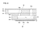
- the third embodiment of the liquid droplet ejection head of the present invention in which the above piezoelectric ceramic compositions is employed as a deflection type piezoelectric actuator utilizing a piezoelectric d 31 constant, will be described with reference to Fig. 6 .
- Fig. 6 is a schematic cross-sectional diagram of a liquid droplet ejection head of a type similar to the second embodiment in which the volume of a pressure chamber is altered by deformation due to expansion and contraction of a piezoelectric actuator which is provided on a wall of a pressure chamber, but it's structure differs from that of the second embodiment.
- the above liquid droplet ejection head is formed in such a manner that metallic nozzle plate 35, in which a plurality of nozzle orifices 35a are formed, and metallic supply plate 36, which is a member being provided on the liquid introduction side of pressure chamber 39 to restrict liquid flow and in which plate a plurality of liquid introduction ports 36a are provided.
- the metallic nozzle plates 35 and metallic supply plate 36 sandwich flow channel plate 32a between them and these plates were adhered to each other, whereby a liquid pressure chamber, which introduces liquid into above nozzle orifice 35a, and a liquid supply flow channel, which introduces liquid into above liquid introduction port 36a, are separately formed inside the head; and further, a member, which is formed by a laminated body of plates 32b, 32c, and 32d, made of metal or synthetic resin, and having a plurality of openings corresponding to each above nozzle orifice 35a and liquid introducing port 36a, is laminated onto the above structure, which are then bonded to form an integrated structure, whereby pressure chambers 39 are formed behind each of above nozzle orifice 35a and liquid introducing port 36a; and in addition, laminated body 33 is firmly fixed on a wall part of pressure chamber 39, which laminated body 33 is composed of lower electrode 33a, piezoelectric actuator 33b, which is made of above piezoelectric ceramic composition which was molded in a sheet form and sintered
- Liquid droplet ejection head 30 is structured so that liquid supplied to pressure chamber 39 is ejected through nozzle orifice 35a which is formed in nozzle plate 35. More specifically, droplet ejection head 30 is structured such that nozzle plate 35 and supply plate 36, which is a member exhibiting an opening at the liquid introducing side of the pressure chamber and restricting liquid flow, are laminated with flow channel plate 32a being sandwiched between them, and bonded by adhesives to form an integrated structure.
- a plurality of nozzle orifices 35a (not illustrated) for liquid ejection are formed in nozzle plate 35, as well as passing-through holes in the board thickness direction are formed in supply plate 36 and flow channel plate 32a at places corresponding to each of nozzle orifices 35a featuring a cavity being larger by a predetermined amount than that of the aforesaid nozzle orifice 35a.
- supply plate 36 In supply plate 36, a plurality of liquid introducing ports 36a (orifice holes) are formed, and window parts, which are provided at flow channel plate 32a, are covered with nozzle plate 35 and supply plate 36 from the both sides of the window, whereby a liquid supply flow channel, which is connected to each liquid introducing port 36a, is formed between above nozzle plate 35 and supply plate 36. Further, supply plate 36 is provided with a supply port which supplies liquid to a liquid supply flow channel, which liquid is introduced from a liquid storage tank.
- Liquid introducing port 36a is preferably formed as a tapered shape, as is illustrated in the figure, whose diameter decreases along the direction of liquid flow.
- each of the connecting openings is formed at places corresponding to a hole and liquid introducing port 36a, both of which are formed in supply plate 36.
- spacer plate 32c Within spacer plate 32c, a plurality of longitudinal rectangular window parts are formed. For each window part, spacer plate 32c is laminated to connecting plate 32b so that each of connecting openings provided in connecting plate 32b will feature an opening.
- closing plate 32d On the surface of above spacer plate 32c opposing to the side where connecting plate 32b is laminated, closing plate 32d is laminated, and the opening of the window part is covered with above closing plate 32d, whereby pressure chamber 39 is formed so that liquid is connected to the exterior through each of the connecting openings.
- Closing plate 32d, spacer plate 32c, and connecting plate 32b are preferably constituted of ceramic.
- alumina or zirconia are preferably employed in terms of formability.
- the thickness of closing plate 32d is preferably 50 ⁇ m or less, more preferably about 3 to 12 ⁇ m.
- the thickness of connecting plate 32b is preferably 10 ⁇ m or more, more preferably 50 ⁇ m or more,
- the thickness of spacer plate 32c is preferably 50 ⁇ m or more, more preferably 100 ⁇ m or more.
- Pressure chamber 39 thus formed is typically formed as an integrated sintered product of ceramics, but it may be made by bonding the respective plates employing adhesives.
- the laminated body 33 which is composed of lower part electrode 33a, piezoelectric actuator 33b, and upper part electrode 33a, is firmly fixed to closing plate 32d.
- a ceramic plate made of zirconium oxide as a primary component is preferably employed for closing plate 32d.
- the zirconium oxide is partially or wholly stabilized.
- the incorporating amount by addition of each compound into zirconium oxide is preferably from 2 to 7 mol% of yttrium oxide, from 6 to 15 mol% of cerium oxide, and from 5 to 12 mol% of magnesium oxide or calcium oxide.
- yttrium oxide it is particularly preferable to employ yttrium oxide as a partial stabilizer, and in which case, it is desirable to add from 2 to 7 mol%, more preferably from 2 to 4 mol%.
- the zirconium oxide in which yttrium oxide is added and incorporated in an amount of the above range, is partially stabilized in a crystal whose major crystalline phase is tetragonal, or in a mixed crystal comprised mainly of cubic and tetragonal resulting in excellent base characteristics.
- Electrodes films 33a and 33a are not particularly limited as long as they are conductors which can withstand an oxidation atmosphere of a high degree of thermal treatment temperature or sintering temperature, and they may be a metal element or an alloy, or may be a mixture of ceramics or glass with a metal or an alloy, or further, they may be conductive ceramics.
- electrode materials whose primary components are precious metals such as platinum, palladium, and rhodium which exhibit a high melting point or alloys such as silver/palladium, silver/platinum, or platinum/palladium.
- connecting plate 32d is laminated to supply plate 36 to form an integrated structure employing adhesives.
- Liquid droplet ejection head 30 is formed in such a manner that via an operation of piezoelectric actuator 33b on closing plate 32d, serving as a vibrating plate, liquid which is introduced through a liquid supply flow channel is supplied from liquid introducing port 36a into pressure chamber 39, so that the liquid passes a hole and is ejected from nozzle orifice 35a.
- Piezoelectric actuator 33b which is laminated to closing plate 32d, serving as a vibrating plate, is polarized in the thickness direction.
- the amount of displacement ⁇ of piezoelectric actuator 33b, at the time of ejection is represented by the formula below.
- ⁇ piezoelectric d 31 constant ⁇ xL ⁇ 1 ⁇ xV / T , wherein, as shown in Fig. 4 , L1 is the length of pressure chamber 39, V is a driving pulse voltage, and T is the thickness of piezoelectric actuator 33b.
- Piezoelectric actuator 33b in the liquid droplet ejection head employs piezoelectric ceramic compositions incorporating a solid solution of a primary component represented by Formula (1) below and a sub-component represented by Formula (2), also below, which is added in an amount of less than 1 mol% of the total amount of the solid solution.
- Formula (1) ⁇ Li X (K 1-Y Na Y ) 1-X ⁇ (Nb 1-Z-W Ta Z Sb W )O 3 , wherein x, y, z and W are within the ranges of 0 ⁇ x ⁇ 0.2, 0 ⁇ y ⁇ 1, 0 ⁇ z ⁇ 0.4, and 0 ⁇ w ⁇ 0.2, respectively.
- Formula (2) ABO 3 , wherein A represents Bi, and B represents at least any one of Fe, In, and Sc.
- a change of displacement properties of the piezoelectric actuator is small even if temperature change takes place, and liquid ejection properties are stabilized.
- the above piezoelectric ceramic composition contains no lead in its composition, toxic lead does not eluted off from the waste thereof. Therefore, the above piezoelectric ceramic composition can be one which contains no lead and exhibits high safety.
- the liquid droplet ejection head of the present invention can be widely utilized for not only inkjet heads which are employed for inkjet printers, but industrial applications such as creations of electronic circuits, production of color filters for liquid crystal displays, and production of organic EL displays.
- the piezoelectric ceramic compositions relating to examples of the present invention are produced, and the characteristics thereof were evaluated.
- the compounded raw materials were blended via a ball mill in anhydrous acetone over 24 hours, and then dried to produce a mixture.
- the above mixture was calcined at 750 °C over 5 hours, which mixture was then subjected to pulverization via a ball mill over 24 hours.
- the pulverized mixture was dried to produce calcined powder of the primary component.
- a piezoelectric ceramic composition in which each component was compounded was mixed via a ball mill in anhydrous acetone over 24 hours, and then dried to produce a mixture.
- the above mixture was calcined at from 700 to 800 °C over 5 hours, which was then subjected to pulverization via a ball mill over 24 hours.
- polyvinyl butyral as a binder was added thereto, and then the mixture was granulated and subjected to pressure molding.
- the pressure molding was carried out in such a manner that the granulated substance, made of the pulverized substance, was molded in the form of pellets via uniaxial pressing, and then the resultant pellets were re-molded via a cold isostatic press (CIP) at a pressure of 1 ton/cm 2 .
- CIP cold isostatic press
- the compacted pellets thus produced were sintering at from 1,000 to 1,300 °C over one hour to produce a sintered product.
- the temperature, at which the highest density was yielded, was selected between 1,000 and 1,300 °C as the sintering temperature.
- a highly dense sintered substance was not provided from a mixture exhibiting the above formula ⁇ Li 0.04 (K 0.48 Na 0.52 ) 0.96 ⁇ (Nb 0.84 Ta 0.1 Sb 0.06 )O 3 to which the amount of the sub-component added was 1 mol%.
- the crystalline phase of the resulted sintered substance was identified via x-ray diffraction analysis.
- the generation of a solid solution in the sintered substance composed of the piezoelectric ceramic composition of the present invention was confirmed from the fact that the diffraction peak was indicative of single-phase structure of a perovskite and successively shifted with the increase of the amount of the sub-component.
- the obtained sintered product was cut to a predetermined size, which was then subjected to parallel grinding to about 0.5 mm in thickness, followed by formation of gold electrodes via sputtering on both sides thereof. Subsequently, in silicone oil at about from 80 to 150 °C, direct current voltage of from 1 to 6 kV/mm was applied between the electrodes to be polarized in the thickness direction to produce a piezoelectric ceramic composition.
- a temperature dependence of a piezoelectric d 31 constant in a temperature range of from -30 to 80 °C was determined.
- the piezoelectric d 31 constant was determined via a resonance-anti-resonance method employing an impedance analyzer (type 4294A: manufactured by Agilent Technologies Inc.). Specifically, employing an impedance analyzer and a thermostat bath, after the sample was held for a predetermined time at every 2 to 5 °C interval in a range of from -30 to 80 °C, the piezoelectric d 31 constant was determined at each temperature.
- the rate of change ⁇ d of the piezoelectric d 31 constant between 10 and 80 °C was calculated from the obtained graph of temperature dependence.
- the ⁇ d was calculated by a formula below based on values measured at the temperatures of T1 (°C) at which the piezoelectric d 31 constant reaches its maximum value and T2 (°C) at which the piezoelectric d 31 constant reaches its minimum value.
- the temperature dependence was evaluated with respect to the ⁇ d, and it was judged that the larger the ⁇ d, the larger the temperature dependence of the piezoelectric d 31 constant.
- ⁇ d piezoelectric d 31 constant at T ⁇ 1 - piezoelectric d 31 constant at T ⁇ 2 / ⁇ T , wherein, ⁇ T (in absolute value) is a temperature difference between T1 and T2.
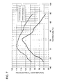
- Fig. 7 shows a temperature dependence of the piezoelectric d 31 constant measured on samples No. 1 and No. 12.
- sample No. 1 the maximum piezoelectric d 31 constant in a range of from 10 to 80 °C reaches about 108 pc/N at 21 °C, and the minimum is about 83 pc/N at 80 °C.
- These values give as much as 0.42 of the rate of change ⁇ d of the piezoelectric d 31 constant between 10 and 80 °C.
- the phase transition temperature from orthorhombic to tetragonal is about 21 °C.
- the crystalline phase is orthorhombic at 10 °C and tetragonal at 30 °C from the above-described result of crystalline phase identification of the sintered substance via x-ray diffraction analysis (XRD).
- the maximum piezoelectric d 31 constant in a range of from 10 to 80 °C reaches about 114 pc/N at 10 °C, and the minimum is about 97 pc/N at 80 °C.
- These values give as little as 0.24 of the rate of change ⁇ d of the piezoelectric d 31 constant between 10 and 80 °C.
- the phase transition temperature from orthorhombic to tetragonal is about 5 °C.
- the crystalline phase is orthorhombic at 0 °C and tetragonal at 20 °C from the above described result of crystalline phase identification of the sintered substance via x-ray diffraction analysis (XRD).
- the temperature dependence of the piezoelectric constant largely varies in the vicinity of the transition temperature of the piezoelectric ceramic composition, and then, the transition temperature of the piezoelectric ceramic composition is required to be lowered from the vicinity of the using temperature range where the piezoelectric ceramic composition is used to allow the characteristics thereof to be stabilized.
- the transition temperature of the piezoelectric ceramic composition of sample No. 12, in which a sub-component is added to form solid solution decreases to about 5 °C which is away from the using temperature range where the piezoelectric ceramic composition is used, whereby the temperature dependence of the piezoelectric constant in the using temperature range where the piezoelectric ceramic composition is used can be significantly lowered.
- the other samples of the present invention exhibit a tendency on the temperature dependence similar to that of sample No. 12 in Fig. 7 , which indicates that each of the samples of the present invention exhibits smaller temperature dependence of the piezoelectric constant due to addition of the sub-component.
- the piezoelectric ceramic compositions of the present invention exhibit a small temperature dependence of the piezoelectric d 31 constant. This allows that, with a droplet ejection head which is provided with a piezoelectric actuator employing the aforesaid piezoelectric ceramic composition, the piezoelectric actuator exhibits a small change in displacement properties leading to stabilized ejection properties of liquid even if temperature change takes place.
- (Li 0.04 (K 0.48 Na 0.52 ) 0.96 ⁇ (Nb 0.84 Ta 0.1 Sb 0.06 )O 3 , ⁇ Li 0.2 (K 0.5 Na 0.5 ) 0.8 ⁇ (Nb 0.84 Ta 0.1 Sb 0.06 )O 3 , or (Li 0.1 (K 0.5 Na 0.5 ) 0.9 ⁇ (Nb 0.64 Ta 0.3 Sb 0.06 )O 3 was employed as a primary component, but any components, as long as they are represented by a formula ⁇ Li X (K 1-Y Na Y ) 1-X ⁇ (Nb 1-Z-W Ta Z Sb W )O 3 , wherein x, y, z and w are within the ranges of 0 ⁇ x ⁇ 0.2, 0 ⁇ y ⁇ 1, 0 ⁇ z ⁇ 0.4, and 0 ⁇ w ⁇ 0.2, respectively, may be applicable as the primary component and can give similar effects.
- a sub-component was added as a form of mixed powder, but addition of a sub-component as calcined powder, which was produced in advance by temporarily calcinating the sub-component, also can give similar effects.
Landscapes
- Engineering & Computer Science (AREA)
- Chemical & Material Sciences (AREA)
- Ceramic Engineering (AREA)
- Manufacturing & Machinery (AREA)
- Materials Engineering (AREA)
- Structural Engineering (AREA)
- Organic Chemistry (AREA)
- Particle Formation And Scattering Control In Inkjet Printers (AREA)
- Compositions Of Oxide Ceramics (AREA)
Abstract
Description
- The present invention relates to a liquid droplet ejection head.
- Heretofore, a PZT (PbTO3-PbZrO3) constituent-based ceramic containing lead has been used in a piezoelectric ceramic composition. The reason for it is that the aforesaid PZT, exhibiting excellent piezoelectric properties and a high mechanical quality coefficient, can readily produce materials exhibiting various desired characteristics which are required for various applications such as a sensor, an actuator, and a filter. Further, since the PZT has a high relative dielectric constant, it may also be used as a capacitor.
- However, while the piezoelectric ceramic composition composed of the aforesaid PZT exhibits excellent characteristics, it contains lead as an element constituting the composition, leading to a concern that toxic lead is eluted off from industrial waste of products containing PZT to result in an environmental pollution. The increasing awareness of environmental issues in recent years has made it difficult to manufacture the products containing substances such as PZT which have been a cause of environmental pollution. To cope with the above problem, piezoelectric ceramic compositions have been developed which include no lead in their compositions and whose primary component is a chemical compound which is represented by formula {LiX(K1-YNaY)1-X}(Nb1-Z-WTaZSbW)O3, wherein x, y, z and w are within the ranges of 0≤x≤0.2, 0≤y≤1, 0<z≤0.4, and 0<w≤0.2, respectively (refer to Patent Document 1).
- A polarization method has been disclosed in which the first step where a piezoelectric ceramic composition, exhibiting a cubic crystal structure at a high temperature and a reversible phase transition to tetragonal and then to orthorhombic structures when the temperature decreased, is subjected to the first polarization processing, and the second step where the above piezoelectric ceramic composition is subjected to the second polarization processing in a temperature range in which the composition exhibits an orthorhombic structure and in the same direction of polarization as the above first polarization processing are provided in the piezoelectric ceramic composition in which the primary component described above exhibits a perovskite structure of ABO3 type to stably increase and saturate the polarization degree (refer to Patent Document 2).
- Further,
patent document 3 discloses a liquid droplet ejection head utilizing a piezoelectric actuator whose primary component is a piezoelectric ceramic composition having a perovskite crystal structure and including no lead. It also discloses that the above primary component includes barium titanate, potassium niobate, sodium bismuth titanate, bismuth nickel titanate, Ba2NaNb5O15, and Bi4Ti3O12. - Patent Document 1: Japanese Patent Application Publication (hereinafter also referred to as JP-A) No.
2004-300012 - Patent Document 2:
JP-A No. 2005-228865 - Patent Document 3:
JP-A No. 2005-246656 - In recent years, along with expansion of utilization fields of the piezoelectric actuator, stable characteristics of the piezoelectric actuator over a wider temperature range have been demanded. In particular, the temperature stability of a piezoelectric constant which contributes to a piezoelectric displacement has been demanded.
- For example, in case where a piezoelectric ceramic composition is employed in the piezoelectric actuator for a liquid droplet ejection head, the piezoelectric actuator is possibly demanded to exhibit stable characteristics over a wider temperature range, for example, as much as from 10 to 80 °C, corresponding to the use environment.
- However, the piezoelectric ceramic compositions including no lead, which are described in
patent documents patent document 2 is employed due to a large temperature dependence of the piezoelectric constant, under present circumstances that the temperature range of the use of the liquid droplet ejection head has been extended to a higher side. - In other words, in case where the piezoelectric ceramic composition exhibiting a large temperature dependence of the above piezoelectric constant is employed, a change of the piezoelectric constant occurs when the temperature changes. Then, there exist a problem that, with the temperature change, displacement properties of the piezoelectric actuator vary to result in changes of liquid ejection properties.
- The present invention has been achieved in consideration of such problems, and it is an object to provide a liquid droplet ejection head which is provided with a piezoelectric actuator employing a piezoelectric ceramic composition including no lead exhibiting a small temperature dependence of the piezoelectric constant.
- The above issue of the present invention can be achieved by a constitution below.
- 1. A liquid droplet ejection head wherein there is provided a piezoelectric actuator employing a piezoelectric ceramic composition incorporating a solid solution of a primary component represented by Formula (1) below and a sub-component represented by Formula (2), also below, which is added in an amount of less than 1 mol% of the total amount of the solid solution.
Formula (1) : {L1X(K1-YNaY)1-X} (Nb1-Z-WTaZSbW)O3,
wherein x, y, z and W are within the ranges of 0≤x≤0.2, 0≤y≤1, 0<z≤0.4, and 0<w≤0.2, respectively.
Formula (2): ABO3,
wherein A represents Bi, and B represents at least any one of Fe, In, and Sc. - 2. The liquid droplet ejection head of
Configuration 1,
wherein the solid solution exhibits a perovskite structure. - 3. The liquid droplet ejection head of
Configuration
wherein the piezoelectric actuator is employed as a shear mode piezoelectric actuator utilizing a piezoelectric d15 constant. - 4. The liquid droplet ejection head of
Configuration
wherein the piezoelectric actuator is employed as a deflection piezoelectric actuator utilizing a piezoelectric d31 constant. - 5. The liquid droplet ejection head of
Configuration
wherein the piezoelectric actuator is employed as a push piezoelectric actuator utilizing a piezoelectric d31 constant. - 6. The liquid droplet ejection head of
Configuration - According to the present invention, by adding a sub-component represented by ABO3 perovskite (Wherein A represents Bi, and B represents at least any one of Fe, In, and Sc.) which is added in an amount of less than 1 mol% of the total amount of the solid solution into {LiX(K1-YNaY)1-X}(Nb1-Z-WTaZSbW)O3 (Wherein x, y, z and W are within the ranges of 0≤x≤0.2, 0≤y≤1, 0<z≤0.4, and 0<w≤0.2, respectively.) which is a piezoelectric ceramic composition including no lead to form a solid solution, the temperature dependence of the piezoelectric constant of the resulting piezoelectric ceramic composition can be reduced. This allows a change of displacement properties of the piezoelectric actuator of a liquid droplet ejection head which is provided with a piezoelectric actuator employing the aforesaid piezoelectric ceramic composition to be minimized even if temperature change takes place and liquid ejection properties to be stabilized.
-
-
Fig. 1 : A diagram illustrating a constitution of the liquid droplet ejection head of the first embodiment of the present invention -
Fig. 2 : A diagram illustrating a constitution of the liquid droplet ejection heads exhibiting multi-nozzles of the first embodiment of the present invention -
Fig. 3 : A diagram illustrating motions of the liquid droplet ejection heads shown inFig. 1 and Fig. 2 -
Fig. 4 : A diagram illustrating a constitution of the liquid droplet ejection heads of the second embodiment of the present invention -
Fig. 5 : A diagram illustrating a deformation example of a constitution of the liquid droplet ejection heads of the second embodiment of the present invention -
Fig. 6 : A diagram illustrating a constitution of the liquid droplet ejection head of the third embodiment of the present invention -
Fig. 7 : A figure showing a temperature dependence of a piezoelectric d31 constant of a piezoelectric ceramic composition -
- 1: liquid tube
- 2: nozzle forming member
- 3: nozzle
- 6: cover plate
- 7: liquid supply port
- 9: substrate
- An embodiment of the liquid droplet ejection head which is provided with the piezoelectric actuator of the present invention will now be described.
- The piezoelectric actuator of the present embodiment is characterized in that the piezoelectric actuator employs piezoelectric ceramic composition incorporating a solid solution of a primary component represented by Formula (1) below and a sub-component represented by Formula (2) below which is added in an amount of less than 1 mol% of the total amount of the solid solution.
Formula (1) : {LiX(K1-YNaY)1-X}(Nb1-Z-WZaZSbW) O3,
wherein x, y, z and W are within the ranges of 0≤x≤0.2, 0≤y≤1, 0<z≤0.4, and 0<w≤0.2, respectively.
Formula (2) : ABO3,
wherein A represents Bi, and B represents at least any one of Fe, In, and Sc. - First, an embodiment of the piezoelectric ceramic composition of the present invention is described below.
- Each component will be described below.
- The primary component of the present embodiment is represented by above Formula (1). In the case of x>0.2, z>0.4, w>0.2, z=0, or w=0, piezoelectric properties such as a piezoelectric constant and dielectric properties decrease, whereby a piezoelectric ceramic composition exhibiting desired properties may not be obtained.
- Such a primary component can be provided by preparing raw materials containing each metal element as the raw material, and then the materials being sufficiently blended by, for example, a ball mill. Raw materials for the primary component include, for example, Li2CO3, Li2O, LiNO3, and LiOH as a Li containing compound; Na2CO3, NaHCO3, and NaNO3 as a Na containing compound; K2CO3, KNO3, KNbO3, and KTaO3 as a K containing compound; Nb2O5, Nb2O3, and NbO2 as a Nb containing compound; Ta2O5 as a Ta containing compound; and Sb2O5, Sb2O3, and Sb2O4 as a Sb containing compound.
- The primary component features a perovskite structure (ABO3), and elemental constitution of the A site corresponds to K, Na and Li, and elemental constitution of the B site corresponds to Nb, Ta, and Sb.
- A composition of the perovskite structure becomes a perfect perovskite structure when the stoichiometric ratio between atoms constituting the A site and atoms constituting the B site is 1 : 1. But in the case of a piezoelectric ceramic composition, it may happen that, in particular, several percent of the amount of K, Na, Li or Sb volatilize during the sintering step, or all constituting elements vary in several percent during the production steps such as a mixing pulverization step or a granulation step. In other words, deviation from a stoichiometric composition may happen due to variation in production.
- In response to such a variation in the composition during manufacturing steps, intentional alteration of the ratio of composition of compounded material enables the ratio of the composition of the sintered piezoelectric ceramic composition to vary by ± several percents, specifically by ±3 to ±5%. The similar alteration may be done to, for example, the conventional lead zirconium titanate (PZT), and the compounding ratio may be regulated in consideration of vaporization of lead during sintering or incorporation of zirconia from zirconia balls which is a pulverization medium.
- In the piezoelectric ceramic composition incorporating the primary component of the present embodiment, electrical characteristics such as piezoelectric properties do not vary largely, even if the ratio of composition of compounded material is intentionally altered in such a way as mentioned above. Therefore, in the present invention, when the primary components are fitted to the composition formula ABO3 of a perovskite structure, the constitution ratio of atomic elements at the A and B sites can deviate from 1 : 1 by as much as about ±5 mol% for each site. In order to achieve high electrical characteristics by allowing the amount of lattice defects in a constituted crystal to be reduced, the amount of the deviation of the constitution ratio of the composition is preferably about ±3%. That is, in the constitution represented by formula {LiX(K1-YNaY)1-X}a(Nb1-Z-WTaZSbW)}bO3, the primary components are 0.95≤a, and b≤1.05, preferably 0.97≤a, and b≤1.03.
- In the primary components represented by the above formula, 0<x≤0.2 is preferable. Since this allows the Li to be an essential component, the sintering of the resulting piezoelectric ceramic composition can be more readily carried out, and at the same time, the piezoelectric properties thereof can be enhanced and Curie temperature Tc can be further increased. The reason for it is that by allowing the Li to be an essential component within the above-described range, the sintering temperature can be decreased, and, at the same time, Li plays a role of a sintering additive, whereby sintered producing a less void substance can be achieved.
- In the primary components represented by the above formula, x=0 is allowed. In this case, the primary component is represented by (K1-YNaY) (Nb1-Z-WTaZSbW) O3. Since the piezoelectric ceramic composition incorporating such a primary component does not contain in their raw materials the lightest element of Li as a lithium compound such as LiCO3, variation in properties due to segregation of raw material powder is allowed to be small when the raw materials are blended to produce the above piezoelectric ceramic compositions. In addition, a high relative dielectric constant εr, as well as a relatively large piezoelectric constant may be realized.
- In order to further increase piezoelectric constant and electromechanical coupling coefficient of the resulting piezoelectric ceramic composition, "y" is preferably in the range of 0≤y≤0.85, more preferably in the range of 0.05≤y≤0.75, further more preferably in the range of 0.35≤y≤0.65, and yet further, "y" is most preferably in the range of 0.42≤y≤0.60.
- In the primary components represented by the above formula, y=0 is viable. In which case, Na is not incorporated in the primary component, which results in a decrease of dielectric loss and enhancement of long term stability of dielectric loss of the resulting piezoelectric ceramic composition.
- In the primary components represented by the above formula, the total of z+w is preferably in a range of z+w≤0.37. In which case, piezoelectric properties such as a piezoelectric constant are allowed to be further enhanced.
- Next, a sub-component of the present embodiment will be described.
- The sub-component of the present embodiment is represented by Formula ABO3, and is a perovskite compound of the ABO3 type, wherein A and B are a metal element exhibiting a valence of +3. Further, the A in the sub-component is an element Bi, and the B contains at least any one of elements Fe, In, and Sc. In order to produce a highly dense sintered substance during the sintering step of a piezoelectric ceramic composition, the amount of the sub-component to be added is preferably less than 1 mol per 100 mol of the total components (total of primary components and subcomponents) after the sub-component has been added.
- The sub-component represented by the above Formula (2) may be added to the primary component in the form of a compound constituting a perovskite compound of the ABO3 type, or the sub-component may be added in the step where the sub-component is blended with the primary component in the form of a combination of raw materials which will become an ABO3 type perovskite compound. Compounds which originally constitute a perovskite structure of the ABO3 type include BiInO3, BiFeO3, and BiScO3.
- Raw materials which can become an ABO3 type perovskite compound at the blending step include; Bi2O3 as a Bi containing compound; In2O3 as an In containing compound; Sc2O3 as a Sc containing compound; and Fe2O3 as an Fe containing compound. Highly pure raw materials of at least 99% are preferred.
- The sub-component of the present embodiment is an ABO3 type perovskite compound. The atomic element which constitutes the A site is Bi. The atomic element which constitutes the B site is at least any one of Fe, In, and Sc, and the above atomic element is not limited to one metal element but the B site may be constituted with a combination of at least two metal elements thereof.
- Further, raw materials of the sub-component may be compounded in a stoichiometric ratio of 1 : 1 between elements constituting the A site and elements constituting the B site to form ABO3, or the stoichiometric ratio may be allowed to vary by ± several percent in consideration of variation during production such that the metal element such as Bi vaporizes during the sintering step.
- Next, a method for producing the piezoelectric ceramic composition of the present embodiment will be described. The method for producing the piezoelectric ceramic composition is not particularly limited, but the production method via a solid phase thermochemical reaction will be described.
- First, raw materials of the primary component are prepared and fully dried. The dried raw materials, the weight of each of which being in the stoichiometric ratio of ABO3, are blended via a ball-mill, and then dried. Then, the resulting mixture is calcined at 700 to 1,000 °C to decompose and solidify the raw materials via a solid phase thermochemical reaction. The resulting calcined mixture is wet-pulverized into fine particles having a center of the particle size distribution of about 5 µm, and is dried to produce a calcined powder of the primary component.
- Next, raw materials of the sub-component are prepared and fully dried. The dried raw materials, the weight of each of which being in the stoichiometric ratio of ABO3, are subjected to wet mixing to produce a mixed powder of the sub-component.
- Subsequently, the calcined powder of the primary component and the mixed powder of the sub-component are compounded so that "v" falls within the range of 0<v< 0.01 in formula [{LiX(K1-YNaY)1-X}(Nb1-Z-WTaZSbW)O3]1-V(ABO3)V. The compounded material is fully blended via, for example, a ball-mill, and then dried to produce a blended substance.
- The resulting blended substance is calcined at from 700 to 800 °C, and then the calcined blended substance is pulverized. An organic bonding agent such as a binder is added to the pulverized substance, which is then granulated and subjected to a pressure molding. The aforesaid pressure molding is preferably carried out in such a manner that the granulated substance made of the above pulverized substance is molded into the form of pellets via uniaxial pressing, and then the resulting pellets are re-molded via a cold isostatic press (CIP).
- The compact thus obtained is sintered at from 1,000 to 1,300 °C to produce a sintered product. The resulted sintered product is cut to a predetermined size, which is then subjected to a parallel grinding to form electrodes via sputtering on both sides thereof. Subsequently, in silicone oil at about from 80 to 150 °C, direct current voltage of from 1 to 6 kV/mm is applied between the electrodes to polarize them in the thickness direction to produce a piezoelectric ceramic composition.
- As stated above, according to the piezoelectric ceramic composition of the present embodiment, addition of at least two metal elements as a sub-component in a combination represented by ABO3 (wherein the A is Bi, and the B is at least any one of Fe, In, and Sc) exhibiting a perovskite structure, significantly decreases a temperature dependence of the piezoelectric constant of the resulting piezoelectric ceramic composition. The reason for such decrease is considered to be that when Bi is added in a form of Bi2O3 alone, the valence of Bi becomes +5, and the B site tends to be replaced by the Bi, while when Bi is added in a form of a combination of ABO3 (for example, BiFeO3) which is known to exhibit a perovskite structure, the valence of Bi becomes +3, and the A site tends to be replaced by the Bi.
- According to a liquid droplet ejection head which is provided with a piezoelectric actuator employing such a piezoelectric ceramic composition, a change of displacement properties of the piezoelectric actuator is small even if temperature change takes place, and liquid ejection properties are stabilized.
- The amount of displacement of such a piezoelectric actuator is proportional to the product of the piezoelectric constant and the applied voltage. The liquid droplet ejection head, which allows ejection of liquid, can take various forms by allowing displacement of the piezoelectric actuator, and they will be described below by listing examples of a shear mode type utilizing a piezoelectric d15 constant, a deflection type utilizing a piezoelectric d31 constant, a push type, and a push type utilizing a piezoelectric d33 constant.
- Below, the first embodiment of the liquid droplet ejection head of the present invention employing the above piezoelectric ceramic composition as the piezoelectric actuator of the shear mode type utilizing a piezoelectric d15 constant is described with reference to
Fig. 1 to Fig. 3. Fig. 1 is a diagram illustrating a constitution of the liquid droplet ejection head of the first embodiment of the present invention.Fig. 2 is a diagram illustrating a constitution of the liquid droplet ejection heads having multiple nozzles of the first embodiment of the present invention.Fig. 3 is a diagram illustrating motions of the liquid droplet ejection heads shown inFig. 1 and Fig. 2 . - In the liquid droplet ejection head of the present embodiment, many pressure chambers are arranged, each of which has a nozzle to eject a liquid and is separated by dividing walls. Some or all of the aforesaid dividing walls are constituted of a piezoelectric actuator of the shear mode type, and then, all or some of the surfaces of the dividing walls form an electrode onto which a driving pulse is applied. Application of the driving pulse to the above electrode causes a shear deformation on the above dividing wall, whereby pressure inside the above pressure chamber changes to result in ejection of droplets from the above nozzle which is formed at one end of the above pressure chamber.
- In
Fig. 1 to Fig. 3 , each of numerals from 1 to 11 designates: - 1: liquid tube
- 2: nozzle forming member
- 3: nozzle
- 4: pressure chamber
- 5: piezoelectric dividing wall (being a shear mode piezoelectric actuator)
- 6: cover plate
- 7: liquid supply port
- 8: shared liquid chamber
- 9: substrate, and
- 10 and 11: electrodes
-
Pressure chamber 4 is formed ofpiezoelectric dividing wall 5,cover plate 6, andsubstrate 9. - First, two pieces of the above piezoelectric ceramic composition are prepared, which have been molded in a sheet form and then sintered to allow it to be polarized in the thickness direction.
Substrate 9 and the two pieces of piezoelectric ceramic compositions, which are overlaid so that the direction of polarization thereof differ from each other, are pasted together above and below viaadhesive 100. Then, the upper part of the laminated compositions is subjected to a cutting process employing a diamond blade in such a manner that all of the plurality ofpressure chambers 4, exhibiting a groove-like structure, have the same form and are parallel to each other. Due to the above processing,adjacent pressure chambers 4 are divided by piezoelectric dividing walls 5 (being a shear mode piezoelectric actuator) which are polarized in the direction of the arrows. Then, afterelectrodes piezoelectric dividing walls 5 via a plating method or a vapor-phase deposition method,cover plates 6 are pasted onto the upper surface, followed bynozzle forming members 2 being pasted onto the front surface. -
Fig. 1 shows a liquid droplet ejection head exhibiting one unit of the pressure chamber and one piece of nozzle. However, in an actual liquid droplet ejection head, a plurality ofpressure chambers 4, which are divided betweencover plate 6 andsubstrate 9 by a plurality of piezoelectric dividing walls, are formed parallel to each other, one end ofpressure chamber 4 is connected tonozzle 3, which is formed throughnozzle forming member 2, andliquid supply port 7 located at the other end ofpressure chamber 4 is connected to a liquid tank (not illustrated) byliquid tube 1 through sharedliquid chamber 8. Driving pulse voltage is applied betweenelectrode 10 and groundedelectrode 11, both of which are formed to be in tight contact withpiezoelectric dividing walls 5. - In
Fig. 2(a) ,piezoelectric dividing wall 5 is constituted of twopiezoelectric dividing walls Fig. 2(a) , when no driving pulse is applied toelectrode 10,piezoelectric dividing walls Fig. 2(b) and Fig. 3 , when a driving pulse is applied toelectrode 10, shear stress occurs due to the electric field in a direction perpendicular to the polarized direction of the piezoelectric dividing wall, which causes shearing strain at the joint surfaces of bothpiezoelectric dividing walls pressure chamber 4 caused by the above shearing strain, some of the liquid which fillpressure chamber 4 are ejected vianozzle 3. The average amount of displacement Δ of the piezoelectric dividing wall and generated pressure P, at the time of ejection, are represented by the formulae below.

Fig. 3 , H is the depth ofpressure chamber 4, W is the width ofpressure chamber 4, V is a driving pulse voltage, T is the thickness ofpiezoelectric dividing wall 5, B is a modulus of volume elasticity of the liquid, and S is the cross-sectional area ofpressure chamber 4. - Supply of liquid from a liquid tank to a nozzle after droplets have been ejected is carried out through a liquid supply port and
pressure chamber 4 by force of capillary action at the nozzle. -
Piezoelectric dividing wall 5 in the liquid droplet ejection head employs a piezoelectric ceramic composition incorporating solid solution of a primary component represented by Formula (1) below, and a sub-component represented by Formula (2), also below, which is added in an amount of less than 1 mol% of the total amount of the solid solution.
Formula (1) : {LiX(K1-YNaY)1-X} (Nb1-Z-WTaZSbW) O3,
wherein x, y, z and W are within the ranges of 0≤x≤0.2, 0≤y≤1, 0<z≤0.4, and 0<w≤0.2, respectively.
Formula (2) : ABO3,
wherein A represents Bi, and B represents at least any one of Fe, In, and Sc. - By employing a piezoelectric ceramic composition exhibiting a low temperature dependence of the piezoelectric d15 constant such as described in the present embodiments as a piezoelectric dividing wall (being a shear mode piezoelectric actuator), a change of displacement properties of the piezoelectric actuator is small even if temperature change takes place, whereby liquid ejection properties remain stable.
- Since the above piezoelectric ceramic composition contains no lead in its composition, toxic lead is not eluted off from the wastes thereof. Therefore, the above piezoelectric ceramic composition can be one which contains no lead and exhibits high safety.
- The shear mode type piezoelectric actuator utilizing a piezoelectric d15 constant employing the above piezoelectric ceramic composition can be applied to a liquid droplet ejection head below as a deformation example of the first embodiment of the liquid droplet ejection head of the present invention.
- In the above deformation liquid droplet ejection head, a plurality of pressure chambers provided with nozzles are divided by dividing walls, and the above pressure chambers are formed by above two dividing walls, a wall combining the aforesaid two dividing walls, and a wall in which above nozzle is formed. And at least one of the above combining walls is constituted with the shear mode type piezoelectric actuator, and over the whole or some of the surfaces of the piezoelectric actuator, formed are electrodes to which a driving pulse is applied. Application of the driving pulse to the above electrodes causes shear deformation of the above piezoelectric actuator, whereby the pressure inside the above pressure chamber changes to result in ejection of liquid droplets from the above nozzle which is formed at one end of the above pressure chamber.
- Hereinafter, the second embodiment of the liquid droplet ejection head of the present invention, in which the above piezoelectric ceramic composition is employed as a push type piezoelectric actuator utilizing a piezoelectric d31 constant, is described with reference to
Fig. 4 . -
Fig. 4 is a schematic cross-sectional diagram of a liquid droplet ejection head of a type such that the volume of a pressure chamber is altered by deformation due to expansion and contraction of a piezoelectric actuator which is provided on a wall of a pressure chamber. - At one end of
base 21b, which is in a lower part of the figure, formed is a protruding portion at one side of the base, which portion fixeslaminated body 23 comprisingpiezoelectric actuator 23a andelectrode 23b (hereinafter described as laminated body 23) which will be described later. At the surface of an upper end ofbase 21b, fixed is vibratingplate 24 which separatespressure chamber 29 fromlaminated body 23. - Vibrating
plate 24 is formed so as to readily respond to vibration oflaminated body 23 by forming concave portions near places which make close contacts withlaminated body 23. On the surface of vibratingbody 23, fixed are a pressure chamber forming member as well asspacer member 22, which also functions as a supply board havingliquid introducing port 26a. The area facinglaminated body 23 is constituted to form a pressure chamber in conjunction with vibratingplate 24. Further,liquid introducing port 26a is formed, though it is not illustrated, such that the pressure chamber becomes narrower in the direction ofpressure chamber 29 to restrict liquid flow. - On the surface of
spacer member 22, fixed isnozzle plate 25, and there are provided a plurality of nozzle orifices coordinating with an array form oflaminated body 23 in which each ofpiezoelectric actuators 23a andelectrodes 23b is alternatively laminated in a layer form. Further, in a liquid supply section,liquid supply part 27 is formed in such a manner that opening parts, wherenozzle orifices 25a innozzle plate 25 are not provided, are sealed. - One end of
laminated body 23 is fixed onto vibratingplate 24 in such a state that each ofpiezoelectric actuators 23a comprising above-described piezoelectric ceramic composition, which is molded in a sheet form and sintered to allow it to be polarized in a thickness direction, andelectrodes 23b are alternatively laminated in a layer form, and the side part of the other end is fixed to the protruding portion ofbase 21b. The lower end ofbase 21b is fixed to fixingmember 21a. Fixingmember 21a supports vibratingplate 24,spacer member 22, andnozzle plate 25, and, throughbase 21b, brings an unfixed end of laminated body 23 (an upper end in the figure) into contact with vibratingplate 24. Further, as the figure clearly shows,base 21b is constituted such that one end ofbase 21b almost meets to a surface at an end of the unfixed end oflaminated body 23, and the size of the other end ofbase 21b is such that it protrudes farther than the fixed end oflaminated body 23. In liquid droplet ejection head exhibiting the above structure, when a voltage is applied betweenelectrode 23b andelectrode 23b located at both surfaces of eachpiezoelectric actuator 23a,laminated body 23 is stretched to the axial direction perpendicular in the electric field direction, and then, vibratingplate 24 which is fixed to the end oflaminated body 23 is stretched and displaced in the direction ofnozzle plate 25 to result in pressurizingpressure chamber 29. The liquid, which is subjected to a higher pressure due to decrease in volume ofabove pressure chamber 29, is ejected fromnozzle orifice 25a as liquid droplets. At that time, the amount of displacement Δ oflaminated body 23 is represented by the formula below.
wherein, as shown inFig. 4 , L0 is the length of the active part, V is a driving pulse voltage, and T is the thickness ofpiezoelectric actuator 23a. - Supply of liquid from a liquid storage tank to a nozzle after liquid droplets have been ejected is carried out through a liquid supply port and
pressure chamber 4 by force of capillary action of the nozzle. -
Piezoelectric actuator 23a in the liquid droplet ejection head employs a piezoelectric ceramic composition incorporating a solid solution of a primary component represented by Formula (1) below and a sub-component represented by Formula (2), also below, which is added in an amount of less than 1 mol% of the total amount of the solid solution.
Formula (1) : {LiX(K1-YNaY)1-X}(Nb1-Z-WTaZSbW) O3,
wherein x, y, z and W are within the ranges of 0≤x≤0.2, 0≤y≤1, 0<z≤0.4, and 0<w≤0.2, respectively.
Formula (2): ABO3,
wherein A represents Bi, and B represents at least any one of Fe, In, and Sc. - By employing a piezoelectric ceramic composition exhibiting a low temperature dependence of the piezoelectric d15 constant such as described in the present embodiments as a piezoelectric actuator, a change of displacement properties of the piezoelectric actuator is small even if temperature change takes place, and liquid ejection properties are stabilized.
- Since the above piezoelectric ceramic composition contains no lead in its composition, toxic lead is not eluted off from the waste thereof. Therefore, the above piezoelectric ceramic composition can be one which contains no lead and exhibits high safety.
- In the present embodiment, exemplified is a liquid droplet ejection head, in which the piezoelectric ceramic composition is employed as a push type piezoelectric actuator utilizing a piezoelectric d31 constant, but the piezoelectric ceramic composition is not limited thereto. It can also be applied to a liquid droplet ejection head which is a deformation example of the second embodiment shown below.
- Below, a deformation example of the second embodiment of the liquid droplet ejection head of the present embodiment employing the above piezoelectric ceramic composition as a push type piezoelectric actuator utilizing a piezoelectric d33 constant will be described with reference to
Fig. 5 . - In
Fig. 5 , with regard to the members exhibiting the same functions as the liquid droplet ejection head of the second embodiment inFig. 4 , the same symbols are used, and their detailed descriptions will be omitted. In the present deformation example,piezoelectric actuator 23a andelectrode 23b are laminated along the length oflaminated body 23, and one end of the longitudinal direction is secured to fixingmember 21a. When a voltage is applied betweenelectrode 23b andelectrode 23b located on both surfaces of eachpiezoelectric actuator 23a,laminated body 23 is stretched in the electric field direction, and then, vibratingplate 24, which is fixed to one end oflaminated body 23, is stretched and displaced toward the direction ofnozzle plate 25, to result in compression ofpressure chamber 29. The liquid, which is pressurized due to a decrease in volume ofabove pressure chamber 29, is ejected fromnozzle orifice 25a as liquid droplets. - Hereinafter, the third embodiment of the liquid droplet ejection head of the present invention, in which the above piezoelectric ceramic compositions is employed as a deflection type piezoelectric actuator utilizing a piezoelectric d31 constant, will be described with reference to
Fig. 6 . -
Fig. 6 is a schematic cross-sectional diagram of a liquid droplet ejection head of a type similar to the second embodiment in which the volume of a pressure chamber is altered by deformation due to expansion and contraction of a piezoelectric actuator which is provided on a wall of a pressure chamber, but it's structure differs from that of the second embodiment. - As a specific example, for example, the above liquid droplet ejection head is formed in such a manner that
metallic nozzle plate 35, in which a plurality ofnozzle orifices 35a are formed, andmetallic supply plate 36, which is a member being provided on the liquid introduction side ofpressure chamber 39 to restrict liquid flow and in which plate a plurality ofliquid introduction ports 36a are provided. Themetallic nozzle plates 35 andmetallic supply plate 36 sandwichflow channel plate 32a between them and these plates were adhered to each other, whereby a liquid pressure chamber, which introduces liquid intoabove nozzle orifice 35a, and a liquid supply flow channel, which introduces liquid into aboveliquid introduction port 36a, are separately formed inside the head; and further, a member, which is formed by a laminated body ofplates above nozzle orifice 35a andliquid introducing port 36a, is laminated onto the above structure, which are then bonded to form an integrated structure, wherebypressure chambers 39 are formed behind each ofabove nozzle orifice 35a andliquid introducing port 36a; and in addition,laminated body 33 is firmly fixed on a wall part ofpressure chamber 39, which laminatedbody 33 is composed oflower electrode 33a,piezoelectric actuator 33b, which is made of above piezoelectric ceramic composition which was molded in a sheet form and sintered to allow it to be polarized in its thickness direction, andupper electrode 33a. - Liquid
droplet ejection head 30 is structured so that liquid supplied to pressurechamber 39 is ejected throughnozzle orifice 35a which is formed innozzle plate 35. More specifically,droplet ejection head 30 is structured such thatnozzle plate 35 andsupply plate 36, which is a member exhibiting an opening at the liquid introducing side of the pressure chamber and restricting liquid flow, are laminated withflow channel plate 32a being sandwiched between them, and bonded by adhesives to form an integrated structure. - A plurality of
nozzle orifices 35a (not illustrated) for liquid ejection are formed innozzle plate 35, as well as passing-through holes in the board thickness direction are formed insupply plate 36 and flowchannel plate 32a at places corresponding to each ofnozzle orifices 35a featuring a cavity being larger by a predetermined amount than that of theaforesaid nozzle orifice 35a. - In
supply plate 36, a plurality of liquid introducingports 36a (orifice holes) are formed, and window parts, which are provided atflow channel plate 32a, are covered withnozzle plate 35 andsupply plate 36 from the both sides of the window, whereby a liquid supply flow channel, which is connected to each liquid introducingport 36a, is formed betweenabove nozzle plate 35 andsupply plate 36. Further,supply plate 36 is provided with a supply port which supplies liquid to a liquid supply flow channel, which liquid is introduced from a liquid storage tank. - In general, it is preferable that plastics or metals such as nickel and stainless steel are employed to form each of
plates port 36a is preferably formed as a tapered shape, as is illustrated in the figure, whose diameter decreases along the direction of liquid flow. - On the other hand, on the opposite side of
supply plate 36, a structure such thatclosing plate 32d and connectingplate 32d are laminated withspacer plate 32c being sandwiched between them is formed in an integrated fashion. - Within connecting
plate 32b, each of the connecting openings is formed at places corresponding to a hole and liquid introducingport 36a, both of which are formed insupply plate 36. - Within
spacer plate 32c, a plurality of longitudinal rectangular window parts are formed. For each window part,spacer plate 32c is laminated to connectingplate 32b so that each of connecting openings provided in connectingplate 32b will feature an opening. - On the surface of
above spacer plate 32c opposing to the side where connectingplate 32b is laminated, closingplate 32d is laminated, and the opening of the window part is covered withabove closing plate 32d, wherebypressure chamber 39 is formed so that liquid is connected to the exterior through each of the connecting openings. -
Closing plate 32d,spacer plate 32c, and connectingplate 32b are preferably constituted of ceramic. For aforesaid ceramic materials, alumina or zirconia are preferably employed in terms of formability. The thickness ofclosing plate 32d is preferably 50 µm or less, more preferably about 3 to 12 µm. The thickness of connectingplate 32b is preferably 10 µm or more, more preferably 50 µm or more, The thickness ofspacer plate 32c is preferably 50 µm or more, more preferably 100 µm or more. -
Pressure chamber 39 thus formed is typically formed as an integrated sintered product of ceramics, but it may be made by bonding the respective plates employing adhesives. - Each of the portions on the exterior surface of closing
plate 32d corresponding to pressurechambers 39 for each liquid is provided withlaminated bodies 33. Thelaminated body 33, which is composed oflower part electrode 33a,piezoelectric actuator 33b, andupper part electrode 33a, is firmly fixed to closingplate 32d. - In this case, for closing
plate 32d, a ceramic plate made of zirconium oxide as a primary component is preferably employed. - By incorporating, via addition, one compound of yttrium oxide, cerium oxide, magnesium oxide, and calcium oxide, or a combination thereof, into zirconium oxide, the zirconium oxide is partially or wholly stabilized. The incorporating amount by addition of each compound into zirconium oxide is preferably from 2 to 7 mol% of yttrium oxide, from 6 to 15 mol% of cerium oxide, and from 5 to 12 mol% of magnesium oxide or calcium oxide. Of these, it is particularly preferable to employ yttrium oxide as a partial stabilizer, and in which case, it is desirable to add from 2 to 7 mol%, more preferably from 2 to 4 mol%. The zirconium oxide, in which yttrium oxide is added and incorporated in an amount of the above range, is partially stabilized in a crystal whose major crystalline phase is tetragonal, or in a mixed crystal comprised mainly of cubic and tetragonal resulting in excellent base characteristics.
- Materials for
electrode films - Of closing
plate 32d,spacer plate 32c, and connectingplate 32d, all of which constitutes laminatedbody 33, above connectingplate 32b, as illustrated inFig. 6 , is laminated to supplyplate 36 to form an integrated structure employing adhesives. - Liquid
droplet ejection head 30 is formed in such a manner that via an operation ofpiezoelectric actuator 33b on closingplate 32d, serving as a vibrating plate, liquid which is introduced through a liquid supply flow channel is supplied from liquid introducingport 36a intopressure chamber 39, so that the liquid passes a hole and is ejected fromnozzle orifice 35a. -
Piezoelectric actuator 33b, which is laminated to closingplate 32d, serving as a vibrating plate, is polarized in the thickness direction. Application of voltage, betweenupper part electrode 33a andlower part electrode 33a, both of which are arranged above and below each other, shrinkspiezoelectric actuator 33b in the longitudinal direction (that is, in L1 direction inFig. 6 ), whereby closingplate 32d andpiezoelectric actuator 33b cause a bending deformation, as is a bimetal, which alters the volume ofpressure chamber 39, resulting in ejected liquid droplets fromnozzle orifice 35a. The amount of displacement Δ ofpiezoelectric actuator 33b, at the time of ejection, is represented by the formula below.
wherein, as shown inFig. 4 , L1 is the length ofpressure chamber 39, V is a driving pulse voltage, and T is the thickness ofpiezoelectric actuator 33b. - Supply of liquid, from a liquid storage tank to a nozzle after liquid droplets have been ejected, is carried out through a liquid supply port and
pressure chamber 39 due to a force of capillary action of the nozzle. -
Piezoelectric actuator 33b in the liquid droplet ejection head employs piezoelectric ceramic compositions incorporating a solid solution of a primary component represented by Formula (1) below and a sub-component represented by Formula (2), also below, which is added in an amount of less than 1 mol% of the total amount of the solid solution.
Formula (1) : {LiX(K1-YNaY)1-X}(Nb1-Z-WTaZSbW)O3,
wherein x, y, z and W are within the ranges of 0≤x≤0.2, 0≤y≤1, 0<z≤0.4, and 0<w≤0.2, respectively.
Formula (2): ABO3,
wherein A represents Bi, and B represents at least any one of Fe, In, and Sc. - By employing a piezoelectric ceramic composition exhibiting a low temperature dependence of the piezoelectric d31 constant such as described in the present embodiments as a piezoelectric actuator, a change of displacement properties of the piezoelectric actuator is small even if temperature change takes place, and liquid ejection properties are stabilized.
- Since the above piezoelectric ceramic composition contains no lead in its composition, toxic lead does not eluted off from the waste thereof. Therefore, the above piezoelectric ceramic composition can be one which contains no lead and exhibits high safety.
- The liquid droplet ejection head of the present invention can be widely utilized for not only inkjet heads which are employed for inkjet printers, but industrial applications such as creations of electronic circuits, production of color filters for liquid crystal displays, and production of organic EL displays.
- Hereinafter, the piezoelectric ceramic compositions relating to examples of the present invention are produced, and the characteristics thereof were evaluated.
- The method for the production is described in detail below.
- As raw materials of the piezoelectric ceramic composition, extremely pure Li2CO3, Na2CO3, K2CO3, Nb2O5, and Sb2O5 at a purity of at least 99% were prepared. These raw materials were sufficiently dried, and then compounded in such amounts that the composition was of a stoichiometric ratio of x=0.04, y=0.52, z=0.1, and w=0.06 in the above formula {LiX(K1-YNaY)1-X}(Nb1-Z-WTaZSbW)O3, that is the above formula became {Li0.04(K0.48Na0.52)0.96}(Nb0.84Ta0.1Sb0.06)O3.
- The compounded raw materials were blended via a ball mill in anhydrous acetone over 24 hours, and then dried to produce a mixture.
- Next, the above mixture was calcined at 750 °C over 5 hours, which mixture was then subjected to pulverization via a ball mill over 24 hours. The pulverized mixture was dried to produce calcined powder of the primary component.
- As a sub-component, extremely pure Bi2O3, Fe2O3, Sc2O3, and In2O3 at a purity of at least 99% were prepared. These raw materials were compounded in such amounts that the composition was of a stoichiometric ratio to form the above formula ABO3 (wherein A is Bi, and B is any one of Fe, Sc, and In), that is, the above formula became BiInO3, BiScO3, or BiFe3 to produce three mixed powders of the sub-component.
- The temporarily powder of the primary component and each of the three mixed powders of the sub-component were compounded in such amounts that the composition was of a stoichiometric ratio of v=0.002, 0.004, 0.006, or 0.01 in the above formula ({Li0.04(K0.48Na0.52)0.96}(Nb0.84Ta0.1Sb0.06)O3)1-v(ABO3)v.
- As shown in Table 1, of the resultant piezoelectric ceramic compositions, a sample in which no sub-component was added was denoted as No. 1. Samples in which BiInO3, as a sub-component, was added in the amount of 0.2, 0.4, 0.6, and 1 mol% were denoted as No. 2, No. 3, No. 4, and No. 5, respectively. Similarly, samples in which BiScO3 as a sub-component was added were denoted as No. 6 to No. 9 in the order of added amount, and samples in which BiFeO3, as a sub-component, was added were denoted as No. 10 to No. 13 in the order of added amount.
- As shown in Table 2, the sample in which no sub-component was added in the above formula {Li0.2(K0.5Na0.5)0.8}(Nb0.84Ta0.1Sb0.06)O3 was denoted as No. 14. Similarly, the samples in which BiFeO3, as a sub-component, was added were denoted as No. 15 to No. 17 in the order of added amount. The sample in which no sub-component was added in the above formula {Li0.1(K0.5Na0.5)0.9}(Nb0.64Ta0.3Sb0.06)O3 was denoted as No. 18. The sample in which BiFeO3, as a sub-component, was added in an amount of 0.6 mol% was denoted as No. 19.
Table 1 Sample No. Primary component Molar Ratio Sub-component Molar Ratio Δd Comp. 1 {Lix(K1-yNay)1-x} (Nb1-z-wTazSbw)O3 x=0.04,y=0.52,z=0.1,w=0.06 1 Not Added 0 0.42 Inv. 2 0.998 BilnO3 0.002 0.28 Inv. 3 0.996 0.004 0.31 Inv. 4 0.994 0.006 0.30 Comp. 5 0.99 0.01 No Highly Dense Sintered Substance Provided Inv. 6 0.998 BiScO3 0.002 0.32 Inv. 7 0.996 0.004 0.30 Inv. 8 0.994 0.006 0.26 Comp. 9 0.99 0.01 No Highly Dense Sintered Substance Provided Inv. 10 0.998 BiFeO3 0.002 0.32 Inv. 11 0.996 0.004 0.28 Inv. 12 0.994 0.006 0.24 Comp. 13 0.99 0.01 No Highly Dense Sintered Substance Provided Comp.: Comparative Example, Inv.: Present Invention Table 2 Sample No. Primary component Molar Ratio Sub-component Molar Ratio Δd Comp. 14 Lix1-x}(Nb1-z-wTazSbw)O3 x=0.2,y=0.5,z=0.1,w=0.06 1 Not Added 0 0.57 Inv. 15 0.998 BiFeO3 0.002 0.50 Inv. 16 0.996 0.004 0.50 Inv. 17 0.994 0.006 0.48 Comp. 18 {Lix(K1-yNay)1-x}(Nb1-z-wTazSbw)O3 x=0.1, y=0.5, z=0.3, w=0.06 1 Not Added 0 0.42 Inv. 19 0.994 BiFeO3 0.006 0.38 Comp.: Comparative Example, Inv.: Present Invention - A piezoelectric ceramic composition in which each component was compounded was mixed via a ball mill in anhydrous acetone over 24 hours, and then dried to produce a mixture.
- Next, the above mixture was calcined at from 700 to 800 °C over 5 hours, which was then subjected to pulverization via a ball mill over 24 hours. Subsequently, polyvinyl butyral as a binder was added thereto, and then the mixture was granulated and subjected to pressure molding. The pressure molding was carried out in such a manner that the granulated substance, made of the pulverized substance, was molded in the form of pellets via uniaxial pressing, and then the resultant pellets were re-molded via a cold isostatic press (CIP) at a pressure of 1 ton/cm2.
- The compacted pellets thus produced were sintering at from 1,000 to 1,300 °C over one hour to produce a sintered product. The temperature, at which the highest density was yielded, was selected between 1,000 and 1,300 °C as the sintering temperature. A highly dense sintered substance was not provided from a mixture exhibiting the above formula {Li0.04(K0.48Na0.52)0.96}(Nb0.84Ta0.1Sb0.06)O3 to which the amount of the sub-component added was 1 mol%.
- Further, the crystalline phase of the resulted sintered substance was identified via x-ray diffraction analysis. The generation of a solid solution in the sintered substance composed of the piezoelectric ceramic composition of the present invention was confirmed from the fact that the diffraction peak was indicative of single-phase structure of a perovskite and successively shifted with the increase of the amount of the sub-component.
- The obtained sintered product was cut to a predetermined size, which was then subjected to parallel grinding to about 0.5 mm in thickness, followed by formation of gold electrodes via sputtering on both sides thereof. Subsequently, in silicone oil at about from 80 to 150 °C, direct current voltage of from 1 to 6 kV/mm was applied between the electrodes to be polarized in the thickness direction to produce a piezoelectric ceramic composition.
- Subsequently, on the obtained piezoelectric ceramic composition, a temperature dependence of a piezoelectric d31 constant in a temperature range of from -30 to 80 °C was determined. The piezoelectric d31 constant was determined via a resonance-anti-resonance method employing an impedance analyzer (type 4294A: manufactured by Agilent Technologies Inc.). Specifically, employing an impedance analyzer and a thermostat bath, after the sample was held for a predetermined time at every 2 to 5 °C interval in a range of from -30 to 80 °C, the piezoelectric d31 constant was determined at each temperature.
- The rate of change Δd of the piezoelectric d31 constant between 10 and 80 °C was calculated from the obtained graph of temperature dependence. The Δd was calculated by a formula below based on values measured at the temperatures of T1 (°C) at which the piezoelectric d31 constant reaches its maximum value and T2 (°C) at which the piezoelectric d31 constant reaches its minimum value. The temperature dependence was evaluated with respect to the Δd, and it was judged that the larger the Δd, the larger the temperature dependence of the piezoelectric d31 constant.

wherein, ΔT (in absolute value) is a temperature difference between T1 and T2. -
Fig. 7 shows a temperature dependence of the piezoelectric d31 constant measured on samples No. 1 and No. 12. Regarding sample No. 1, the maximum piezoelectric d31 constant in a range of from 10 to 80 °C reaches about 108 pc/N at 21 °C, and the minimum is about 83 pc/N at 80 °C. These values give as much as 0.42 of the rate of change Δd of the piezoelectric d31 constant between 10 and 80 °C. It is assumed fromFig. 7 that the phase transition temperature from orthorhombic to tetragonal is about 21 °C. Further, it has been confirmed that the crystalline phase is orthorhombic at 10 °C and tetragonal at 30 °C from the above-described result of crystalline phase identification of the sintered substance via x-ray diffraction analysis (XRD). - On the other hand, regarding sample No. 12, the maximum piezoelectric d31 constant in a range of from 10 to 80 °C reaches about 114 pc/N at 10 °C, and the minimum is about 97 pc/N at 80 °C. These values give as little as 0.24 of the rate of change Δd of the piezoelectric d31 constant between 10 and 80 °C. It is assumed from
Fig. 7 that the phase transition temperature from orthorhombic to tetragonal is about 5 °C. Further, it has been confirmed that the crystalline phase is orthorhombic at 0 °C and tetragonal at 20 °C from the above described result of crystalline phase identification of the sintered substance via x-ray diffraction analysis (XRD). - Base on the studies by the inventors, it was found that the temperature dependence of the piezoelectric constant largely varies in the vicinity of the transition temperature of the piezoelectric ceramic composition, and then, the transition temperature of the piezoelectric ceramic composition is required to be lowered from the vicinity of the using temperature range where the piezoelectric ceramic composition is used to allow the characteristics thereof to be stabilized.
- The piezoelectric ceramic composition of sample No. 1, in which a sub-component is not added, exhibits the transition temperature of about 21 °C which is near the room temperature, and therefore, the temperature dependence of the piezoelectric constant is large in the using temperature range where the piezoelectric ceramic composition is used.
- On the other hand, it is assumed that the transition temperature of the piezoelectric ceramic composition of sample No. 12, in which a sub-component is added to form solid solution, decreases to about 5 °C which is away from the using temperature range where the piezoelectric ceramic composition is used, whereby the temperature dependence of the piezoelectric constant in the using temperature range where the piezoelectric ceramic composition is used can be significantly lowered.
- The other samples of the present invention exhibit a tendency on the temperature dependence similar to that of sample No. 12 in
Fig. 7 , which indicates that each of the samples of the present invention exhibits smaller temperature dependence of the piezoelectric constant due to addition of the sub-component. - Results calculated from thus obtained graphs on the temperature dependence of the rate of change Δd of the piezoelectric d31 constant between 10 and 80 °C on samples No. 1 to No. 19 are given in Table 1 and Table 2.
- As Table 1 and Table 2 show, the piezoelectric ceramic compositions of the present invention exhibit a small temperature dependence of the piezoelectric d31 constant. This allows that, with a droplet ejection head which is provided with a piezoelectric actuator employing the aforesaid piezoelectric ceramic composition, the piezoelectric actuator exhibits a small change in displacement properties leading to stabilized ejection properties of liquid even if temperature change takes place.
- Though, in the present examples, evaluated results of the rate of change Δd of the piezoelectric d31 constant between 10 and 80 °C were shown, the similar evaluations were also carried out on the rate of change Δd of the piezoelectric d31 constant between 10 and 50 °C, and it was confirmed that similar effect can be given.
- Though, in the present examples, evaluated results of the rate of change Δd of the piezoelectric d31 constant were shown, the similar evaluations were also carried out on the piezoelectric d15 constant and the piezoelectric d33 constant, and it was confirmed that similar effect can be given.
- Further, in the present examples,
(Li0.04(K0.48Na0.52)0.96}(Nb0.84Ta0.1Sb0.06)O3,
{Li0.2(K0.5Na0.5)0.8}(Nb0.84Ta0.1Sb0.06)O3,
or
(Li0.1(K0.5Na0.5)0.9}(Nb0.64Ta0.3Sb0.06)O3
was employed as a primary component, but any components, as long as they are represented by a formula {LiX(K1-YNaY)1-X}(Nb1-Z-WTaZSbW)O3,
wherein x, y, z and w are within the ranges of 0≤x≤0.2, 0≤y≤1, 0<z≤0.4, and 0<w≤0.2, respectively, may be applicable as the primary component and can give similar effects. - In the present examples, a sub-component was added as a form of mixed powder, but addition of a sub-component as calcined powder, which was produced in advance by temporarily calcinating the sub-component, also can give similar effects.
Claims (6)
- A liquid droplet ejection head comprising;
a piezoelectric actuator using a piezoelectric ceramic composition incorporating a solid solution of a primary component represented by Formula (1) and a sub-component represented by Formula (2), which is added in an amount of less than 1 mol% of the total amount of the solid solution.
Formula (1): {LiX(K1-YNay)1-X}(Nb1-Z-WTaZSbW)O3,
wherein x, y, z and W are within the ranges of 0≤x≤0.2, 0≤y≤1, 0≤z≤0.4, and 0≤w≤0.2, respectively.
Formula (2): ABO3,
wherein A represents Bi, and B represents at least any one of Fe, In, and Sc. - The liquid droplet ejection head of claim 1,
wherein the solid solution exhibits a perovskite structure. - The liquid droplet ejection head of claim 1 or 2,
wherein the piezoelectric actuator is employed as a shear mode piezoelectric actuator utilizing a piezoelectric d15 constant. - The liquid droplet ejection head of claim 1 or 2,
wherein the piezoelectric actuator is employed as a deflection piezoelectric actuator utilizing a piezoelectric d31 constant. - The liquid droplet ejection head of claim 1 or 2,
wherein the piezoelectric actuator is employed as a push piezoelectric actuator utilizing a piezoelectric d31 constant. - The liquid droplet ejection head of claim 1 or 2,
wherein the piezoelectric actuator is employed as a push piezoelectric actuator utilizing a piezoelectric d33 constant.
Applications Claiming Priority (2)
| Application Number | Priority Date | Filing Date | Title |
|---|---|---|---|
| JP2006244033 | 2006-09-08 | ||
| PCT/JP2007/065151 WO2008029574A1 (en) | 2006-09-08 | 2007-08-02 | Droplet ejection head |
Publications (3)
| Publication Number | Publication Date |
|---|---|
| EP2060548A1 true EP2060548A1 (en) | 2009-05-20 |
| EP2060548A4 EP2060548A4 (en) | 2010-03-17 |
| EP2060548B1 EP2060548B1 (en) | 2012-02-15 |
Family
ID=39157018
Family Applications (1)
| Application Number | Title | Priority Date | Filing Date |
|---|---|---|---|
| EP07791831A Active EP2060548B1 (en) | 2006-09-08 | 2007-08-02 | Droplet ejection head |
Country Status (5)
| Country | Link |
|---|---|
| US (1) | US7845768B2 (en) |
| EP (1) | EP2060548B1 (en) |
| JP (1) | JP5444714B2 (en) |
| AT (1) | ATE545619T1 (en) |
| WO (1) | WO2008029574A1 (en) |
Families Citing this family (6)
| Publication number | Priority date | Publication date | Assignee | Title |
|---|---|---|---|---|
| CN101389580B (en) * | 2006-02-28 | 2012-02-22 | 柯尼卡美能达控股株式会社 | Piezoelectric ceramic composition |
| JP4987815B2 (en) * | 2008-07-28 | 2012-07-25 | 日本碍子株式会社 | Method for producing piezoelectric / electrostrictive porcelain composition |
| JP5967228B2 (en) * | 2013-02-06 | 2016-08-10 | 株式会社村田製作所 | Piezoelectrically oriented ceramics and manufacturing method thereof |
| EP3075536B1 (en) * | 2013-11-28 | 2019-04-03 | Kyocera Corporation | Piezoelectric element, and piezoelectric member, liquid discharge head, and recording device using piezoelectric element |
| JP6105777B2 (en) * | 2016-03-01 | 2017-03-29 | 京セラ株式会社 | Piezoelectric ceramic and piezoelectric element using the same |
| GB2564634B (en) * | 2017-05-12 | 2021-08-25 | Xaar Technology Ltd | A piezoelectric solid solution ceramic material |
Family Cites Families (16)
| Publication number | Priority date | Publication date | Assignee | Title |
|---|---|---|---|---|
| GB9318985D0 (en) * | 1993-09-14 | 1993-10-27 | Xaar Ltd | Passivation of ceramic piezoelectric ink jet print heads |
| US5933169A (en) * | 1995-04-06 | 1999-08-03 | Brother Kogyo Kabushiki Kaisha | Two actuator shear mode type ink jet print head with bridging electrode |
| JP4140796B2 (en) * | 1998-10-26 | 2008-08-27 | Tdk株式会社 | Piezoelectric ceramics |
| JP4156461B2 (en) | 2002-07-16 | 2008-09-24 | 株式会社デンソー | Piezoelectric ceramic composition, method for producing the same, and piezoelectric element |
| JP4510140B2 (en) * | 2003-01-23 | 2010-07-21 | 株式会社デンソー | Piezoelectric ceramic composition, piezoelectric element and dielectric element |
| EP1457471B1 (en) * | 2003-03-14 | 2014-02-26 | Denso Corporation | Crystal oriented ceramics and production method of same |
| JP4720969B2 (en) * | 2003-03-28 | 2011-07-13 | セイコーエプソン株式会社 | Ferroelectric film, piezoelectric film, ferroelectric memory, and piezoelectric element |
| WO2005021461A1 (en) * | 2003-08-28 | 2005-03-10 | National Institute Of Advanced Industrial Science And Technology | Perovskite solid solution composition and piezoelectric ceramics produced therefrom |
| JP4450636B2 (en) | 2004-02-12 | 2010-04-14 | 株式会社豊田中央研究所 | Method for manufacturing piezoelectric ceramics |
| JP2005246656A (en) * | 2004-03-02 | 2005-09-15 | Ricoh Co Ltd | Droplet discharge head, liquid discharge apparatus, and image forming apparatus |
| JP4926389B2 (en) * | 2004-06-17 | 2012-05-09 | 株式会社豊田中央研究所 | Crystal-oriented ceramics and method for producing the same |
| JP5118294B2 (en) * | 2004-09-29 | 2013-01-16 | 日本碍子株式会社 | Piezoelectric / electrostrictive porcelain composition, piezoelectric / electrostrictive body, and piezoelectric / electrostrictive film type element |
| CN1754858A (en) | 2004-09-29 | 2006-04-05 | 日本碍子株式会社 | Piezoelectric/electrostrictive porcelain composition and its application |
| JP2006205572A (en) * | 2005-01-28 | 2006-08-10 | Canon Inc | Manufacturing method of three-dimensional hollow structure and liquid discharge head |
| CN101389580B (en) | 2006-02-28 | 2012-02-22 | 柯尼卡美能达控股株式会社 | Piezoelectric ceramic composition |
| JP4594262B2 (en) * | 2006-03-17 | 2010-12-08 | 日本碍子株式会社 | Dispensing device |
-
2007
- 2007-08-02 US US12/310,500 patent/US7845768B2/en active Active
- 2007-08-02 EP EP07791831A patent/EP2060548B1/en active Active
- 2007-08-02 WO PCT/JP2007/065151 patent/WO2008029574A1/en not_active Ceased
- 2007-08-02 AT AT07791831T patent/ATE545619T1/en active
- 2007-08-02 JP JP2008533073A patent/JP5444714B2/en active Active
Also Published As
| Publication number | Publication date |
|---|---|
| EP2060548B1 (en) | 2012-02-15 |
| JPWO2008029574A1 (en) | 2010-01-21 |
| US20090201345A1 (en) | 2009-08-13 |
| JP5444714B2 (en) | 2014-03-19 |
| WO2008029574A1 (en) | 2008-03-13 |
| EP2060548A4 (en) | 2010-03-17 |
| ATE545619T1 (en) | 2012-03-15 |
| US7845768B2 (en) | 2010-12-07 |
Similar Documents
| Publication | Publication Date | Title |
|---|---|---|
| EP2218702B1 (en) | Liquid droplet ejection head | |
| EP2658826B1 (en) | Piezoelectric material, piezoelectric element, liquid discharge head, ultrasonic motor, and dust removing device | |
| EP2060548B1 (en) | Droplet ejection head | |
| EP1990326B1 (en) | Piezoelectric ceramic composition | |
| EP2218701B1 (en) | Piezoelectric ceramic composition | |
| EP1895607B1 (en) | Piezoelectric/electrostrictive body, manufacturing method of the same, and piezoelectronic/electrostrictive element | |
| EP1857425B1 (en) | Piezoelectric ceramic composition and method for producing same | |
| US7911117B2 (en) | Piezoelectric/electrostrictive body, and piezoelectric/electrostrictive element | |
| JP5212106B2 (en) | Shear mode type piezoelectric actuator and droplet discharge head | |
| EP3923355B1 (en) | Piezoelectric ceramic composition and piezoelectric actuator | |
| EP2006927B1 (en) | Piezoelectric material | |
| EP1705724B1 (en) | Piezoelectric actator and liquid discharging device | |
| JP5898032B2 (en) | Piezoelectric ceramic and piezoelectric element using the same | |
| KR102069360B1 (en) | Lead-free piezoceramics composition and manufacturing the same | |
| KR102070260B1 (en) | Lead-free piezoceramics composition and manufacturing the same | |
| JP6105777B2 (en) | Piezoelectric ceramic and piezoelectric element using the same |
Legal Events
| Date | Code | Title | Description |
|---|---|---|---|
| PUAI | Public reference made under article 153(3) epc to a published international application that has entered the european phase |
Free format text: ORIGINAL CODE: 0009012 |
|
| 17P | Request for examination filed |
Effective date: 20090304 |
|
| AK | Designated contracting states |
Kind code of ref document: A1 Designated state(s): AT BE BG CH CY CZ DE DK EE ES FI FR GB GR HU IE IS IT LI LT LU LV MC MT NL PL PT RO SE SI SK TR |
|
| AX | Request for extension of the european patent |
Extension state: AL BA HR MK RS |
|
| A4 | Supplementary search report drawn up and despatched |
Effective date: 20100212 |
|
| 17Q | First examination report despatched |
Effective date: 20100706 |
|
| GRAP | Despatch of communication of intention to grant a patent |
Free format text: ORIGINAL CODE: EPIDOSNIGR1 |
|
| DAX | Request for extension of the european patent (deleted) | ||
| GRAS | Grant fee paid |
Free format text: ORIGINAL CODE: EPIDOSNIGR3 |
|
| GRAA | (expected) grant |
Free format text: ORIGINAL CODE: 0009210 |
|
| AK | Designated contracting states |
Kind code of ref document: B1 Designated state(s): AT BE BG CH CY CZ DE DK EE ES FI FR GB GR HU IE IS IT LI LT LU LV MC MT NL PL PT RO SE SI SK TR |
|
| REG | Reference to a national code |
Ref country code: CH Ref legal event code: EP Ref country code: GB Ref legal event code: FG4D |
|
| REG | Reference to a national code |
Ref country code: NL Ref legal event code: T3 |
|
| REG | Reference to a national code |
Ref country code: IE Ref legal event code: FG4D |
|
| REG | Reference to a national code |
Ref country code: AT Ref legal event code: REF Ref document number: 545619 Country of ref document: AT Kind code of ref document: T Effective date: 20120315 |
|
| REG | Reference to a national code |
Ref country code: DE Ref legal event code: R096 Ref document number: 602007020720 Country of ref document: DE Effective date: 20120419 |
|
| LTIE | Lt: invalidation of european patent or patent extension |
Effective date: 20120215 |
|
| PG25 | Lapsed in a contracting state [announced via postgrant information from national office to epo] |
Ref country code: IS Free format text: LAPSE BECAUSE OF FAILURE TO SUBMIT A TRANSLATION OF THE DESCRIPTION OR TO PAY THE FEE WITHIN THE PRESCRIBED TIME-LIMIT Effective date: 20120615 Ref country code: LT Free format text: LAPSE BECAUSE OF FAILURE TO SUBMIT A TRANSLATION OF THE DESCRIPTION OR TO PAY THE FEE WITHIN THE PRESCRIBED TIME-LIMIT Effective date: 20120215 |
|
| PG25 | Lapsed in a contracting state [announced via postgrant information from national office to epo] |
Ref country code: GR Free format text: LAPSE BECAUSE OF FAILURE TO SUBMIT A TRANSLATION OF THE DESCRIPTION OR TO PAY THE FEE WITHIN THE PRESCRIBED TIME-LIMIT Effective date: 20120516 Ref country code: BE Free format text: LAPSE BECAUSE OF FAILURE TO SUBMIT A TRANSLATION OF THE DESCRIPTION OR TO PAY THE FEE WITHIN THE PRESCRIBED TIME-LIMIT Effective date: 20120215 Ref country code: PL Free format text: LAPSE BECAUSE OF FAILURE TO SUBMIT A TRANSLATION OF THE DESCRIPTION OR TO PAY THE FEE WITHIN THE PRESCRIBED TIME-LIMIT Effective date: 20120215 Ref country code: FI Free format text: LAPSE BECAUSE OF FAILURE TO SUBMIT A TRANSLATION OF THE DESCRIPTION OR TO PAY THE FEE WITHIN THE PRESCRIBED TIME-LIMIT Effective date: 20120215 Ref country code: PT Free format text: LAPSE BECAUSE OF FAILURE TO SUBMIT A TRANSLATION OF THE DESCRIPTION OR TO PAY THE FEE WITHIN THE PRESCRIBED TIME-LIMIT Effective date: 20120615 Ref country code: LV Free format text: LAPSE BECAUSE OF FAILURE TO SUBMIT A TRANSLATION OF THE DESCRIPTION OR TO PAY THE FEE WITHIN THE PRESCRIBED TIME-LIMIT Effective date: 20120215 |
|
| REG | Reference to a national code |
Ref country code: AT Ref legal event code: MK05 Ref document number: 545619 Country of ref document: AT Kind code of ref document: T Effective date: 20120215 |
|
| PG25 | Lapsed in a contracting state [announced via postgrant information from national office to epo] |
Ref country code: CY Free format text: LAPSE BECAUSE OF FAILURE TO SUBMIT A TRANSLATION OF THE DESCRIPTION OR TO PAY THE FEE WITHIN THE PRESCRIBED TIME-LIMIT Effective date: 20120215 |
|
| PG25 | Lapsed in a contracting state [announced via postgrant information from national office to epo] |
Ref country code: EE Free format text: LAPSE BECAUSE OF FAILURE TO SUBMIT A TRANSLATION OF THE DESCRIPTION OR TO PAY THE FEE WITHIN THE PRESCRIBED TIME-LIMIT Effective date: 20120215 Ref country code: SE Free format text: LAPSE BECAUSE OF FAILURE TO SUBMIT A TRANSLATION OF THE DESCRIPTION OR TO PAY THE FEE WITHIN THE PRESCRIBED TIME-LIMIT Effective date: 20120215 Ref country code: DK Free format text: LAPSE BECAUSE OF FAILURE TO SUBMIT A TRANSLATION OF THE DESCRIPTION OR TO PAY THE FEE WITHIN THE PRESCRIBED TIME-LIMIT Effective date: 20120215 Ref country code: CZ Free format text: LAPSE BECAUSE OF FAILURE TO SUBMIT A TRANSLATION OF THE DESCRIPTION OR TO PAY THE FEE WITHIN THE PRESCRIBED TIME-LIMIT Effective date: 20120215 Ref country code: SI Free format text: LAPSE BECAUSE OF FAILURE TO SUBMIT A TRANSLATION OF THE DESCRIPTION OR TO PAY THE FEE WITHIN THE PRESCRIBED TIME-LIMIT Effective date: 20120215 Ref country code: RO Free format text: LAPSE BECAUSE OF FAILURE TO SUBMIT A TRANSLATION OF THE DESCRIPTION OR TO PAY THE FEE WITHIN THE PRESCRIBED TIME-LIMIT Effective date: 20120215 |
|
| PG25 | Lapsed in a contracting state [announced via postgrant information from national office to epo] |
Ref country code: SK Free format text: LAPSE BECAUSE OF FAILURE TO SUBMIT A TRANSLATION OF THE DESCRIPTION OR TO PAY THE FEE WITHIN THE PRESCRIBED TIME-LIMIT Effective date: 20120215 Ref country code: IT Free format text: LAPSE BECAUSE OF FAILURE TO SUBMIT A TRANSLATION OF THE DESCRIPTION OR TO PAY THE FEE WITHIN THE PRESCRIBED TIME-LIMIT Effective date: 20120215 |
|
| PLBE | No opposition filed within time limit |
Free format text: ORIGINAL CODE: 0009261 |
|
| STAA | Information on the status of an ep patent application or granted ep patent |
Free format text: STATUS: NO OPPOSITION FILED WITHIN TIME LIMIT |
|
| 26N | No opposition filed |
Effective date: 20121116 |
|
| PG25 | Lapsed in a contracting state [announced via postgrant information from national office to epo] |
Ref country code: AT Free format text: LAPSE BECAUSE OF FAILURE TO SUBMIT A TRANSLATION OF THE DESCRIPTION OR TO PAY THE FEE WITHIN THE PRESCRIBED TIME-LIMIT Effective date: 20120215 |
|
| REG | Reference to a national code |
Ref country code: DE Ref legal event code: R097 Ref document number: 602007020720 Country of ref document: DE Effective date: 20121116 |
|
| REG | Reference to a national code |
Ref country code: CH Ref legal event code: PL |
|
| PG25 | Lapsed in a contracting state [announced via postgrant information from national office to epo] |
Ref country code: MC Free format text: LAPSE BECAUSE OF NON-PAYMENT OF DUE FEES Effective date: 20120831 |
|
| PG25 | Lapsed in a contracting state [announced via postgrant information from national office to epo] |
Ref country code: CH Free format text: LAPSE BECAUSE OF NON-PAYMENT OF DUE FEES Effective date: 20120831 Ref country code: ES Free format text: LAPSE BECAUSE OF FAILURE TO SUBMIT A TRANSLATION OF THE DESCRIPTION OR TO PAY THE FEE WITHIN THE PRESCRIBED TIME-LIMIT Effective date: 20120526 Ref country code: LI Free format text: LAPSE BECAUSE OF NON-PAYMENT OF DUE FEES Effective date: 20120831 |
|
| REG | Reference to a national code |
Ref country code: IE Ref legal event code: MM4A |
|
| PG25 | Lapsed in a contracting state [announced via postgrant information from national office to epo] |
Ref country code: IE Free format text: LAPSE BECAUSE OF NON-PAYMENT OF DUE FEES Effective date: 20120802 Ref country code: BG Free format text: LAPSE BECAUSE OF FAILURE TO SUBMIT A TRANSLATION OF THE DESCRIPTION OR TO PAY THE FEE WITHIN THE PRESCRIBED TIME-LIMIT Effective date: 20120515 |
|
| PG25 | Lapsed in a contracting state [announced via postgrant information from national office to epo] |
Ref country code: MT Free format text: LAPSE BECAUSE OF FAILURE TO SUBMIT A TRANSLATION OF THE DESCRIPTION OR TO PAY THE FEE WITHIN THE PRESCRIBED TIME-LIMIT Effective date: 20120215 |
|
| PG25 | Lapsed in a contracting state [announced via postgrant information from national office to epo] |
Ref country code: TR Free format text: LAPSE BECAUSE OF FAILURE TO SUBMIT A TRANSLATION OF THE DESCRIPTION OR TO PAY THE FEE WITHIN THE PRESCRIBED TIME-LIMIT Effective date: 20120215 |
|
| PG25 | Lapsed in a contracting state [announced via postgrant information from national office to epo] |
Ref country code: LU Free format text: LAPSE BECAUSE OF NON-PAYMENT OF DUE FEES Effective date: 20120802 |
|
| PG25 | Lapsed in a contracting state [announced via postgrant information from national office to epo] |
Ref country code: HU Free format text: LAPSE BECAUSE OF FAILURE TO SUBMIT A TRANSLATION OF THE DESCRIPTION OR TO PAY THE FEE WITHIN THE PRESCRIBED TIME-LIMIT Effective date: 20070802 |
|
| REG | Reference to a national code |
Ref country code: FR Ref legal event code: PLFP Year of fee payment: 10 |
|
| REG | Reference to a national code |
Ref country code: FR Ref legal event code: PLFP Year of fee payment: 11 |
|
| REG | Reference to a national code |
Ref country code: FR Ref legal event code: PLFP Year of fee payment: 12 |
|
| PGFP | Annual fee paid to national office [announced via postgrant information from national office to epo] |
Ref country code: FR Payment date: 20180612 Year of fee payment: 12 |
|
| PGFP | Annual fee paid to national office [announced via postgrant information from national office to epo] |
Ref country code: FR Payment date: 20180726 Year of fee payment: 12 |
|
| REG | Reference to a national code |
Ref country code: NL Ref legal event code: MM Effective date: 20190901 |
|
| PG25 | Lapsed in a contracting state [announced via postgrant information from national office to epo] |
Ref country code: NL Free format text: LAPSE BECAUSE OF NON-PAYMENT OF DUE FEES Effective date: 20190901 Ref country code: FR Free format text: LAPSE BECAUSE OF NON-PAYMENT OF DUE FEES Effective date: 20190831 |
|
| P01 | Opt-out of the competence of the unified patent court (upc) registered |
Effective date: 20230510 |
|
| PGFP | Annual fee paid to national office [announced via postgrant information from national office to epo] |
Ref country code: GB Payment date: 20250612 Year of fee payment: 19 |
|
| PGFP | Annual fee paid to national office [announced via postgrant information from national office to epo] |
Ref country code: DE Payment date: 20250611 Year of fee payment: 19 |