EP2059992B1 - Statorwicklungsträger für eine supraleitende maschine - Google Patents
Statorwicklungsträger für eine supraleitende maschine Download PDFInfo
- Publication number
- EP2059992B1 EP2059992B1 EP07814752.7A EP07814752A EP2059992B1 EP 2059992 B1 EP2059992 B1 EP 2059992B1 EP 07814752 A EP07814752 A EP 07814752A EP 2059992 B1 EP2059992 B1 EP 2059992B1
- Authority
- EP
- European Patent Office
- Prior art keywords
- stator
- primary
- support members
- stator winding
- base
- Prior art date
- Legal status (The legal status is an assumption and is not a legal conclusion. Google has not performed a legal analysis and makes no representation as to the accuracy of the status listed.)
- Active
Links
Images


Classifications
-
- H—ELECTRICITY
- H02—GENERATION; CONVERSION OR DISTRIBUTION OF ELECTRIC POWER
- H02K—DYNAMO-ELECTRIC MACHINES
- H02K3/00—Details of windings
- H02K3/46—Fastening of windings on the stator or rotor structure
- H02K3/47—Air-gap windings, i.e. iron-free windings
-
- H—ELECTRICITY
- H02—GENERATION; CONVERSION OR DISTRIBUTION OF ELECTRIC POWER
- H02K—DYNAMO-ELECTRIC MACHINES
- H02K3/00—Details of windings
- H02K3/04—Windings characterised by the conductor shape, form or construction, e.g. with bar conductors
- H02K3/24—Windings characterised by the conductor shape, form or construction, e.g. with bar conductors with channels or ducts for cooling medium between the conductors
-
- H—ELECTRICITY
- H02—GENERATION; CONVERSION OR DISTRIBUTION OF ELECTRIC POWER
- H02K—DYNAMO-ELECTRIC MACHINES
- H02K3/00—Details of windings
- H02K3/46—Fastening of windings on the stator or rotor structure
- H02K3/52—Fastening salient pole windings or connections thereto
- H02K3/521—Fastening salient pole windings or connections thereto applicable to stators only
- H02K3/522—Fastening salient pole windings or connections thereto applicable to stators only for generally annular cores with salient poles
-
- H—ELECTRICITY
- H02—GENERATION; CONVERSION OR DISTRIBUTION OF ELECTRIC POWER
- H02K—DYNAMO-ELECTRIC MACHINES
- H02K9/00—Arrangements for cooling or ventilating
Definitions
- Superconducting air core, synchronous electric machines have been under development since the early 1960s.
- the use of superconducting windings in these machines has resulted in a significant increase in the magneto motive forces generated by the windings and increased flux densities in the machines.
- These machines operate without iron teeth between the stator coils since the flux density would result in high dissipation in these members.
- the coils are surrounded by a laminated stack of iron that acts as a flux path.
- the laminated stack includes teeth that extend between the coils to provide a flux path and to support the coils.
- a system is required for supporting large loads on the coils that does not have high losses in a large alternating current field.
- the document JP 11-122855 A discloses a stator coil bobbin with base plates and side flanges connected to the base plates with hinges.
- the present invention provides a stator for a superconducting air core electrical machine according to claim 1. Further aspects are defined by the dependent claims.
- the primary base and primary support members comprise a formed fiber aligned composite.
- the secondary base and secondary support members comprise a formed fiber aligned composite.
- the primary support members extend radially inward from the primary base for a distance between about 35 percent and about 65 percent of a height of the stator winding.
- Inserts can include a sheet-form resilient member including a first broad face with an non-planar surface. Inserts can be located between the secondary support assembly and the winding. In some cases, inserts can be less than 0.25 inch in thickness.
- At least three primary support members extend from the primary support base.
- the secondary base contacts a substantially cylindrical annular bore tube located co-axially with the back iron.
- the supports are mounted on the back iron through engagement between mating surface features extending from the primary base and slots defined in the back iron.
- the supports can include a fiber aligned composite and the surface features extending from the primary base comprise a randomly oriented fiber composite.
- the stator winding comprises a plurality of coils positioned in stacks, the stacks extending radially inward towards the axis of the annular structure.
- coolant channels have a depth to width ratio of less than about 1 to 5. In some cases, coolant channels have a main portion with a depth less than about 0.1 inch.
- Some embodiments include a plurality of supports fabricated of non-magnetic material, each support extending parallel to the axis of the annular structure along the inner surface of the annular structure, each support including a primary base and at least two primary support members, the primary base substantially conforming to the inner surface of the back iron, the primary support members extending radially inward from the primary base towards the axis of the annular structure.
- the first portions of the winding comprise a supporting material.
- the supporting material extends between opposite sides of the winding.
- the supporting material can include a fiberglass composite (e.g., a grade g10 fiberglass composite).
- the winding comprises a coil with multiple wire bundles, the wire bundles separated from each other by a supporting material.
- the supporting material extends from one side of the coil to an opposing side of the coil.
- the supporting material comprises a fiberglass composite.
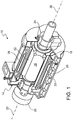
- a rotating superconducting machine 10 includes a rotor assembly 12 mounted within a stator assembly 14.
- Rotor assembly 12 includes rotor coils 16 formed of a high-temperature superconductor (HTS), a torque transfer system (not shown), and an electromagnetic (EM) shield 18.
- HTS high-temperature superconductor
- EM electromagnetic
- rotor coils 16 include several HTS sub-coils formed in a racetrack configuration but other configurations are also possible.
- U.S. Patent No. 6,509,819 discusses exemplary rotor coil configurations in more detail.
- Electromagnetic shield 18 consists of a conductive, non-magnetic material that shields rotor coils 16 by attenuating asynchronous fields produced by the stator currents.
- a brushless exciter 20, the current source for rotor coils 16, consists of a transformer and associated electronics to condition and control the power for the rotor coils.
- Rotor coils 16 are conduction cooled through a rotor support structure with gaseous helium, which circulates inside machine 10 to cool the HTS rotor coils.
- the inward and outward flow of the gaseous helium to rotor assembly 12 passes through the coaxial helium transfer coupling 22, a stationary to rotating union.
- Bearings 24 support rotor assembly 12 within stator assembly 14.
- Stator assembly 14 includes stator coils 26, a back iron 28, and a housing 30. Stacks of stator coils 26 are mounted between a stator support tube or bore tube 32 and back iron 28 as will be discussed in more detail below. Back iron 28 surrounds stator coils 26 providing a low reluctance path for the magnetic field and acting as a flux shield for the surrounding area. Back iron 28 is typically made of steel (e.g., low carbon steel) but can also be made of other materials (e.g., light-weight composite materials). Stator housing 30 supports the stator components as well as bearings 24 that orient the rotor shaft to the stator.
- stator assembly 14 of rotating superconducting machine 10 includes non-magnetic supports 34 for supporting stator coils 26.
- Non-magnetic supports 34 are used, rather than the iron slots typically found in conventional machines, due to the high flux densities produced by the superconductor coils 16.
- supports 34 preferably have low electrical conductivity to prevent excessive eddy current losses.
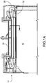
- Non-magnetic supports 34 are mounted on an inner surface 36 of back iron 28 extend parallel to an axis 38 of stator assembly 14.
- Each support 34 includes a primary base 40 and at least two primary support members 42 with dovetail-like members 41 formed as surface features extending from primary base 40 to engage slots 50 defined by inner surface 36 of back iron 28.
- Primary support members 42 extending radially inward from the primary base towards axis 38 of stator assembly 14. As is discussed in more detail below, primary support members 42 extend radially inward from primary base 40 for a first height h between about 35 percent and about 65 percent of a overall height H of stator coils 26 that supports 34 are configured to receive which facilitates manufacture of stator assembly 14.
- each support 34 also includes a secondary support assembly 44 constructed of a fiber-aligned composite which constitutes a secondary base 46 and two secondary support members 48.
- Secondary support members 48 engage primary support members 42 to define a cavity receiving stator coils 26 between primary support members 42 as well as between primary bases 40 and axis 38 of stator assembly 14.
- Secondary base 40 contacts and is supported by bore tube 32 which is located co-axially with back iron 28.
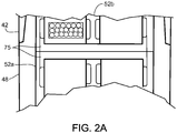
- stator assembly 14 also includes sheet-form inserts 52a, 52b located adjacent stator coils 26 and configured to define coolant channels 54 between the stator coils and the inserts. Having supports 34 that are separate from inserts 52a, 52b provides improved support for stator coils 26 by allowing the combination of relatively stiff supports providing structural stability with resilient inserts providing frictional engagement with the stator coils. Inserts 52a, 52b are formed of a resilient material such as, for example, fiberglass plastic laminate and are sized such that the inserts engage outer surfaces of stator coils 26 in a frictional press fit. Such inserts can also be used in conjunction with other stator assemblies (e.g., stator assemblies with individual primary support members directly attached to the back irons of the stator assemblies).
- stator assemblies e.g., stator assemblies with individual primary support members directly attached to the back irons of the stator assemblies.
- stator assembly includes both outer inserts 52a and inner inserts 52b.
- Each outer insert 52a is located between a stator coil 26 and an adjacent support 34 and are formed with a first broad face 56 and a second broad face 58.
- First broad face 56 has a non-planar surface and second broad face 58 that is substantially flat to conform with surfaces of primary and secondary support members 42, 48.
- Each inner insert 52b is located between adjacent stator coils 26 and both opposing broad faces have non-planar surfaces.
- stator assembly 14 include other inserts such as, for example, ripple springs 53 with opposing faces having matching sinusoidal surfaces located between stator coils 26 and supports 34.
- ripple springs can be used in place of inserts 52a (e.g., disposed between supports 34 and coils 26 with grooves associated with the sinusoidal surfaces oriented substantially parallel to support axis 59 to form coolant channels).
- ripple springs can be used in addition to inserts 52a (e.g., disposed between supports 34 and inserts 52a with grooves associated with the sinusoidal surfaces oriented substantially perpendicular to coolant channels 54 to help fix the position of the inserts relative to the supports and to limit coolant flow between the supports and inserts).
- each stator coil 26 includes multiple Litz wire bundles 55 with a supporting material 57 (e.g., G10 fiberglass composite) providing the coil's overall structural framework as well as separating the individual wire bundles.
- a supporting material 57 e.g., G10 fiberglass composite
- FIG. 2 only shows internal structure for a single exemplary stator coil 26.
- the supporting material 57 extending between wire bundles 55 is more rigid than adjacent portions of coils 26 where the wire bundles are present.
- supporting material 57 e.g., insulation with appropriate structural stability
- Inserts 52a, 52b are configured to align laterally extending portions 62 of the inserts with bridges 57 between wire bundles 55. This alignment supports inserts 52 and help maintain the coolant channels 54.
- support 34 as formed by primary base 40, primary support members 42, secondary base 46 and secondary support members 48 provides phase to phase and phase to ground insulation.
- U-pieces 75 e.g., mica-filled U-pieces
- a dielectric fluid permeating the interior stator spaces of stator assembly 14 e.g., both coolant channels 54 and/or other voids within stator assembly 14
- support 34, inserts 52a, 52b, and U-pieces 75 constitutes a ground and phase-to-phase insulation system as well as being used as a coolant fluid.
- This integrated system allows the dielectric fluid to flow close to the stator coils 26 without thick ground wall insulation and can substantially improve heat transfer between the dielectric fluid flowing in the channels and the conductive wire bundles 55.
- supports 34, 44 are manufactured of fiber aligned composites to provide additional structural stability.
- the composite forming primary base 40 and primary support members 42 includes fibers 77 that are aligned substantially within planes transverse to a support axis 59 (e.g., extending substantially within the U-shape of a cross-section of the primary base and the primary support members).
- Primary base 40 and primary support members 42 can also include fibers that are aligned substantially parallel to support axis 59 (e.g. extending into the plane of the cross-section).
- Members 41 extending from primary base 40 can include randomly oriented fibers.
- Secondary support assembly 44 can include fibers aligned in a similar fashion.
- Coolant channels 54 extend adjacent stator coils 26 and substantially parallel to axis 38 of stator assembly 14 and provide direct contact between a liquid coolant and stator coils 26.
- the associated efficiency of heat transfer is important because the physical size of superconducting machine 10 is smaller than that of a conventional machine of the same rating with a reduced surface area for cooling.
- coolant channels 54 are configured with a main portion 60 with a depth d of less than about 0.1 inch.
- Inserts 52 can have a thickness t less than 0.25 inch because coolant channels 54 are shallow.
- at least some of the coolant channels can have depth to width ratio of less than about 1 to 5 to provide good heat transfer efficiency (e.g., a coolant channel with a depth of 0.075 inch and a width 0.5 inch).
- back iron 28 is provided as a substantially cylindrical annular structure having an inner surface and an axis.
- First portions of supports 34 including primary base 40 and primary support members 42 are attached to back iron 28 by engaging slots 50 defined by inner surface 36 of the back iron with surface features 41 extending from the primary base.
- An epoxy is used to form local bonds between primary bases 40, primary support members 42, and back iron 28.
- the epoxy is cured at room temperature.
- these local bonds can be formed by heating sections of stator assembly 14 with heaters to cure the epoxy. Because this bonding operation is performed before the stator coils are installed, the bonds can be inspected prior to coil installation.
- Stator coils 26 positioned in stacks are then loaded into a recess defined by primary base 40 and primary support members 42 with each stack extending radially inward from the primary base of support 34 towards axis 38 of stator assembly 14.
- stator coils 26 are diamond coils with portions in two separated supports 34 with a portion of each coil sharing a support recess with a portion of another coil in an overlapping configuration.
- a first throw of stator coils 26 are loaded into stator assembly 14 and temporarily lashed to supports 34. As the rest of the stator coils 26 are installed, a final end-turn lashing is made, holding the stator coils in position.
- the lifting of the first throw to load the final throw is facilitated by the configuration of primary support members 42 with a height h that is between about 35 percent and 65 percent of the overall height H of the combined coils. Special tooling for locating and holding the top and bottom legs of the coils in position is used while the winding process proceeds.
- Secondary support assemblies 44 are then installed with secondary support members 48 engaging primary support members 42.
- sheet form inserts 52 are installed adjacent stacks of stator coils 26 at various times during this process depending on the location of particular inserts relative to the stator coils and supports 34.
- This method of assembly provides a stator assembly 14 with double-U supports 34 that provide good cooling and mechanical support.
- supports 34 were made of a high-modulus fiber aligned composite selected because the high modulus provides stiffness in bending.
- These high stiffness composites are made by applying techniques similar to those used for aircraft structures, employing a mixture of high strength fiberglass cloths. The composite is hand-layed up, vacuum bagged, and autoclave cured. The result is a composite with a modulus of about 34500 MPa (5 Mpsi). The added stiffness reduces operating deflections.
- using composite supports allows the use of higher flux densities through the field windings and, thus, a higher gap shear stress (e.g., above 10 pounds per square inch).
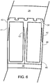
- FIG. 5 a finite element analysis (numerical simulation) of the response of a stator assembly as described above to a stress loading with peak values of 95 MPa at distributed points along the inner surface of stator assembly 14.
- the event conditions represent anticipated loadings that would occur during a 9-phase fault (i.e., when the worst case scenario of all nine leads of a nine phase system short-circuiting together).
- FIG. 5 shows a portion of the stator assembly including multiple interlocked supports 34.
- the shading qualitatively indicates the distribution of deflection predicted by this analysis in different parts of the stator assembly ranging from a maximum predicted deflection of about 0.6 millimeters along the bore tube (not shown-along the inner circumference) to less than about 0.06 millimeters along the back iron (not shown - along the outer circumference).
- the engagement between adjacent supports 34 is predicted to distribute the imposed stress resulting in a lower maximum point deflection and, consequently, a lower likelihood of structural failure.
- each support could have three or more primary support members 42 extending primary support base 40.
Landscapes
- Engineering & Computer Science (AREA)
- Power Engineering (AREA)
- Iron Core Of Rotating Electric Machines (AREA)
- Superconductive Dynamoelectric Machines (AREA)
- Insulation, Fastening Of Motor, Generator Windings (AREA)
- Manufacture Of Motors, Generators (AREA)
Claims (14)
- Stator (14) für eine supraleitende elektrische Luftkern-Maschine (10), wobei der Stator (14) Folgendes umfasst:einen magnetischen Rückschluss (28), der eine zylindrische ringförmige Struktur mit einer inneren Fläche (36) und einer Achse (38) aufweist;mehrere Träger (34), die aus nicht magnetischem Material hergestellt sind, wobei sich jeder Träger (34) parallel zu der Achse (38) der ringförmigen Struktur entlang der inneren Fläche (36) der ringförmigen Struktur erstreckt, wobei jeder Träger (34) eine primäre Basis (40) und mindestens zwei primäre Trägerelemente (42) aufweist, wobei die primäre Basis mit der inneren Fläche (36) des magnetischen Rückschlusses (28) übereinstimmt, wobei sich die primären Trägerelemente (42) von der primären Basis (40) radial nach innen hin zu der Achse (38) der ringförmigen Struktur erstrecken; undeine Statorwicklung (26), die zwischen den mindestens zwei primären Trägerelementen (42) und zwischen der primären Basis (40) des Trägers (34) und der Achse (38) der ringförmigen Struktur positioniert ist,wobei jeder Träger (34) ferner eine sekundäre Trägeranordnung (44) aufweist, wobei die sekundäre Trägeranordnung (44) eine sekundäre Basis (46) und mindestens zwei sekundäre Trägerelemente (48) aufweist,dadurch gekennzeichnet, dassdie sekundären Trägerelemente (48) mit den primären Trägerelementen (42) in Eingriff kommen, um einen Hohlraum zu definieren, der die Statorwicklung (26) aufnimmt.
- Stator (14) nach Anspruch 1, wobei die primäre Basis (40) und primären Trägerelemente (42) einen geformten Verbund mit ausgerichteten Fasern umfassen.
- Stator (14) nach Anspruch 1, wobei die sekundäre Basis (46) und sekundären Trägerelemente (48) einen geformten Verbund mit ausgerichteten Fasern umfassen.
- Stator (14) nach Anspruch 1, wobei sich die primären Trägerelemente (42) von der primären Basis (40) um einen Abstand (h) zwischen 35 Prozent und 65 Prozent von einer Höhe (H) der Statorwicklung (26) radial nach innen erstrecken.
- Stator (14) nach Anspruch 1, ferner umfassend einen blechförmigen Einsatz (52a, 52b), der sich benachbart zu der Statorwicklung (26) befindet, wobei der Einsatz (52a, 52b) und die Statorwicklung (26) Kühlmittelkanäle (54) definieren.
- Stator (14) nach Anspruch 5, ferner umfassend ein dielektrisches Kühlfluid in den Kühlmittelkanälen.
- Stator (14) nach Anspruch 5, wobei der Einsatz (52a, 52b) ein blechförmiges elastisches Element umfasst, das eine erste Breitfläche (56) mit einer nicht planaren Fläche aufweist.
- Stator (14) nach Anspruch 7, wobei sich der Einsatz (52a, 52b) zwischen der sekundären Trägeranordnung (44) und der Statorwicklung (26) befindet.
- Stator (14) nach Anspruch 5, wobei die Statorwicklung (26) erste Abschnitte (57) und zweite Abschnitte (55) aufweist, wobei die ersten Abschnitte (57) starrer sind als die zweiten Abschnitte (55); und
wobei ein Kontakt zwischen dem Einsatz (52a, 52b) und der Statorwicklung (26) auf einer Fläche der ersten Abschnitte (57) der Statorwicklung (26) ist. - Stator (14) nach Anspruch 9, wobei die ersten Abschnitte (57) der Statorwicklung ein Trägermaterial umfassen, das sich zwischen gegenüberliegenden Seiten der Statorwicklung (26) erstreckt.
- Stator (14) nach Anspruch 10, wobei das Trägermaterial einen Glasfaserverbund umfasst.
- Stator (14) nach Anspruch 10, wobei die Statorwicklung (26) eine Spule mit mehreren Drahtbündeln (55) umfasst, wobei die Drahtbündel (55) voneinander durch das Trägermaterial (57) getrennt sind.
- Stator (14) nach Anspruch 1, wobei sich mindestens drei primäre Trägerelemente (34) von der primären Trägerbasis (40) erstrecken.
- Stator (14) nach Anspruch 1, wobei die sekundäre Basis (46) eine zylindrische ringförmige Bohrungsröhre (32) berührt, die sich koaxial mit dem magnetischen Rückschluss (28) befindet.
Applications Claiming Priority (2)
| Application Number | Priority Date | Filing Date | Title |
|---|---|---|---|
| US11/516,970 US7786645B2 (en) | 2006-09-07 | 2006-09-07 | Superconducting machine stator |
| PCT/US2007/077864 WO2008031019A2 (en) | 2006-09-07 | 2007-09-07 | Stator winding support for a superconducting machine |
Publications (2)
| Publication Number | Publication Date |
|---|---|
| EP2059992A2 EP2059992A2 (de) | 2009-05-20 |
| EP2059992B1 true EP2059992B1 (de) | 2019-11-06 |
Family
ID=38920514
Family Applications (1)
| Application Number | Title | Priority Date | Filing Date |
|---|---|---|---|
| EP07814752.7A Active EP2059992B1 (de) | 2006-09-07 | 2007-09-07 | Statorwicklungsträger für eine supraleitende maschine |
Country Status (7)
| Country | Link |
|---|---|
| US (1) | US7786645B2 (de) |
| EP (1) | EP2059992B1 (de) |
| JP (1) | JP5101619B2 (de) |
| KR (1) | KR101090944B1 (de) |
| AU (1) | AU2007292252B2 (de) |
| CA (1) | CA2660731C (de) |
| WO (1) | WO2008031019A2 (de) |
Families Citing this family (17)
| Publication number | Priority date | Publication date | Assignee | Title |
|---|---|---|---|---|
| WO2008136044A1 (ja) * | 2007-04-18 | 2008-11-13 | Kabushiki Kaisha Toshiba | 回転電機 |
| US7994679B2 (en) | 2009-02-04 | 2011-08-09 | Teco-Westinghouse Motor Company | Small air gap air core stator |
| JP5471285B2 (ja) * | 2009-10-20 | 2014-04-16 | 住友電気工業株式会社 | ステータ、ロータ、および超電導機器 |
| US8664809B2 (en) * | 2011-03-15 | 2014-03-04 | Siemens Energy, Inc. | Apparatus to support superconducting windings in a rotor of an electromotive machine |
| US8558422B2 (en) | 2011-03-31 | 2013-10-15 | Caterpillar Inc. | Uniform contained cooling for stator |
| US20140183988A1 (en) * | 2012-12-31 | 2014-07-03 | Teco-Westinghouse Motor Company | Assemblies For Cooling Electric Machines |
| US9509194B2 (en) | 2014-01-07 | 2016-11-29 | Ge Aviation Systems Llc | Generator assembly |
| US9543814B2 (en) * | 2014-01-07 | 2017-01-10 | Ge Aviation Systems Llc | Method of making a heat transfer element for an electric machine |
| US10601299B2 (en) * | 2017-09-07 | 2020-03-24 | American Superconductor Corporation | High temperature superconductor generator with increased rotational inertia |
| US11606017B2 (en) | 2018-06-27 | 2023-03-14 | General Electric Company | Wind turbine having superconducting generator and armature for use in the superconducting generator |
| JP2020137371A (ja) * | 2019-02-25 | 2020-08-31 | 株式会社デンソー | 電機子及び回転電機 |
| US12166384B2 (en) * | 2019-03-19 | 2024-12-10 | Magna powertrain gmbh & co kg | High performance electromagnetic machine and cooling system |
| FR3104341A1 (fr) * | 2019-12-04 | 2021-06-11 | Safran | Machine électrique à barrière de flux à induit et inducteur supraconducteurs |
| DE102020126184B4 (de) * | 2020-10-07 | 2022-06-09 | Schaeffler Technologies AG & Co. KG | Elektrische Maschine |
| EP4024672A1 (de) | 2020-12-30 | 2022-07-06 | General Electric Renovables España S.L. | Armaturensegment, armatur und verfahren zu deren zusammenbau |
| US11757335B2 (en) | 2021-04-06 | 2023-09-12 | Hamilton Sundstrand Corporation | Cooling channels in a high-density motor |
| WO2023004012A2 (en) * | 2021-07-21 | 2023-01-26 | Georgia Tech Research Corporation | Evaporative embedded thermal management of electric motor |
Family Cites Families (12)
| Publication number | Priority date | Publication date | Assignee | Title |
|---|---|---|---|---|
| US3334255A (en) * | 1965-02-19 | 1967-08-01 | Robert W Peters | Electric motor |
| US3735169A (en) * | 1971-04-04 | 1973-05-22 | Gen Electric | Channel,shaped,laminated,high temperature slot wedge for dynamoelectric machines |
| US3943392A (en) * | 1974-11-27 | 1976-03-09 | Allis-Chalmers Corporation | Combination slot liner and retainer for dynamoelectric machine conductor bars |
| SE508318C2 (sv) * | 1993-05-26 | 1998-09-21 | Atlas Copco Tools Ab | Stator för en elektrisk maskin |
| US5698917A (en) * | 1995-09-25 | 1997-12-16 | Glacier Rpb Inc. | Electromagnetic bearing with a stationary armature canning arrangement |
| JPH11122855A (ja) | 1997-10-17 | 1999-04-30 | Toshiba Corp | ステータ用コイルボビンと電動機 |
| JP3624825B2 (ja) * | 2000-12-14 | 2005-03-02 | 日産自動車株式会社 | 回転電機および回転電機の製造方法 |
| ATE421792T1 (de) | 2001-04-20 | 2009-02-15 | Converteam Ltd | Kühlung von luftspaltelektrischermaschinewicklungen |
| WO2003021746A1 (en) | 2001-08-31 | 2003-03-13 | Mitsubishi Denki Kabushiki Kaisha | Bobbin for motor |
| JP2004017125A (ja) | 2002-06-19 | 2004-01-22 | Omc Kk | 冷陰極管とファーネスとの接続方法とその接続構造 |
| JP3906124B2 (ja) | 2002-07-25 | 2007-04-18 | 本田技研工業株式会社 | 回転機の電機子コイル |
| JP4001040B2 (ja) * | 2003-03-28 | 2007-10-31 | 株式会社デンソー | 回転電機の固定子 |
-
2006
- 2006-09-07 US US11/516,970 patent/US7786645B2/en active Active
-
2007
- 2007-09-07 JP JP2009526953A patent/JP5101619B2/ja active Active
- 2007-09-07 CA CA2660731A patent/CA2660731C/en not_active Expired - Fee Related
- 2007-09-07 AU AU2007292252A patent/AU2007292252B2/en not_active Ceased
- 2007-09-07 WO PCT/US2007/077864 patent/WO2008031019A2/en not_active Ceased
- 2007-09-07 KR KR1020097006736A patent/KR101090944B1/ko active Active
- 2007-09-07 EP EP07814752.7A patent/EP2059992B1/de active Active
Non-Patent Citations (1)
| Title |
|---|
| None * |
Also Published As
| Publication number | Publication date |
|---|---|
| CA2660731A1 (en) | 2008-03-13 |
| JP5101619B2 (ja) | 2012-12-19 |
| US20080061637A1 (en) | 2008-03-13 |
| CA2660731C (en) | 2014-07-22 |
| KR20090085574A (ko) | 2009-08-07 |
| US7786645B2 (en) | 2010-08-31 |
| JP2010502171A (ja) | 2010-01-21 |
| EP2059992A2 (de) | 2009-05-20 |
| AU2007292252B2 (en) | 2010-12-16 |
| WO2008031019A3 (en) | 2008-05-02 |
| KR101090944B1 (ko) | 2011-12-08 |
| AU2007292252A1 (en) | 2008-03-13 |
| WO2008031019A2 (en) | 2008-03-13 |
Similar Documents
| Publication | Publication Date | Title |
|---|---|---|
| EP2059992B1 (de) | Statorwicklungsträger für eine supraleitende maschine | |
| Reddy et al. | Comparison of interior and surface PM machines equipped with fractional-slot concentrated windings for hybrid traction applications | |
| US7489060B2 (en) | Superconducting rotating machines with stationary field coils | |
| US7211919B2 (en) | Thermally-conductive stator support structure | |
| US4330726A (en) | Air-gap winding stator construction for dynamoelectric machine | |
| EP3723242B1 (de) | Synchrone elektrische reluktanzmaschine mit hülsenrotor | |
| Mitcham et al. | Favourable slot and pole number combinations for fault-tolerant PM machines | |
| US7119644B2 (en) | Mounting structure for superconducting windings | |
| US11496025B2 (en) | Stator for an electric rotating machine | |
| US4278905A (en) | Apparatus for supporting a stator winding in a superconductive generator | |
| EL-Refaie et al. | High-power-density fault-tolerant PM generator for safety-critical applications | |
| US20030102759A1 (en) | Hybrid machines and methods of fabrication | |
| US20230361637A1 (en) | Electric machines with enhanced electromagnetic interaction | |
| KR100761432B1 (ko) | 회전자 어셈블리 | |
| Swanke et al. | Modular fault-tolerant machine design with improved electromagnetic isolation for urban air mobility (UAM) aircraft | |
| Ibrahim et al. | A novel toroidal permanent magnet motor structure with high torque density and enhanced cooling | |
| US20030030339A1 (en) | Rotating back iron for synchronous motors/generators | |
| US5705869A (en) | Magnetic axial thrust bearings fabricated on individual stator segments | |
| Calfo et al. | High‐Speed Generators for Power‐Dense, Medium‐Power, Gas Turbine Generator Sets | |
| Li et al. | Comparison of High Power Density Permanent Magnet Machines with Different Slot/Pole Number Combinations | |
| CA1170304A (en) | Air-gap winding stator construction for dynamoelectric machine |
Legal Events
| Date | Code | Title | Description |
|---|---|---|---|
| PUAI | Public reference made under article 153(3) epc to a published international application that has entered the european phase |
Free format text: ORIGINAL CODE: 0009012 |
|
| 17P | Request for examination filed |
Effective date: 20090313 |
|
| AK | Designated contracting states |
Kind code of ref document: A2 Designated state(s): DE FR GB IT |
|
| AX | Request for extension of the european patent |
Extension state: AL BA HR MK RS |
|
| RAP1 | Party data changed (applicant data changed or rights of an application transferred) |
Owner name: AMERICAN SUPERCONDUCTOR CORPORATION |
|
| DAX | Request for extension of the european patent (deleted) | ||
| 17Q | First examination report despatched |
Effective date: 20100819 |
|
| GRAP | Despatch of communication of intention to grant a patent |
Free format text: ORIGINAL CODE: EPIDOSNIGR1 |
|
| STAA | Information on the status of an ep patent application or granted ep patent |
Free format text: STATUS: GRANT OF PATENT IS INTENDED |
|
| RIC1 | Information provided on ipc code assigned before grant |
Ipc: H02K 3/24 20060101ALI20190329BHEP Ipc: H02K 3/47 20060101AFI20190329BHEP |
|
| INTG | Intention to grant announced |
Effective date: 20190417 |
|
| GRAS | Grant fee paid |
Free format text: ORIGINAL CODE: EPIDOSNIGR3 |
|
| GRAA | (expected) grant |
Free format text: ORIGINAL CODE: 0009210 |
|
| STAA | Information on the status of an ep patent application or granted ep patent |
Free format text: STATUS: THE PATENT HAS BEEN GRANTED |
|
| AK | Designated contracting states |
Kind code of ref document: B1 Designated state(s): DE FR GB IT |
|
| REG | Reference to a national code |
Ref country code: GB Ref legal event code: FG4D |
|
| REG | Reference to a national code |
Ref country code: DE Ref legal event code: R096 Ref document number: 602007059466 Country of ref document: DE |
|
| REG | Reference to a national code |
Ref country code: DE Ref legal event code: R081 Ref document number: 602007059466 Country of ref document: DE Owner name: AMERICAN SUPERCONDUCTOR CORPORATION, AYER, US Free format text: FORMER OWNER: AMERICAN SUPERCONDUCTOR CORP., DEVENS, MASS., US |
|
| RAP2 | Party data changed (patent owner data changed or rights of a patent transferred) |
Owner name: AMERICAN SUPERCONDUCTOR CORPORATION |
|
| RAP2 | Party data changed (patent owner data changed or rights of a patent transferred) |
Owner name: AMERICAN SUPERCONDUCTOR CORPORATION |
|
| REG | Reference to a national code |
Ref country code: DE Ref legal event code: R097 Ref document number: 602007059466 Country of ref document: DE |
|
| PLBE | No opposition filed within time limit |
Free format text: ORIGINAL CODE: 0009261 |
|
| STAA | Information on the status of an ep patent application or granted ep patent |
Free format text: STATUS: NO OPPOSITION FILED WITHIN TIME LIMIT |
|
| 26N | No opposition filed |
Effective date: 20200807 |
|
| P01 | Opt-out of the competence of the unified patent court (upc) registered |
Effective date: 20230810 |
|
| PGFP | Annual fee paid to national office [announced via postgrant information from national office to epo] |
Ref country code: DE Payment date: 20250929 Year of fee payment: 19 |
|
| PGFP | Annual fee paid to national office [announced via postgrant information from national office to epo] |
Ref country code: IT Payment date: 20250919 Year of fee payment: 19 |
|
| PGFP | Annual fee paid to national office [announced via postgrant information from national office to epo] |
Ref country code: GB Payment date: 20250929 Year of fee payment: 19 |
|
| PGFP | Annual fee paid to national office [announced via postgrant information from national office to epo] |
Ref country code: FR Payment date: 20250925 Year of fee payment: 19 |