EP2059904B1 - Computerized imaging method for a three - dimensional reconstruction from two - dimensional radiological images;implementation device - Google Patents
Computerized imaging method for a three - dimensional reconstruction from two - dimensional radiological images;implementation device Download PDFInfo
- Publication number
- EP2059904B1 EP2059904B1 EP07823657A EP07823657A EP2059904B1 EP 2059904 B1 EP2059904 B1 EP 2059904B1 EP 07823657 A EP07823657 A EP 07823657A EP 07823657 A EP07823657 A EP 07823657A EP 2059904 B1 EP2059904 B1 EP 2059904B1
- Authority
- EP
- European Patent Office
- Prior art keywords
- images
- subject
- radiological
- radiological images
- dimensional
- Prior art date
- Legal status (The legal status is an assumption and is not a legal conclusion. Google has not performed a legal analysis and makes no representation as to the accuracy of the status listed.)
- Not-in-force
Links
Images


Classifications
-
- G—PHYSICS
- G06—COMPUTING; CALCULATING OR COUNTING
- G06T—IMAGE DATA PROCESSING OR GENERATION, IN GENERAL
- G06T7/00—Image analysis
- G06T7/80—Analysis of captured images to determine intrinsic or extrinsic camera parameters, i.e. camera calibration
- G06T7/85—Stereo camera calibration
-
- G—PHYSICS
- G06—COMPUTING; CALCULATING OR COUNTING
- G06T—IMAGE DATA PROCESSING OR GENERATION, IN GENERAL
- G06T2207/00—Indexing scheme for image analysis or image enhancement
- G06T2207/10—Image acquisition modality
- G06T2207/10028—Range image; Depth image; 3D point clouds
-
- G—PHYSICS
- G06—COMPUTING; CALCULATING OR COUNTING
- G06T—IMAGE DATA PROCESSING OR GENERATION, IN GENERAL
- G06T2207/00—Indexing scheme for image analysis or image enhancement
- G06T2207/10—Image acquisition modality
- G06T2207/10116—X-ray image
-
- G—PHYSICS
- G06—COMPUTING; CALCULATING OR COUNTING
- G06T—IMAGE DATA PROCESSING OR GENERATION, IN GENERAL
- G06T2207/00—Indexing scheme for image analysis or image enhancement
- G06T2207/30—Subject of image; Context of image processing
- G06T2207/30004—Biomedical image processing
-
- G—PHYSICS
- G06—COMPUTING; CALCULATING OR COUNTING
- G06T—IMAGE DATA PROCESSING OR GENERATION, IN GENERAL
- G06T2207/00—Indexing scheme for image analysis or image enhancement
- G06T2207/30—Subject of image; Context of image processing
- G06T2207/30004—Biomedical image processing
- G06T2207/30008—Bone
- G06T2207/30012—Spine; Backbone
Definitions
- the present invention relates to a computer-aided X-ray image processing method for three-dimensional reconstruction from two-dimensional images and to an implementation device. It has applications in the field of radiology.
- X-ray imaging systems are known, such as scanner or MRI systems, which make it possible, after reconstruction, to obtain three-dimensional images of all the parts of a patient, both of the bones and of the surrounding tissues.
- These systems like the CT scanner, allow to obtain radiological images of great fineness in the three dimensions, but are nevertheless of a very important cost and of a relatively heavy implementation, without counting the important dose of radiation. received by the patient.
- CT scanner X-ray imaging systems
- these systems like the CT scanner, allow to obtain radiological images of great fineness in the three dimensions, but are nevertheless of a very important cost and of a relatively heavy implementation, without counting the important dose of radiation. received by the patient.
- certain types of examination especially those concerning bone structures which, among the body elements, are those that are best visualized in radiology, there is no need for such fineness. This is particularly the case for posture problems, and all problems related to the spine in general.
- the present invention proposes the use of a conventional radiological material and implements a determination of the displacements and deformations of the radiographed subject between two acquisitions in different orientations so as to correct the deformations directly on the interpretation of the radiological data.
- Such an approach differs from the previous solutions insofar as it does not seek to constrain the movements and to avoid the deformations of the object between the two acquisitions.
- the invention relates to a computerized radiological imaging method for three-dimensional reconstruction from two-dimensional radiological images of an area of interest, wherein two two-dimensional radiographic images of a subject are acquired by a coupled radiography means to a computer equipment, the radiological images being taken successively according to different incidences relative to the subject, the subject having been able to deform between the acquisitions of radiological images.
- the invention also relates to a computerized imaging device for three-dimensional reconstruction from two-dimensional radiological images of an area of interest, in which two two-dimensional radiographic images of a subject are acquired by radiographic means coupled to a computer equipment, the radiological images being taken successively according to different incidences with respect to the subject, the subject having been able to deform between two successive acquisitions, the device comprising means allowing the execution of the method according to one or more of the characteristics previously listed .
- the method of the invention therefore makes it possible to determine a 3D space derived from radiographic information, from non-stereo-corresponding radiographic recording conditions. It only requires one conventional radiographic source to perform the corresponding stereo reconstruction. It does not require precise knowledge of the incidence between the two radiographic shots to allow the corresponding stereo reconstruction. In addition, it supports the deformations of the subject between the different radiographic shots without altering the correspondence between the X-rays for the 3D reconstruction.
- the method is relatively simple to implement to access the 3D exploitation of conventional radiographs unlike other methods that involve bulky equipment and a heavy protocol to implement.
- a computer equipment comprising means for executing a computer program on data, input / output means, in particular for the visualization and / or the printing of results, as well as an imager (real time or not), for capturing on the one hand radiological images in the form of digital radiological data and, on the other hand, images 3D of the surface of a radiographed subject also in the form of digital surface data.
- the capture of the 3D images is performed by a 3D surface sensor which is a surface sensor, for example of the Moiré fringe type.
- the processed data are generally in matrix form (2D or 3D as the case may be) in the memories of the computer equipment.
- the computer equipment is programmed according to an algorithm in a programming language.
- the method uses radiological images and surface 3D images of a radiographed subject together. At least two markers are visible on the subject visible to both the surface sensor and the radiographic imager. The marks are positioned on the surface of the subject in areas related to the structure to be analyzed, the spine in this case. Thus, one can have three markers along the spine, for example a marker towards the top of the spine, a mark towards the bottom of the spine and a third graduated mark of the type visible radio strip, out of the spine which allows to have a scale on the final views.
- a surface sensor 4 producing three-dimensional images of the subject's surface, is used in parallel with the acquisition of two-dimensional X-ray images by means of an X-ray source 2 at a first incidence 3 and according to a second incidence 3 '.
- a 3D surface image associated with a radiological image at said incidence.
- Skin markers visible on 3D surface images and also radiopaque and thus visible on 2D radiographs, are placed on the X-rayed subject.
- the 3D surface sensor records the area of interest that is simultaneously (or almost simultaneously) radiographed for two different incidences. These two incidences are obtained either as a result of the displacement (rotation in this case) of the x-rayed subject, or as a result of the displacements of the radio source X and the surface sensor.
- first surface image of the body of the subject according to a first sensor incidence relative to the subject for example oblique from the back to the right
- second surface image of the body of the subject according to a second incidence of sensor relative to the subject for example oblique of back to the left
- first radiological image according to a first radio incidence relative to the subject for example of profile
- second radiological image according to a second radio incidence relative to the subject eg back
- the first surface and radiological images are made at the same moment or almost at the same moment so that the subject does not have time to move or to deform.
- the second surface and radiological images are made at the same time or almost at the same time so that the subject also does not have time to move or to deform.
- the subject will have been rotated with respect to the source X and the surface sensor, or the surface sensor and the source X rotated relative to the subject.
- the marks are preferably arranged according to the area of interest.
- markers each of different shape or having a specific sign visible in radio and on the surface images, preferably automatically recognizable by the computer equipment
- a calibration of the radiological images with one another is carried out by means of two interdependent operations according to an iterative process: a registration 6 and a comparison 7.
- the first operation is a registration 6 between the surface image 9 (surface acquisition by the surface sensor 4) and the corresponding radiological image 8 (made at the same / almost same instant), under the first radio incidence, and a resetting 6 'between the surface image 9' (surface acquisition by the surface sensor 4) and the corresponding radiological image 8 'under the second radio incidence.
- This operation is based on the surface markings also visible on the radiological image. From these marks expressed simultaneously in the space of the surface sensor and in the radiography spaces, the resetting operation makes it possible to position the radiographs with respect to the surface images. It may be noted that a resetting operation is implemented in the application PCT / FR03 / 03943 .
- the second operation consists of a comparison 7 between two surface images taken in relation to different sensor bearings in order to extract information from a possible distortion of the subject between the two acquisitions. and, on the other hand, extracting the information from the relative positioning (difference between the first and second sensor bearings) of the surface sensor between the two surface image shots.
- X-rays are deformed in the opposite direction to any deformations evaluated during the comparison operation of the surface images.
- Corrected X-ray means the modification of the interpretation of X-rays taking into account the possible movements of the subject between a radiography in strict stereographic conditions and the radiography actually taken. From these corrected X-rays (deformed in inverse), the new coordinates of the surface markers are calculated in the surface reference system (a sort of transposition of the marks from the internal / radio space to the external space is carried out. /of surface).
- a gradient of deformation between the surface images is determined (block 19), this gradient is applied (block 21) to the radiographs, and the new coordinates of the surface markers are calculated (block 22) from these radiographs. . Then, compare (block 23) these new coordinates to those corresponding to the initial position of the marks (ie the 3D position of the marks on the acquired surface image) with a difference calculation. This comparison makes it possible to fix a criterion for stopping the iteration. When the difference becomes less than or equal to a stopping threshold, then the radiographs on which the gradient has been applied are calibrated (block 24).
- first incidence calculation phase which comprises two times, a first time with a resetting operation and a second time with a comparison operation.
- the comparison operation allows the determination (block 17) of the relative positioning of the two surface acquisitions.
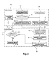
- the positioning is obtained from the cutaneous marks 26 seen under two different impacts on 3D surface images. Considering that the subject was not deformed between the two shots and knowing the position of these landmarks for the two surface acquisitions, the two acquisitions of surface images are then repositioned in the same frame as represented Figure 7 . This positioning therefore assumes that possible deformation of the subject between shots only slightly affects the position of the cutaneous marks. In a more evolved variant, in order to prevent the effects of a possible deformation, the positioning can be carried out taking into account a larger surface area (more numerous markers and / or spread over a larger area) in order to minimize the risks. local errors.
- the wavy lines 27 represent the surface of the subject as obtained with a Moiré fringe type sensor.
- the two radiological images are repositioned in the same 3D reference frame, thus making it possible to estimate the possible deformations of the x-rayed subject.
- a first step from the two acquisitions of 3D surface images, the deformation is evaluated by implementing a step 19 of determining a deformation gradient.
- This evaluation consists in optimally superimposing the cutaneous marks of the two acquisitions of surface images following the repositioning of the incidence calculation phase 10.
- the 3D deformations that appear on the surface images are quantified, giving priority to the zones of interest, that is, areas close to the internal structures studied.
- a 3D deformation gradient is obtained, that is to say a direction, a direction and an intensity in the space making it possible to pass from a first 3D object to this same 3D object but deformed.
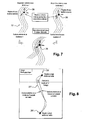
- This deformation gradient is then projected in the radiographic plane of one of the radiographs so as to obtain a 2D strain gradient.
- This 2D deformation gradient is then applied (step 21), in the opposite direction, to the pixels of the radiographic image, that is to say that the interpretation of the pixels of the radiographic image is corrected by taking into account the calculated strain gradient.
- this 2D gradient is applied in the opposite direction to correct the deformations of the X-rayed subject between the two X-ray images so as to simulate a radiography which would verify the non deformation of the subject and thus obtain a stereo-correspondence.
- the surface lines 27 are projected into the radio space to form projected surface lines 27 '. It is thus possible to determine the gradient ⁇ to be applied to the radiological image. Radiopaque markers 26 and 26 'are visible on the radiological image.
- the two radiographs are then taken into account, assuming that there is no deformation between the two radiological images and that the relative incidence is known. It is then necessary to loop back the deformation calculation and incidence calculation phase. Indeed, the X-ray being possibly distorted, the marks taken on it for the calculation of incidence are no longer correct. It is therefore necessary to readjust the incidence calculation taking into account the deformed radio. This readjustment is done through an iterative loop taking over the incidence calculation and the deformation calculation from the new deformed X-rays.
- the X source and the surface sensor can move between acquisitions instead of the subject being moved.
- the surface sensor may be arranged with a shooting direction always at 45 ° to that of the radio source so that, even for lateral and frontal radio impacts, most of the subject's back (and therefore ) on the surface images without the need to move the surface sensor.
- the process can be refined by making more than two acquisitions, thus taking into account more than two radiological images, each associated with its surface image.
Description
La présente invention concerne un procédé de traitement d'images radiologiques, par rayons X, informatisé permettant une reconstruction tridimensionnelle à partir d'images bidimensionnelles ainsi qu'un dispositif de mise en oeuvre. Elle a des applications dans le domaine de la radiologie.The present invention relates to a computer-aided X-ray image processing method for three-dimensional reconstruction from two-dimensional images and to an implementation device. It has applications in the field of radiology.
On connaît des systèmes d'imagerie radiologique, tels que des systèmes scanners ou IRM, qui permettent d'obtenir, après reconstruction, des images tridimensionnelles de toutes les parties d'un patient, aussi bien des os que des tissus environnants. Ces systèmes, comme le tomodensitomètre, permettent d'obtenir des images radiologiques d'une grande finesse dans les trois dimensions, mais sont toutefois d'un coût très important et d'une mise en oeuvre relativement lourde, sans compter la dose importante de rayonnement reçue par le patient. Or, pour certains types d'examen, notamment ceux concernant des structures osseuses qui, parmi les éléments du corps, sont celles qui sont le mieux visualisables en radiologie, il n'y a pas besoin d'une telle finesse. C'est notamment le cas pour les problèmes de posture, et tous les problèmes liés à la colonne vertébrale en général. Il peut être alors intéressant d'utiliser des appareils de radiologie classiques produisant des images en deux dimensions (2D) et de reconstituer des images en trois dimensions (3D) à partir de plusieurs images en deux dimensions prises selon des orientations ou incidences différentes. Avantageusement, ces acquisitions 2D peuvent être faites alors que le patient est en position debout, et ceci contrairement aux dispositifs mettant en oeuvre des procédés de reconstruction 3D de l'art antérieur qui nécessitent que le patient soit couché. Une telle approche permettrait de rendre accessible au plus grand nombre et à un coût raisonnable des examens de ce type. Toutefois, lorsque l'on réalise plusieurs clichés selon des orientations ou incidences différentes, sauf à utiliser plusieurs sources X pour faire des images synchrones, le patient peut s'être déformé, ce qui dégrade la reconstitution 3D.X-ray imaging systems are known, such as scanner or MRI systems, which make it possible, after reconstruction, to obtain three-dimensional images of all the parts of a patient, both of the bones and of the surrounding tissues. These systems, like the CT scanner, allow to obtain radiological images of great fineness in the three dimensions, but are nevertheless of a very important cost and of a relatively heavy implementation, without counting the important dose of radiation. received by the patient. However, for certain types of examination, especially those concerning bone structures which, among the body elements, are those that are best visualized in radiology, there is no need for such fineness. This is particularly the case for posture problems, and all problems related to the spine in general. It may be interesting to use conventional X-ray equipment producing two-dimensional (2D) images and to reconstruct three-dimensional (3D) images from several two-dimensional images taken at different orientations or angles. Advantageously, these 2D acquisitions can be made while the patient is in a standing position, and this in contrast to the devices implementing 3D reconstruction methods of the prior art that require the patient is lying. Such an approach would make such examinations accessible to the greatest number and at a reasonable cost. However, when several pictures are taken according to different orientations or incidences, except to use several X sources to make synchronous images, the patient may have deformed, which degrades the 3D reconstruction.
En effet, pour obtenir une reconstruction 3D, il est nécessaire d'avoir deux vues d'une même zone à examiner sous des incidences différentes. Ces deux vues doivent répondre aux deux critères suivants : D'une part, le patient ne doit pas se déformer entre les deux vues ; et, d'autre part, il doit être possible de remonter à la position relative des sources des deux vues par rapport à l'objet. Si ces deux conditions sont remplies, on considère que le calibrage de l'espace est assuré.Indeed, to obtain a 3D reconstruction, it is necessary to have two views of the same area to be examined under different incidences. These two views must meet the following two criteria: On the one hand, the patient must not deform between the two views; and, on the other hand, it must be possible to go back to the relative position of the sources of the two views with respect to the object. If these two conditions are met, it is considered that the calibration of the space is ensured.
Classiquement, dans le cas de protocoles d'acquisitions de clichés radiographiques traditionnels, ces deux conditions ne sont pas respectées car les prises de radiographie avec des incidences différentes sont réalisées successivement. Or, entre deux vues, le patient respire ou change de posture. Il en résulte une déformation du patient et donc une non correspondance des structures du patient entre les deux vues. De plus, l'image radiographique ne possède pas de notion de profondeur comme une photographie classique. Il n'est donc pas possible de s'appuyer sur la perspective pour identifier la position relative des deux acquisitions. Il est donc très difficile d'envisager une détermination du positionnement relatif des deux acquisitions dans un référentiel commun en se basant uniquement sur l'information des radiographies.Conventionally, in the case of traditional X-ray acquisition protocols, these two conditions are not respected because X-ray captures with different incidences are performed successively. However, between two views, the patient breathes or changes posture. This results in a deformation of the patient and therefore a non-correspondence of the patient's structures between the two views. In addition, the radiographic image has no notion of depth like a classical photograph. It is therefore not possible to rely on perspective to identify the relative position of the two acquisitions. It is therefore very difficult to envisage a determination of the relative positioning of the two acquisitions in a common repository based solely on the information of the X-rays.
Pour résoudre ces difficultés, il a été proposé dans
Il a également été proposé dans le document
On connaît par
Enfin, dans la demande
La présente invention propose l'utilisation d'un matériel radiologique classique et met en oeuvre une détermination des déplacements et des déformations du sujet radiographié entre deux acquisitions selon des orientations différentes de manière à corriger les déformations directement sur l'interprétation des données radiologiques. Une telle approche se démarque des solutions précédentes dans la mesure où elle ne cherche pas à contraindre les déplacements et à éviter les déformations de l'objet entre les deux acquisitions.The present invention proposes the use of a conventional radiological material and implements a determination of the displacements and deformations of the radiographed subject between two acquisitions in different orientations so as to correct the deformations directly on the interpretation of the radiological data. Such an approach differs from the previous solutions insofar as it does not seek to constrain the movements and to avoid the deformations of the object between the two acquisitions.
Ainsi, l'invention concerne un procédé d'imagerie radiologique informatisé permettant une reconstruction tridimensionnelle à partir d'images radiologiques bidimensionnelles d'une zone d'intérêt, dans lequel deux images radiologiques bidimensionnelles d'un sujet sont acquises par un moyen de radiographie couplé à un équipement informatique, les images radiologiques étant prises successivement selon des incidences différentes par rapport au sujet, le sujet ayant pu se déformer entre les acquisitions d'images radiologiques.Thus, the invention relates to a computerized radiological imaging method for three-dimensional reconstruction from two-dimensional radiological images of an area of interest, wherein two two-dimensional radiographic images of a subject are acquired by a coupled radiography means to a computer equipment, the radiological images being taken successively according to different incidences relative to the subject, the subject having been able to deform between the acquisitions of radiological images.
Selon l'invention :
- on dispose sur la surface du sujet en relation avec la zone d'intérêt un ensemble de repères de surface détectables par un capteur de surface indépendant du moyen radiographique permettant d'acquérir dans l'équipement informatique des images de surface tridimensionnelles ou 3D de la surface du sujet, les repères de surface étant radio-opaques pour être visibles sur les images radiologiques acquises et le capteur de surface pouvant être totalement indépendant du moyen radiographique,
- on associe à chaque image radiologique acquise une image de surface correspondante acquise au même instant ou quasi au même instant afin que le sujet n'ait pas le temps de bouger ou de se déformer,
- on met en oeuvre un processus itératif comportant une phase de calcul d'incidence et une phase de calcul de déformation,
la phase de calcul de déformation étant destinée à déterminer et corriger sur les images radiologiques les déformations du sujet pour les positions relatives déterminées dans la phase de calcul d'incidence,
et le critère d'arrêt de l'itération est basé sur l'écart entre les coordonnées 3D de mêmes repères entre deux itérations successives, c'est à dire une itération précédente i-1 et une itération courante i, les coordonnées 3D courantes des repères d'une itération courante i étant calculées à partir de la détermination d'un gradient de déformation obtenu à partir des deux images de surface acquises, l'application de ce gradient aux images radiologiques de l'itération précédente i-1 pour obtenir des images radiologiques corrigées courantes i puis un calcul des nouvelles coordonnées 3D courantes des repères à partir des images radiologiques corrigées courantes i, les positions des repères de l'itération précédente i-1 correspondant aux positions des repères sur les images de surface acquises initialement, et dans le cas d'une première itération, les images radiologiques de l'itération précédente correspondant aux images radiologiques acquises.According to the invention:
- a set of surface markers detectable by a surface sensor independent of the radiographic means is provided on the surface of the subject in relation to the area of interest making it possible to acquire in the computer equipment three-dimensional or 3D surface images of the surface of the subject, the surface markings being radio-opaque to be visible on the acquired radiological images and the surface sensor being able to be totally independent of the radiographic medium,
- each acquired radiological image is associated with a corresponding surface image acquired at the same instant or at almost the same time so that the subject does not have time to move or to be deformed,
- an iterative process is implemented comprising an incidence calculation phase and a deformation calculation phase,
the deformation calculation phase being intended to determine and correct on the radiological images the deformations of the subject for the relative positions determined in the incidence calculation phase,
and the criterion for stopping the iteration is based on the difference between the 3D coordinates of the same landmarks between two successive iterations, ie a previous iteration i-1 and a current iteration i, the current 3D coordinates of the benchmarks of a current iteration i being calculated from the determination of a deformation gradient obtained from the two acquired surface images, the application of this gradient to the radiological images of the previous iteration i-1 to obtain current corrected radiological images i then a calculation of the new current 3D coordinates of the marks from the current corrected radiological images i, the positions of the marks of the previous iteration i-1 corresponding to the positions of the marks on the surface images initially acquired, and in the case of a first iteration, the radiological images of the previous iteration corresponding to the acquired radiological images.
Dans divers modes de mise en oeuvre du procédé selon l'invention, les moyens suivants, pouvant être utilisés seuls ou selon toutes les combinaisons techniquement possibles, sont employés :
- lorsque la position relative du moyen de radiographie par rapport au capteur de surface n'est pas connue à priori, on détermine la position relative du moyen de radiologie par rapport au capteur de surface par projection dans le plan des images radiologiques des coordonnées 3D des repères obtenus sur les images de surface et comparaison avec les coordonnées réelles desdits mêmes repères radio-opaques sur les images radiologiques ;
- le capteur de surface peut être un capteur optique du type franges de Moiré permettant un calcul de relief à partir de projection de lumière structurée (motifs) sur la surface étudiée, ou un capteur par palpation de la surface dans la mesure où le sujet ne peut pas bouger entre l'acquisition radio et l'acquisition optique de surface ;
- Lors de la correction des images radiologiques, on projette sur le plan de l'image radiologique les lignes de contour de surface de chacune des deux images de surface, l'écart entre lignes de contours projetées donnant le gradient de déformation ;
- On dispose un repère de surface qui possède deux longueurs graduées ;
- Lorsque la zone d'intérêt est le rachis, on dispose un repère de surface en haut du rachis ;
- On dispose au moins trois repères sur la surface comportant au moins une information de dimension comme une règle graduée radio visible;
- lorsque la zone d'intérêt est le rachis, on dispose un repère de surface vers le haut du rachis et possédant deux longueurs graduées radio-visible, on obtient des images radiologiques selon deux incidences différentes, de préférence, face et profil du sujet,
- le moyen de radiographie restant fixe, on déplace en rotation le sujet pour obtenir les différentes incidences ;
- le sujet restant fixe, on déplace le moyen de radiographie autour du sujet ;.
- Le dispositif comporte des moyens permettant d'obtenir le relief externe de la partie radiographiée recalé dans l'espace par rapport au plan radiographique ;
- le procédé peut être étendu à plus de deux incidences d'images radiologiques.
- when the relative position of the radiographic means with respect to the surface sensor is not known a priori, the relative position of the radiology means with respect to the surface sensor is determined by projection in the plane of the radiological images of the 3D coordinates of the markers obtained on the surface images and comparison with the real coordinates of said same radio-opaque markers on the radiological images;
- the surface sensor may be an Moiré-type optical sensor allowing a relief calculation from structured light projection (patterns) on the studied surface, or a sensor by palpating the surface to the extent that the subject can not not move between radio acquisition and surface optical acquisition;
- When the radiological images are corrected, the surface contour lines of each of the two surface images are projected on the plane of the radiological image, the difference between projected contours lines giving the deformation gradient;
- There is a surface mark which has two graduated lengths;
- When the area of interest is the spine, there is a surface marker at the top of the spine;
- At least three markers are provided on the surface having at least one dimension information such as a visible radio graduated ruler;
- when the area of interest is the spine, there is a surface mark towards the top of the spine and having two graduated radio-visible lengths, radiological images are obtained according to two different incidences, preferably face and profile of the subject,
- the radiography means remaining fixed, the subject is rotated to rotate to obtain the different incidences;
- the subject remaining fixed, the radiographic means is moved around the subject;
- The device comprises means for obtaining the external relief of the radiographed portion set in space with respect to the radiographic plane;
- the method can be extended to more than two incidences of radiological images.
L'invention concerne également un dispositif d'imagerie informatisé permettant une reconstruction tridimensionnelle à partir d'images radiologiques bidimensionnelles d'une zone d'intérêt, dans lequel deux images radiologiques bidimensionnelles d'un sujet sont acquises par un moyen de radiographie couplé à un équipement informatique, les images radiologiques étant prises successivement selon des incidences différentes par rapport au sujet, le sujet ayant pu se déformer entre deux acquisitions successives, le dispositif comportant des moyens permettant l'exécution du procédé selon l'une ou plusieurs des caractéristiques précédemment listées.The invention also relates to a computerized imaging device for three-dimensional reconstruction from two-dimensional radiological images of an area of interest, in which two two-dimensional radiographic images of a subject are acquired by radiographic means coupled to a computer equipment, the radiological images being taken successively according to different incidences with respect to the subject, the subject having been able to deform between two successive acquisitions, the device comprising means allowing the execution of the method according to one or more of the characteristics previously listed .
Le procédé de l'invention permet donc la détermination d'un espace 3D issu d'informations radiographiques, à partir de conditions de prises de vues radiographiques non stéréo-correspondantes. Il ne nécessite qu'une seule source radiographique conventionnelle pour réaliser la reconstruction stéréo-correspondante. Il ne nécessite pas de connaître précisément l'incidence entre les deux prises de vues radiographiques pour permettre la reconstruction stéréo-correspondante. De plus, il supporte les déformations du sujet entre les différentes prises de vues radiographiques sans altérer la correspondance entre les radiographies pour la reconstruction 3D. Le procédé est relativement simple à mettre en oeuvre pour accéder à l'exploitation 3D de radiographies conventionnelles contrairement aux autres méthodes qui supposent un matériel encombrant et un protocole lourd à mettre en place. Il peut être appliqué à tout système radiographique numérique sans nécessiter de modifications conséquentes du matériel et il n'allonge pas, ou très faiblement, les temps d'acquisitions de données, tout en apportant un avantage important en terme de diagnostic, puisque qu'il donne accès au 3D à partir d'un matériel radiographique conventionnel. Le procédé n'entraîne pas d'irradiation supplémentaire du patient contrairement aux systèmes du type tomodensitomètre ou autres donnant directement des données en 3D. Enfin, il permet de corréler avec précision les diagnostics externe et interne en disposant simultanément de radiographies et de données de surface du sujet repositionnées dans le même espace.The method of the invention therefore makes it possible to determine a 3D space derived from radiographic information, from non-stereo-corresponding radiographic recording conditions. It only requires one conventional radiographic source to perform the corresponding stereo reconstruction. It does not require precise knowledge of the incidence between the two radiographic shots to allow the corresponding stereo reconstruction. In addition, it supports the deformations of the subject between the different radiographic shots without altering the correspondence between the X-rays for the 3D reconstruction. The method is relatively simple to implement to access the 3D exploitation of conventional radiographs unlike other methods that involve bulky equipment and a heavy protocol to implement. It can be applied to any digital X-ray system without the need for substantial hardware modifications and does not lengthen, or very weakly, data acquisition times, while providing a significant advantage in terms of diagnosis, since it gives access to 3D from conventional radiographic material. The method does not involve additional irradiation of the patient, unlike CT or other systems giving directly 3D data. Finally, it allows the external and internal diagnoses to be correlated accurately by simultaneously having x-rays and surface data of the subject repositioned in the same space.
La présente invention va maintenant être décrite en détail par un mode de réalisation particulier, qui a pour but d'illustrer l'invention sans la limiter, en relation avec les figures suivantes :
- la
Figure 1 représente schématiquement la calibration de deux clichés d'images radiologiques réalisées selon deux incidences différentes, en parallèle avec la prise d'images de surface (ou externe) d'un sujet, - la
Figure 2 représente schématiquement l'interrelation entre les opérations de recalage et de comparaison destinées au calibrage des images radiologiques, en utilisant les images radiologiques et les images de surface correspondantes, - la
Figure 3 représente un organigramme du procédé récursif de calibration des images radiologiques avec une phase de calcul d'incidence et une phase de calcul de déformation, - les
Figures 4, 5 représentent schématiquement trois modalités pour le recalage, ou positionnement relatif, de la source radio et du capteur de surface,et 6 - la
Figure 7 représente la détermination de la position relative des deux images de surface en utilisant des repères de surface (cutanés) puis le repositionnement dans un même référentiel 3D desdites images de surface, et - la
Figure 8 représente la correction de déformation entre les images radiologiques par transposition d'informations des images de surface, lignes de surface en l'occurrence, dans l'espace des images radiologiques pour l'application d'un gradient de correction sur l'image radiologique.
- the
Figure 1 schematically represents the calibration of two images of radiological images made according to two different incidences, in parallel with the taking of surface images (or external) of a subject, - the
Figure 2 schematically represents the interrelation between the registration and comparison operations intended for the calibration of radiological images, by using the radiological images and the corresponding surface images, - the
Figure 3 represents a flowchart of the recursive method for calibrating radiological images with an incidence calculation phase and a deformation calculation phase, - the
Figures 4, 5 and 6 schematically represent three modalities for the registration, or relative positioning, of the radio source and the surface sensor, - the
Figure 7 represents the determination of the relative position of the two surface images by using surface markings (cutaneous) then the repositioning in the same 3D reference of said surface images, and - the
Figure 8 represents the correction of deformation between radiological images by transposition of information from surface images, surface lines in this case, into the space of radiological images for the application of a correction gradient on the radiological image.
On va maintenant détailler l'invention qui est mise en oeuvre, pour l'acquisition du rachis en 3 dimensions, par un équipement informatique comportant des moyens d'exécution d'un programme informatique sur des données, des moyens d'entrées/sorties, notamment pour la visualisation et/ou l'impression de résultats, ainsi que d'un imageur (temps réel ou non), pour capturer d'une part des images radiologiques sous forme de données numériques radiologiques et, d'autre part, des images 3D de la surface d'un sujet radiographié également sous forme de données numériques de surface. La capture des images 3D est effectuée par un capteur de surface 3D qui est un capteur de surface, par exemple du type franges de Moiré. Les données traitées sont généralement sous forme matricielle (2D ou 3D selon le cas) dans des mémoires de l'équipement informatique. L'équipement informatique est programmé selon un algorithme dans un langage de programmation.We will now detail the invention which is implemented, for the acquisition of the spine in 3 dimensions, by a computer equipment comprising means for executing a computer program on data, input / output means, in particular for the visualization and / or the printing of results, as well as an imager (real time or not), for capturing on the one hand radiological images in the form of digital radiological data and, on the other hand, images 3D of the surface of a radiographed subject also in the form of digital surface data. The capture of the 3D images is performed by a 3D surface sensor which is a surface sensor, for example of the Moiré fringe type. The processed data are generally in matrix form (2D or 3D as the case may be) in the memories of the computer equipment. The computer equipment is programmed according to an algorithm in a programming language.
Le procédé utilise conjointement des images radiologiques et des images 3D de surface d'un sujet radiographié. On dispose sur le sujet au moins deux repères visibles à la fois par le capteur de surface et par l'imageur radiographique. Les repères sont positionnés sur la surface du sujet dans des zones en relation avec la structure à analyser, le rachis en l'espèce. Ainsi, on peut disposer trois repères le long du rachis, par exemple un repère vers le haut du rachis, un repère vers le bas du rachis et un troisième repère gradué du type réglette radio visible, hors du rachis qui permet de disposer d'une échelle sur les vues finales.The method uses radiological images and surface 3D images of a radiographed subject together. At least two markers are visible on the subject visible to both the surface sensor and the radiographic imager. The marks are positioned on the surface of the subject in areas related to the structure to be analyzed, the spine in this case. Thus, one can have three markers along the spine, for example a marker towards the top of the spine, a mark towards the bottom of the spine and a third graduated mark of the type visible radio strip, out of the spine which allows to have a scale on the final views.
Sur la
On comprend qu'il est préférable qu'un certain nombre de mêmes repères soient visibles sur les deux images de surface. En conséquence, la rotation entre les prises d'images de surface devra être limitée. En fonction du nombre de repères mis en oeuvre sur le sujet, on pourra en « perdre » quelques-uns entre les deux images de surface, au moins trois mêmes repères, visibles sur les images radiographiques, devant être retrouvés sur les images de surfaces. Ce problème ne se pose pas avec la même acuité pour les images radiologiques (sauf contraste radio trop poussé, un repère étant « perdu » sur une masse osseuse). On comprend également que les repères sont préférentiellement disposés en fonction de la zone d'intérêt. On comprend également qu'il peut être utile de mettre en oeuvre des repères chacun de forme différente (ou comportant un signe spécifique visible en radio et sur les images de surface, de préférence automatiquement reconnaissables par l'équipement informatique) afin de faciliter l'association entre un même repère (signe) sur des images différentes en incidence, sur les radiographies et les images de surface.It is understood that it is preferable that a certain number of the same reference marks be visible on the two surface images. As a result, the rotation between surface imaging will have to be limited. Depending on the number of markers used on the subject, we will be able to "lose" some of them between the two surface images, at least three identical markers, visible on X-ray images, to be found on surface images. This problem does not arise with the same acuity for the radiological images (except too much radio contrast, a mark being "lost" on a bone mass). It is also understood that the marks are preferably arranged according to the area of interest. It is also understood that it may be useful to implement markers each of different shape (or having a specific sign visible in radio and on the surface images, preferably automatically recognizable by the computer equipment) to facilitate the association between the same mark (sign) on different images in incidence, on radiographs and surface images.
Comme représenté sur la
La première opération est un recalage 6 entre l'image de surface 9 (acquisition de surface par le capteur de surface 4) et l'image radiologique 8 correspondante (faite au même/quasi même instant), sous la première incidence radio, et un recalage 6' entre l'image de surface 9' (acquisition de surface par le capteur de surface 4) et l'image radiologique 8' correspondante sous la seconde incidence radio. Cette opération se base sur les repères de surface également visibles sur l'image radiologique. A partir de ces repères exprimés simultanément dans l'espace du capteur de surface et dans les espaces de radiographie, l'opération de recalage permet de positionner les radiographies par rapport aux images de surface. On peut noter qu'une opération de recalage est mise en oeuvre dans la demande
La seconde opération consiste en une comparaison 7 entre deux images de surface prises en relation avec des incidences de capteur différentes afin, d'une part, d'extraire les informations d'une possible déformation du sujet entre les deux acquisitions et, d'autre part, d'extraire les informations du positionnement relatif (différence entre les première et seconde incidences de capteurs) du capteur de surface entre les deux prises d'images de surface.The second operation consists of a
Comme représenté sur la
Dans une première phase de calcul d'incidence 10, on considère que le sujet n'a pas subi de déformation entre les deux acquisitions radiographiques. On détermine alors (bloc 15) les positions relatives de la source radio X 2 et du capteur de surface 4 pour les deux incidences radio à partir :
- des caractéristiques sur le matériel radiographique (bloc 14),
- des deux images radiologiques avec leurs repères radio-opaques et sous les deux incidences radio (bloc 12) et
- des deux images de surface correspondantes (bloc 13) qui permettent la détermination (bloc 17) de la position relative des images de surface. A partir de ce positionnement relatif, obtenu en sortie du
bloc 15, on peut calculer le positionnement 3D des deux images radiographiques qui sont considérées sans déformation du sujet. On peut noter que, dans le processus récursif, lors d'une itération ultérieure, on utilisera des images radiologiques corrigées d'une éventuelle déformation.
- features on radiographic material (block 14),
- of the two radiological images with their radiopaque markers and under the two radio bearings (block 12) and
- two corresponding surface images (block 13) which allow the determination (block 17) of the relative position of the surface images. From this relative positioning, obtained at the output of the
block 15, it is possible to calculate the 3D positioning of the two radiographic images which are considered without deformation of the subject. It may be noted that, in the recursive process, during a later iteration, radiological images corrected for a possible deformation will be used.
Dans une seconde phase de calcul de déformation 11, on vient corriger les radiographies par déformation en sens inverse des éventuelles déformations évaluées lors de l'opération de comparaison des images de surface. On entend par radiographie corrigée, la modification de l'interprétation des radiographies en prenant en compte les mouvements éventuels du sujet entre une radiographie en conditions de stéréographie stricte et la radiographie réellement prise. A partir de ces radiographies corrigées (déformées en inverse), on calcule, dans le référentiel de surface, les nouvelles coordonnées des repères de surface (on effectue en quelque sorte une transposition des repères de l'espace interne/radio vers l'espace externe/de surface). A cette fin, on détermine (bloc 19) un gradient de déformation entre les images de surface, on applique (bloc 21) ce gradient aux radiographies, puis on calcule (bloc 22) à partir de ces radiographies les nouvelles coordonnées des repères de surface. Ensuite, on compare (bloc 23) ces nouvelles coordonnées à celles correspondant à la position initiale des repères (c'est à dire la position 3D des repères sur l'image de surface acquise) avec un calcul d'écart. Cette comparaison permet de fixer un critère d'arrêt de l'itération. Lorsque l'écart devient inférieur ou égal à un seuil d'arrêt, alors les radiographies sur lesquelles on a appliqué le gradient sont calibrées (bloc 24). Par contre tant que l'écart reste significatif (supérieur au seuil d'arrêt) on reboucle (bloc 18) sur le calcul d'incidence (10) en utilisant les résultats obtenus (images radiologiques corrigées), ce qui va produire un nouveau positionnement 3D (bloc 16) des images radiographiques pour une utilisation (bloc 20) dans la phase de déformation 11. Ainsi, par ce processus itératif, on évalue et corrige l'impact de la déformation du sujet sur les conditions de stéréo-correspondances.In a second
On va maintenant détailler la première phase de calcul d'incidence qui comporte deux temps, un premier temps avec une opération de recalage et un second temps avec une opération de comparaison.We will now detail the first incidence calculation phase which comprises two times, a first time with a resetting operation and a second time with a comparison operation.
Dans le premier temps, l'opération de recalage 15 intervient pour repositionner la source radio et le plan de l'image radiologique 12 par rapport au capteur de surface 13. Cette opération de recalage 15 se déroule selon trois modalités différentes selon la connaissance que l'on a à priori des positions relatives de la source radio par rapport au capteur de surface 3D (bloc 14 des caractéristiques du matériel radiographique).
- Si le capteur de surface a une position qui reste fixe par rapport à la source radio parce que la
source X 2 est solidaire du capteur desurface 4, par exemple par uneliaison mécanique 25 comme cela est représentéFigure 4 , la position du capteur de surface est alors entièrement déterminée dans le référentiel radio. La position relative de l'acquisition de surface par rapport au plan de l'image radio se déduit (bloc 17) automatiquement sans avoir recours aux repères cutanés. - Si la position du capteur de
surface 4 par rapport à lasource radio 2 n'est pas connue à priori, comme cela est représenté sur lafigure 5 ,on utilise alors la position des repères cutanés en 3D sur l'acquisition desurface 13. En simulant leur projection sur un plan radio on peut positionner (bloc 15) la source radio par rapport au capteur de surface, à partir des distances entre les repères sur les radiographies réelles 12 et leurs projections sur le plan de l'image radiologique. - Si la position du capteur de surface n'est pas connue et l'incertitude de positionnement des repères sur les radios est trop grande pour que la méthode précédente soit valide, alors, comme cela est représenté sur la
Figure 6 , on prend en compte les deux images radiologiques en supposant qu'il n'y a pas de déformation entre les deux acquisitions d'images radiologiques et que l'incidence relative entre les deux radios est connue (généralement fixée à 90°). On peut alors remonter à un espace 3D radio approché en déterminant les coordonnées 3D des repères cutanés (bloc 12). La comparaison des coordonnées de ces repères cutanés permet alors de déterminer la position de la source radio par rapport au capteur de surface. Cette approche nécessite alors de considérer ce repositionnement comme faisant parti des données à ajuster dans le processus itératif de la phase de déformation.
- If the surface sensor has a position which remains fixed with respect to the radio source because the
source X 2 is secured to thesurface sensor 4, for example by amechanical connection 25 as shownFigure 4 , the position of the surface sensor is then entirely determined in the radio reference system. The relative position of the surface acquisition with respect to the plane of the radio image is deduced (block 17) automatically without having recourse to skin markings. - If the position of the
surface sensor 4 with respect to theradio source 2 is not known a priori, as is shown in FIG.figure 5 the position of the 3D skin markers on thesurface acquisition 13 is then used. By simulating their projection on a radio plane it is possible to position (block 15) the radio source with respect to the surface sensor, from the distances between the benchmarks on theactual X-rays 12 and their projections in terms of the radiological image. - If the position of the surface sensor is not known and the positioning uncertainty of the markers on the radios is too great for the previous method to be valid, then, as shown on the
Figure 6 the two radiological images are taken into account assuming that there is no deformation between the two acquisitions of radiological images and that the relative incidence between the two radios is known (generally fixed at 90 °). We can then go back to an approximate 3D radio space by determining the 3D coordinates of the cutaneous markers (block 12). The comparison of the coordinates of these skin markers then makes it possible to determine the position of the radio source with respect to the surface sensor. This approach then requires to consider this repositioning as part of the data to be adjusted in the iterative process of the deformation phase.
Dans un deuxième temps l'opération de comparaison permet la détermination (bloc 17) du positionnement relatif des deux acquisitions de surface. Dans ce deuxième temps, le positionnement s'obtient à partir des repères cutanés 26 vus sous deux incidences différentes sur les images de surface 3D. Considérant que le sujet ne s'est pas déformé entre les deux prises de vue et connaissant la position de ces repères pour les deux acquisitions de surface, les deux acquisitions d'images de surface sont alors repositionnées dans le même référentiel comme représenté
Une fois ce positionnement effectué pour les images de surface, les deux images radiologiques sont repositionnées dans le même référentiel 3D, permettant ainsi d'estimer les déformations éventuelles du sujet radiographié.Once this positioning is done for the surface images, the two radiological images are repositioned in the same 3D reference frame, thus making it possible to estimate the possible deformations of the x-rayed subject.
On va maintenant détailler la seconde phase de calcul de déformation qui comporte plusieurs temps.We will now detail the second phase of computation deformation which comprises several times.
Dans un premier temps, à partir des deux acquisitions d'images 3D de surface, la déformation est évaluée en mettant en oeuvre une étape 19 de détermination d'un gradient de déformation. Cette évaluation consiste à superposer au mieux les repères cutanés des deux acquisitions d'images de surface suite au repositionnement de la phase de calcul d'incidence 10. Puis, on quantifie les déformations 3D qui apparaissent sur les images de surface, en privilégiant les zones d'intérêt, c'est-à-dire les zones proches des structures internes étudiées. On obtient pour chaque pixel de ou des zone(s) d'intérêt(s) un gradient de déformation 3D, c'est-à-dire une direction, un sens et une intensité dans l'espace permettant de passer d'un premier objet 3D à ce même objet 3D mais déformé.In a first step, from the two acquisitions of 3D surface images, the deformation is evaluated by implementing a
Ce gradient de déformation est ensuite projeté dans le plan radiographique d'une des radiographies de manière à obtenir un gradient de déformation 2D. Ce gradient de déformation 2D est alors appliqué (étape 21), en sens inverse, aux pixels de l'image radiographique, c'est-à-dire que l'interprétation des pixels de l'image radiographique est corrigée en prenant en compte le gradient de déformation calculé. Comme représenté
On doit noter que si, pour l'opération de recalage de la première phase de calcul d'incidence, la position du capteur de surface n'est pas connue et l'incertitude de positionnement des repères sur les radios est trop grande, et que l'on effectue le recalage selon la troisième modalité indiquée précédemment, on prend alors en compte les deux radiographies en supposant qu'il n'y a pas de déformation entre les deux images radiologiques et que l'incidence relative est connue. Il est alors nécessaire de reboucler la phase de calcul de déformation et de calcul d'incidence. En effet, la radiographie étant éventuellement déformée, les repères pris sur celle-ci pour le calcul d'incidence ne sont plus corrects. Il faut donc réajuster le calcul d'incidence en prenant en compte la radio déformée. Ce réajustement se fait au travers d'une boucle itérative reprenant le calcul d'incidence et le calcul de déformation à partir des nouvelles radiographies déformées. Sur ces radiographies, les positions des repères cutanés visibles sur les radiographies ont été modifiées. Le test récursif pour vérifier la cohérence entre la déformation des radiographies et le calcul d'incidence se fait sur la position de ces repères cutanés, entre leur position sur la radiographie et leur position mesurée par le capteur de surface 3D puis projetée sur le plan radiographique correspondant. Comme précédemment indiqué, une fois que l'écart entre ces deux positions est faible, i.e. inférieur à un seuil, on considère que le processus itératif est terminé.It should be noted that if, for the resetting operation of the first incidence calculation phase, the position of the surface sensor is not known and the positioning uncertainty of the markers on the radios is too great, and that the registration is carried out according to the third modality indicated above, the two radiographs are then taken into account, assuming that there is no deformation between the two radiological images and that the relative incidence is known. It is then necessary to loop back the deformation calculation and incidence calculation phase. Indeed, the X-ray being possibly distorted, the marks taken on it for the calculation of incidence are no longer correct. It is therefore necessary to readjust the incidence calculation taking into account the deformed radio. This readjustment is done through an iterative loop taking over the incidence calculation and the deformation calculation from the new deformed X-rays. On these X-rays, the positions of the cutaneous marks visible on the x-rays were modified. The recursive test to check the coherence between the deformation of the X-rays and the calculation of incidence is made on the position of these skin markers, between their position on the radiograph and their position measured by the 3D surface sensor and projected radiographically corresponding. As previously indicated, once the difference between these two positions is small, ie less than a threshold, it is considered that the iterative process is completed.
A l'issue du processus décrit ci-dessus, on obtient deux radiographies modifiées qui vérifient les deux conditions de calibrage :
- Les déformations du sujet radiographié entre les deux radiographies sont corrigées,
- La position exacte des deux clichés radiographiques entre eux et par rapport au sujet radiographié est connue dans l'espace, et il est alors possible d'interpréter en 3D les informations lues sur les images radiographiques modifiées.
- The deformations of the radiographed subject between the two X-rays are corrected,
- The exact position of the two radiographs with each other and with the radiographed subject is known in space, and it is then possible to interpret in 3D the information read on the modified radiographic images.
On comprend que l'exemple donné de mise en oeuvre n'est pas le seul et qu'il est possible de l'adapter à d'autres conditions d'utilisation sans pour autant sortir du cadre général de l'invention definie par les revendications.It is understood that the given example of implementation is not the only one and that it is possible to adapt it to other conditions of use without departing from the general scope of the invention defined by the claims. .
Par exemple, la source X et le capteur de surface peuvent se déplacer entre les acquisitions au lieu que ce soit le sujet que l'on déplace.For example, the X source and the surface sensor can move between acquisitions instead of the subject being moved.
Par exemple, le capteur de surface peut être disposé avec une direction de prise de vue toujours à 45° de celle de la source radio afin que, même pour des incidences radio latérale et frontale, la majeure partie du dos du sujet (donc des repères) soit sur les images de surface sans nécessiter de bouger le capteur de surface.For example, the surface sensor may be arranged with a shooting direction always at 45 ° to that of the radio source so that, even for lateral and frontal radio impacts, most of the subject's back (and therefore ) on the surface images without the need to move the surface sensor.
Enfin, le procédé peut être affiné en réalisant plus de deux acquisitions, en prenant donc en compte plus de deux images radiologiques, chacune associée à son image de surface.Finally, the process can be refined by making more than two acquisitions, thus taking into account more than two radiological images, each associated with its surface image.
Claims (10)
- Computerized imaging method for a three-dimensional reconstruction from two-dimensional radiological images of an area of interest, in which two two-dimensional radiological images of a subject are acquired through radiographic means (2, 3, 3') coupled to a computer equipment, the radiological images being taken successively from different incidence angles relative to the subject, the subject having possibly been deformed between the radiological image acquisitions, characterized in that the following steps are performed:- disposing on the surface of the subject, in relation with the area of interest, a set of surface reference marks (26, 26') detectable by a surface sensor (4) independent of the radiographic means for acquiring three-dimensional surface images of the subject's surface in the computer equipment, the surface reference marks being radio-opaque to be also visible on the acquired radiological images,- associating with each acquired radiologic image (3, 3') a corresponding surface image acquired at the same time or at substantially the same time in order the subject has no time to move or to deform her/himself,- implementing an iterative process comprising a phase of incidence angle calculation (10) and a phase of deformation calculation (11), the phase of incidence angle calculation being intended to determine (15) the relative positions of the radiological images and the surface images as well as to perform a spatial positioning (16) of the radiological images, assuming an absence of deformation of the subject,the phase of deformation calculation being intended to determine (19) and correct (21) the interpretation of the radiological images to take into account the deformations of the subject for the relative positions determined in the phase of incidence angle calculation,
and in that the criterion for stopping the iteration is based on the deviation (23) between the 3D coordinates of same reference marks between two successive iterations, that is a previous iteration i-1 and a current iteration i, the current 3D coordinates of the reference marks of a current iteration i being calculated by determining a deformation gradient obtained from the two acquired surface images, applying this gradient to the radiological images of the previous iteration i-1 to obtain current corrected radiological images i, and then calculating the new current 3D coordinates of reference marks from the current corrected radiological images i, the positions of the reference marks of the previous iteration i-1 corresponding to the positions of the reference marks on the initially acquired surface images, and in the case of a first iteration, the radiological images of the previous iteration corresponding to the acquired radiological images. - Method according to claim 1, characterized in that, when the relative position of the radiography means with respect to the surface sensor is not known a priori, the relative position of the radiology means with respect to the surface sensor is determined by projection onto the plane of the radiological images of the reference mark 3D coordinates obtained on the surface images, and comparison with the real coordinates of of the same radio-opaque reference marks on the radiological images.
- Method according to claim 2, characterized in that, when the projection onto the plane of the radiological images of the reference mark 3D coordinates is not possible, the relative position of the radiological means with respect to surface sensor is obtained by iterative adjustment during the phase of deformation calculation.
- Method according to any one of the preceding claims, characterized in that the surface sensor can be an optical sensor of the "Moiré fringe" type allowing a calculation of relief from projection of structured light onto the studied surface, or a sensor by palpation of the surface insofar as the subject can not move between the X-ray acquisition and the surface acquisition.
- Method according to any one of the preceding claims, characterized in that one of the surface reference marks has two scaled lines.
- Method according to any one of the preceding claims, characterized in that, when the area of interest is the vertebral column, a surface reference mark is placed on the top of the vertebral column, a surface reference mark on the bottom of the vertebral column and a third surface reference mark of the radio-visible type, and in that radiological images from two different incidence angles are obtained, preferably, face and profile views of the subject.
- Method according to any one of the preceding claims, characterized in that the subject is rotated to obtain the different incidence angles, the radiography means staying fixed.
- Method according to any one of claims 1 to 6, characterized in that the radiography means are moved around the subject, which stays fixed.
- Computerized imaging device for a three-dimensional reconstruction from two-dimensional radiological images of an area of interest, in which two two-dimensional radiological images of a subject are acquired through radiography means, the radiological images being taken successively from different incidence angles relative to the subject, the subject having possibly been deformed between the radiological image acquisitions, characterized in that it comprises means adapted for executing the method according to any one of the preceding claims.
- Computerized imaging device according to claim 9, characterized in that it comprises means for obtaining the external relief of the radiographed part, resectioned in the space relative to the radiographic plane.
Applications Claiming Priority (2)
| Application Number | Priority Date | Filing Date | Title |
|---|---|---|---|
| FR0606915A FR2904455B1 (en) | 2006-07-27 | 2006-07-27 | COMPUTERIZED IMAGING METHOD FOR THREE DIMENSIONAL RECONSTRUCTION FROM TWO DIMENSIONAL RADIOGRAPHIC IMAGES; DEVICE FOR IMPLEMENTING. |
| PCT/FR2007/051742 WO2008012479A1 (en) | 2006-07-27 | 2007-07-27 | computerized imaging method for a three-dimensional reconstruction from two-dimensional radiological images; IMPLEMENTATION DEVICE |
Publications (2)
| Publication Number | Publication Date |
|---|---|
| EP2059904A1 EP2059904A1 (en) | 2009-05-20 |
| EP2059904B1 true EP2059904B1 (en) | 2012-09-05 |
Family
ID=37563252
Family Applications (1)
| Application Number | Title | Priority Date | Filing Date |
|---|---|---|---|
| EP07823657A Not-in-force EP2059904B1 (en) | 2006-07-27 | 2007-07-27 | Computerized imaging method for a three - dimensional reconstruction from two - dimensional radiological images;implementation device |
Country Status (4)
| Country | Link |
|---|---|
| US (1) | US8121380B2 (en) |
| EP (1) | EP2059904B1 (en) |
| FR (1) | FR2904455B1 (en) |
| WO (1) | WO2008012479A1 (en) |
Families Citing this family (12)
| Publication number | Priority date | Publication date | Assignee | Title |
|---|---|---|---|---|
| US8090166B2 (en) * | 2006-09-21 | 2012-01-03 | Surgix Ltd. | Medical image analysis |
| IL184151A0 (en) | 2007-06-21 | 2007-10-31 | Diagnostica Imaging Software Ltd | X-ray measurement method |
| GB2458927B (en) | 2008-04-02 | 2012-11-14 | Eykona Technologies Ltd | 3D Imaging system |
| EP2310839A4 (en) * | 2008-06-18 | 2011-08-03 | Surgix Ltd | A method and system for stitching multiple images into a panoramic image |
| EP2323101A3 (en) * | 2009-10-11 | 2011-06-22 | Axs Ingenierie | Method for 3D spine and full 3D trunk imaging fusion in standing position |
| CZ302578B6 (en) * | 2010-03-26 | 2011-07-20 | Hanzelka@Tomáš | Method of increasing accuracy of 3D X-ray image |
| FR2964030B1 (en) * | 2010-08-25 | 2012-09-28 | Axs Ingenierie | METHOD AND DEVICE FOR DYNAMIC DETERMINATION OF THE POSITION AND ORIENTATION OF BONE ELEMENTS OF THE RACHIS |
| CN102034236B (en) * | 2010-12-01 | 2012-12-26 | 北京航空航天大学 | Multi-camera layered calibration method based on one-dimensional object |
| CN101996407B (en) * | 2010-12-01 | 2013-02-06 | 北京航空航天大学 | Colour calibration method for multiple cameras |
| DE102012111385B4 (en) * | 2012-11-23 | 2018-05-03 | Diers Engineering Gmbh | Determining the spatial position and orientation of the vertebral bodies of the spine |
| ES2588257B1 (en) * | 2015-03-31 | 2017-08-04 | Consejo Superior De Investigaciones Científicas (Csic) | DEVICE FOR REMOVING THREE-DIMENSIONAL INFORMATION FROM RADIOGRAPHIC IMAGES OF AN OBJECT; CALIBRATION PROCEDURE OF SUCH DEVICE; AND PROCEDURE FOR GENERATING SUCH RADIOGRAPHIC IMAGES |
| CN117760332A (en) * | 2024-02-22 | 2024-03-26 | 南京派光智慧感知信息技术有限公司 | Method, medium and equipment for monitoring tunnel deformation |
Family Cites Families (6)
| Publication number | Priority date | Publication date | Assignee | Title |
|---|---|---|---|---|
| FR2645286B1 (en) * | 1989-03-29 | 1992-01-03 | Gen Electric Cgr | LIGHT RADIOGRAPHY TABLE |
| GB0006598D0 (en) * | 2000-03-17 | 2000-05-10 | Isis Innovation | Three-dimensional reconstructions from images |
| US6978040B2 (en) * | 2001-12-19 | 2005-12-20 | Canon Kabushiki Kaisha | Optical recovery of radiographic geometry |
| FR2856170B1 (en) * | 2003-06-10 | 2005-08-26 | Biospace Instr | RADIOGRAPHIC IMAGING METHOD FOR THREE-DIMENSIONAL RECONSTRUCTION, DEVICE AND COMPUTER PROGRAM FOR IMPLEMENTING SAID METHOD |
| US8041145B2 (en) * | 2006-11-17 | 2011-10-18 | The Invention Science Fund I, Llc | Distortion compensated imaging |
| US8005284B2 (en) * | 2006-12-07 | 2011-08-23 | Kabushiki Kaisha Toshiba | Three dimensional image processing apparatus and x-ray diagnosis apparatus |
-
2006
- 2006-07-27 FR FR0606915A patent/FR2904455B1/en not_active Expired - Fee Related
-
2007
- 2007-07-27 WO PCT/FR2007/051742 patent/WO2008012479A1/en active Application Filing
- 2007-07-27 EP EP07823657A patent/EP2059904B1/en not_active Not-in-force
- 2007-07-27 US US12/375,186 patent/US8121380B2/en not_active Expired - Fee Related
Also Published As
| Publication number | Publication date |
|---|---|
| WO2008012479A1 (en) | 2008-01-31 |
| EP2059904A1 (en) | 2009-05-20 |
| US20100232670A1 (en) | 2010-09-16 |
| FR2904455A1 (en) | 2008-02-01 |
| FR2904455B1 (en) | 2009-04-17 |
| US8121380B2 (en) | 2012-02-21 |
Similar Documents
| Publication | Publication Date | Title |
|---|---|---|
| EP2059904B1 (en) | Computerized imaging method for a three - dimensional reconstruction from two - dimensional radiological images;implementation device | |
| JP5906015B2 (en) | 2D / 3D image registration based on features | |
| EP1788525B1 (en) | Method of radiographic imaging for three-dimensional reconstruction, device and computer program for carrying out said method | |
| EP1222636B1 (en) | Three-dimensional statistic reconstruction of surfaces | |
| EP2186479B1 (en) | Measurement of geometrical magnitudes intrinsic in an anatomical system. | |
| JP4190194B2 (en) | Calibration method for reconstructing a three-dimensional model from images obtained by tomography | |
| US10695145B2 (en) | Tomographic scan | |
| JP2018504234A (en) | Method, system, apparatus, and computer program for removing artifacts from tomosynthesis data sets | |
| EP1168249B1 (en) | Radiographic imaging method and device for three-dimensional reconstruction with low dose of irradiation | |
| EP3692499B1 (en) | Radiographic imaging method, radiographic image processing device, and radiographic imaging device | |
| FR2849241A1 (en) | Medical radiographic imaging method for measuring 3D bone density distributions, in which 3D radiological data are processed in conjunction with a 3D generic model of a bone being imaged | |
| TW201821030A (en) | Dental image collection device providing optical alignment features and related system and methods | |
| JP2014518125A (en) | Follow-up image acquisition plan and / or post-processing | |
| EP1511421B1 (en) | Stereoradiography device and method for the use thereof | |
| KR20200019016A (en) | Method and apparatus for generating panoramic image, computer-readable recording medium based on 2D image registration and 3D image reconstruction | |
| US11317887B2 (en) | Computed tomography reconstruction of moving bodies | |
| EP3153102A1 (en) | Method for determining a dose of radiation applied to a patient | |
| Olesen | Markerless 3D head tracking for motion correction in high resolution PET brain imaging | |
| Economopoulos et al. | Automatic correspondence using the enhanced hexagonal centre-based inner search algorithm for point-based dental image registration | |
| Bolandzadeh-Fasaie | Multi-modal registration of maxillodental CBCT and photogrammetry data over time | |
| Rannulu et al. | A graphical user interface for automated 2-or 3-dimensional image registration in dental treatment recovery planning: the DentIR application | |
| FR2909453A1 (en) | Electromagnetic field detecting method for e.g. digital radiography imaging system, involves measuring electromagnetic field using detector of digital imaging system, and reading field image from detector based on electromagnetic field |
Legal Events
| Date | Code | Title | Description |
|---|---|---|---|
| PUAI | Public reference made under article 153(3) epc to a published international application that has entered the european phase |
Free format text: ORIGINAL CODE: 0009012 |
|
| 17P | Request for examination filed |
Effective date: 20090127 |
|
| AK | Designated contracting states |
Kind code of ref document: A1 Designated state(s): AT BE BG CH CY CZ DE DK EE ES FI FR GB GR HU IE IS IT LI LT LU LV MC MT NL PL PT RO SE SI SK TR |
|
| AX | Request for extension of the european patent |
Extension state: AL BA HR MK RS |
|
| 17Q | First examination report despatched |
Effective date: 20101213 |
|
| GRAP | Despatch of communication of intention to grant a patent |
Free format text: ORIGINAL CODE: EPIDOSNIGR1 |
|
| DAX | Request for extension of the european patent (deleted) | ||
| GRAS | Grant fee paid |
Free format text: ORIGINAL CODE: EPIDOSNIGR3 |
|
| GRAA | (expected) grant |
Free format text: ORIGINAL CODE: 0009210 |
|
| AK | Designated contracting states |
Kind code of ref document: B1 Designated state(s): AT BE BG CH CY CZ DE DK EE ES FI FR GB GR HU IE IS IT LI LT LU LV MC MT NL PL PT RO SE SI SK TR |
|
| REG | Reference to a national code |
Ref country code: GB Ref legal event code: FG4D Free format text: NOT ENGLISH |
|
| REG | Reference to a national code |
Ref country code: CH Ref legal event code: EP |
|
| REG | Reference to a national code |
Ref country code: AT Ref legal event code: REF Ref document number: 574404 Country of ref document: AT Kind code of ref document: T Effective date: 20120915 |
|
| REG | Reference to a national code |
Ref country code: IE Ref legal event code: FG4D Free format text: LANGUAGE OF EP DOCUMENT: FRENCH |
|
| REG | Reference to a national code |
Ref country code: DE Ref legal event code: R096 Ref document number: 602007025330 Country of ref document: DE Effective date: 20121031 |
|
| REG | Reference to a national code |
Ref country code: SE Ref legal event code: TRGR |
|
| REG | Reference to a national code |
Ref country code: AT Ref legal event code: MK05 Ref document number: 574404 Country of ref document: AT Kind code of ref document: T Effective date: 20120905 |
|
| REG | Reference to a national code |
Ref country code: NL Ref legal event code: VDEP Effective date: 20120905 |
|
| PG25 | Lapsed in a contracting state [announced via postgrant information from national office to epo] |
Ref country code: LT Free format text: LAPSE BECAUSE OF FAILURE TO SUBMIT A TRANSLATION OF THE DESCRIPTION OR TO PAY THE FEE WITHIN THE PRESCRIBED TIME-LIMIT Effective date: 20120905 Ref country code: CY Free format text: LAPSE BECAUSE OF FAILURE TO SUBMIT A TRANSLATION OF THE DESCRIPTION OR TO PAY THE FEE WITHIN THE PRESCRIBED TIME-LIMIT Effective date: 20120905 Ref country code: AT Free format text: LAPSE BECAUSE OF FAILURE TO SUBMIT A TRANSLATION OF THE DESCRIPTION OR TO PAY THE FEE WITHIN THE PRESCRIBED TIME-LIMIT Effective date: 20120905 |
|
| REG | Reference to a national code |
Ref country code: LT Ref legal event code: MG4D Effective date: 20120905 |
|
| PG25 | Lapsed in a contracting state [announced via postgrant information from national office to epo] |
Ref country code: SI Free format text: LAPSE BECAUSE OF FAILURE TO SUBMIT A TRANSLATION OF THE DESCRIPTION OR TO PAY THE FEE WITHIN THE PRESCRIBED TIME-LIMIT Effective date: 20120905 Ref country code: LV Free format text: LAPSE BECAUSE OF FAILURE TO SUBMIT A TRANSLATION OF THE DESCRIPTION OR TO PAY THE FEE WITHIN THE PRESCRIBED TIME-LIMIT Effective date: 20120905 Ref country code: GR Free format text: LAPSE BECAUSE OF FAILURE TO SUBMIT A TRANSLATION OF THE DESCRIPTION OR TO PAY THE FEE WITHIN THE PRESCRIBED TIME-LIMIT Effective date: 20121206 |
|
| PG25 | Lapsed in a contracting state [announced via postgrant information from national office to epo] |
Ref country code: RO Free format text: LAPSE BECAUSE OF FAILURE TO SUBMIT A TRANSLATION OF THE DESCRIPTION OR TO PAY THE FEE WITHIN THE PRESCRIBED TIME-LIMIT Effective date: 20120905 Ref country code: IS Free format text: LAPSE BECAUSE OF FAILURE TO SUBMIT A TRANSLATION OF THE DESCRIPTION OR TO PAY THE FEE WITHIN THE PRESCRIBED TIME-LIMIT Effective date: 20130105 Ref country code: NL Free format text: LAPSE BECAUSE OF FAILURE TO SUBMIT A TRANSLATION OF THE DESCRIPTION OR TO PAY THE FEE WITHIN THE PRESCRIBED TIME-LIMIT Effective date: 20120905 Ref country code: EE Free format text: LAPSE BECAUSE OF FAILURE TO SUBMIT A TRANSLATION OF THE DESCRIPTION OR TO PAY THE FEE WITHIN THE PRESCRIBED TIME-LIMIT Effective date: 20120905 Ref country code: ES Free format text: LAPSE BECAUSE OF FAILURE TO SUBMIT A TRANSLATION OF THE DESCRIPTION OR TO PAY THE FEE WITHIN THE PRESCRIBED TIME-LIMIT Effective date: 20121216 Ref country code: CZ Free format text: LAPSE BECAUSE OF FAILURE TO SUBMIT A TRANSLATION OF THE DESCRIPTION OR TO PAY THE FEE WITHIN THE PRESCRIBED TIME-LIMIT Effective date: 20120905 |
|
| PG25 | Lapsed in a contracting state [announced via postgrant information from national office to epo] |
Ref country code: SK Free format text: LAPSE BECAUSE OF FAILURE TO SUBMIT A TRANSLATION OF THE DESCRIPTION OR TO PAY THE FEE WITHIN THE PRESCRIBED TIME-LIMIT Effective date: 20120905 Ref country code: PL Free format text: LAPSE BECAUSE OF FAILURE TO SUBMIT A TRANSLATION OF THE DESCRIPTION OR TO PAY THE FEE WITHIN THE PRESCRIBED TIME-LIMIT Effective date: 20120905 Ref country code: PT Free format text: LAPSE BECAUSE OF FAILURE TO SUBMIT A TRANSLATION OF THE DESCRIPTION OR TO PAY THE FEE WITHIN THE PRESCRIBED TIME-LIMIT Effective date: 20130107 |
|
| PLBE | No opposition filed within time limit |
Free format text: ORIGINAL CODE: 0009261 |
|
| STAA | Information on the status of an ep patent application or granted ep patent |
Free format text: STATUS: NO OPPOSITION FILED WITHIN TIME LIMIT |
|
| PG25 | Lapsed in a contracting state [announced via postgrant information from national office to epo] |
Ref country code: DK Free format text: LAPSE BECAUSE OF FAILURE TO SUBMIT A TRANSLATION OF THE DESCRIPTION OR TO PAY THE FEE WITHIN THE PRESCRIBED TIME-LIMIT Effective date: 20120905 Ref country code: BG Free format text: LAPSE BECAUSE OF FAILURE TO SUBMIT A TRANSLATION OF THE DESCRIPTION OR TO PAY THE FEE WITHIN THE PRESCRIBED TIME-LIMIT Effective date: 20121205 |
|
| 26N | No opposition filed |
Effective date: 20130606 |
|
| PG25 | Lapsed in a contracting state [announced via postgrant information from national office to epo] |
Ref country code: IT Free format text: LAPSE BECAUSE OF FAILURE TO SUBMIT A TRANSLATION OF THE DESCRIPTION OR TO PAY THE FEE WITHIN THE PRESCRIBED TIME-LIMIT Effective date: 20120905 |
|
| REG | Reference to a national code |
Ref country code: DE Ref legal event code: R097 Ref document number: 602007025330 Country of ref document: DE Effective date: 20130606 |
|
| PG25 | Lapsed in a contracting state [announced via postgrant information from national office to epo] |
Ref country code: MC Free format text: LAPSE BECAUSE OF FAILURE TO SUBMIT A TRANSLATION OF THE DESCRIPTION OR TO PAY THE FEE WITHIN THE PRESCRIBED TIME-LIMIT Effective date: 20120905 |
|
| PG25 | Lapsed in a contracting state [announced via postgrant information from national office to epo] |
Ref country code: TR Free format text: LAPSE BECAUSE OF FAILURE TO SUBMIT A TRANSLATION OF THE DESCRIPTION OR TO PAY THE FEE WITHIN THE PRESCRIBED TIME-LIMIT Effective date: 20120905 Ref country code: MT Free format text: LAPSE BECAUSE OF FAILURE TO SUBMIT A TRANSLATION OF THE DESCRIPTION OR TO PAY THE FEE WITHIN THE PRESCRIBED TIME-LIMIT Effective date: 20120905 |
|
| PG25 | Lapsed in a contracting state [announced via postgrant information from national office to epo] |
Ref country code: HU Free format text: LAPSE BECAUSE OF FAILURE TO SUBMIT A TRANSLATION OF THE DESCRIPTION OR TO PAY THE FEE WITHIN THE PRESCRIBED TIME-LIMIT; INVALID AB INITIO Effective date: 20070727 Ref country code: LU Free format text: LAPSE BECAUSE OF NON-PAYMENT OF DUE FEES Effective date: 20130727 |
|
| REG | Reference to a national code |
Ref country code: FR Ref legal event code: PLFP Year of fee payment: 10 |
|
| PGFP | Annual fee paid to national office [announced via postgrant information from national office to epo] |
Ref country code: FI Payment date: 20160727 Year of fee payment: 10 |
|
| REG | Reference to a national code |
Ref country code: CH Ref legal event code: PUE Owner name: AXS MEDICAL, FR Free format text: FORMER OWNER: AXS INGENIERIE, FR |
|
| REG | Reference to a national code |
Ref country code: DE Ref legal event code: R082 Ref document number: 602007025330 Country of ref document: DE Representative=s name: PATENTANWAELTE VOLLMANN & HEMMER, DE Ref country code: DE Ref legal event code: R081 Ref document number: 602007025330 Country of ref document: DE Owner name: AXS MEDICAL SAS, FR Free format text: FORMER OWNER: AXS INGENIERIE, LE HAVRE, FR Ref country code: DE Ref legal event code: R082 Ref document number: 602007025330 Country of ref document: DE Representative=s name: PATENTANWAELTE VOLLMANN HEMMER LINDFELD PARTNE, DE |
|
| REG | Reference to a national code |
Ref country code: GB Ref legal event code: 732E Free format text: REGISTERED BETWEEN 20170622 AND 20170628 |
|
| REG | Reference to a national code |
Ref country code: FR Ref legal event code: PLFP Year of fee payment: 11 |
|
| REG | Reference to a national code |
Ref country code: FR Ref legal event code: TP Owner name: AXS MEDICAL SAS, FR Effective date: 20170823 |
|
| PG25 | Lapsed in a contracting state [announced via postgrant information from national office to epo] |
Ref country code: FI Free format text: LAPSE BECAUSE OF NON-PAYMENT OF DUE FEES Effective date: 20170727 |
|
| REG | Reference to a national code |
Ref country code: FR Ref legal event code: PLFP Year of fee payment: 12 |
|
| PGFP | Annual fee paid to national office [announced via postgrant information from national office to epo] |
Ref country code: FR Payment date: 20210629 Year of fee payment: 15 |
|
| PGFP | Annual fee paid to national office [announced via postgrant information from national office to epo] |
Ref country code: IE Payment date: 20210721 Year of fee payment: 15 |
|
| PGFP | Annual fee paid to national office [announced via postgrant information from national office to epo] |
Ref country code: GB Payment date: 20210726 Year of fee payment: 15 Ref country code: CH Payment date: 20210721 Year of fee payment: 15 Ref country code: BE Payment date: 20210726 Year of fee payment: 15 Ref country code: SE Payment date: 20210722 Year of fee payment: 15 Ref country code: DE Payment date: 20210721 Year of fee payment: 15 |
|
| REG | Reference to a national code |
Ref country code: DE Ref legal event code: R119 Ref document number: 602007025330 Country of ref document: DE |
|
| REG | Reference to a national code |
Ref country code: CH Ref legal event code: PL Ref country code: SE Ref legal event code: EUG |
|
| GBPC | Gb: european patent ceased through non-payment of renewal fee |
Effective date: 20220727 |
|
| REG | Reference to a national code |
Ref country code: BE Ref legal event code: MM Effective date: 20220731 |
|
| PG25 | Lapsed in a contracting state [announced via postgrant information from national office to epo] |
Ref country code: SE Free format text: LAPSE BECAUSE OF NON-PAYMENT OF DUE FEES Effective date: 20220728 Ref country code: LI Free format text: LAPSE BECAUSE OF NON-PAYMENT OF DUE FEES Effective date: 20220731 Ref country code: FR Free format text: LAPSE BECAUSE OF NON-PAYMENT OF DUE FEES Effective date: 20220731 Ref country code: CH Free format text: LAPSE BECAUSE OF NON-PAYMENT OF DUE FEES Effective date: 20220731 |
|
| PG25 | Lapsed in a contracting state [announced via postgrant information from national office to epo] |
Ref country code: GB Free format text: LAPSE BECAUSE OF NON-PAYMENT OF DUE FEES Effective date: 20220727 Ref country code: DE Free format text: LAPSE BECAUSE OF NON-PAYMENT OF DUE FEES Effective date: 20230201 Ref country code: BE Free format text: LAPSE BECAUSE OF NON-PAYMENT OF DUE FEES Effective date: 20220731 |
|
| PG25 | Lapsed in a contracting state [announced via postgrant information from national office to epo] |
Ref country code: IE Free format text: LAPSE BECAUSE OF NON-PAYMENT OF DUE FEES Effective date: 20220727 |