EP1511421B1 - Stereoradiography device and method for the use thereof - Google Patents
Stereoradiography device and method for the use thereof Download PDFInfo
- Publication number
- EP1511421B1 EP1511421B1 EP03755198A EP03755198A EP1511421B1 EP 1511421 B1 EP1511421 B1 EP 1511421B1 EP 03755198 A EP03755198 A EP 03755198A EP 03755198 A EP03755198 A EP 03755198A EP 1511421 B1 EP1511421 B1 EP 1511421B1
- Authority
- EP
- European Patent Office
- Prior art keywords
- markers
- marker
- vertical
- horizontal
- projection
- Prior art date
- Legal status (The legal status is an assumption and is not a legal conclusion. Google has not performed a legal analysis and makes no representation as to the accuracy of the status listed.)
- Expired - Lifetime
Links
Images


Classifications
-
- A—HUMAN NECESSITIES
- A61—MEDICAL OR VETERINARY SCIENCE; HYGIENE
- A61B—DIAGNOSIS; SURGERY; IDENTIFICATION
- A61B6/00—Apparatus for radiation diagnosis, e.g. combined with radiation therapy equipment
- A61B6/58—Testing, adjusting or calibrating apparatus or devices for radiation diagnosis
- A61B6/582—Calibration
- A61B6/583—Calibration using calibration phantoms
-
- A—HUMAN NECESSITIES
- A61—MEDICAL OR VETERINARY SCIENCE; HYGIENE
- A61B—DIAGNOSIS; SURGERY; IDENTIFICATION
- A61B6/00—Apparatus for radiation diagnosis, e.g. combined with radiation therapy equipment
- A61B6/02—Devices for diagnosis sequentially in different planes; Stereoscopic radiation diagnosis
- A61B6/022—Stereoscopic imaging
-
- A—HUMAN NECESSITIES
- A61—MEDICAL OR VETERINARY SCIENCE; HYGIENE
- A61B—DIAGNOSIS; SURGERY; IDENTIFICATION
- A61B6/00—Apparatus for radiation diagnosis, e.g. combined with radiation therapy equipment
- A61B6/58—Testing, adjusting or calibrating apparatus or devices for radiation diagnosis
- A61B6/582—Calibration
- A61B6/583—Calibration using calibration phantoms
- A61B6/584—Calibration using calibration phantoms determining position of components of the apparatus or device using images of the phantom
-
- A—HUMAN NECESSITIES
- A61—MEDICAL OR VETERINARY SCIENCE; HYGIENE
- A61B—DIAGNOSIS; SURGERY; IDENTIFICATION
- A61B90/00—Instruments, implements or accessories specially adapted for surgery or diagnosis and not covered by any of the groups A61B1/00 - A61B50/00, e.g. for luxation treatment or for protecting wound edges
- A61B90/36—Image-producing devices or illumination devices not otherwise provided for
- A61B2090/364—Correlation of different images or relation of image positions in respect to the body
- A61B2090/367—Correlation of different images or relation of image positions in respect to the body creating a 3D dataset from 2D images using position information
-
- A—HUMAN NECESSITIES
- A61—MEDICAL OR VETERINARY SCIENCE; HYGIENE
- A61B—DIAGNOSIS; SURGERY; IDENTIFICATION
- A61B90/00—Instruments, implements or accessories specially adapted for surgery or diagnosis and not covered by any of the groups A61B1/00 - A61B50/00, e.g. for luxation treatment or for protecting wound edges
- A61B90/39—Markers, e.g. radio-opaque or breast lesions markers
- A61B2090/3966—Radiopaque markers visible in an X-ray image
-
- A—HUMAN NECESSITIES
- A61—MEDICAL OR VETERINARY SCIENCE; HYGIENE
- A61B—DIAGNOSIS; SURGERY; IDENTIFICATION
- A61B90/00—Instruments, implements or accessories specially adapted for surgery or diagnosis and not covered by any of the groups A61B1/00 - A61B50/00, e.g. for luxation treatment or for protecting wound edges
- A61B90/39—Markers, e.g. radio-opaque or breast lesions markers
- A61B2090/3983—Reference marker arrangements for use with image guided surgery
Definitions
- the present invention relates to a stereoradiography device for calibrating radiographs, which is the essential prerequisite for reconstructing a three-dimensional image from two images obtained in two dimensions and in particular a stereoradiographic device for positioning the image.
- the present invention also relates to the method of calibrating and using the present device.
- stereoradiography or multiplanar radiography
- the third dimension is given by the mapping of at least two views taken under different incidences and this mapping is not possible without a calibration step which, in stereovision is most often done once and for all before taking pictures.
- these different effects require either the use of several X-ray sources, or a spatial displacement of a single source or a displacement of the subject to be radiographed in front of this single source.
- Structural information of position and morphometry that such representations propose are particularly interesting. They can for example help a surgeon in his pre- and post-operative diagnosis or be of a nature to favor computer-assisted surgical procedures.
- the apparatus generally consists of a source and a radiographic film and a turntable on which the patient is arranged so as to obtain several views at different angles.
- a calibration object is also added to the switchgear.
- the patient must also be placed in this volume of measurement and can be put in a discomfort and a state of stress due to the structure of the calibration object that surrounds it and / or the length of the measurement process and acquisition.
- the document WO 01/50956 A1 discloses a radiograhy device for evaluating the equilibrium position of the human body.
- the preamble of claim 1 is based on its content.
- the inventors have therefore developed, which is the subject of the invention, a device interposed between the X-ray source and the vertical receiver of said rays, allowing the subject to be placed in two consecutive positions while keeping the subject in a position. a stable position that is almost immobile and makes it possible to display in the obtained radiographs a set of markers whose configuration is specific and the relative positions in space are known and which allow an explicit calibration method for calculating the radiographic environment so as to facilitate the calculations of the reconstruction of a three-dimensional image from two calibrated radiographs.
- the stereoradiographic device for positioning a subject to be radiographed and interposed between an X-ray source and a vertical receiver of said rays comprising a horizontal plate movable in rotation and / or in unidirectional translation according to the invention.
- said plate is orientable in two positions referenced at an angle of 90 ° relative to each other and allowing the taking of two shots, corresponding to two orthogonal positions of the subject relative to the other and in that the device also comprises an armature secured to said horizontal plate and possibly a complementary holding device intended to receive said subject and to maintain it in a stable position, and at least three markers of opaque radio material arranged integrally on said frame, one of said markers being identified as the origin of an orthogonal three-dimensional mark, the other markers being arranged to provide by projection on the axes of said mark the knowledge of at least one distance value between said markers along the three axes X, Y, and Z of said mark, respectively Lx, Ly and H.
- a holding device constituted by the armature and / or by a complementary element, such as for example a pair of handles, allows the subject to find a stable standing position once mounted on said plate, which keeps the patient in a substantially identical position during rotation of the turntable to bring it from its first position to the second position after a 90 ° rotation about a central axis of the tray.
- Calibrated X-rays are thus obtained since they are taken under two incidences, with the subject as still as possible and containing markers allowing the calculation of the radiographic environment, that is to say the parameters describing the position and the relative orientation. of the film and the source when taking both shots.
- the pictures are thus obtained according to two different virtual axes of shooting.
- the angular choice of rotation of the plate is at the same time dictated by practical constraints so that the X-rays as such can be used by the practitioner but also for the simplification of the calculations of X-images projected from a subject.
- many invariants are present: the distance between the receiver and the source remains constant, and the height of the source relative to the device is also invariant by construction.
- the set of markers which constitutes the means of calibration, is placed on the turntable. This set is then projected vertical and horizontal lines that frame the x-rays of the subject.
- the calibration parameters are then calculated plan by plane and view by view from a subset of markers (among those visible in the radiographs) in contrast to all the other methods that integrate the calculation of all the points constituting the volume of the calibration object. Parameters already calculated or invariants are then reused at each step.
- the markers will be located in horizontal and vertical planes of the three-dimensional mark whose first marker is the origin.
- the device comprises three markers of opaque radio material, the first marker being identified as the origin of said marker, the second marker being disposed in a vertical plane comprising said first marker and at a height H known with respect to said first marker and at a distance Ly with respect to the vertical axis of said marker and the third marker being located in a horizontal plane passing through said first marker and in line with said first marker and at a distance Lx by report to said first marker.
- the device according to the invention comprises six markers of radiopaque material, the first marker being identified as the origin of said marker, four markers being arranged in a vertical plane comprising said first marker and forming two pairs of markers or dipoles, each of the dipoles being disposed vertically, the first dipole defining a straight line passing through said first marker, the second dipole being located at a distance Ly from said first dipole, the two markers of each dipole being separated by a height H and the sixth marker being located in a horizontal plane passing through said first marker and above said first marker and at a distance Lx from said first marker
- the device comprises more than six markers of opaque radio material arranged along two parallel vertical lines and two horizontal lines perpendicular to said vertical lines and one of said markers is identified as origin of said mark.
- said marker identified as the origin of said three-dimensional mark comprises a particular marking radiopaque material to distinguish it simply other markers.
- said radio-opaque material is a steel.
- the device according to the invention represents an integrated system that allows both the positioning of the patient, the projection of the markers on the films and the rotation of the assembly to obtain two shots.
- This protocol is perfectly compatible with the clinical X-ray protocol (face, profile and fixed source).
- This device can of course operate with any type of X-ray source used in the usual applications and in particular in the medical environment and any X-ray receiver, such as for example conventional silver film holders but also digital X-ray detectors or any other device known or unknown to date.
- This device is easy to use for manipulators, for example radiologists, and does not require any adjustment other than those of the source and the receiver as in conventional X-ray taking.
- the structure of the device is open, easy to access particularly in the medical field for a patient who is positioned simply by maintaining himself with the aid of the frame and / or a complementary holding device possibly arranged for this purpose.
- the projections of the markers can conveniently be arranged on the edges of the radiography so that the cliche is the least masked possible where their actual physical positioning on the plate frame.
- a marker 1 is identified as the origin (0,0,0) of a three-dimensional reference with reference to the X, Y, and Z axes.
- a second marker 2 is at the position defined by the coordinates (a, Ly, H) where the values Ly and H must be known to the user and where the value of a can be any.
- a third marker 3 is at the position defined by the coordinates (Lx, b, c) where the value Lx must be known by the user and where the values of b and c can be arbitrary.
- a marker 1 is identified as the origin of a three-dimensional reference with reference to the X, Y, and Z axes.
- Four markers 4, 5, 6 and 7 are arranged in a vertical plane comprising the first marker 1 and forming two pairs, 8 and 9, markers, each of the pairs 8 and 9 is arranged in the vertical and the first pair 8 defines a line passing through the first marker 1.
- the second pair 9 is located at a distance Ly with respect to the first pair 8.
- the two markers 4 and 5, respectively 6 and 7 of each pair 8 and 9 are separated by a height H and the fifth marker 10 is located in a horizontal plane passing through the first marker 1 and in line with it. a distance Lx with respect to said first marker 1.
- the device according to the invention has a set of more than six markers.
- the device is placed between an X-ray source 11 and a vertical film holder 12 to collect the X-rays emitted by the source 11.
- the device comprises a horizontal plate 13 rotatable according to usual mechanical means and orientable in two positions referenced at an angle of 90 ° relative to each other and allowing the taking of two orthogonal shots relative to each other by simply rotating the plate 13 about its axis.
- the positions 0 and 90 are identified cooperating for example with locking tabs, pins, color markings or other tracking or blocking device (not shown).
- Marks 16 of opaque radio material are arranged integrally on the armature 14 in at least two horizontal and vertical planes and thus the markers form a three-dimensional mark in which the marker 1 is identified as the origin of the marker, the other markers 16 being arranged in order to provide knowledge of at least one distance value between said markers 16 along the three axes X, Y and Z of the marker, respectively Lx, Ly and H.
- the device according to the invention is presented after rotation of 90 ° and in position to perform the second shot.
- the use of the device according to the invention is characterized in that said device is placed between said X-ray source 11 and said X-ray receiver 12 so that the vertical plane of said three-dimensional mark is parallel to the plane of said X-ray source 12.
- receiver 12 in that the patient is placed on said turntable 13, in that the patient is maintained in a stable rest position and fixed with the aid of said handles 15, a first image of the patient is made in this position, in that one carries out a rotation of said turntable 13 and optionally a translation of release or engagement of the device as close to the film, said rotation being 90 ° and integrally driving said armature 14, said markers 1, 16 and said patient and in that a second image of said patient is performed.
- the X-ray source 11 is located in front of the subject (which remains almost immobile on the device) and then the system is placed in two successive positions, indexed in such a way as to orient the axes of the space mark (X, Y, Z) respectively parallel and perpendicular to the plane of the radiographic film 12.
- the radiopaque markers 1,16 are then projected into the radiographic image according to the following arrangement: the marker 1 identified as the origin of the marker and the vertical lines are visible in the two images, one of the two horizontal lines is visible in the one of the two images. This is the line that is parallel to the film plane.
- R image1 (O 1 , u 1 , v 1 , w 1 ) figure 3
- R image2 (O 2 , u 2 , v 2 , w 2 ) figure 4 : namely the origin fixed on the projection of the marker identified as origin of the marker and the axes according to the projections of the vertical and horizontal lines.
- the stereoradiography device makes it possible to determine specific conditions for taking radiographic images.
- the orientation of the reference reference of the space (R space ) with respect to the two reference reference marks of the images (R image1 and R image2 ) is fixed and known.
- the geometric relations between the three-dimensional and two-dimensional coordinates (images 1 and 2) are established according to two known signs m 1 and m 2 , imposed by the position of the rotating system.
- the distance between the radiographic film 12 (d) and the source 11 as well as the height thereof relative to the system (Z s ) remains unchanged during the successive taking of the two images, only the device is moved in rotation and possibly in translation.
- the position of the X-ray source 11 expressed with respect to the image reference marks (u s1 , v s1, u s2 , v s2 and d) and expressed with respect to the reference reference of the space (X s1 , Y s1 , X s2 , Y s2 and Z s ) are geometrically related because of the construction of the projection markers.
- the calculation of the parameters independent of the radiographic environment is carried out according to a specific calibration procedure by making best use of the configuration of the opaque radio markers (the projected information is different from one image to another and according to the considered axes) and by integrating the invariants and geometric relations due to the construction of the projection markers mentioned above.
- X s1 , Y s1 , X s2 , Y s2 , Z s and d can be specifically calculated as a parameter of the radiographic environment by a specific procedure, considering separately and successively the vertical and horizontal planes of the two images. .
- the procedure can take the following form:
- the first step of the procedure consists in determining the parameters related to the vertical plane of the image 1 (d, Z s and Y s1 ) by considering the coordinates of the lines of vertical markers (expressed in R space ) and their projection (expressed in R image1 ).
- the second step of the procedure consists in determining the parameter related to the horizontal plane of the image 1 (X s1 ) by considering the coordinates of the lines of horizontal markers (expressed in R space ) and their projection (expressed in R image1 ) as well as already calculated parameters (d and Y s1 ).
- the third step of the procedure consists in determining the parameter related to the vertical plane of the image 2 (X s2 ) by considering the coordinates of the lines of vertical markers (expressed in R space ) and their projection (expressed in R image2 ) as well as already calculated parameters (d and Z s ).
- the fourth and last step of the procedure consists in determining the parameter related to the horizontal plane of the image 2 (Y s2 ) by considering the coordinates of the lines of horizontal markers (expressed in R space ) and their projection (expressed in R image2 ) as well as the already calculated parameters (d and X s2 ).
- Y s2 the parameter related to the horizontal plane of the image 2
- d and X s2 the already calculated parameters
- the set of geometric parameters of the environment is calculated by an appropriate algorithm (the six independent parameters plus the others, deduced or known a priori).
- the device according to the invention with for example a pressure table for determining the gravity line of the body and be able to use this information in correlation with those provided directly by the device according to the invention.
Description
La présente invention concerne un dispositif de stéréoradiographie permettant le calibrage des radiographies qui constitue le pré-requis indispensable à la reconstruction d'une image en trois dimensions à partir de deux clichés obtenus selon deux dimensions et en particulier un dispositif de stéréoradiographie destiné à positionner le sujet à radiographier et à être interposé entre une source de rayons X et un récepteur desdits rayons, comprenant un plateau horizontal mobile en rotation et/ou en translation selon une seule direction. La présente invention concerne également le procédé de calibrage et d'utilisation du présent dispositif.The present invention relates to a stereoradiography device for calibrating radiographs, which is the essential prerequisite for reconstructing a three-dimensional image from two images obtained in two dimensions and in particular a stereoradiographic device for positioning the image. subject to be radiographed and interposed between an X-ray source and a receiver of said rays, comprising a horizontal plate movable in rotation and / or in translation in a single direction. The present invention also relates to the method of calibrating and using the present device.
Il existe de nombreuses publications et brevets qui divulguent la possibilité de reconstruire un objet en trois dimensions à partir de clichés obtenus en deux dimensions. C'est en particulier le cas de la stéréovision. La stéréoradiographie, ou radiographie multiplanaire, est basée sur les mêmes principes, la troisième dimension est donnée par la mise en correspondance d'au moins deux vues prises sous des incidences différentes et cette mise en correspondance n'est pas possible sans une étape de calibrage qui, en stéréovision est le plus souvent effectuée une fois pour toute avant la prise des images. Dans le cadre de la radiographie, ces différentes incidences imposent soit l'utilisation de plusieurs sources de rayons X, soit un déplacement spatial d'une source unique ou un déplacement du sujet à radiographier devant cette source unique.There are many publications and patents that disclose the possibility of reconstructing a three-dimensional object from two-dimensional clichés. This is particularly the case of stereovision. The stereoradiography, or multiplanar radiography, is based on the same principles, the third dimension is given by the mapping of at least two views taken under different incidences and this mapping is not possible without a calibration step which, in stereovision is most often done once and for all before taking pictures. In the context of radiography, these different effects require either the use of several X-ray sources, or a spatial displacement of a single source or a displacement of the subject to be radiographed in front of this single source.
Or, dans le cadre de la radiographie clinique, l'emploi simultané de deux sources de rayons X est extrêmement rare. De plus, la position de la source de rayons X doit être réglée pour chaque sujet à radiographier.However, in the context of clinical radiography, the simultaneous use of two sources of X-rays is extremely rare. In addition, the position of the X-ray source must be set for each subject to be radiographed.
Un exemple en est la représentation en trois dimensions de la colonne vertébrale humaine. Les informations structurelles de position et morphométriques que de telles représentations proposent sont particulièrement intéressantes. Elles peuvent par exemple aider un chirurgien dans son diagnostic pré- et post-opératoire ou encore être de nature à favoriser les interventions chirurgicales assistées par ordinateur.An example is the three-dimensional representation of the human spine. Structural information of position and morphometry that such representations propose are particularly interesting. They can for example help a surgeon in his pre- and post-operative diagnosis or be of a nature to favor computer-assisted surgical procedures.
Les seules informations de ce type qu'un chirurgien peut facilement recueillir proviennent des systèmes stéréoradiographiques qui ne sont disponibles que dans un très petit nombre d'hôpitaux. L'appareillage est généralement constitué d'une source et d'un film radiographique et d'une table tournante sur laquelle est disposé le patient de manière à obtenir plusieurs vues sous des incidences différentes. Un objet de calibrage est également ajouté à l'appareillage.The only information of this type that a surgeon can easily collect comes from stereoradiographic systems that are available only in a very small number of hospitals. The apparatus generally consists of a source and a radiographic film and a turntable on which the patient is arranged so as to obtain several views at different angles. A calibration object is also added to the switchgear.
Il est en effet nécessaire de calibrer ces vues de manière à identifier les paramètres géométriques de l'environnement radiographique, c'est-à-dire préciser les positions relatives de la source de rayons X par rapport au film.It is indeed necessary to calibrate these views so as to identify the geometric parameters of the radiographic environment, that is to say, to specify the relative positions of the X-ray source with respect to the film.
Il existe de nombreuses méthodes de calibrage mais celles-ci reposent sur la description des positions relatives des images et des sources X (ou des caméras) dans le cas général. Pour déterminer l'environnement radiographique, ces méthodes nécessitent de gérer 18 variables lors des calculs. Dans ce cas, l'objet de calibrage doit entourer la totalité du volume de mesure ce qui le rend particulièrement volumineux et encombrant.There are many calibration methods but these are based on the description of the relative positions of images and X sources (or cameras) in the general case. To determine the radiographic environment, these methods require managing 18 variables during calculations. In this case, the calibration object must surround the entire measurement volume which makes it particularly bulky and bulky.
De plus, le patient doit aussi être placé dans ce volume de mesure et peut être mis dans un inconfort et un état de stress dus à la structure de l'objet de calibrage qui l'entoure et/ou à la longueur du processus de mesure et d'acquisition.In addition, the patient must also be placed in this volume of measurement and can be put in a discomfort and a state of stress due to the structure of the calibration object that surrounds it and / or the length of the measurement process and acquisition.
Il a également été proposé de placer le patient allongé sur une table, comme pour le scanner. Cependant, à la différence de la position debout, cette mesure n'est pas effectuée sous charge et les courbures de la colonne verticale (physiologiques ou pathologiques) en sont modifiées.It has also been proposed to place the patient lying on a table, as for the scanner. However, unlike the standing position, this measure is not performed under load and the vertical column curvatures (physiological or pathological) are modified.
De plus, pour obtenir deux vues sous des incidences différentes avec un seul système générateur d'images, on peut avoir recours à une translation de la source (verticale ou horizontale). Mais les deux incidences obtenues sont souvent proches, ce qui engendre plus d'erreurs dans la reconstruction 3D. De plus les clichés ainsi obtenus ne correspondent pas aux radiographies courantes utilisées en routine clinique.In addition, to obtain two views under different incidences with a single image generating system, it is possible to use a translation of the source (vertical or horizontal). But the two incidences obtained are often close, which causes more errors in the 3D reconstruction. Moreover, the snapshots thus obtained do not correspond to the routine radiographs used in clinical routine.
Le document
Le document
Les inventeurs ont donc mis au point, ce qui fait l'objet de l'invention, un dispositif interposé entre la source de rayons X et le récepteur vertical desdits rayons, permettant de placer le sujet dans deux positions consécutives en maintenant le sujet dans une position stable quasi immobile et permettant de faire apparaître dans les radiographies obtenues un ensemble de marqueurs dont la configuration est spécifique et les positions relatives dans l'espace sont connues et permettant une méthode de calibrage explicite pour le calcul de l'environnement radiographique de manière à faciliter les calculs de la reconstruction d'une image en trois dimensions à partir de deux radiographies calibrées.The inventors have therefore developed, which is the subject of the invention, a device interposed between the X-ray source and the vertical receiver of said rays, allowing the subject to be placed in two consecutive positions while keeping the subject in a position. a stable position that is almost immobile and makes it possible to display in the obtained radiographs a set of markers whose configuration is specific and the relative positions in space are known and which allow an explicit calibration method for calculating the radiographic environment so as to facilitate the calculations of the reconstruction of a three-dimensional image from two calibrated radiographs.
A cet effet, le dispositif de stéréoradiographie destiné à positionner un sujet à radiographier et à être interposé entre une source de rayons X et un récepteur vertical desdits rayons, comprenant un plateau horizontal mobile en rotation et/ou en translation unidirectionnelle selon l'invention se caractérise en ce que ledit plateau est orientable selon deux positions référencées selon un angle de 90° l'une par rapport à l'autre et permettant la prise de deux clichés, correspondant à deux positions du sujet orthogonales l'une par rapport à l'autre et en ce que le dispositif comprend également une armature solidaire dudit plateau horizontal et éventuellement un dispositif complémentaire de maintien destiné à accueillir ledit sujet et à le maintenir dans une position stable, et au moins trois marqueurs en matériau radio opaque disposés solidairement sur ladite armature, l'un desdits marqueurs étant identifié comme origine d'un repère tridimensionnel orthogonal, les autres marqueurs étant disposés de manière à fournir par projection sur les axes dudit repère la connaissance d'au moins une valeur de distance entre lesdits marqueurs selon les trois axes X, Y, et Z dudit repère, respectivement Lx, Ly et H.For this purpose, the stereoradiographic device for positioning a subject to be radiographed and interposed between an X-ray source and a vertical receiver of said rays, comprising a horizontal plate movable in rotation and / or in unidirectional translation according to the invention. characterized in that said plate is orientable in two positions referenced at an angle of 90 ° relative to each other and allowing the taking of two shots, corresponding to two orthogonal positions of the subject relative to the other and in that the device also comprises an armature secured to said horizontal plate and possibly a complementary holding device intended to receive said subject and to maintain it in a stable position, and at least three markers of opaque radio material arranged integrally on said frame, one of said markers being identified as the origin of an orthogonal three-dimensional mark, the other markers being arranged to provide by projection on the axes of said mark the knowledge of at least one distance value between said markers along the three axes X, Y, and Z of said mark, respectively Lx, Ly and H.
En outre, grâce au plateau tournant du dispositif, on obtient alors deux clichés successifs face et profil qui pourront également être utilisés en tant que tel par le chirurgien pour un simple examen de routine.In addition, thanks to the turntable of the device, then two successive shots face and profile that can also be used as such by the surgeon for a simple routine examination.
De plus, la disposition d'un dispositif de maintien constitué par l'armature et/ou par un élément complémentaire, comme par exemple une paire de poignées, permet au sujet de trouver une position debout stable une fois monté sur ledit plateau, ce qui permet de maintenir le patient dans une position sensiblement identique lors de la rotation du plateau tournant pour l'amener de sa première position à la deuxième position après une rotation de 90° autour d'un axe central du plateau.In addition, the provision of a holding device constituted by the armature and / or by a complementary element, such as for example a pair of handles, allows the subject to find a stable standing position once mounted on said plate, which keeps the patient in a substantially identical position during rotation of the turntable to bring it from its first position to the second position after a 90 ° rotation about a central axis of the tray.
On obtient ainsi des radiographies calibrées puisqu'elles sont prises sous deux incidences, avec le sujet le plus immobile possible et contenant des marqueurs permettant le calcul de l'environnement radiographique, c'est à dire les paramètres décrivant la position et l'orientation relative du film et de la source lors de la prise des deux clichés.Calibrated X-rays are thus obtained since they are taken under two incidences, with the subject as still as possible and containing markers allowing the calculation of the radiographic environment, that is to say the parameters describing the position and the relative orientation. of the film and the source when taking both shots.
Les clichés sont donc obtenus selon deux axes virtuels différents de prise de vue.The pictures are thus obtained according to two different virtual axes of shooting.
Le choix angulaire de rotation du plateau est à la fois dicté par des contraintes pratiques pour que les radiographies en tant que telles puissent être utilisées par le praticien mais également pour la simplification des calculs des images X projetées à partir d'un sujet. De plus, de nombreux invariants sont présents : la distance entre le récepteur et la source reste constante, de même la hauteur de la source par rapport au dispositif est également invariante par construction.The angular choice of rotation of the plate is at the same time dictated by practical constraints so that the X-rays as such can be used by the practitioner but also for the simplification of the calculations of X-images projected from a subject. In addition, many invariants are present: the distance between the receiver and the source remains constant, and the height of the source relative to the device is also invariant by construction.
L'ensemble des marqueurs, qui constitue le moyen de calibrage, est placé sur le plateau tournant. Cet ensemble constitue alors par projection des lignes verticales et horizontales qui encadrent les radiographies du sujet.The set of markers, which constitutes the means of calibration, is placed on the turntable. This set is then projected vertical and horizontal lines that frame the x-rays of the subject.
Les paramètres de calibrage sont alors calculés plan par plan et vue par vue à partir d'un sous-ensemble de marqueurs (parmi ceux visibles dans les radiographies) contrairement à toutes les autres méthodes qui intègrent le calcul de l'ensemble des points constitutifs du volume de l'objet de calibrage. Les paramètres déjà calculés ou les invariants sont alors réutilisés à chaque étape.The calibration parameters are then calculated plan by plane and view by view from a subset of markers (among those visible in the radiographs) in contrast to all the other methods that integrate the calculation of all the points constituting the volume of the calibration object. Parameters already calculated or invariants are then reused at each step.
De préférence, les marqueurs seront situés dans des plans horizontaux et verticaux du repère tridimensionnel dont le premier marqueur est l'origine.Preferably, the markers will be located in horizontal and vertical planes of the three-dimensional mark whose first marker is the origin.
Dans une variante de réalisation du dispositif selon l'invention, celui-ci comprend trois marqueurs en matériau radio opaque, le premier marqueur étant identifié comme origine dudit repère, le second marqueur étant disposé dans un plan vertical comprenant ledit premier marqueur et à une hauteur H connue par rapport audit premier marqueur et à une distance Ly par rapport à l'axe vertical dudit repère et le troisième marqueur étant situé dans un plan horizontal passant par ledit premier marqueur et à l'aplomb dudit premier marqueur et à une distance Lx par rapport audit premier marqueur.In an alternative embodiment of the device according to the invention, it comprises three markers of opaque radio material, the first marker being identified as the origin of said marker, the second marker being disposed in a vertical plane comprising said first marker and at a height H known with respect to said first marker and at a distance Ly with respect to the vertical axis of said marker and the third marker being located in a horizontal plane passing through said first marker and in line with said first marker and at a distance Lx by report to said first marker.
Dans une autre variante de réalisation, le dispositif selon l'invention comprend six marqueurs en matériau radio opaque, le premier marqueur étant identifié comme origine dudit repère, quatre marqueurs étant disposés dans un plan vertical comprenant ledit premier marqueur et formant deux paires de marqueurs ou dipôles, chacun des dipôles étant disposé selon la verticale, le premier dipôle définissant une droite passant par ledit premier marqueur, le second dipôle étant situé à une distance Ly par rapport audit premier dipôle, les deux marqueurs de chaque dipôle étant séparés d'une hauteur H et le sixième marqueur étant situé dans un plan horizontal passant par ledit premier marqueur et à l'aplomb dudit premier marqueur et à une distance Lx par rapport audit premier marqueurIn another variant embodiment, the device according to the invention comprises six markers of radiopaque material, the first marker being identified as the origin of said marker, four markers being arranged in a vertical plane comprising said first marker and forming two pairs of markers or dipoles, each of the dipoles being disposed vertically, the first dipole defining a straight line passing through said first marker, the second dipole being located at a distance Ly from said first dipole, the two markers of each dipole being separated by a height H and the sixth marker being located in a horizontal plane passing through said first marker and above said first marker and at a distance Lx from said first marker
Enfin, dans une dernière variante de réalisation du dispositif selon l'invention, celui-ci comprend plus de six marqueurs en matériau radio opaque disposés selon deux lignes verticales parallèles et deux lignes horizontales perpendiculaires aux dites lignes verticales et l'un desdits marqueurs est identifié comme origine dudit repère.Finally, in a last embodiment of the device according to the invention, it comprises more than six markers of opaque radio material arranged along two parallel vertical lines and two horizontal lines perpendicular to said vertical lines and one of said markers is identified as origin of said mark.
L'utilisation d'un nombre plus élevé de marqueurs, mais toujours disposés sur des lignes selon les axes du repère permet de rendre l'information LX, LY, H redondante.The use of a greater number of markers, but still arranged on lines along the axes of the mark makes it possible to make the information L X , L Y , H redundant.
De manière préférentielle, ledit marqueur identifié comme origine dudit repère tridimensionnel comporte un marquage particulier en matériau radio opaque permettant de le distinguer simplement des autres marqueurs.Preferably, said marker identified as the origin of said three-dimensional mark comprises a particular marking radiopaque material to distinguish it simply other markers.
En particulier, ledit matériau radio opaque est un acier.In particular, said radio-opaque material is a steel.
Le dispositif selon l'invention représente un système intégré qui permet à la fois le positionnement du patient, la projection des marqueurs sur les films et la rotation de l'ensemble pour obtenir deux clichés. Ce protocole est alors parfaitement compatible avec le protocole clinique de prise de radiographies (face, profil et source fixe).The device according to the invention represents an integrated system that allows both the positioning of the patient, the projection of the markers on the films and the rotation of the assembly to obtain two shots. This protocol is perfectly compatible with the clinical X-ray protocol (face, profile and fixed source).
Ce dispositif peut bien entendu fonctionner avec tout type de source de rayonnement X utilisée dans les applications usuelles et notamment dans le milieu médical et tout récepteur de rayons X, comme par exemple, les porte films argentiques classiques mais encore les détecteurs de rayons X numériques ou tout autre dispositif connu ou inconnu à ce jour.This device can of course operate with any type of X-ray source used in the usual applications and in particular in the medical environment and any X-ray receiver, such as for example conventional silver film holders but also digital X-ray detectors or any other device known or unknown to date.
Ce dispositif s'avère d'une utilisation simple pour les manipulateurs, par exemple les radiologues, et ne nécessite pas d'autre réglage que ceux de la source et du récepteur comme dans la prise de radiographie classique.This device is easy to use for manipulators, for example radiologists, and does not require any adjustment other than those of the source and the receiver as in conventional X-ray taking.
La structure du dispositif est ouverte, facile d'accès particulièrement dans le domaine médical pour un patient qui se positionne simplement en se maintenant à l'aide de l'armature et/ou d'un dispositif de maintien complémentaire éventuellement disposé à cet effet.The structure of the device is open, easy to access particularly in the medical field for a patient who is positioned simply by maintaining himself with the aid of the frame and / or a complementary holding device possibly arranged for this purpose.
Les projections des marqueurs pourront de manière pratique être disposés sur les bords de la radiographie pour que le cliché soit le moins masqué possible d'où leur positionnement réel physique sur l'armature du plateau.The projections of the markers can conveniently be arranged on the edges of the radiography so that the cliche is the least masked possible where their actual physical positioning on the plate frame.
L'invention sera mieux comprise à la lecture de la description détaillée ci après faite en référence au dessin pour une application dans le cadre médical :
- La
Figure 1 présente une variante de réalisation du dispositif selon l'invention ne comportant que trois marqueurs. - La
Figure 2 présente une autre variante de réalisation du dispositif selon l'invention comportant six marqueurs, - La
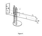
Figure 3 présente une autre variante de réalisation du dispositif selon l'invention comportant un grand nombre de marqueurs. - La
Figure 4 présente la variante de lafigure 3 après rotation de 90°.
- The
Figure 1 presents an alternative embodiment of the device according to the invention comprising only three markers. - The
Figure 2 presents another variant embodiment of the device according to the invention comprising six markers, - The
Figure 3 presents another variant embodiment of the device according to the invention comprising a large number of markers. - The
Figure 4 presents the variant of thefigure 3 after 90 ° rotation.
Sur la
Sur la
Sur les
Sur la
L'utilisation du dispositif selon l'invention se caractérise en ce que l'on place ledit dispositif entre ladite source de rayon X 11 et ledit récepteur de rayons X 12 de manière à ce que le plan vertical dudit repère tridimensionnel soit parallèle au plan dudit récepteur 12, en ce que l'on place le patient sur ledit plateau tournant 13, en ce que le patient se maintient dans une position de repos stable et figée à l'aide desdites poignées 15, on effectue un premier cliché du patient dans cette position, en ce que l'on effectue une rotation dudit plateau tournant 13 et éventuellement une translation de dégagement ou d'engagement du dispositif au plus près du film, ladite rotation étant de 90° et entraînant solidairement ladite armature 14, lesdits marqueurs 1,16 et ledit patient et en ce que l'on effectue un deuxième cliché dudit patient.The use of the device according to the invention is characterized in that said device is placed between said
L'utilisation du dispositif se révèle alors particulièrement simple à la fois pour le praticien et le patient qui est placé dans une position de repos telle qu'il reste immobile durant toute la prise des clichés même lors de la rotation ou de la translation du plateau tournant 13.The use of the device then proves particularly simple for both the practitioner and the patient who is placed in a rest position such that he remains motionless during the entire shooting even during the rotation or the translation of the plateau turning 13.
La source de rayons X 11 est localisée en face du sujet (qui reste quasiment immobile sur le dispositif) puis le système est placé dans deux positions successives, indexées de telle manière à orienter les axes du repère de l'espace (X,Y,Z) respectivement parallèles et perpendiculaires au plan du film radiographique 12.The
Les marqueurs radio-opaques 1,16 se projettent alors dans l'image radiographique selon la disposition suivante : le marqueur 1 identifié comme origine du repère et les lignes verticales sont visibles dans les deux images, une des deux lignes horizontales est visible dans l'une des deux images. Il s'agit de la ligne qui est parallèle au plan du film.The
On appelle lignes verticales ou horizontales, les lignes obtenues en reliant les marqueurs 1,4,5,6,7,10,16 du système par exemple dans le cas d'un dispositif selon l'invention conçu sur le principe décrit et présenté aux
De cette façon, un repère de référence pour chaque image radiographique peut être défini, Rimage1 (O1, u1, v1, w1)
Par conséquent, le dispositif de stéréoradiographie permet de déterminer des conditions spécifiques pour la prise des images radiographiques.Therefore, the stereoradiography device makes it possible to determine specific conditions for taking radiographic images.
Premièrement, l'orientation du repère de référence de l'espace (Respace) par rapport aux deux repères de référence des images (Rimage1 et Rimage2) est fixée et connue. Les relations géométriques entre les coordonnées tridimensionnelles et bidimensionnelles (images 1 et 2) sont établies en fonction de deux signes m 1 et m 2 connus, imposés par la position du système tournant. La matrice M de passage de Respace à Rimage est alors définie par : 
(m1 , m2 ) = (1,0) pour la radiographie latérale droite
(m1 , m2 ) = (-1,0) pour la radiographie latérale gauche
(m1 , m2 ) = (0,-1) pour la radiographie postero-antérieure
(m1 , m2 ) = (0,1) pour la radiographie antero-postérieureFirst, the orientation of the reference reference of the space (R space ) with respect to the two reference reference marks of the images (R image1 and R image2 ) is fixed and known. The geometric relations between the three-dimensional and two-dimensional coordinates (
( m 1 , m 2 ) = (1.0) for the right lateral radiograph
( m 1 , m 2 ) = (-1.0) for the left lateral radiograph
( m 1 , m 2 ) = (0, -1) for postero-anterior radiography
( m 1 , m 2 ) = (0,1) for anteroposterior radiography
Ensuite, la distance entre le film radiographique 12 (d) et la source 11 ainsi que la hauteur de celle-ci par rapport au système (Zs) reste inchangée pendant la prise successive des deux images, seul le dispositif est déplacé en rotation et éventuellement en translation.Then, the distance between the radiographic film 12 (d) and the
Enfin, pour chaque cliché, la position de la source de rayons X 11 exprimée par rapport aux repères de référence des images (us1, vs1, us2, vs2 et d) et exprimée par rapport au repère de référence de l'espace (Xs1, Ys1, Xs2, Ys2 et Zs) sont liées géométriquement du fait de la construction des repères en projection.Finally, for each image, the position of the
Ainsi, ces conditions spécifiques, imposées par le dispositif, permettent de définir l'environnement de la prise des images radiographiques avec un nombre d'inconnues géométriques indépendantes limité à six (au lieu de dix-huit dans le cas général).Thus, these specific conditions imposed by the device make it possible to define the environment for taking radiographic images with a number of independent geometric unknowns limited to six (instead of eighteen in the general case).
Il est alors nécessaire de calibrer l'environnement radiographique des prises de vue, c'est-à-dire déterminer les positions relatives des images par rapport aux sources de rayons X, qui peuvent être décrites par 6 inconnues indépendantes (par exemple).It is then necessary to calibrate the radiographic environment of the shots, that is to say to determine the relative positions of the images with respect to the sources of X-rays, which can be described by 6 independent unknowns (for example).
Le calcul des paramètres indépendants de l'environnement radiographique (susmentionnés ou autres) est effectué selon une procédure de calibrage spécifique en utilisant au mieux la configuration des marqueurs radio opaques (l'information projetée est différente d'une image à l'autre et selon les axes considérés) et en intégrant les invariants et les relations géométriques dues à la construction des repères en projection et citées ci-dessus.The calculation of the parameters independent of the radiographic environment (mentioned above or otherwise) is carried out according to a specific calibration procedure by making best use of the configuration of the opaque radio markers (the projected information is different from one image to another and according to the considered axes) and by integrating the invariants and geometric relations due to the construction of the projection markers mentioned above.
En particulier, on peut calculer spécifiquement Xs1, Ys1, Xs2, Ys2, Zs et d, en tant que paramètre de l'environnement radiographique par une procédure spécifique, considérant séparément et successivement les plans verticaux et horizontaux des deux images.In particular, X s1 , Y s1 , X s2 , Y s2 , Z s and d can be specifically calculated as a parameter of the radiographic environment by a specific procedure, considering separately and successively the vertical and horizontal planes of the two images. .
Selon la configuration des marqueurs la procédure peut prendre la forme suivante :Depending on the configuration of the markers the procedure can take the following form:
La première étape de la procédure consiste à déterminer les paramètres liés au plan vertical de l'image 1 (d, Zs et Ys1) en considérant les coordonnées des lignes de marqueurs verticales (exprimées dans Respace) et leur projection (exprimées dans Rimage1) .On utilise alors la méthode des moindres carrés avec les équations : 
La seconde étape de la procédure consiste à déterminer le paramètre lié au plan horizontal de l'image 1 (Xs1) en considérant les coordonnées des lignes de marqueurs horizontales (exprimées dans Respace) et leur projection (exprimées dans Rimage1) ainsi que les paramètres déjà calculés (d et Ys1). On utilise ici encore la méthode des moindres carrés sur : 
La troisième étape de la procédure consiste à déterminer le paramètre lié au plan vertical de l'image 2 (Xs2) en considérant les coordonnées des lignes de marqueurs verticales (exprimées dans Respace) et leur projection (exprimées dans Rimage2) ainsi que les paramètres déjà calculés (d et Zs).The third step of the procedure consists in determining the parameter related to the vertical plane of the image 2 (X s2 ) by considering the coordinates of the lines of vertical markers (expressed in R space ) and their projection (expressed in R image2 ) as well as already calculated parameters (d and Z s ).
On utilise alors : 

La quatrième et dernière étape de la procédure consiste à déterminer le paramètre lié au plan horizontal de l'image 2 (Ys2) en considérant les coordonnées des lignes de marqueurs horizontales (exprimées dans Respace) et leur projection (exprimées dans Rimage2) ainsi que les paramètres déjà calculés (d et Xs2) .On utilise alors : 
Le calcul des paramètres géométriques de l'environnement est effectué par un programme informatique dont les données d'entrée introduites sont les suivantes :
- L'orientation des radiographies prises sur le dispositif (postéro-antérieure ou antéro-postérieure et latérale droite ou latérale gauche).
- Les coordonnées des marqueurs dans chaque image. Ces coordonnées sont obtenues lors d'une étape d'identification de la projection des marqueurs dans le film, effectuée par un procédé standard (table à numériser ou logiciel informatique après numérisation des films radiographiques).
- Les coordonnées tridimensionnelles des marqueurs, obtenues une fois pour toutes lors de la fabrication du dispositif (données de fabrication, verniers, pieds à coulisses).
- The orientation of radiographs taken on the device (posteroanterior or anteroposterior and lateral right or left side).
- The coordinates of the markers in each image. These coordinates are obtained during a step of identifying the projection of the markers in the film, carried out by a standard method (digitizing table or computer software after digitization of the radiographic films).
- The three-dimensional coordinates of the markers, obtained once and for all during the manufacture of the device (manufacturing data, verniers, calipers).
A la fin du programme, l'ensemble des paramètres géométriques de l'environnement est calculé par un algorithme approprié (les six paramètres indépendants plus les autres, déduits ou connus à priori).At the end of the program, the set of geometric parameters of the environment is calculated by an appropriate algorithm (the six independent parameters plus the others, deduced or known a priori).
La présente invention n'est bien entendu pas limitée aux variantes d'exécution présentées ci avant à titre d'exemples illustratifs non limitatifs ni aux variantes de mise en oeuvre du dispositif selon l'invention dans les procédés décrits.The present invention is of course not limited to the embodiments described above by way of nonlimiting illustrative examples nor to the variants of implementation of the device according to the invention in the methods described.
Ainsi, il sera possible de combiner le dispositif selon l'invention avec par exemple une table de pression permettant de déterminer la ligne de gravité du corps et pouvoir utiliser cette information en corrélation avec celles que fournit directement le dispositif selon l'invention.Thus, it will be possible to combine the device according to the invention with for example a pressure table for determining the gravity line of the body and be able to use this information in correlation with those provided directly by the device according to the invention.
Claims (11)
- Stereoradiography device intended to position a subject to be X-rayed and to be interposed between an X-ray source (11) and a vertical receiver (12) for said rays, comprising a horizontal plate (13) able to move in rotation and optionally in unidirectional translation, wherein said plate (13) can be oriented in two referenced positions at an angle of 90° with respect to each other and enabling two shots to be taken corresponding to two positions of the subject orthogonal to each other and in that the device also comprises a vertical frame (14) secured to said horizontal plate (13) and, optionally, a complementary holding device (15) intended to accommodate said subject and to hold him in a stable position, and at least three markers (16) made from radio-opaque material, one of said markers (1) being identified as the origin of an orthogonal three-dimensional reference frame, the other markers (16) being placed so as to provide, by projection, knowledge of at least one distance value between said markers (16) along the three axis x, y and z of said reference frame, respectively Lx, Ly and H, characterized in that said at least three markers (16) are placed securely on said frame (14).
- Device according to claim 1, characterized in that it comprises three markers made from radio-opaque material, the first marker (1) being identified as the origin of said reference frame, said second marker (2) being placed in a vertical plane comprising said first marker and at a height H known with respect to said first marker and at a distance Ly with respect to the vertical axis of said reference frame and the third marker (3) being situated in a horizontal plane passing through said first marker and vertically in line with said first marker and at a distance Lx with respect to said first marker.
- Device according to claim 1, characterized in that it comprises six markers made from radio-opaque material, the first marker (1) being identified as the origin of said reference frame, four markers (4, 5, 6, 7) being placed in a vertical plane comprising said first marker (1) and forming two dipoles (8, 9), each of the dipoles (8, 9) being placed along the vertical, the first dipole (8) defining a straight line passing through said first marker (1), the second dipole (9) being situated at a distance Ly with respect to said first dipole (9), the two markers (4 and 5, 6 and 7) of each dipole (8 and 9) being separated by a height H and the sixth marker (10) being situated in a horizontal plane passing through said first marker (1) and vertically in line with said first marker (1) and at a distance Lx with respect to said first marker (1).
- Device according to claim 1, characterized in that it comprises more than six markers (16) made from radio-opaque material placed along two parallel vertical lines and two horizontal lines perpendicular to said vertical lines and in that one of said markers (1) is identified as the origin of said reference frame.
- Device according to any one of claims 1 to 4, characterized in that said marker (1) identified as the origin of said three-dimensional reference frame comprises a marking in radio-opaque material enabling it to be distinguished from the other markers (16).
- Device according to any one of claims 1 to 4, characterized in that said radio-opaque material is a steel.
- Method of using the device according to one of claims 1 to 6, characterized in that said device is placed between said X-ray source (11) and said X-ray receiver (12) so that a vertical plane of said three-dimensional reference frame is parallel to the plane of said receiver (12), in that the patient is placed on said rotating plate (13), in that the patient holds himself in a stable position of rest fixed by means of handles (15), in that a first shot of the patient is effected in this position, in that a rotation of said rotating plate (13) is effected and optionally a disengagement or engagement translation of the device as close as possible to the film, said rotation being 90° and integrally driving said frame (14), said markers (1, 16) and said patient, and in that a second shot of said patient is effected.
- Method of calibrating the device according to any one of claims 1 to 6, characterized in that 6 independent parameters of the radiographic environment are specifically calculated by best using the configuration of the radio-opaque markers and integrating the invariants and the geometric relationships due to the construction of the reference frames in projection.
- Method according to claim 8, characterized in that the parameters of the radiographic environment respectively Xs1, Ys1, Xs2, Ys2, Zs and d are specifically calculated by considering separately and successively the vertical and horizontal planes of the two images.
- Method according to either one of claims 8 and 9, characterized in that:- the parameters relating to the vertical plane of the first image are determined by considering the coordinates of the lines of said vertical markers and their projection,- the parameter relating to the horizontal plane of the first image is determined by considering the coordinates of the lines of horizontal markers and the projection thereof as well as the parameters already calculated,- the parameter relating to the vertical plane of the second image is determined by considering the coordinates of the lines of vertical markers and the projection thereof as well as the parameters already calculated, and finally- the parameter relating to the horizontal plane of the second image is determined by considering the coordinates of the lines of horizontal markers and the projection thereof as well as the parameters already calculated.
- Method of processing radiographs comprising a stage of obtaining radiographs by means of the device according to any one of claims 1 to 6 so as to allow calibration, characterized in that the following are introduced:- the orientation of the radiographs taken on said device,- the coordinates of the markers in each image by an identification of the projection of the markers in the film,- the three-dimensional coordinates of the markers, obtained during the manufacture of the device,and in that all the geometric parameters of the environment are calculated by means of a suitable algorithm.
Applications Claiming Priority (3)
| Application Number | Priority Date | Filing Date | Title |
|---|---|---|---|
| US38237202P | 2002-05-23 | 2002-05-23 | |
| US382372P | 2002-05-23 | ||
| PCT/FR2003/001576 WO2003099124A1 (en) | 2002-05-23 | 2003-05-23 | Stereoradiography device and method for the use thereof |
Publications (2)
| Publication Number | Publication Date |
|---|---|
| EP1511421A1 EP1511421A1 (en) | 2005-03-09 |
| EP1511421B1 true EP1511421B1 (en) | 2012-09-19 |
Family
ID=29584401
Family Applications (1)
| Application Number | Title | Priority Date | Filing Date |
|---|---|---|---|
| EP03755198A Expired - Lifetime EP1511421B1 (en) | 2002-05-23 | 2003-05-23 | Stereoradiography device and method for the use thereof |
Country Status (5)
| Country | Link |
|---|---|
| US (1) | US7241045B2 (en) |
| EP (1) | EP1511421B1 (en) |
| AU (1) | AU2003249420A1 (en) |
| CA (1) | CA2487044C (en) |
| WO (1) | WO2003099124A1 (en) |
Families Citing this family (10)
| Publication number | Priority date | Publication date | Assignee | Title |
|---|---|---|---|---|
| US7873147B2 (en) * | 2007-11-05 | 2011-01-18 | The University Of Western Ontario | Radiostereometric calibration cage |
| US7677801B2 (en) * | 2008-06-09 | 2010-03-16 | Peyman Pakzaban | Non-invasive method and apparatus to locate incision site for spinal surgery |
| EP2245986B1 (en) * | 2008-08-22 | 2013-10-16 | BrainLAB AG | Arrangement of x-ray markers in the form of a pyramid |
| DE202009017401U1 (en) * | 2009-12-22 | 2010-05-12 | Corpus.E Ag | Calibration-free and accurate optical detection of the spatial form |
| DE102010056042A1 (en) | 2010-12-23 | 2012-06-28 | Yxlon International Gmbh | Method and device for visual inspection of a test object to be checked by means of X-ray radiation |
| US10143438B2 (en) | 2015-08-06 | 2018-12-04 | Xiang Zhang | System for 3D object modeling and tracking in X-ray imaging |
| FR3040867A1 (en) | 2015-09-11 | 2017-03-17 | Thales Sa | MIRE AND METHOD FOR CALIBRATING AN X-RAY IMAGING SYSTEM |
| US10657665B2 (en) * | 2016-12-07 | 2020-05-19 | Electronics And Telecommunications Research Institute | Apparatus and method for generating three-dimensional information |
| JP6988732B2 (en) * | 2018-08-02 | 2022-01-05 | 株式会社島津製作所 | Radiation image processing equipment and radiation image processing method |
| WO2020185706A1 (en) * | 2019-03-08 | 2020-09-17 | Butler William E | Temporal calibration of an angiographic imaging system |
Family Cites Families (11)
| Publication number | Priority date | Publication date | Assignee | Title |
|---|---|---|---|---|
| US4719646A (en) | 1986-05-08 | 1988-01-12 | Queen's University | X-ray apparatus with source distortion compensation |
| US5603318A (en) * | 1992-04-21 | 1997-02-18 | University Of Utah Research Foundation | Apparatus and method for photogrammetric surgical localization |
| FR2720930B1 (en) | 1994-06-09 | 1996-10-31 | Medinov Sa | Cotyloid implant insert, made of a biocompatible and radiolucent synthetic material. |
| DE19703556A1 (en) * | 1997-01-31 | 1998-08-06 | Philips Patentverwaltung | Method and arrangement for determining the position in X-ray imaging |
| US6055449A (en) * | 1997-09-22 | 2000-04-25 | Siemens Corporate Research, Inc. | Method for localization of a biopsy needle or similar surgical tool in a radiographic image |
| DE19746096A1 (en) * | 1997-10-17 | 1999-05-06 | Siemens Ag | X-ray device |
| US5967982A (en) * | 1997-12-09 | 1999-10-19 | The Cleveland Clinic Foundation | Non-invasive spine and bone registration for frameless stereotaxy |
| US6044132A (en) | 1997-12-31 | 2000-03-28 | Siemens Corporate Research, Inc. | Apparatus for providing markers on an image, for use in conjunction with C-arm calibration apparatus |
| US6118845A (en) * | 1998-06-29 | 2000-09-12 | Surgical Navigation Technologies, Inc. | System and methods for the reduction and elimination of image artifacts in the calibration of X-ray imagers |
| US6381302B1 (en) * | 2000-07-05 | 2002-04-30 | Canon Kabushiki Kaisha | Computer assisted 2D adjustment of stereo X-ray images |
| FR2803507B1 (en) | 2000-01-10 | 2003-05-30 | Eric Berthonnaud | DEVICE FOR EVALUATING THE BALANCE POSITION OF THE HUMAN BODY |
-
2003
- 2003-05-23 WO PCT/FR2003/001576 patent/WO2003099124A1/en not_active Application Discontinuation
- 2003-05-23 US US10/515,230 patent/US7241045B2/en not_active Expired - Lifetime
- 2003-05-23 EP EP03755198A patent/EP1511421B1/en not_active Expired - Lifetime
- 2003-05-23 AU AU2003249420A patent/AU2003249420A1/en not_active Abandoned
- 2003-05-23 CA CA2487044A patent/CA2487044C/en not_active Expired - Lifetime
Also Published As
| Publication number | Publication date |
|---|---|
| WO2003099124A1 (en) | 2003-12-04 |
| AU2003249420A8 (en) | 2003-12-12 |
| US20050147206A1 (en) | 2005-07-07 |
| EP1511421A1 (en) | 2005-03-09 |
| CA2487044A1 (en) | 2003-12-04 |
| US7241045B2 (en) | 2007-07-10 |
| AU2003249420A1 (en) | 2003-12-12 |
| CA2487044C (en) | 2010-05-11 |
Similar Documents
| Publication | Publication Date | Title |
|---|---|---|
| US11464475B2 (en) | Self-calibrating technique for x-ray imaging scanners | |
| CA2003265C (en) | Process for the correlation of tridimensional capturings of human organs and device for the implementation of the same | |
| EP1511421B1 (en) | Stereoradiography device and method for the use thereof | |
| CA2396563C (en) | Device for evaluating a position of balance for the human body | |
| WO2016012726A1 (en) | System and method for measuring the displacements of a vertebral column | |
| FR2700909A1 (en) | Automatic method and device for geometric calibration of an X-ray imaging system | |
| FR2779339A1 (en) | MATCHING METHOD AND APPARATUS FOR ROBOTIC SURGERY, AND MATCHING DEVICE COMPRISING APPLICATION | |
| FR2904455A1 (en) | COMPUTERIZED IMAGING METHOD FOR THREE DIMENSIONAL RECONSTRUCTION FROM TWO DIMENSIONAL RADIOGRAPHIC IMAGES; DEVICE FOR IMPLEMENTING. | |
| US11478213B2 (en) | Low dose digital tomosynthesis system and method using artificial intelligence | |
| FR2881337A1 (en) | Breast imaging method for premature screening of e.g. cancerous tumors, involves determining, before acquisition of image, X-field and compression plate positions based on angle between patient longitudinal axis and breast support normal | |
| FR3068880A1 (en) | METHOD AND SYSTEM FOR ONLINE CALIBRATION OF MEDICAL DEVICE WITH X-RAYS | |
| FR2705223A1 (en) | Method for acquiring images of a body by rotational placement | |
| CA3077228A1 (en) | Radiographic imaging method, radiographic image processing device, and radiographic imaging device | |
| GB2358752A (en) | Surface or volumetric data processing method and apparatus | |
| FR2757373A1 (en) | DEVICE FOR DETERMINING A DISPLACEMENT BETWEEN RELATIVE POSITIONS OF TWO DENTAL CASTLES AND SYSTEM FOR SIMULATING AN INTERVENTION IN ORTHOGNATIC SURGERY | |
| EP1496800B1 (en) | Real-time navigational aid system for radiography | |
| EP3731758A1 (en) | Method and system for calibrating an x-ray imaging system | |
| EP1088525A1 (en) | Registration process of two medical images from a patient and its device | |
| JP2011050738A (en) | Processing method for three-dimensionally reconstruction of object from single view | |
| BE1013837A3 (en) | SYSTEM FOR ACQUIRING RADIOGRAPHIC IMAGES AND PANORAMIC EDITING. | |
| FR2705224A1 (en) | Method for acquiring images of a body by rotational placement of a radiology device, in particular an angiography device | |
| EP1400909A1 (en) | Detection and correction of orientation error of a digital radiographic image | |
| FR3092746A1 (en) | Surgical instrument for a robotic surgery facility | |
| Vaquero et al. | PET and CT Image Registration of the Rat Brain and Skull using the AIR Algorithm | |
| FR3080017A1 (en) | QUICK CALIBRATION SYSTEM FOR SURGICAL NAVIGATION |
Legal Events
| Date | Code | Title | Description |
|---|---|---|---|
| PUAI | Public reference made under article 153(3) epc to a published international application that has entered the european phase |
Free format text: ORIGINAL CODE: 0009012 |
|
| 17P | Request for examination filed |
Effective date: 20041209 |
|
| AK | Designated contracting states |
Kind code of ref document: A1 Designated state(s): AT BE BG CH CY CZ DE DK EE ES FI FR GB GR HU IE IT LI LU MC NL PT RO SE SI SK TR |
|
| AX | Request for extension of the european patent |
Extension state: AL LT LV MK |
|
| RIN1 | Information on inventor provided before grant (corrected) |
Inventor name: DUMAS, RAPHAEL Inventor name: BATAILLE, PHILIPPE Inventor name: MITTON, DAVID Inventor name: SKALLI, WAFA Inventor name: QUIDET, DAMIEN |
|
| DAX | Request for extension of the european patent (deleted) | ||
| 17Q | First examination report despatched |
Effective date: 20110207 |
|
| RAP1 | Party data changed (applicant data changed or rights of an application transferred) |
Owner name: ECOLE NATIONALE SUPERIEURE D'ARTS ET METIERS ENSAM |
|
| GRAP | Despatch of communication of intention to grant a patent |
Free format text: ORIGINAL CODE: EPIDOSNIGR1 |
|
| GRAS | Grant fee paid |
Free format text: ORIGINAL CODE: EPIDOSNIGR3 |
|
| GRAA | (expected) grant |
Free format text: ORIGINAL CODE: 0009210 |
|
| AK | Designated contracting states |
Kind code of ref document: B1 Designated state(s): AT BE BG CH CY CZ DE DK EE ES FI FR GB GR HU IE IT LI LU MC NL PT RO SE SI SK TR |
|
| REG | Reference to a national code |
Ref country code: GB Ref legal event code: FG4D Free format text: NOT ENGLISH |
|
| REG | Reference to a national code |
Ref country code: CH Ref legal event code: EP |
|
| REG | Reference to a national code |
Ref country code: IE Ref legal event code: FG4D Free format text: LANGUAGE OF EP DOCUMENT: FRENCH |
|
| REG | Reference to a national code |
Ref country code: AT Ref legal event code: REF Ref document number: 575597 Country of ref document: AT Kind code of ref document: T Effective date: 20121015 |
|
| REG | Reference to a national code |
Ref country code: DE Ref legal event code: R096 Ref document number: 60342140 Country of ref document: DE Effective date: 20121115 |
|
| PG25 | Lapsed in a contracting state [announced via postgrant information from national office to epo] |
Ref country code: FI Free format text: LAPSE BECAUSE OF FAILURE TO SUBMIT A TRANSLATION OF THE DESCRIPTION OR TO PAY THE FEE WITHIN THE PRESCRIBED TIME-LIMIT Effective date: 20120919 Ref country code: CY Free format text: LAPSE BECAUSE OF FAILURE TO SUBMIT A TRANSLATION OF THE DESCRIPTION OR TO PAY THE FEE WITHIN THE PRESCRIBED TIME-LIMIT Effective date: 20120919 |
|
| REG | Reference to a national code |
Ref country code: NL Ref legal event code: VDEP Effective date: 20120919 |
|
| REG | Reference to a national code |
Ref country code: AT Ref legal event code: MK05 Ref document number: 575597 Country of ref document: AT Kind code of ref document: T Effective date: 20120919 |
|
| PG25 | Lapsed in a contracting state [announced via postgrant information from national office to epo] |
Ref country code: SE Free format text: LAPSE BECAUSE OF FAILURE TO SUBMIT A TRANSLATION OF THE DESCRIPTION OR TO PAY THE FEE WITHIN THE PRESCRIBED TIME-LIMIT Effective date: 20120919 Ref country code: SI Free format text: LAPSE BECAUSE OF FAILURE TO SUBMIT A TRANSLATION OF THE DESCRIPTION OR TO PAY THE FEE WITHIN THE PRESCRIBED TIME-LIMIT Effective date: 20120919 Ref country code: GR Free format text: LAPSE BECAUSE OF FAILURE TO SUBMIT A TRANSLATION OF THE DESCRIPTION OR TO PAY THE FEE WITHIN THE PRESCRIBED TIME-LIMIT Effective date: 20121220 |
|
| PG25 | Lapsed in a contracting state [announced via postgrant information from national office to epo] |
Ref country code: RO Free format text: LAPSE BECAUSE OF FAILURE TO SUBMIT A TRANSLATION OF THE DESCRIPTION OR TO PAY THE FEE WITHIN THE PRESCRIBED TIME-LIMIT Effective date: 20120919 Ref country code: CZ Free format text: LAPSE BECAUSE OF FAILURE TO SUBMIT A TRANSLATION OF THE DESCRIPTION OR TO PAY THE FEE WITHIN THE PRESCRIBED TIME-LIMIT Effective date: 20120919 Ref country code: NL Free format text: LAPSE BECAUSE OF FAILURE TO SUBMIT A TRANSLATION OF THE DESCRIPTION OR TO PAY THE FEE WITHIN THE PRESCRIBED TIME-LIMIT Effective date: 20120919 Ref country code: ES Free format text: LAPSE BECAUSE OF FAILURE TO SUBMIT A TRANSLATION OF THE DESCRIPTION OR TO PAY THE FEE WITHIN THE PRESCRIBED TIME-LIMIT Effective date: 20121230 Ref country code: EE Free format text: LAPSE BECAUSE OF FAILURE TO SUBMIT A TRANSLATION OF THE DESCRIPTION OR TO PAY THE FEE WITHIN THE PRESCRIBED TIME-LIMIT Effective date: 20120919 |
|
| PG25 | Lapsed in a contracting state [announced via postgrant information from national office to epo] |
Ref country code: SK Free format text: LAPSE BECAUSE OF FAILURE TO SUBMIT A TRANSLATION OF THE DESCRIPTION OR TO PAY THE FEE WITHIN THE PRESCRIBED TIME-LIMIT Effective date: 20120919 Ref country code: PT Free format text: LAPSE BECAUSE OF FAILURE TO SUBMIT A TRANSLATION OF THE DESCRIPTION OR TO PAY THE FEE WITHIN THE PRESCRIBED TIME-LIMIT Effective date: 20130121 |
|
| PG25 | Lapsed in a contracting state [announced via postgrant information from national office to epo] |
Ref country code: AT Free format text: LAPSE BECAUSE OF FAILURE TO SUBMIT A TRANSLATION OF THE DESCRIPTION OR TO PAY THE FEE WITHIN THE PRESCRIBED TIME-LIMIT Effective date: 20120919 |
|
| PLBE | No opposition filed within time limit |
Free format text: ORIGINAL CODE: 0009261 |
|
| STAA | Information on the status of an ep patent application or granted ep patent |
Free format text: STATUS: NO OPPOSITION FILED WITHIN TIME LIMIT |
|
| PG25 | Lapsed in a contracting state [announced via postgrant information from national office to epo] |
Ref country code: DK Free format text: LAPSE BECAUSE OF FAILURE TO SUBMIT A TRANSLATION OF THE DESCRIPTION OR TO PAY THE FEE WITHIN THE PRESCRIBED TIME-LIMIT Effective date: 20120919 Ref country code: BG Free format text: LAPSE BECAUSE OF FAILURE TO SUBMIT A TRANSLATION OF THE DESCRIPTION OR TO PAY THE FEE WITHIN THE PRESCRIBED TIME-LIMIT Effective date: 20121219 |
|
| 26N | No opposition filed |
Effective date: 20130620 |
|
| PG25 | Lapsed in a contracting state [announced via postgrant information from national office to epo] |
Ref country code: IT Free format text: LAPSE BECAUSE OF FAILURE TO SUBMIT A TRANSLATION OF THE DESCRIPTION OR TO PAY THE FEE WITHIN THE PRESCRIBED TIME-LIMIT Effective date: 20120919 |
|
| REG | Reference to a national code |
Ref country code: DE Ref legal event code: R097 Ref document number: 60342140 Country of ref document: DE Effective date: 20130620 |
|
| BERE | Be: lapsed |
Owner name: ECOLE NATIONALE SUPERIEURE D'ARTS ET METIERS ENSAM Effective date: 20130531 |
|
| PG25 | Lapsed in a contracting state [announced via postgrant information from national office to epo] |
Ref country code: MC Free format text: LAPSE BECAUSE OF FAILURE TO SUBMIT A TRANSLATION OF THE DESCRIPTION OR TO PAY THE FEE WITHIN THE PRESCRIBED TIME-LIMIT Effective date: 20120919 |
|
| REG | Reference to a national code |
Ref country code: CH Ref legal event code: PL |
|
| PG25 | Lapsed in a contracting state [announced via postgrant information from national office to epo] |
Ref country code: LI Free format text: LAPSE BECAUSE OF NON-PAYMENT OF DUE FEES Effective date: 20130531 Ref country code: CH Free format text: LAPSE BECAUSE OF NON-PAYMENT OF DUE FEES Effective date: 20130531 |
|
| REG | Reference to a national code |
Ref country code: IE Ref legal event code: MM4A |
|
| PG25 | Lapsed in a contracting state [announced via postgrant information from national office to epo] |
Ref country code: BE Free format text: LAPSE BECAUSE OF NON-PAYMENT OF DUE FEES Effective date: 20130531 |
|
| PG25 | Lapsed in a contracting state [announced via postgrant information from national office to epo] |
Ref country code: IE Free format text: LAPSE BECAUSE OF NON-PAYMENT OF DUE FEES Effective date: 20130523 |
|
| REG | Reference to a national code |
Ref country code: FR Ref legal event code: PLFP Year of fee payment: 13 |
|
| PG25 | Lapsed in a contracting state [announced via postgrant information from national office to epo] |
Ref country code: TR Free format text: LAPSE BECAUSE OF FAILURE TO SUBMIT A TRANSLATION OF THE DESCRIPTION OR TO PAY THE FEE WITHIN THE PRESCRIBED TIME-LIMIT Effective date: 20120919 |
|
| PG25 | Lapsed in a contracting state [announced via postgrant information from national office to epo] |
Ref country code: LU Free format text: LAPSE BECAUSE OF NON-PAYMENT OF DUE FEES Effective date: 20130523 Ref country code: HU Free format text: LAPSE BECAUSE OF FAILURE TO SUBMIT A TRANSLATION OF THE DESCRIPTION OR TO PAY THE FEE WITHIN THE PRESCRIBED TIME-LIMIT; INVALID AB INITIO Effective date: 20030523 |
|
| REG | Reference to a national code |
Ref country code: FR Ref legal event code: PLFP Year of fee payment: 14 |
|
| REG | Reference to a national code |
Ref country code: FR Ref legal event code: PLFP Year of fee payment: 15 |
|
| REG | Reference to a national code |
Ref country code: FR Ref legal event code: PLFP Year of fee payment: 16 |
|
| PGFP | Annual fee paid to national office [announced via postgrant information from national office to epo] |
Ref country code: GB Payment date: 20220519 Year of fee payment: 20 Ref country code: FR Payment date: 20220422 Year of fee payment: 20 Ref country code: DE Payment date: 20220511 Year of fee payment: 20 |
|
| REG | Reference to a national code |
Ref country code: DE Ref legal event code: R071 Ref document number: 60342140 Country of ref document: DE |
|
| REG | Reference to a national code |
Ref country code: GB Ref legal event code: PE20 Expiry date: 20230522 |
|
| PG25 | Lapsed in a contracting state [announced via postgrant information from national office to epo] |
Ref country code: GB Free format text: LAPSE BECAUSE OF EXPIRATION OF PROTECTION Effective date: 20230522 |