EP1168249B1 - Radiographic imaging method and device for three-dimensional reconstruction with low dose of irradiation - Google Patents
Radiographic imaging method and device for three-dimensional reconstruction with low dose of irradiation Download PDFInfo
- Publication number
- EP1168249B1 EP1168249B1 EP01401511A EP01401511A EP1168249B1 EP 1168249 B1 EP1168249 B1 EP 1168249B1 EP 01401511 A EP01401511 A EP 01401511A EP 01401511 A EP01401511 A EP 01401511A EP 1168249 B1 EP1168249 B1 EP 1168249B1
- Authority
- EP
- European Patent Office
- Prior art keywords
- generic model
- marks
- model
- check
- images
- Prior art date
- Legal status (The legal status is an assumption and is not a legal conclusion. Google has not performed a legal analysis and makes no representation as to the accuracy of the status listed.)
- Expired - Lifetime
Links
Images

Classifications
-
- A—HUMAN NECESSITIES
- A61—MEDICAL OR VETERINARY SCIENCE; HYGIENE
- A61B—DIAGNOSIS; SURGERY; IDENTIFICATION
- A61B6/00—Apparatus for radiation diagnosis, e.g. combined with radiation therapy equipment
- A61B6/44—Constructional features of apparatus for radiation diagnosis
- A61B6/4429—Constructional features of apparatus for radiation diagnosis related to the mounting of source units and detector units
- A61B6/4435—Constructional features of apparatus for radiation diagnosis related to the mounting of source units and detector units the source unit and the detector unit being coupled by a rigid structure
- A61B6/4441—Constructional features of apparatus for radiation diagnosis related to the mounting of source units and detector units the source unit and the detector unit being coupled by a rigid structure the rigid structure being a C-arm or U-arm
-
- A—HUMAN NECESSITIES
- A61—MEDICAL OR VETERINARY SCIENCE; HYGIENE
- A61B—DIAGNOSIS; SURGERY; IDENTIFICATION
- A61B6/00—Apparatus for radiation diagnosis, e.g. combined with radiation therapy equipment
- A61B6/06—Diaphragms
-
- A—HUMAN NECESSITIES
- A61—MEDICAL OR VETERINARY SCIENCE; HYGIENE
- A61B—DIAGNOSIS; SURGERY; IDENTIFICATION
- A61B6/00—Apparatus for radiation diagnosis, e.g. combined with radiation therapy equipment
- A61B6/50—Clinical applications
- A61B6/505—Clinical applications involving diagnosis of bone
-
- G—PHYSICS
- G06—COMPUTING; CALCULATING OR COUNTING
- G06T—IMAGE DATA PROCESSING OR GENERATION, IN GENERAL
- G06T7/00—Image analysis
- G06T7/50—Depth or shape recovery
- G06T7/55—Depth or shape recovery from multiple images
- G06T7/564—Depth or shape recovery from multiple images from contours
-
- G—PHYSICS
- G06—COMPUTING; CALCULATING OR COUNTING
- G06T—IMAGE DATA PROCESSING OR GENERATION, IN GENERAL
- G06T2207/00—Indexing scheme for image analysis or image enhancement
- G06T2207/10—Image acquisition modality
- G06T2207/10072—Tomographic images
- G06T2207/10112—Digital tomosynthesis [DTS]
-
- G—PHYSICS
- G06—COMPUTING; CALCULATING OR COUNTING
- G06T—IMAGE DATA PROCESSING OR GENERATION, IN GENERAL
- G06T2207/00—Indexing scheme for image analysis or image enhancement
- G06T2207/10—Image acquisition modality
- G06T2207/10116—X-ray image
-
- G—PHYSICS
- G06—COMPUTING; CALCULATING OR COUNTING
- G06T—IMAGE DATA PROCESSING OR GENERATION, IN GENERAL
- G06T2207/00—Indexing scheme for image analysis or image enhancement
- G06T2207/30—Subject of image; Context of image processing
- G06T2207/30004—Biomedical image processing
Definitions
- the present invention relates to radiographic imaging methods and devices for three-dimensional low dose radiation reconstruction.
- step (d) is a kriging step consisting of interpolation / extrapolation of the generic model of the object to be observed, which gives estimated positions of a large number of references of the model to three dimensions of the object to be observed according to the measured coordinates of the stereo-corresponding control marks and according to the geometry of the generic model. This stage of kriging has been described in particular by Trochu ("A contouring program based on dual kriging interpolation", Comput Eng 9, pp 160-177, 1993 ).
- the present invention is intended to overcome these disadvantages.
- a method of the kind in question is characterized in that during step (a), the two radiographic images are taken simultaneously, by scanning, by moving in synchronism, in the same direction. translation direction not parallel to the shooting directions, at least one radioactive source emitting two beams of ionizing radiation respectively in the two directions of shooting.
- the field of observation mentioned above may include the spine, the pelvis, or the knee of a patient, or more generally be constituted by all or part of the skeleton of the patient.
- the objects to be observed may consist in particular of the bones of the patient included in the field of view and the duration of the shooting operations.
- This precision is obtained thanks to the simultaneity of the two shots, and thanks to the scanning shot which improves the precision in the direction of the scan notably for the extended fields of observation.
- the figure 1 represents a radiographic device 1 for the three-dimensional reconstruction, comprising a mobile frame 2 movable vertically motorized on vertical guides 3, in a direction of translation 3a.
- This frame surrounds an observation field 4 in which a patient P can stand. It is thus possible to observe the position of the bones of the skeleton of this patient while standing, which is essential in particular for patients with scoliosis.
- the mobile frame 2 carries a first radioactive source 5 and a first detector 6 which is disposed facing the source 5 beyond the field 4, and which comprises a horizontal line 6a of detection cells.
- the detector 6 may for example be a gaseous detector sensitive to low doses of radiation, for example as described in the document FR-A-2 749 402 or FR-A-2,754,068 .
- other types of detectors, gaseous or otherwise, could possibly be used in the context of the present invention.
- the radioactive source 5 is adapted to emit ionizing rays, in particular X-rays, in an anteroposterior direction of shooting with respect to the patient P, by passing through a horizontal slit 8 formed in a reticle 9 such as a plate metal, to generate a horizontal beam 10 of ionizing radiation in the field of view 4.
- the mobile frame 2 also carries a second radioactive source 11 similar to the source 5 and a second detector 12 similar to the detector 6, which is arranged facing the source 11 beyond the field 4, and which comprises a horizontal line 12a of detection cells.
- the radioactive source 11 is adapted to emit ionizing rays, in a lateral direction of shooting 13 relative to the patient P, through a horizontal slot 14 formed in a reticle 15 such as a metal plate, to generate a horizontal beam 16 of ionizing radiation in the field of view 4.
- radioactive sources and the detectors could, if necessary, be in a number greater than 2, and that the directions of shooting of these different radioactive sources could if need be not perpendicular to each other or horizontal.
- the microcomputer 17 can also be connected to the motorized drive means (not shown) contained in the guides 3 and the sources 5, 11, so as to control the vertical displacement of the frame 2 and the emission of ionizing radiation.
- the device that has just been described operates as follows.
- two radiographic images of the patient P are first taken, by scanning the field of observation 4 by the beams 1C, 16 of ionizing radiation over the height corresponding to the patient's zone to be observed.
- the frame is preferably movable over a height of at least 70 cm, or even greater than 1 m).
- two digital radiographic images are recorded in the memory of the microcomputer 17, for example anteroposterior and lateral respectively of the examined part of the patient, which images can be viewed on the screen 19 of the microcomputer. .
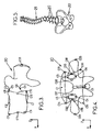
- Each of these images generally comprises several predetermined objects to be examined, for example vertebrae 20 such as that shown schematically on the figure 2 .
- the microcomputer 17 has in memory a three-dimensional generic model which corresponds to an average form of the object in question, which generic model is prepared in advance by statistical methods by analyzing a lot of similar objects.
- the practitioner may, for example, indicate to the microcomputer, in particular by means of the keyboard 18 or the mouse, the type of each object to be examined visible on the microcomputer 17. said images, so that the microcomputer 17 determines the generic model corresponding to this object.
- the generic models used could also be constituted by models previously made by medical imaging on the patient: in this case, the method according to the invention can allow for example to follow the subsequent evolution of the patient by simpler means , less expensive and emitting less radiation than conventional three-dimensional imaging means.
- These coordinates can be expressed for example in a local repository X, Y, Z.
- the Z axis corresponds to the "axial" direction of the spine
- the X axis is determined so as to define with the Z axis the anteroposterior plane of the vertebra 20, the Y axis being perpendicular to the X, Z axes mentioned above.
- the origin O of the reference frame X, Y, Z is disposed in the middle of the two axial end faces of the main "tubular" portion of the vertebra, the origin O being furthermore positioned so that the Z axis crosses the upper axial face of the main part of the vertebra at a marker C1 such that the distance from this marker C1 to the front end C7 of said axial face is equal to about 2/3 of the total distance between the front ends C7 and C8 rear of the anteroposterior section of said upper axial face.
- the practitioner identifies these different control marks for each object to be examined (for example the vertebrae and the pelvis) on each radiographic image, for example by "marking" these markers on the screen 19 by selection by means of the mouse and / or of the keyboard.
- the two images are calibrated, so as to accurately measure the position of each marker of these images in a common repository.
- the position of the corresponding stereo control marks C1-C6 is directly calculated from the measurement of the position of these points on the two images.
- x i is a predetermined stiffness coefficient of the fictitious spring of index i
- x i, 0 is the length of the notional spring of index i in the undeformed generic model
- x i is the notional spring length of index i in the deformed generic model.
- the three-dimensional shape of a model representing the vertebra 20 of the patient is calculated, the calculated model being obtained by deforming the generic model so as to maintain the coincidence of the control points of the deformed generic model with the previously determined spatial position. control points and so that said calculated model follows a form as close as possible to an isometry of the generic model, this time working on all generic model points.
- obtaining the three-dimensional model of each object to be examined can be obtained by the known method of kriging ("krigirg").
- the microcomputer 17 can assemble all the three-dimensional models of the different objects to be examined, depending on the position of these different models in an absolute reference common to all. these objects, so as to obtain a three-dimensional model comprising, for example, the entire spine 21 of the patient and the pelvis 22 of this patient, as shown in FIG. figure 5 .
- this three-dimensional model can be presented on the screen 19 of the microcomputer, or printed, under the desired viewing angle.
- This overall model can also be set in motion on the screen according to the practitioner's commands.
- the practitioner thus has an effective examination tool that can be used for imaging any part, in particular bone or cartilaginous parts of the human or animal body, and useful in particular for the diagnosis of scoliosis. or for pre- or post-operative follow-up during surgical procedures.
- the radiographic device 1 could, if necessary, be adapted for examination of a lying patient, which may be indispensable in the field of trauma.
- the patient P would be lying on a support table, the ionizing radiation beams 10, 16 would each be in a vertical plane, and the sources 5, 11 would move horizontally with the detectors 6, 12.
- the radiographic device 1 can also be used in two-dimensional radiography, in addition to its use in three-dimensional imaging.
Description
La présente invention est relative aux procédés et dispositifs d'imagerie radiographique pour la reconstruction tridimensionnelle à faible dose d'irradiation.The present invention relates to radiographic imaging methods and devices for three-dimensional low dose radiation reconstruction.
Plus particulièrement, l'invention concerne un procédé d'imagerie radiographique pour la reconstruction tridimensionnelle à faible dose d'irradiation, adapté pour calculer un modèle à trois dimensions d'au moins un objet prédéterminé à observer dans un champ d'observation, ce procédé comprenant les étapes suivantes :
- (a) prendre au moins deux images radiographiques à deux dimensions du champ d'observation, respectivement selon deux directions de prise de vue non parallèles,
- (b) repérer, sur chaque image radiographique, des repères de contrôle appartenant audit objet à observer,
- (c) déterminer une position géométrique de chaque repère de contrôle dans un référentiel à trois dimensions,
- (d) calculer la forme à trois dimensions d'un modèle représentant ledit objet à partir d'un modèle générique prédéterminé correspondant audit objet, ce modèle générique comportant des repères qui correspondent aux repères de contrôle identifiés sur les images radiographiques, le modèle calculé étant obtenu par déformation du modèle générique de façon que ledit modèle calculé suive une forme la plus proche possible d'une isométrie du modèle générique tout en maintenant en coïncidence les repères du modèle générique déformé avec les repères de contrôle reconstruits à l'étape (c).
- (a) taking at least two two-dimensional X-ray images of the field of view, respectively in two non-parallel directions of view,
- (b) locating, on each radiographic image, control marks belonging to said object to be observed,
- (c) determining a geometric position of each control mark in a three-dimensional repository,
- (d) calculating the three-dimensional shape of a model representing said object from a predetermined generic model corresponding to said object, said generic model having markers that correspond to the control markers identified on the radiographic images, the calculated model being obtained by deforming the generic model so that said calculated model follows a shape as close as possible to an isometry of the generic model while keeping in coincidence the references of the deformed generic model with the control references reconstructed in step (c) .
Des procédés de reconstruction en trois dimensions du type susmentionné ont été divulgués notamment par Abdel-
Dans ces procédés, tous les repères de contrôle sont des points de contrôle stéréo-correspondants et au cours de l'étape (b), on positionne ces repères dans l'espace au moyen d'un algorithme dit "transformation linéaire directe" (DLT), utilisé notamment par
Ces procédés connus présentent l'avantage de permettre la réalisation d'un modèle tridimensionnel du ou des objets à observer, tout en permettant de réduire l'émission de rayonnements ionisants vers le champ d'observation par rapport à une information tridimensionnelle basée sur la reconstruction de coupes scanner telles que pratiquées dans les instrument actuels. Le modèle tridimensionnel peut ensuite être affiché sous différents angles de vue, par exemple sur un écran d'ordinateur.These known methods have the advantage of making it possible to produce a three-dimensional model of the object or objects to be observed, while at the same time making it possible to reduce the emission of ionizing radiation towards the field of view with respect to a three-dimensional information based on the reconstruction. scanner cuts as practiced in the current instruments. The three-dimensional model can then be displayed from different viewing angles, for example on a computer screen.
Mais ces procédés souffrent d'un manque de précision et sont mal adaptés pour examiner convenablement un champ d'observation étendu tel que par exemple l'ensemble de la colonne vertébrale d'un patient.But these processes suffer from a lack of accuracy and are poorly adapted to properly examine an extended field of view such as for example the entire spine of a patient.
Par ailleurs,
Ce procédé n'est toutefois pas adapté pour une utilisation médicale, où il est nécessaire d'avoir une plus grande facilité de mise en oeuvre, une meilleure précision notamment sur des champs d'observation étendus, et une plus grande rapidité de mise en oeuvre.This method is however not suitable for medical use, where it is necessary to have greater ease of implementation, better accuracy especially on extended fields of observation, and greater speed of implementation .
La présente invention a notamment pour but de pallier ces inconvénients.The present invention is intended to overcome these disadvantages.
A cet effet, selon l'invention, un procédé du genre en question est caractérisé en ce qu'au cours de l'étape (a), les deux images radiographiques sont prises simultanément, par balayage, en déplaçant en synchronisme, dans une même direction de translation non parallèle aux directions de prises de vues, au moins une source radioactive émettant deux faisceaux de rayons ionisants respectivement dans les deux directions de prise de vue.For this purpose, according to the invention, a method of the kind in question is characterized in that during step (a), the two radiographic images are taken simultaneously, by scanning, by moving in synchronism, in the same direction. translation direction not parallel to the shooting directions, at least one radioactive source emitting two beams of ionizing radiation respectively in the two directions of shooting.
Le champ d'observation mentionné ci-dessus peut comprendre notamment le rachis, le bassin, ou encore le genou d'un patient, ou plus généralement être constitué par tout ou partie du squelette du patient. Dans ces différents cas, les objets à observer peuvent être constitués notamment par les os du patient compris dans le champ d'observation ainsi que la durée des opérations de prise de vue.The field of observation mentioned above may include the spine, the pelvis, or the knee of a patient, or more generally be constituted by all or part of the skeleton of the patient. In these different cases, the objects to be observed may consist in particular of the bones of the patient included in the field of view and the duration of the shooting operations.
Grâce aux dispositions susmentionnées, on obtient une bonne précision de la reconstruction à trois dimensions, y compris pour des champs d'observation étendus, et ce en limitant la dose de rayonnements émise vers le champ d'observation.Thanks to the above provisions, we obtain a good accuracy of the three-dimensional reconstruction, including for extended fields of observation, and this by limiting the dose of radiation emitted towards the field of observation.
Cette précision est obtenue grâce à la simultanéité des deux prises de vues, et grâce à la prise de vue par balayage qui améliore la précision dans la direction du balayage notamment pour les champs d'observation étendus.This precision is obtained thanks to the simultaneity of the two shots, and thanks to the scanning shot which improves the precision in the direction of the scan notably for the extended fields of observation.
Dans des modes de réalisation préférés du procédé selon l'invention, on peut éventuellement avoir recours en cutre à l'une et/ou à l'autre des dispositions suivantes :
- au cours de l'étape (b), certains des repères de contrôle identifiés sont des repères de contrôle non stéréo-correspondants visibles et identifiés sur une seule image, et au cours de l'étape (c), la position géométrique de chaque repère de contrôle non stéréo-correspondant dans le référentiel à trois dimensions est estimée à partir du modèle générique, en déplacant les repères correspondant aux repères de contrôle non stéréo-correspondants du modèle générique chacun sur une droite joignant :
- · d'une part, la source radioactive à l'origine de l'image radiographique dans laquelle une projection de ce repère de contrôle non stéréo-correspondant est visible et identifiable (la source radioactive étant positionnée sur l'emplacement de sa trajectoire qui correspond à la prise d'image où est visible ledit repère de contrôle),
- · et d'autre part, ladite projection de ce repère sur l'image radiographique,
- au cours de l'étape (c), on minimise la valeur de la somme quadratique :

- au cours de l'étape (b), certains des repères de contrôle identifiés sont des repères de contrôle stéréo-correspondants visibles et identifiés sur les deux images, et au cours de l'étape (c), la position géométrique des repères de contrôle stéréo-correspondants est directement calculée à partir de mesures de position des projections de ces repères sur les deux images ;
- au cours de l'étape (b), on repère sur chaque image radiographique des lignes de contour correspondant à des limites de l'objet observé et/ou à des lignes de plus grande densité optique à l'intérieur desdites limites, ces lignes de contour comprenant des projections des repères de contrôle sur les images radiographiques ;
- au cours de l'étape (c), on détermine des repères du modèle générique correspondant aux repères de contrôle, lesdits repères du modèle générique comprenant des portions dudit modèle générique qui se présentent tangentiellement par rapport aux rayons issus des sources radioactives et ayant généré les images radiographiques ;
- l'étape (c) comporte les sous-étapes suivantes :
- (c1) créer un modèle générique recalé en adaptant la taille du modèle générique et la position de ce modèle générique dans le référentiel, pour que les projections respectives du modèle générique recalé à partir des deux sources radioactives correspondent sensiblement aux deux images radiographiques,
- (c2) sélectionner des repères du modèle genérique dont les projections sur au moins une des images radiographiques à partir de la source radioactive correspondante, sont les plus proches des lignes de contour repérées au cours de l'étape (b),
- (c3) définir une surface enveloppe formée par des rayons issus de chaque source radioactive et ayant contribué à générer lesdites lignes de contour des images radiographiques,
- (c4) déterminer certains repères du modèle générique recalé correspondant à des surfaces dudit modèle générique recalé, qui sont tangentes auxdites surfaces enveloppes, les repères du modèle générique recalé ainsi déterminés correspondant aux repères de contrôle,
- (c5) et déterminer la position géométrique de chaque repère de contrôle par projection du repère correspondant du modèle générique recalé sur la surface enveloppe correspondante ;
- les deux directions de prise de vue sont perpendiculaires l'une à l'autre ;
- on fait émettre par chacune des sources radioactives un faisceau de rayonnements ionisants dans un plan perpendiculaire à la direction de translation ;
- les deux faisceaux de rayons ionisants sont émis respectivement par deux sources radioactives.
- during step (b), some of the identified control markers are non-stereo-corresponding control markers visible and identified on a single image, and in step (c), the geometric position of each mark non-stereo-matching control in the three-dimensional repository is estimated from the generic model, by moving the markers corresponding to the non-stereo-corresponding control markers of the generic model each on a line joining:
- On the one hand, the radioactive source at the origin of the radiographic image in which a projection of this non-stereo-corresponding control mark is visible and identifiable (the radioactive source being positioned on the location of its corresponding trajectory) at the image pickup where is visible said control mark),
- · And on the other hand, said projection of this marker on the radiographic image,
- during step (c), the value of the quadratic sum is minimized:
- during step (b), some of the identified control marks are corresponding stereo-corresponding control markings identified on the two images, and in step (c), the geometric position of the control marks Stereo-matching is directly calculated from position measurements projections of these landmarks on both images;
- during step (b), each radiographic image is marked with contour lines corresponding to the limits of the object observed and / or to lines of greater optical density within said limits, these lines of contour including projections of control marks on X-ray images;
- during step (c), markers of the generic model corresponding to the control marks are determined, said references of the generic model comprising portions of said generic model that are tangential with respect to the rays originating from the radioactive sources and having generated the radiographic images;
- step (c) comprises the following substeps:
- (c1) creating a generic model recaled by adapting the size of the generic model and the position of this generic model in the repository, so that the respective projections of the generic model recalibrated from the two radioactive sources substantially correspond to the two radiographic images,
- (c2) selecting markers of the generic model whose projections on at least one of the radiographic images from the corresponding radioactive source are closest to the contour lines identified in step (b),
- (c3) defining an envelope surface formed by rays from each radioactive source and having contributed to generating said contour lines of the radiographic images,
- (c4) determining certain markers of the reset generic model corresponding to surfaces of said reset generic model, which are tangent to said envelope surfaces, the pins of the reset generic model thus determined corresponding to the control marks,
- (c5) and determining the geometric position of each control mark by projecting the corresponding reference of the generic model recaled on the corresponding envelope surface;
- the two directions of view are perpendicular to each other;
- each radioactive source emits a beam of ionizing radiation in a plane perpendicular to the direction of translation;
- the two beams of ionizing radiation are emitted respectively by two radioactive sources.
Par ailleurs, l'invention a également pour objet un dispositif d'imagerie radiographie pour la mise en oeuvre d'un procédé tel que défini ci-dessus, ce dispositif comportant :
- des moyens d'émission de rayons ionisants comprenant au moins une source radioactive, ces moyens d'émission étant adaptés pour émettre respectivement deux faisceaux de rayonnements ionisants vers un champ d'observation contenant au moins un objet à observer, dans deux directions de prise de vue non parallèles, lesdits moyens d'émission étant déplaçables simultanément selon une direction de translation non parallèle aux directions de prise de vue,
- au moins deux dispositifs de détection disposes respectivement face aux deux faisceaux de rayons ionisants, au-delà du champ d'observation, pour mesurer les rayonnements ionisants ayant traversé ledit champ d'observation, ces deux dispositifs de détection étant déplaçables en synchronisme avec les moyens d'émission dans ladite direction de translation,
- des moyens pour prendre simultanément au moins deux images radiographiques à deux dimensions du champ d'observation, par balayage simultané du champ d'observation avec les sources radioactives et les détecteurs dans la direction de translation,
- des moyens d'identification pour identifier, sur chaque image radiographique, des repères de contrôle prédéterminés appartenant audit objet à observer,
- des premiers moyens de reconstruction pour déterminer une position géométrique de chaque repère de contrôle dans un référentiel à trois dimensions, à partir d'un modèle générique prédéterminé correspondant audit objet, ce modèle générique comportant des repères qui correspondent aux repères de contrôle identifiés sur les images radiographiques,
- et des seconds moyens de reconstruction pour calculer la forme à trois dimensions d'un modèle représentant ledit objet à partir du modèle générique, lesdits seconds moyens de reconstruction étant adaptés pour déterminer le modèle calculé par déformation du modèle générique de façon que ledit modèle calculé suive une forme la plus proche possible d'une isométrie du modèle générique tout en maintenant en coïncidence les repères du modèle générique déformé avec les repères de contrôle reconstruits par les premiers moyens de reconstruction.
- ionizing radiation emission means comprising at least one radioactive source, said emission means being adapted to respectively emit two beams of ionizing radiation to an observation field containing at least one object to be observed, in two directions of non-parallel views, transmission means being movable simultaneously in a translation direction not parallel to the shooting directions,
- at least two detection devices arranged respectively opposite the two beams of ionizing rays, beyond the field of view, for measuring the ionizing radiation having passed through said field of observation, these two detection devices being movable in synchronism with the means in said translational direction,
- means for simultaneously taking at least two two-dimensional X-ray images of the field of view, by simultaneous scanning of the field of view with the radioactive sources and the detectors in the direction of translation,
- identification means for identifying, on each radiographic image, predetermined control marks belonging to said object to be observed,
- first reconstruction means for determining a geometric position of each control mark in a three-dimensional repository, from a predetermined generic model corresponding to said object, this generic model comprising markers which correspond to the control marks identified on the images radiographic,
- and second reconstruction means for calculating the three-dimensional shape of a model representing said object from the generic model, said second reconstruction means being adapted to determine the model calculated by deformation of the generic model so that said calculated model follows a form as close as possible to an isometry of the generic model while maintaining in coincidence the references of the deformed generic model with the control marks reconstructed by the first reconstruction means.
Dans des modes de réalisation préférés du dispositif selon l'invention, on peut éventuellement avoir recours en outre à l'une et/cu à l'autre des dispositions suivantes :
- les moyens d'identification sont adaptés pour identifier au moins certains repères de contrôle visibles et identifiables sur une seule image radiographique dits repères de contrôle non stéréo-correspondants et les premiers moyens de reconstruction sont adaptés pour estimer la position géométrique des repères de contrôle non stéréo-correspondants en déplaçant les repères du modèle générique correspondant aux repères de contrôle non stéréo-correspondants, chacun sur une droite joignant :
- . d'une part, la source radioactive à l'origine de l'image radiographique où une projection de ce repère de contrôle non stéréo-correspondant est visible et identifiable,
- . et d'autre part, ladite projection de ce repère sur l'image radiographique,
- les moyens d'identification sont adaptés pour identifier sur les deux images des repères de contrôle qui sont visibles et identifiables sur lesdites deux images, dits repères de contrôle stéréo-correspondants, et les premiers moyens de reconstruction sont adaptés pour déterminer la position géométrique des repères de contrôle stéréo-correspondants par calcul à partir de mesures de position des projections de ces repères sur les deux images ;
- chaque détecteur comprend une ligne de cellules de détection perpendiculaire à la direction de translation, les faisceaux de rayonnements ionisants étant perpendiculaires à ladite la direction de translation ;
- les moyens d'émission et les détecteurs sont déplaçables sur une distance de balayage d'au moins 7C cm ;
- les moyens d'émission comprennent deux sources radioactives à l'origine respectivement des deux faisceaux de rayons ionisants.
- the identification means are adapted to identify at least some visible and identifiable control marks on a single radiographic image called non-stereo-corresponding control marks and the first reconstruction means are adapted to estimate the geometric position of the non-stereo control markers corresponding by moving the markers of the generic model corresponding to the non-stereo-corresponding control markers, each on a line joining:
- . on the one hand, the radioactive source at the origin of the radiographic image where a projection of this non-stereo-corresponding control mark is visible and identifiable,
- . and on the other hand, said projection of this marker on the radiographic image,
- the identification means are adapted to identify on the two images control marks which are visible and identifiable on said two images, called stereo-corresponding control marks, and the first reconstruction means are adapted to determine the geometric position of the markers stereo-corresponding control by calculation from position measurements projections of these marks on the two images;
- each detector comprises a line of detection cells perpendicular to the direction of translation, the beams of ionizing radiation being perpendicular to said direction of translation;
- the transmitting means and the detectors are movable over a scanning distance of at least 7 cm;
- the transmitting means comprise two radioactive sources at the origin respectively of the two beams of ionizing radiation.
D'autres caractéristiques et avantages de l'invention apparaitront au cours de la description suivante d'une de ses formes de réalisation, donnée à titre d'exemple non limitatif, en regard des dessins joints.Other features and advantages of the invention will become apparent from the following description of one of its embodiments, given by way of non-limiting example, with reference to the accompanying drawings.
Sur les dessins :
- la
figure 1 est une vue schématique d'un appareil de radiographie selon une forme de réalisation de l'invention, permettant d'effectuer simultanément une prise de vue de face et une prise de vue de profil du patient, - la
figure 2 est une vue schématique en perspective d'une vertèbre d'un patient examiné au moyen de l'appareil de lafigure 1 , - les
figures 3 et 4 sont respectivement des vues de profil et de face de la vertèbre de lafigure 2 , schématisant une partie des vues de profil et de face obtenues au moyen de l'appareil de lafigure 1 , - et la
figure 5 est une vue en perspective représentant un modèle à trois dimensions de la colonne vertébrale et du bassin du patient examiné au moyen de l'appareil de lafigure 1 , ce modèle étant calculé à partir des vues de profil et de face prises au moyen de l'appareil de lafigure 1 .
- the
figure 1 is a schematic view of an X-ray apparatus according to one embodiment of the invention, making it possible to simultaneously take a front view and a side view of the patient, - the
figure 2 is a schematic view in perspective of a vertebra of a patient examined by means of the device of thefigure 1 , - the
Figures 3 and 4 are respectively side and side views of the vertebra of thefigure 2 , schematizing a part of the profile and front views obtained by means of the apparatus of thefigure 1 , - and the
figure 5 is a perspective view showing a three-dimensional model of the spine and pelvis of the patient examined using the device of thefigure 1 , this model being calculated from the profile and front views taken by means of the apparatus of thefigure 1 .
Sur les différentes figures, les mêmes références désignent des éléments identiques ou similaires.In the different figures, the same references designate identical or similar elements.
La
Ce bâti entoure un champ d'observation 4 dans lequel peut prendre place un patient P debout. On peut ainsi observer la position des os du squelette de ce patient en station debout, ce qui est essentiel notamment pour les patients atteints de scoliose.This frame surrounds an observation field 4 in which a patient P can stand. It is thus possible to observe the position of the bones of the skeleton of this patient while standing, which is essential in particular for patients with scoliosis.
Le bâti mobile 2 porte une première source radioactive 5 et un premier détecteur 6 qui est disposé face à la source 5 au-delà du champ 4, et qui comporte une ligne horizontale 6a de cellules de détection. Le détecteur 6 peut par exemple être un détecteur gazeux sensible aux basses doses de rayonnements, par exemple tel que décrit dans le document
La source radioactive 5 est adaptée pour émettre des rayons ionisants, notamment des rayons X, dans une direction de prise de vue 7 antéro-postérieure par rapport au patient P, en traversant une fente horizontale 8 ménagée dans un réticule 9 tel qu'une plaque métallique, pour générer un faisceau horizontal 10 de rayonnements ionisants dans le champ d'observation 4.The radioactive source 5 is adapted to emit ionizing rays, in particular X-rays, in an anteroposterior direction of shooting with respect to the patient P, by passing through a horizontal slit 8 formed in a reticle 9 such as a plate metal, to generate a horizontal beam 10 of ionizing radiation in the field of view 4.
Par ailleurs, le bâti mobile 2 porte également une deuxième source radioactive 11 similaire à la source 5 et un deuxième détecteur 12 similaire au détecteur 6, qui est disposé face à la source 11 au-delà du champ 4, et qui comporte une ligne horizontale 12a de cellules de détection.Furthermore, the
La source radioactive 11 est adaptée pour émettre des rayons ionisants, dans une direction de prise de vue latérale 13 par rapport au patient P, en traversant une fente horizontale 14 ménagée dans un réticule 15 tel qu'une plaque métallique, pour générer un faisceau horizontal 16 de rayonnements ionisants dans le champ d'observation 4.The
On notera que les sources radioactives et les détecteurs pourraient le cas échéant être en nombre supérieur à 2, et que les directions de prises de vue de ces différentes sources radioactives pourraient le cas échéant ne pas être perpendiculaires entre elles ni horizontales.It should be noted that the radioactive sources and the detectors could, if necessary, be in a number greater than 2, and that the directions of shooting of these different radioactive sources could if need be not perpendicular to each other or horizontal.
Les deux détecteurs 6, 12 sont reliés à un micro-ordinateur 17 ou autre système électronique de commande, équipé :
- d'une interface d'entrée comprenant au moins un clavier et généralement une souris (non représentée),
- et d'une interface de sortie comprenant au moins
un écran 19 et généralement une imprimante (non représentée).
- an input interface comprising at least one keyboard and generally a mouse (not shown),
- and an output interface comprising at least one
screen 19 and generally a printer (not shown).
Le micro-ordinateur 17 peut également être relié aux moyens d'entraînement motorisés (non représentés) contenus dans les guides 3 et aux sources 5, 11, de façon à commander le déplacement vertical du bâti 2 et l'émission des rayonnements ionisants.The
Le dispositif qui vient d'être décrit fonctionne comme suit.The device that has just been described operates as follows.
Au moyen du micro-ordinateur 17, on fait d'abord prendre deux images radiographiques du patient P, en faisant balayer le champ d'observation 4 par les faisceaux 1C, 16 de rayonnements ionisants sur la hauteur correspondant à la zone du patient à observer, par exemple le rachis et le bassin, voire l'ensemble du squelette (à cet effet, le bâti est de préférence déplaçable sur une hauteur d'au moins 70 cm, voire supérieure à 1 m).Using the
Au cours de ce mouvement, on enregistre dans la mémoire du micro-ordinateur 17 deux images radiographiques numériques, par exemple respectivement antéro-postérieure et latérale de la partie examinée du patient, lesquelles images peuvent être visualisées sur l'écran 19 du micro-ordinateur.During this movement, two digital radiographic images are recorded in the memory of the
Chacune de ces images comprend généralement plusieurs objets prédéterminés à examiner, par exemple des vertèbres 20 telles que celle représentée schématiquement sur la
Pour chacun de ces objets à examiner, le micro-ordinateur 17 a en mémoire un modèle générique à trois dimensions qui correspond à une forme moyenne de l'objet en question, lequel modèle générique est élaboré à l'avance par des méthodes statistiques en analysant un grand nombre d'objets similaires.For each of these objects to be examined, the
Lors de l'affichage des images radiographiques sur l'écran 19 du micro-ordinateur 17, le praticien peut par exemple indiquer au micro-ordinateur, notamment au moyen du clavier 18 ou de la souris, le type de chaque objet à examiner visible sur lesdites images, de façon que le micro-ordinateur 17 détermine le modèle générique correspondant à cet objet.When the radiographic images are displayed on the
Par ailleurs, les modèles génériques utilisés pourraient également être constitués par des modèles préalablement réalisés par imagerie médicale sur le patient : dans ce cas, le procédé selon l'invention peut permettre par exemple de suivre l'évolution ultérieure du patient par des moyens plus simples, moins coûteux et émettant moins de radiations que les moyens d'imagerie tridimensionnelle classiques.Furthermore, the generic models used could also be constituted by models previously made by medical imaging on the patient: in this case, the method according to the invention can allow for example to follow the subsequent evolution of the patient by simpler means , less expensive and emitting less radiation than conventional three-dimensional imaging means.
Le modèle générique de chaque objet, par exemple de chaque vertèbre 20 d'un squelette humain, comprend :
- les coordonnées d'une pluralité de repères de contrôle, notamment des points correspondant à des repères singuliers de cette vertèbre,
- et les coordonnées d'un grand nombre d'autres repères de l'objet en question, par exemple au nombre d'environ 200 ou plus.
- the coordinates of a plurality of control marks, in particular points corresponding to singular marks of this vertebra,
- and the coordinates of a large number of other landmarks of the object in question, for example about 200 or more.
Ces coordonnées peuvent être exprimées par exemple dans un référentiel local X, Y, Z. Dans l'exemple considéré, l'axe Z correspond à la direction "axiale" de la colonne vertébrale, l'axe X est déterminé de façon à définir avec l'axe Z le plan antéro-postérieur de la vertèbre 20, l'axe Y étant perpendiculaire aux axes X, Z susmentionnés. De plus, l'origine O du référentiel X, Y, Z est disposée au milieu des deux faces d'extrémité axiales de la partie principale "tubulaire" de la vertèbre, l'origine O étant par ailleurs positionnée pour que l'axe Z traverse la face axiale supérieure de la partie principale de la vertèbre en un repère C1 tel que la distance de ce repère C1 à l'extrémité avant C7 de ladite face axiale soit égale à environ 2/3 de la distance totale entre les extrémités avant C7 et arrière C8 de la section antéro-postérieure de ladite face axiale supérieure.These coordinates can be expressed for example in a local repository X, Y, Z. In the example considered, the Z axis corresponds to the "axial" direction of the spine, the X axis is determined so as to define with the Z axis the anteroposterior plane of the
Les différents repères de contrôle C1-C25 susmentionnés se répartissent en deux catégories :
- des repères de contrôle "stéréo-correspondants" C1-C6, visibles et identifiables à la fois sur l'image radiographique latérale et sur l'image antéro-postérieure, ces repères étant au nombre de 6 dans l'exemple considéré (voir
figures 3 et 4 ), - et des repères de contrôle "non stéréo-correspondants" C7-C25, visibles et identifiables sur une seule image, ces repères étant au nombre de 19 dans l'exemple considéré.
- C1-C6 "stereo-corresponding" control markers, visible and identifiable both on the lateral radiographic image and on the anteroposterior image, these reference marks being 6 in the example under consideration (see
Figures 3 and 4 ) - and C7-C25 "non-stereo-corresponding" control markers, visible and identifiable in a single image, these references being 19 in the example in question.
Le praticien identifie ces différents repères de contrôle pour chaque objet à examiner (par exemple les vertèbres et le bassin) sur chaque image radiographique, par exemple en "marquant" ces repères à l'écran 19 par sélection au moyen de la souris et/ou du clavier. De plus, les deux images sont calibrées, de façon à pouvoir mesurer précisément la position de chaque repère de ces images dans un référentiel commun.The practitioner identifies these different control marks for each object to be examined (for example the vertebrae and the pelvis) on each radiographic image, for example by "marking" these markers on the
Ensuite, on détermine une position géométrique de chaque repère de contrôle de chaque objet, dans un référentiel à trois dimensions, par exemple le référentiel X, Y, Z susmentionné ou un référentiel commun à l'ensemble des objets à examiner.Next, we determine a geometric position of each control mark of each object, in a three-dimensional repository, for example the aforementioned X, Y, Z repository or a repository common to all the objects to be examined.
La position des repères de contrôle stéréo-correspondants C1-C6 est directement calculée à partir de la mesure de la position de ces points sur les deux images.The position of the corresponding stereo control marks C1-C6 is directly calculated from the measurement of the position of these points on the two images.
De plus, la position géométrique de chaque repère de contrôle non stéréo-correspondant C7-C25 dans le référentiel à trois dimensions est estimée à partir du modèle générique, en déplaçant chaque repère de contrôle stéréo-correspondant C1-C6 du modèle générique jusqu'à sa position mesurée, et en déplaçant les repères de contrôle non stéréo-correspondants C7-C25 du modèle générique, chacun sur une droite joignant :
- . d'une part, la source radioactive 5, 6 à l'origine de l'image radiographique où une projection de ce repère de contrôle non stéréo-correspondant est visible et identifiable,
- . et d'autre part, ladite projection de ce repère sur l'image radiographique,
- . on the one hand, the
radioactive source 5, 6 at the origin of the radiographic image where a projection of this non-stereo-corresponding control mark is visible and identifiable, - . and on the other hand, said projection of this marker on the radiographic image,
En particulier, on peut minimiser ladite déformation en minimisant (par exemple au moyen d'une méthode de gradient) la valeur de la somme quadratique : 
ou plus généralement 
où λ est un coefficient constant prédéterminé, m est un nombre entier non nul représentant un nombre de ressorts fictifs qui relient chaque repère de contrôle du modèle générique à d'autres repères de contrôle, k. est un coefficient de raideur prédéterminé du ressort fictif d'indice i, xi,0 est la longueur du ressort fictif d'indice i dans le modèle générique non déformé, et xi est la longueur au ressort fictif d'indice i dans le modèle générique déformé.In particular, one can minimize said deformation by minimizing (for example by means of a gradient method) the value of the quadratic sum:
or more generally
where λ is a predetermined constant coefficient, m is a non-zero integer representing a number of dummy springs that connect each control mark of the generic model to other control marks, k. is a predetermined stiffness coefficient of the fictitious spring of index i, x i, 0 is the length of the notional spring of index i in the undeformed generic model, and x i is the notional spring length of index i in the deformed generic model.
Enfin, on calcule la forme à trois dimensions d'un modèle représentant la vertèbre 20 du patient, le modèle calculé étant obtenu par déformation du modèle générique de façon à maintenir la coïncidence des points de contrôle du modèle générique déformé avec la position spatiale précédemment déterminée des points de contrôle et de façon que ledit modèle calculé suive une forme la plus proche possible d'une isométrie du modèle générique, en travaillant cette fois sur l'ensemble des points de modèle générique.Finally, the three-dimensional shape of a model representing the
En particulier, l'obtention du modèle à trois dimensions de chaque objet à examiner peut être obtenu par le procédé connu de krigeage ("krigirg").In particular, obtaining the three-dimensional model of each object to be examined can be obtained by the known method of kriging ("krigirg").
Après le calcul du modèle à trois dimensions des différents objets à examiner, le micro-ordinateur 17 peut assembler la totalité des modèles à trois dimensions des différents objets à examiner, en fonction de la position de ces différents modèles dans un référentiel absolu commun à tous ces objets, de façon à obtenir un modèle à trois dimensions comprenant par exemple l'ensemble du rachis 21 du patient et le bassin 22 de ce patient, comme représenté sur la
Une fois élaboré, ce modèle à trois dimensions peut être présenté sur l'écran 19 du micro-ordinateur, ou imprimé, sous l'angle de vision voulu. Ce modèle d'ensemble peut également être mis en mouvement à l'écran en fonction des commandes du praticien.Once developed, this three-dimensional model can be presented on the
Le praticien dispose ainsi d'un outil efficace d'examen pouvant servir à l'imagerie de toute partie notamment osseuse ou cartilagineuse du corps humain ou animal, et utile notamment pour le diagnostic des scolioses ou pour le suivi pré ou post-opératoire lors d'interventions chirurgicales.The practitioner thus has an effective examination tool that can be used for imaging any part, in particular bone or cartilaginous parts of the human or animal body, and useful in particular for the diagnosis of scoliosis. or for pre- or post-operative follow-up during surgical procedures.
Bien entendu, on peut également calculer certains indices cliniques prédéterminés liés soit à la géométrie de l'ensemble examiné, soit le cas échéant à la composition ou la densité des objets à examiner, estimées à partir des images radiographiques (cas de l'ostéoporose par exemple).Of course, it is also possible to calculate certain predetermined clinical indices related either to the geometry of the assembly examined, or, if appropriate, to the composition or the density of the objects to be examined, estimated from the radiographic images (case of osteoporosis by example).
On notera que le dispositif radiographique 1 pourrait le cas échéant être adapté pour l'examen d'un patient couché, ce qui peut s'avérer indispensable dans le domaine de la traumatologie. Dans ce cas, le patient P serait couché sur une table support, les faisceaux de rayons ionisants 10, 16 seraient chacun dans un plan vertical, et les sources 5, 11 se déplaceraient horizontalement avec les détecteurs 6, 12.It will be noted that the
Par ailleurs, il va de soi que dans tous les cas, le dispositif radiographique 1 peut être utilisé également en radiographie à deux dimensions, en plus de son utilisation en imagerie tridimensionnelle.Moreover, it goes without saying that in all cases, the
On notera que le dispositif selon l'invention pourrait le cas échéant être utilisé dans des applications de radiologie non médicale.It will be noted that the device according to the invention could if necessary be used in non-medical radiology applications.
Par ailleurs, au lieu d'utiliser des repères de contrôle C1-C25 définis à l'avance sur chaque modèle générique, il serait possible de déterminer et de positionner dans l'espace les repères de contrôle à partir de lignes de contour de l'objet à observer visibles sur l'une ou l'autre des deux images radiographiques.Moreover, instead of using C1-C25 control marks defined in advance on each generic model, it would be possible to determine and position in the space the control marks from contour lines of the object to be observed visible on one or the other of the two radiographic images.
A cet effet, on pourrait en particulier procéder comme suit :
- on repère sur chaque image radiographique des lignes de contour correspondant à des limites de l'objet observé et/ou à des lignes de plus grande densité optique à l'intérieur desdites limites,
- on crée un modèle générique recalé en adaptant la taille du modèle générique et la position de ce modèle générique dans le référentiel X, Y, Z pour que les projections respectives du modèle générique recalé à partir des deux sources radioactives 5, 11 correspondent sensiblement aux deux images radiographiques,
- on sélectionne des repères du modèle générique dont les projections sur au moins une des images radiographiques à partir de la source radioactive correspondante, sont les plus proches des lignes de contour repérées au cours de l'étape (b),
- on définit une surface enveloppe formée par des rayons issus de chaque source radioactives et ayant contribué à générer lesdites lignes de contour des images radiographiques,
- on détermine certains repères du modèle générique recalé correspondant à des surfaces dudit modèle générique recalé, qui sont tangentes auxdites surfaces enveloppes, les repères du modèle générique recalé ainsi déterminés correspondant aux repères de contrôle,
- on détermine la position géométrique de chaque repère de contrôle par projection dudit repère de contrôle sur la surface enveloppe correspondante,
- puis on procède par exemple comme décrit précédemment pour reconstituer un modèle à trois dimensions de l'ensemble de l'objet à observer, notamment par krigeage.
- on each radiographic image, contour lines corresponding to limits of the observed object and / or lines of greater optical density within said limits are recorded,
- we create a generic model recaled by adapting the size of the generic model and the position of this generic model in the X, Y, Z repository so that the respective projections of the generic model recalibrated from the two
radioactive sources 5, 11 correspond substantially to the two radiographic images,
- markers of the generic model are selected whose projections on at least one of the radiographic images from the corresponding radioactive source are closest to the contour lines identified during step (b),
- defining an envelope surface formed by radii from each radioactive source and having contributed to generating said contour lines of the radiographic images,
- certain markers of the reset generic model corresponding to surfaces of said recalibrated generic model, which are tangent to said envelope surfaces, are determined, the references of the reset generic model thus determined corresponding to the control marks,
- the geometric position of each control mark is determined by projecting said control mark onto the corresponding envelope surface,
- then proceed for example as described above to reconstruct a three-dimensional model of the entire object to be observed, including kriging.
Cn notera enfin qu'il serait possible de générer deux faisceaux ionisants non parallèles au moyen de deux réticules (par exemple deux fentes distinctes mémorisées dans une même plaque métallique) à partir d'une source radioactive unique pour mettre en oeuvre l'invention, en utilisant comme précédemment deux détecteurs disposés face aux deux faisceaux et déplaçables en synchronisme avec la source et les réticules.Finally, it will be noted that it would be possible to generate two non-parallel ionizing beams by means of two reticles (for example two distinct slots stored in the same metal plate) from a single radioactive source to implement the invention, using as before two detectors arranged facing the two beams and movable in synchronism with the source and the reticles.
Claims (16)
- Radiographic imaging method for three-dimensional reconstruction at a low irradiation dose, suitable for calculating a three-dimensional model of at least one pre-determined object (20) to be observed in an observation field (4), this method comprising the following steps:(a) taking at least two two-dimensional radiographic images of the observation field, respectively in two non-parallel shooting directions (7, 13),(b) locating, on each radiographic image, check marks (C1-C25) belonging to said object to be observed,(c) determining a geometric position of each check mark, in a three-dimensional reference frame,(d) calculating the three-dimensional shape of a model representing said object from a pre-determined generic model corresponding to said object, this generic model comprising marks that correspond to the check marks identified on the radiographic images, the calculated model being obtained by deformation of the generic model so that said calculated model follows a shape the closest possible to an isometry of the generic model while keeping the marks of the deformed generic model coinciding with the check marks reconstructed at step (c),characterised in that, during step (a), the two radiographic images are taken simultaneously, by scanning, while moving in synchronism in a same translation direction (3a) not parallel to the shooting directions, at least one radioactive source (5, 11) emitting two beams of ionizing rays (10, 16) respectively in the two shooting directions (7, 13).
- Method according to claim 1, in which:- during step (b), some of the identified check marks, referred to as non-stereocorresponding check marks, are visible and identified only on a single image,- and during step (c), the geometric position of each non-stereocorresponding check mark (C7-C25) in the three-dimensional reference frame is estimated from the generic model, by moving the non-stereocorresponding check marks of the generic model, each on a straight line joining:• on the one hand, the radioactive source (5, 11) at the origin of the radiographic image in which a projection of this non-stereocorresponding check mark is visible and identifiable,• and on the other hand, said projection of this mark on the radiographic image,the non-stereocorresponding check marks (C7-C25) being thus moved to respective positions that minimize the global deformation of the generic model of the object to be observed.
- Method according to claim 2, in which, during step (c), the value of the following quadratic sum is minimized:

where λ is a constant coefficient, m is an integer number of fictional springs connecting each mark (C1-C25) of the generic model to other marks of this model, ki is a predetermined stiffness value of the fictional spring of index i, Xi0 is the length of the fictional spring of index i in the initial generic model, and xi is the length of the fictional spring of index i in the deformed generic model. - Method according to any one of the preceding claims, in which:- during step (b), at least some of the identifiable check marks are stereocorresponding check marks (C1-C6) visible and identified on the two images,- and during step (c), the geometric position of the stereocorresponding check marks (C1-C6) is directly calculated from measurements of the position of the projections of these marks on the two images.
- Method according to claim 1, in which, during step (b), contour lines corresponding to limits of the observed object and/or to lines of greater optical density within said limits are located on each radiographic image, these contour lines comprising projections of the check marks on the radiographic images.
- Method according to claim 5, in which, during step (c), marks of the generic model corresponding to the check marks are determined, said marks of the generic model comprising portions of said generic model that present tangentially with respect to the rays coming from the radioactive sources and having generated the radiographic images.
- Method according to claim 6, in which step (c) comprises the following sub-steps:(c1) creating an adjusted generic model by adapting the size of the generic model andthe position of this generic model in the reference frame, so that the respective projections of the adjusted generic model from the two radioactive sources correspond substantially to the two radiographic images,(c2) selecting marks of the generic model the projections of which on at least one of the radiographic images from the corresponding radioactive source are the closest to the contour lines located during step (b).(c3) defining an envelope surface formed by rays coming from each radioactive source (5, 11) and having contributed to generating said contour lines of the radiographic images,(c4) determining some marks of the adjusted generic model corresponding to surfaces of said adjusted generic model that are tangent to said envelope surfaces, the marks of the adjusted generic model thus determined corresponding to the check marks,(c5) and determining the geometric position of each check mark by projecting the corresponding mark of the adjusted generic model on the corresponding envelope surface.
- Method according to any one of the preceding claims, in which the two shooting directions (7, 13) are perpendicular to each other.
- Method according to claim 8, in which each of the radioactive sources (5, 11) is made to emit a beam of ionizing radiations (10, 16) in a plane perpendicular to the translation direction (3a).
- Method according to any one of the preceding claims, in which the two beams of ionizing rays (10, 16) are emitted respectively by two radioactive sources (5, 11).
- Radiographic imaging device for implementing a method according to any one of the preceding claims, this device comprising:- means (17) for taking at least two two-dimensional radiographic images of the observation field,- identification means (17) for identifying, on each radiographic image, predetermined check marks (C1-C25) belonging to said object to be observed,- first reconstruction means (17) for determining a geometric position of each check mark in a three-dimensional reference frame (X, Y, Z), from a predetermined generic model corresponding to said object, this generic model comprising marks that correspond to the check marks identified on the radiographic images,- and second reconstruction means (17) for calculating the three-dimensional shape of a model representing said object from the generic model, said second reconstruction means being suitable for determining the calculated model by deformation of the generic model so that said calculated model follows a shape the closest possible to an isometry of the generic model while keeping the marks (C1-C25) of the deformed generic model coinciding with the check marks reconstructed by the first reconstruction means,characterised in that the device comprises:- means for emitting ionizing rays comprising at least one radioactive source (5, 11), these emission means being suitable for emitting respectively two beams of ionizing radiations (10, 16) toward an observation field (4) containing at least one object (20) to be observed, in two non-parallel shooting directions (7, 13), said emission means being movable in a translation direction (3a) not parallel to the shooting directions so that the two beams (10, 16) simultaneously scan the observation field,- at least two detection devices (6, 12) disposed respectively facing the two beams of ionizing rays (10, 16), beyond the observation field (4), in order to measure the ionizing radiations that passed through said observation field, these two detection devices being movable in synchronism with the emission means in said translation direction,and in that the means (17) for taking at least two two-dimensional radiographic images of the observation field are means (17) for simultaneously taking at least two two-dimensional radiographic images of the observation field, by simultaneous scanning of the observation field with the emission means (5, 11) and the detectors (6, 12) in the translation direction (3a).
- Device according to claim 11, in which the identification means are suitable for identifying check marks (C7-C25) visible and identifiable on a single radiographic image, referred to as non-stereocorresponding check marks, and the first reconstruction means are suitable for estimating the geometric position of the non-stereocorresponding check marks by moving the non-stereocorresponding marks (C7-C25) of the generic model, each on a straight line joining:- on the one hand, the radioactive source (5, 6) at the origin of the radiographic image where a projection of this non-stereocorresponding check mark is visible and identifiable,- and on the other hand, said projection of this mark on the radiographic image,the first reconstruction means being suitable for thus moving the non-stereocorresponding check marks to respective positions that minimize the global deformation of the generic model of the object to be observed.
- Device according to claim 11 or claim 12, in which the locating means are suitable for locating, on the two images, some of the check marks (C1-C6) that are visible and identifiable on said two images, referred to as "stereocorresponding check marks", and the first reconstruction means are adapted for determining the geometric position of the stereocorresponding check marks by calculation from position measurements of the projections of these marks on the two images.
- Device according to any one of claims 11 to 13, in which each detector (6, 12) comprises a row (6a, 12a) of detection cells perpendicular to the translation direction (3a), the beams of ionizing radiations (10, 16) being perpendicular to said translation direction.
- Device according to any one of claims 11 to 14, in which the emission means (5, 11) and the detectors (6, 12) are movable over a scanning distance of at least 70 cm.
- Device according to any one of claims 11 to 15, in which the emission means comprise two radioactive sources (5, 11) at the origin respectively of the two beams of ionizing rays (10, 11).
Priority Applications (1)
| Application Number | Priority Date | Filing Date | Title |
|---|---|---|---|
| EP11151762.9A EP2309462B1 (en) | 2000-06-23 | 2001-06-11 | Radiographic imaging method and device for three-dimensional reconstruction with low dose of irradiation |
Applications Claiming Priority (2)
| Application Number | Priority Date | Filing Date | Title |
|---|---|---|---|
| FR0008123A FR2810769B1 (en) | 2000-06-23 | 2000-06-23 | RADIOGRAPHIC IMAGING METHOD AND DEVICE FOR THREE-DIMENSIONAL LOW-DOSE IRRADIATION RECONSTITUTION |
| FR0008123 | 2000-06-23 |
Related Child Applications (2)
| Application Number | Title | Priority Date | Filing Date |
|---|---|---|---|
| EP11151762.9A Division EP2309462B1 (en) | 2000-06-23 | 2001-06-11 | Radiographic imaging method and device for three-dimensional reconstruction with low dose of irradiation |
| EP11151762.9 Division-Into | 2011-01-21 |
Publications (2)
| Publication Number | Publication Date |
|---|---|
| EP1168249A1 EP1168249A1 (en) | 2002-01-02 |
| EP1168249B1 true EP1168249B1 (en) | 2011-10-26 |
Family
ID=8851644
Family Applications (2)
| Application Number | Title | Priority Date | Filing Date |
|---|---|---|---|
| EP11151762.9A Expired - Lifetime EP2309462B1 (en) | 2000-06-23 | 2001-06-11 | Radiographic imaging method and device for three-dimensional reconstruction with low dose of irradiation |
| EP01401511A Expired - Lifetime EP1168249B1 (en) | 2000-06-23 | 2001-06-11 | Radiographic imaging method and device for three-dimensional reconstruction with low dose of irradiation |
Family Applications Before (1)
| Application Number | Title | Priority Date | Filing Date |
|---|---|---|---|
| EP11151762.9A Expired - Lifetime EP2309462B1 (en) | 2000-06-23 | 2001-06-11 | Radiographic imaging method and device for three-dimensional reconstruction with low dose of irradiation |
Country Status (2)
| Country | Link |
|---|---|
| EP (2) | EP2309462B1 (en) |
| FR (1) | FR2810769B1 (en) |
Cited By (1)
| Publication number | Priority date | Publication date | Assignee | Title |
|---|---|---|---|---|
| WO2014191790A1 (en) | 2013-05-30 | 2014-12-04 | Eos Imaging | Method for designing a patient specific orthopaedic device |
Families Citing this family (21)
| Publication number | Priority date | Publication date | Assignee | Title |
|---|---|---|---|---|
| US7787932B2 (en) | 2002-04-26 | 2010-08-31 | Brainlab Ag | Planning and navigation assistance using two-dimensionally adapted generic and detected patient data |
| US9958569B2 (en) | 2002-07-23 | 2018-05-01 | Rapiscan Systems, Inc. | Mobile imaging system and method for detection of contraband |
| FR2849241B1 (en) * | 2002-12-20 | 2005-06-24 | Biospace Instr | RADIOGRAPHIC IMAGING METHOD AND DEVICE |
| FR2856170B1 (en) * | 2003-06-10 | 2005-08-26 | Biospace Instr | RADIOGRAPHIC IMAGING METHOD FOR THREE-DIMENSIONAL RECONSTRUCTION, DEVICE AND COMPUTER PROGRAM FOR IMPLEMENTING SAID METHOD |
| US7809109B2 (en) | 2004-04-09 | 2010-10-05 | American Science And Engineering, Inc. | Multiple image collection and synthesis for personnel screening |
| US9119555B2 (en) | 2007-07-04 | 2015-09-01 | Eos Imaging | Method for correcting an acquired medical image and medical imager |
| EP2056255B1 (en) | 2007-11-02 | 2019-07-03 | Ecole Nationale Supérieure d'Arts et Métiers (ENSAM) | Method for reconstruction of a three-dimensional model of an osteo-articular structure |
| KR101296422B1 (en) * | 2007-11-19 | 2013-08-13 | 아메리칸 사이언스 앤 엔지니어링, 인크. | Multiple image collection and synthesis for personnel screening |
| EP2083390B1 (en) | 2008-01-24 | 2016-06-01 | Brainlab AG | Method for segmenting a 3D image data set, accompanying computer program product and accompanying system |
| FR2937530B1 (en) | 2008-10-24 | 2012-02-24 | Biospace Med | MEASURING INTRINSIC GEOMETRIC SIZES WITH AN ANATOMIC SYSTEM |
| EP2566390B1 (en) | 2010-05-06 | 2015-03-25 | EOS Imaging | Imaging apparatus and method |
| US10670740B2 (en) | 2012-02-14 | 2020-06-02 | American Science And Engineering, Inc. | Spectral discrimination using wavelength-shifting fiber-coupled scintillation detectors |
| EP3271709B1 (en) | 2015-03-20 | 2022-09-21 | Rapiscan Systems, Inc. | Hand-held portable backscatter inspection system |
| WO2017137792A1 (en) | 2016-02-10 | 2017-08-17 | Eos Imaging | Method of radiography of an organ of a patient |
| EP3568075B1 (en) | 2017-01-11 | 2023-04-19 | Aalborg Universitet | Method and system for measuring the laxity of a joint of a human or an animal |
| EP3871606B1 (en) | 2017-07-04 | 2023-07-26 | EOS Imaging | Method of radiography of an organ of a patient |
| FR3071715B1 (en) | 2017-10-03 | 2019-11-01 | Proteor | RADIOGRAPHIC IMAGING METHOD, RADIOGRAPHIC IMAGE PROCESSING DEVICE, AND RADIOGRAPHIC IMAGING DEVICE. |
| EP3811117A4 (en) | 2018-06-20 | 2022-03-16 | American Science & Engineering, Inc. | Wavelength-shifting sheet-coupled scintillation detectors |
| EP3797697B1 (en) * | 2019-09-27 | 2024-03-27 | Siemens Healthineers AG | Tomosynthesis method with combined layer image data sets |
| US11175245B1 (en) | 2020-06-15 | 2021-11-16 | American Science And Engineering, Inc. | Scatter X-ray imaging with adaptive scanning beam intensity |
| US11340361B1 (en) | 2020-11-23 | 2022-05-24 | American Science And Engineering, Inc. | Wireless transmission detector panel for an X-ray scanner |
Citations (1)
| Publication number | Priority date | Publication date | Assignee | Title |
|---|---|---|---|---|
| EP0747728A2 (en) * | 1995-05-11 | 1996-12-11 | Adac Laboratories | Improved gamma camera imaging system |
Family Cites Families (4)
| Publication number | Priority date | Publication date | Assignee | Title |
|---|---|---|---|---|
| IT1035676B (en) * | 1974-05-10 | 1979-10-20 | Barbieri Marcello | PROCEDOMENT AND EQUIPMENT FOR REBUILDING STRUCTURES BY MEANS OF X-RAY RADIOGRAPHIES |
| FR2749402B1 (en) | 1996-05-29 | 1998-08-07 | Charpak Georges | HIGH RESOLUTION RADIOGRAPHIC IMAGING DEVICE |
| FR2754068B1 (en) | 1996-10-02 | 1998-11-27 | Charpak Georges | GAS DETECTOR OF IONIZING RADIATION WITH VERY HIGH COUNTING RATES |
| US5951475A (en) * | 1997-09-25 | 1999-09-14 | International Business Machines Corporation | Methods and apparatus for registering CT-scan data to multiple fluoroscopic images |
-
2000
- 2000-06-23 FR FR0008123A patent/FR2810769B1/en not_active Expired - Lifetime
-
2001
- 2001-06-11 EP EP11151762.9A patent/EP2309462B1/en not_active Expired - Lifetime
- 2001-06-11 EP EP01401511A patent/EP1168249B1/en not_active Expired - Lifetime
Patent Citations (1)
| Publication number | Priority date | Publication date | Assignee | Title |
|---|---|---|---|---|
| EP0747728A2 (en) * | 1995-05-11 | 1996-12-11 | Adac Laboratories | Improved gamma camera imaging system |
Cited By (2)
| Publication number | Priority date | Publication date | Assignee | Title |
|---|---|---|---|---|
| WO2014191790A1 (en) | 2013-05-30 | 2014-12-04 | Eos Imaging | Method for designing a patient specific orthopaedic device |
| US11020183B2 (en) | 2013-05-30 | 2021-06-01 | Eos Imaging | Method for designing a patient specific orthopaedic device |
Also Published As
| Publication number | Publication date |
|---|---|
| EP2309462B1 (en) | 2017-08-23 |
| FR2810769A1 (en) | 2001-12-28 |
| EP1168249A1 (en) | 2002-01-02 |
| FR2810769B1 (en) | 2002-10-11 |
| EP2309462A2 (en) | 2011-04-13 |
| EP2309462A3 (en) | 2012-02-22 |
Similar Documents
| Publication | Publication Date | Title |
|---|---|---|
| EP1168249B1 (en) | Radiographic imaging method and device for three-dimensional reconstruction with low dose of irradiation | |
| EP1788525B1 (en) | Method of radiographic imaging for three-dimensional reconstruction, device and computer program for carrying out said method | |
| EP2186479B1 (en) | Measurement of geometrical magnitudes intrinsic in an anatomical system. | |
| EP1233700B1 (en) | Method for using a bone densitometry system, with dual-energy x-radiation | |
| US6081739A (en) | Scanning device or methodology to produce an image incorporating correlated superficial, three dimensional surface and x-ray images and measurements of an object | |
| EP1222636B1 (en) | Three-dimensional statistic reconstruction of surfaces | |
| US20050059886A1 (en) | Method and system for creating task-dependent three-dimensional images | |
| FR2849241A1 (en) | Medical radiographic imaging method for measuring 3D bone density distributions, in which 3D radiological data are processed in conjunction with a 3D generic model of a bone being imaged | |
| WO2016012726A1 (en) | System and method for measuring the displacements of a vertebral column | |
| EP0363249A1 (en) | System and method for measuring and/or verifying the position of a patient in a radiotherapy installation | |
| EP3291733B1 (en) | Estimating the distribution of bone mineral density in at least one portion of a person's skeleton | |
| WO2008012479A1 (en) | computerized imaging method for a three-dimensional reconstruction from two-dimensional radiological images; IMPLEMENTATION DEVICE | |
| FR3068880A1 (en) | METHOD AND SYSTEM FOR ONLINE CALIBRATION OF MEDICAL DEVICE WITH X-RAYS | |
| US8824759B2 (en) | Correcting axial tilt based on object positions in axial slices of three dimensional image | |
| EP3368919B1 (en) | Rotating collimator for determining the position of an element equipped with detectors in a x-ray imaging system | |
| US20030016781A1 (en) | Method and apparatus for quantitative stereo radiographic image analysis | |
| KR20180004134A (en) | Method for improving image data from a tooth image generation system | |
| FR3092748A1 (en) | Image processing methods and systems | |
| FR2648589A1 (en) | Method of precise location and approximate quantification in medical or industrial radiology, and means for implementing the method | |
| FR3092746A1 (en) | Surgical instrument for a robotic surgery facility | |
| FR2694880A1 (en) | Measuring position of patient internal organ from 3-D images | |
| Seker et al. | THREE DIMENSIONAL DATA EXTRACTION FROM RADIOGRAPHS |
Legal Events
| Date | Code | Title | Description |
|---|---|---|---|
| PUAI | Public reference made under article 153(3) epc to a published international application that has entered the european phase |
Free format text: ORIGINAL CODE: 0009012 |
|
| AK | Designated contracting states |
Kind code of ref document: A1 Designated state(s): CH DE GB IT LI SE Kind code of ref document: A1 Designated state(s): AT BE CH CY DE DK ES FI FR GB GR IE IT LI LU MC NL PT SE TR |
|
| AX | Request for extension of the european patent |
Free format text: AL;LT;LV;MK;RO;SI |
|
| 17P | Request for examination filed |
Effective date: 20020201 |
|
| AKX | Designation fees paid |
Free format text: CH DE GB IT LI SE |
|
| RAP1 | Party data changed (applicant data changed or rights of an application transferred) |
Owner name: BIOSPACE MED |
|
| 17Q | First examination report despatched |
Effective date: 20090115 |
|
| RAP1 | Party data changed (applicant data changed or rights of an application transferred) |
Owner name: EOS IMAGING |
|
| GRAP | Despatch of communication of intention to grant a patent |
Free format text: ORIGINAL CODE: EPIDOSNIGR1 |
|
| GRAS | Grant fee paid |
Free format text: ORIGINAL CODE: EPIDOSNIGR3 |
|
| GRAA | (expected) grant |
Free format text: ORIGINAL CODE: 0009210 |
|
| AK | Designated contracting states |
Kind code of ref document: B1 Designated state(s): CH DE GB IT LI SE |
|
| REG | Reference to a national code |
Ref country code: GB Ref legal event code: FG4D Free format text: NOT ENGLISH |
|
| REG | Reference to a national code |
Ref country code: CH Ref legal event code: EP |
|
| REG | Reference to a national code |
Ref country code: DE Ref legal event code: R096 Ref document number: 60145570 Country of ref document: DE Effective date: 20120119 |
|
| REG | Reference to a national code |
Ref country code: CH Ref legal event code: NV Representative=s name: ISLER & PEDRAZZINI AG |
|
| PG25 | Lapsed in a contracting state [announced via postgrant information from national office to epo] |
Ref country code: SE Free format text: LAPSE BECAUSE OF FAILURE TO SUBMIT A TRANSLATION OF THE DESCRIPTION OR TO PAY THE FEE WITHIN THE PRESCRIBED TIME-LIMIT Effective date: 20111026 |
|
| PG25 | Lapsed in a contracting state [announced via postgrant information from national office to epo] |
Ref country code: IT Free format text: LAPSE BECAUSE OF FAILURE TO SUBMIT A TRANSLATION OF THE DESCRIPTION OR TO PAY THE FEE WITHIN THE PRESCRIBED TIME-LIMIT Effective date: 20111026 |
|
| PLBE | No opposition filed within time limit |
Free format text: ORIGINAL CODE: 0009261 |
|
| STAA | Information on the status of an ep patent application or granted ep patent |
Free format text: STATUS: NO OPPOSITION FILED WITHIN TIME LIMIT |
|
| 26N | No opposition filed |
Effective date: 20120727 |
|
| REG | Reference to a national code |
Ref country code: DE Ref legal event code: R097 Ref document number: 60145570 Country of ref document: DE Effective date: 20120727 |
|
| PGFP | Annual fee paid to national office [announced via postgrant information from national office to epo] |
Ref country code: DE Payment date: 20200612 Year of fee payment: 20 Ref country code: CH Payment date: 20200623 Year of fee payment: 20 |
|
| PGFP | Annual fee paid to national office [announced via postgrant information from national office to epo] |
Ref country code: GB Payment date: 20200619 Year of fee payment: 20 |
|
| REG | Reference to a national code |
Ref country code: DE Ref legal event code: R071 Ref document number: 60145570 Country of ref document: DE |
|
| REG | Reference to a national code |
Ref country code: CH Ref legal event code: PL |
|
| REG | Reference to a national code |
Ref country code: GB Ref legal event code: PE20 Expiry date: 20210610 |
|
| PG25 | Lapsed in a contracting state [announced via postgrant information from national office to epo] |
Ref country code: GB Free format text: LAPSE BECAUSE OF EXPIRATION OF PROTECTION Effective date: 20210610 |