EP2059664B1 - Exhaust gas purification system and method for internal combustion engine - Google Patents
Exhaust gas purification system and method for internal combustion engine Download PDFInfo
- Publication number
- EP2059664B1 EP2059664B1 EP07804847.7A EP07804847A EP2059664B1 EP 2059664 B1 EP2059664 B1 EP 2059664B1 EP 07804847 A EP07804847 A EP 07804847A EP 2059664 B1 EP2059664 B1 EP 2059664B1
- Authority
- EP
- European Patent Office
- Prior art keywords
- exhaust gas
- fuel
- fuel ratio
- air
- catalyst
- Prior art date
- Legal status (The legal status is an assumption and is not a legal conclusion. Google has not performed a legal analysis and makes no representation as to the accuracy of the status listed.)
- Not-in-force
Links
- 238000002485 combustion reaction Methods 0.000 title claims description 66
- 238000000746 purification Methods 0.000 title claims description 24
- 238000000034 method Methods 0.000 title claims description 20
- 239000000446 fuel Substances 0.000 claims description 375
- 238000006722 reduction reaction Methods 0.000 claims description 86
- 239000003054 catalyst Substances 0.000 claims description 80
- 230000002829 reductive effect Effects 0.000 claims description 33
- 231100000572 poisoning Toxicity 0.000 claims description 28
- 230000000607 poisoning effect Effects 0.000 claims description 28
- 238000011084 recovery Methods 0.000 claims description 27
- 239000003638 chemical reducing agent Substances 0.000 claims description 20
- 239000000779 smoke Substances 0.000 claims description 12
- 238000011144 upstream manufacturing Methods 0.000 claims description 10
- 239000004071 soot Substances 0.000 claims description 7
- 230000007423 decrease Effects 0.000 claims description 5
- 230000003247 decreasing effect Effects 0.000 claims description 4
- 238000002347 injection Methods 0.000 description 17
- 239000007924 injection Substances 0.000 description 17
- 238000005516 engineering process Methods 0.000 description 3
- 238000007254 oxidation reaction Methods 0.000 description 2
- NINIDFKCEFEMDL-UHFFFAOYSA-N Sulfur Chemical compound [S] NINIDFKCEFEMDL-UHFFFAOYSA-N 0.000 description 1
- 230000000694 effects Effects 0.000 description 1
- 230000001590 oxidative effect Effects 0.000 description 1
- 230000000979 retarding effect Effects 0.000 description 1
- 229910052717 sulfur Inorganic materials 0.000 description 1
- 239000011593 sulfur Substances 0.000 description 1
Images

Classifications
-
- F—MECHANICAL ENGINEERING; LIGHTING; HEATING; WEAPONS; BLASTING
- F01—MACHINES OR ENGINES IN GENERAL; ENGINE PLANTS IN GENERAL; STEAM ENGINES
- F01N—GAS-FLOW SILENCERS OR EXHAUST APPARATUS FOR MACHINES OR ENGINES IN GENERAL; GAS-FLOW SILENCERS OR EXHAUST APPARATUS FOR INTERNAL COMBUSTION ENGINES
- F01N3/00—Exhaust or silencing apparatus having means for purifying, rendering innocuous, or otherwise treating exhaust
- F01N3/08—Exhaust or silencing apparatus having means for purifying, rendering innocuous, or otherwise treating exhaust for rendering innocuous
- F01N3/0807—Exhaust or silencing apparatus having means for purifying, rendering innocuous, or otherwise treating exhaust for rendering innocuous by using absorbents or adsorbents
- F01N3/0871—Regulation of absorbents or adsorbents, e.g. purging
- F01N3/0885—Regeneration of deteriorated absorbents or adsorbents, e.g. desulfurization of NOx traps
-
- F—MECHANICAL ENGINEERING; LIGHTING; HEATING; WEAPONS; BLASTING
- F02—COMBUSTION ENGINES; HOT-GAS OR COMBUSTION-PRODUCT ENGINE PLANTS
- F02D—CONTROLLING COMBUSTION ENGINES
- F02D41/00—Electrical control of supply of combustible mixture or its constituents
- F02D41/02—Circuit arrangements for generating control signals
- F02D41/021—Introducing corrections for particular conditions exterior to the engine
- F02D41/0235—Introducing corrections for particular conditions exterior to the engine in relation with the state of the exhaust gas treating apparatus
- F02D41/027—Introducing corrections for particular conditions exterior to the engine in relation with the state of the exhaust gas treating apparatus to purge or regenerate the exhaust gas treating apparatus
- F02D41/0275—Introducing corrections for particular conditions exterior to the engine in relation with the state of the exhaust gas treating apparatus to purge or regenerate the exhaust gas treating apparatus the exhaust gas treating apparatus being a NOx trap or adsorbent
- F02D41/028—Desulfurisation of NOx traps or adsorbent
-
- F—MECHANICAL ENGINEERING; LIGHTING; HEATING; WEAPONS; BLASTING
- F01—MACHINES OR ENGINES IN GENERAL; ENGINE PLANTS IN GENERAL; STEAM ENGINES
- F01N—GAS-FLOW SILENCERS OR EXHAUST APPARATUS FOR MACHINES OR ENGINES IN GENERAL; GAS-FLOW SILENCERS OR EXHAUST APPARATUS FOR INTERNAL COMBUSTION ENGINES
- F01N11/00—Monitoring or diagnostic devices for exhaust-gas treatment apparatus, e.g. for catalytic activity
- F01N11/002—Monitoring or diagnostic devices for exhaust-gas treatment apparatus, e.g. for catalytic activity the diagnostic devices measuring or estimating temperature or pressure in, or downstream of the exhaust apparatus
- F01N11/005—Monitoring or diagnostic devices for exhaust-gas treatment apparatus, e.g. for catalytic activity the diagnostic devices measuring or estimating temperature or pressure in, or downstream of the exhaust apparatus the temperature or pressure being estimated, e.g. by means of a theoretical model
-
- F—MECHANICAL ENGINEERING; LIGHTING; HEATING; WEAPONS; BLASTING
- F01—MACHINES OR ENGINES IN GENERAL; ENGINE PLANTS IN GENERAL; STEAM ENGINES
- F01N—GAS-FLOW SILENCERS OR EXHAUST APPARATUS FOR MACHINES OR ENGINES IN GENERAL; GAS-FLOW SILENCERS OR EXHAUST APPARATUS FOR INTERNAL COMBUSTION ENGINES
- F01N2560/00—Exhaust systems with means for detecting or measuring exhaust gas components or characteristics
- F01N2560/02—Exhaust systems with means for detecting or measuring exhaust gas components or characteristics the means being an exhaust gas sensor
- F01N2560/025—Exhaust systems with means for detecting or measuring exhaust gas components or characteristics the means being an exhaust gas sensor for measuring or detecting O2, e.g. lambda sensors
-
- F—MECHANICAL ENGINEERING; LIGHTING; HEATING; WEAPONS; BLASTING
- F01—MACHINES OR ENGINES IN GENERAL; ENGINE PLANTS IN GENERAL; STEAM ENGINES
- F01N—GAS-FLOW SILENCERS OR EXHAUST APPARATUS FOR MACHINES OR ENGINES IN GENERAL; GAS-FLOW SILENCERS OR EXHAUST APPARATUS FOR INTERNAL COMBUSTION ENGINES
- F01N2560/00—Exhaust systems with means for detecting or measuring exhaust gas components or characteristics
- F01N2560/06—Exhaust systems with means for detecting or measuring exhaust gas components or characteristics the means being a temperature sensor
-
- F—MECHANICAL ENGINEERING; LIGHTING; HEATING; WEAPONS; BLASTING
- F01—MACHINES OR ENGINES IN GENERAL; ENGINE PLANTS IN GENERAL; STEAM ENGINES
- F01N—GAS-FLOW SILENCERS OR EXHAUST APPARATUS FOR MACHINES OR ENGINES IN GENERAL; GAS-FLOW SILENCERS OR EXHAUST APPARATUS FOR INTERNAL COMBUSTION ENGINES
- F01N2610/00—Adding substances to exhaust gases
- F01N2610/03—Adding substances to exhaust gases the substance being hydrocarbons, e.g. engine fuel
-
- F—MECHANICAL ENGINEERING; LIGHTING; HEATING; WEAPONS; BLASTING
- F01—MACHINES OR ENGINES IN GENERAL; ENGINE PLANTS IN GENERAL; STEAM ENGINES
- F01N—GAS-FLOW SILENCERS OR EXHAUST APPARATUS FOR MACHINES OR ENGINES IN GENERAL; GAS-FLOW SILENCERS OR EXHAUST APPARATUS FOR INTERNAL COMBUSTION ENGINES
- F01N9/00—Electrical control of exhaust gas treating apparatus
-
- F—MECHANICAL ENGINEERING; LIGHTING; HEATING; WEAPONS; BLASTING
- F02—COMBUSTION ENGINES; HOT-GAS OR COMBUSTION-PRODUCT ENGINE PLANTS
- F02B—INTERNAL-COMBUSTION PISTON ENGINES; COMBUSTION ENGINES IN GENERAL
- F02B37/00—Engines characterised by provision of pumps driven at least for part of the time by exhaust
-
- F—MECHANICAL ENGINEERING; LIGHTING; HEATING; WEAPONS; BLASTING
- F02—COMBUSTION ENGINES; HOT-GAS OR COMBUSTION-PRODUCT ENGINE PLANTS
- F02D—CONTROLLING COMBUSTION ENGINES
- F02D41/00—Electrical control of supply of combustible mixture or its constituents
- F02D41/02—Circuit arrangements for generating control signals
- F02D41/14—Introducing closed-loop corrections
- F02D41/1438—Introducing closed-loop corrections using means for determining characteristics of the combustion gases; Sensors therefor
- F02D41/1444—Introducing closed-loop corrections using means for determining characteristics of the combustion gases; Sensors therefor characterised by the characteristics of the combustion gases
- F02D41/1446—Introducing closed-loop corrections using means for determining characteristics of the combustion gases; Sensors therefor characterised by the characteristics of the combustion gases the characteristics being exhaust temperatures
-
- Y—GENERAL TAGGING OF NEW TECHNOLOGICAL DEVELOPMENTS; GENERAL TAGGING OF CROSS-SECTIONAL TECHNOLOGIES SPANNING OVER SEVERAL SECTIONS OF THE IPC; TECHNICAL SUBJECTS COVERED BY FORMER USPC CROSS-REFERENCE ART COLLECTIONS [XRACs] AND DIGESTS
- Y02—TECHNOLOGIES OR APPLICATIONS FOR MITIGATION OR ADAPTATION AGAINST CLIMATE CHANGE
- Y02T—CLIMATE CHANGE MITIGATION TECHNOLOGIES RELATED TO TRANSPORTATION
- Y02T10/00—Road transport of goods or passengers
- Y02T10/10—Internal combustion engine [ICE] based vehicles
- Y02T10/12—Improving ICE efficiencies
Definitions
- the invention relates to an exhaust gas purification system and an exhaust gas purification method for an internal combustion engine having an adsorption-reduction type NOx catalyst provided in the exhaust passage.
- An exhaust gas purification system for an internal combustions engine has an adsorption-reduction type NOx catalyst (will be simply referred to as "NOx catalyst" where appropriate) provided in an exhaust passage.
- NOx catalysts adsorb NOx in an exhaust gas under an oxidizing atmosphere and reduce the adsorbed NOx under a reducing atmosphere.
- Such NOx catalysts however, adsorb SOx as well as NOx. Therefore, in an exhaust gas purification system for an internal combustion engine having a NOx catalyst, so-called SOx poisoning recovery control is executed to reduce the SOx adsorbed in the NOx catalyst.
- SOx poisoning control the exhaust gas air-fuel ratio of the exhaust gas entering the NOx catalyst, which is the ratio between the air contained in the exhaust gas entering the NOx catalyst and the fuel element contained in the same exhaust gas and acting as a reducing agent at the NOx catalyst, is reduced to a target exhaust gas air-fuel ratio enabling SOx reduction reactions, and the temperature of the NOx catalyst is increased to a target temperature enabling SOx reduction reactions.
- JP-A-2002-155724 describes a technology in which the exhaust gas air-fuel ratio is controlled by controlling the amount of fuel injected by a post-injection and/or controlling the amount of fuel added from a fuel addition valve provided upstream of the the NOx catalyst.
- JP-A-2001-280125 JP-A-2001-280125
- JP-A-2003-120373 JP-A-2003-120373
- EP I 515 030 A2 and also JP2005 273573 A discloses an exhaust gas purification system for an internal combustion engine with an adsorption-reduction type NOx catalyst.
- An engine air-fuel ratio control device controls an engine-out exhaust gas air-fuel ratio by controlling the air-fuel ratio of a gas to be combusted in the internal combustion engine.
- a fuel addition device is provided upstream of the NOx-catalyst in the exhaust passage and adds fuel into an exhaust gas.
- a sulfur poisoning recovery computation is performed for increasing the temperature of the NOx-catalyst and for decreasing an air-fuel ratio in the NOx-catalyst by supplying fuel via the fuel addition device.
- the invention provides a technology for minimizing the reduction of the fuel economy that may be caused during the SOx poisoning recovery control executed by an exhaust gas purification system of an internal combustion engine in which a NOx catalyst is provided in an exhaust passage.
- an aspect of the invention relates to an exhaust gas purification system for an internal combustion engine, which has an engine air-fuel ratio control device that controls the exhaust gas air-fuel ratio of the exhaust gas discharged from the internal combustion engine and a fuel addition device that is provided upstream of a NOx catalyst in the exhaust passage and adds fuel into the exhaust gas.
- This exhaust gas purification system when developing a state enabling SOx reduction reactions during the SOx poisoning recovery control, controls the exhaust gas air-fuel ratio of the exhaust gas discharged from the internal combustion engine using the engine air-fuel ratio control device and controls the amount of fuel added from the fuel addition device so as to minimize the sum of the amount of fuel injected in the internal combustion engine and the amount of fuel added from the fuel addition device.
- the above exhaust gas purification system is an exhaust gas purification system for an internal combustion engine, which has: an adsorption-reduction type NOx catalyst that is provided in an exhaust passage of the internal combustion engine; an engine air-fuel ratio control device that controls an engine-out exhaust gas air-fuel ratio, which is the ratio between the air contained in the exhaust gas discharged from the internal combustion engine and the fuel element contained in the same exhaust gas and acting as a reducing agent at the adsorption-reduction type NOx catalyst, by controlling the air-fuel ratio of the gas to be combusted in the internal combustion engine; a fuel addition device that is provided upstream of the adsorption-reduction type NOx catalyst in the exhaust passage and adds fuel into the exhaust gas; and a SOx poisoning recovery control device that executes a SOx poisoning recovery control for reducing the SOx adsorbed in the adsorption-reduction type NOx catalyst, in which the engine-out exhaust gas air-fuel ratio is controlled by the engine air-fuel ratio control device and fuel is added into the exhaust
- This exhaust gas purification system is characterized in that, when reducing the catalyst-entering exhaust gas air-fuel ratio to the target exhaust gas air-fuel ratio and increasing the temperature of the adsorption-reduction type NOx catalyst to the target temperature, the SOx poisoning recovery control device controls the engine-out exhaust gas air-fuel ratio using the engine air-fuel ratio control device and controls the amount of fuel added from the fuel addition device so as to minimize the sum of the amount of fuel injected in the internal combustion engine and the amount of fuel added from the fuel addition device.
- Another aspect of the invention relates to an exhaust gas purification method for an internal combustion engine having an adsorption-reduction type NOx catalyst that adsorbs NOx and reduces the adsorbed NOx using a reducing agent and a fuel addition device that is provided upstream of the adsorption-reduction type NOx catalyst in the exhaust passage and adds fuel into the exhaust gas.
- This exhaust gas purification method is characterized in that, when reducing a catalyst-entering exhaust gas air-fuel ratio, which is the ratio between the air contained in the exhaust gas entering the adsorption-reduction type NOx catalyst and the fuel element contained in the same exhaust gas and acting as a reducing agent at the adsorption-reduction type NOx catalyst, to a target exhaust gas air-fuel ratio enabling SOx reduction reactions and increasing the temperature of the adsorption-reduction type NOx catalyst to a target temperature enabling SOx reduction reactions, an engine-out exhaust gas air-fuel ratio, which is the ratio between the air contained in the exhaust gas discharged from the internal combustion engine and the fuel element contained in the same exhaust gas and acting as a reducing agent at the adsorption-reduction type NOx catalyst, and the amount of fuel added from the fuel addition device are controlled so as to minimize the sum of the amount of fuel injected in the internal combustion engine and the amount of fuel added from the fuel addition device.
- a catalyst-entering exhaust gas air-fuel ratio which is the ratio between
- the above exhaust gas purification system and method of the invention may be such that, when reducing the catalyst-entering exhaust gas air-fuel ratio to the target exhaust gas air-fuel ratio, the engine-out exhaust gas air-fuel ratio is reduced to a level at which the amount of the fuel element contained in the exhaust gas discharged from the internal combustion engine and not acting as a reducing agent at the adsorption-reduction type NOx catalyst (will be referred to as "non-reductive fuel element" where appropriate) reaches an upper limit value, and fuel of an amount needed to compensate for the shortfall in the fuel amount required to reduce the catalyst-entering exhaust gas air-fuel ratio to the target exhaust gas air-fuel ratio_is added into the exhaust gas from the fuel addition device.
- the engine-out exhaust gas air-fuel ratio is reduced by reducing the air-fuel ratio of the gas to be combusted in the internal combustion engine
- the air-fuel ratio of the gas to be combusted in the internal combustion engine is excessively reduced, it makes it difficult for the fuel to be combusted sufficiently in the internal combustion engine.
- the amount of the non-reductive fuel element (i.e., insufficiently combusted fuel) discharged from the internal combustion engine increases.
- the amount of fuel injected in the internal combustion engine needs to be increased in order to reduce the engine-out exhaust gas air-fuel ratio, that is, in order to increase the amount of fuel acting as a reducing agent at the NOx catalyst.
- the engine-out exhaust gas air-fuel ratio is reduced by reducing the air-fuel ratio of the gas to be combusted in the internal combustion engine until the amount of the non-reductive fuel element reaches its upper limit value, and then fuel of an amount needed to compensate for the shortfall in the fuel amount required to reduce the catalyst-entering exhaust gas air-fuel ratio to the target exhaust gas air-fuel ratio is added into the exhaust gas from the fuel addition device.
- the upper limit value of the non-reductive fuel element is a threshold used to determine whether the fuel used for further reducing the catalyst-entering exhaust gas air-fuel ratio can be saved by accomplishing the reduction by adding fuel into the exhaust gas from the fuel addition device or by accomplishing the reduction by reducing the engine-out exhaust gas air-fuel ratio by reducing the air-fuel ratio of the gas to be combusted in the internal combustion engine.
- the fuel amount needed to bring about a given reduction of the catalyst-entering exhaust gas air-fuel ratio is considered to be smaller when the same reduction of the catalyst-entering exhaust gas air-fuel ratio is accomplished by adding fuel into the exhaust gas from the fuel addition device than when the same reduction of the catalyst-entering exhaust gas air-fuel ratio is accomplished by reducing the engine-out exhaust gas air-fuel ratio by reducing the air-fuel ratio of the gas to be combusted in the internal combustion engine.
- the catalyst-entering exhaust gas air-fuel ratio can be reduced to the target exhaust gas air-fuel ratio while minimizing the sum of the amount of fuel injected in the internal combustion engine and the amount of fuel added from the fuel addition device.
- the above exhaust gas purification system and method of the invention may be such that, if the temperature of the adsorption-reduction type NOx catalyst is still lower than the target temperature after the catalyst-entering exhaust gas air-fuel ratio has been reduced to the target exhaust gas air-fuel ratio, the amount of fuel added from the fuel addition device is increased such that the temperature of the adsorption-reduction type NOx catalyst increases to the target temperature.
- the amount of fuel injected from the fuel addition device is increased, the amount of fuel oxidized at the NOx catalyst increases, whereby the temperature of the NOx catalyst increases.
- the catalyst-entering exhaust gas air-fuel ratio decreases below the target exhaust air-fuel ratio.
- the engine-out exhaust gas air-fuel ratio may be increased by an amount corresponding to the increase in the amount of fuel added from the fuel addition device, so that the catalyst-entering exhaust gas air-fuel ratio equals to the target exhaust gas air-fuel ratio.
- the catalyst-entering exhaust gas air-fuel ratio can be reduced to the target exhaust gas air-fuel ratio while minimizing the sum of the amount of fuel injected in the internal combustion engine and the amount of fuel added from the fuel addition device.
- the invention can minimize the reduction of the fuel economy that may be caused during the SOx poisoning recovery control executed by an exhaust gas purification system of an internal combustion engine in which a NOx catalyst is provided in an exhaust passage.
- FIG 1 schematically shows the structures of an internal combustion engine 1 of the exemplary embodiment and its intake system.
- the internal combustion engine 1 is a diesel engine for vehicles.
- the internal combustion engine 1 has four cylinders 2.
- Fuel injection valves 3 are provided in the respective cylinders 2.
- the fuel injection valves 3 directly inject fuel into the respective cylinders 2.
- An intake manifold 5 and an exhaust manifold 7 are connected to the internal combustion engine 1.
- One end of an intake passage 4 is connected to the intake manifold 5, and one end of an exhaust passage 6 is connected to the exhaust manifold 7.
- a compressor 8a of a turbocharger (supercharging device) 8 is provided in the intake passage 4.
- a turbine 8b of the turbocharger 8 is provided in the exhaust passage 6.
- a throttle vale 16 is provided upstream of the compressor 8a in the intake passage 4.
- a fuel addition valve 17 is provided upstream of the turbine 8b in the exhaust passage 6.
- the fuel addition valve 17 is used to add fuel into the exhaust gas.
- a NOx catalyst 9 is provided downstream of the turbine 8b in the exhaust passage 6.
- an air-fuel ratio sensor 14 for detecting an exhaust gas air-fuel ratio of the exhaust gas is provided upstream of the NOx catalyst 9 in the exhaust passage 6.
- a temperature sensor 15 for detecting the exhaust gas temperature is provided downstream of the NOx catalyst 9 in the exhaust passage 6. Note that the "exhaust gas air-fuel ratio” represents the ratio between the air contained in an exhaust gas and the fuel element contained in the same exhaust gas and acting as a reducing agent at the NOx catalyst 9.
- the intake system of the internal combustion engine 1 of this exemplary embodiment is equipped with an EGR apparatus 11 that distributes an exhaust gas to the intake system as an EGR gas.
- the EGR apparatus 11 has an EGR passage 12 that is connected at one end to the exhaust manifold 7 and at the other end to the intake manifold 5.
- the EGR gas is distributed from the exhaust manifold 7 to the intake manifold 5 via the EGR passage 12.
- an EGR valve 13 for controlling the amount of the EGR gas distributed to the intake manifold 5 is provided in the EGR passage 12.
- the internal combustion engine 1 is provided with an electronic control unit (ECU) 10.
- the air-fuel ratio sensor 14 and the temperature sensor 15 are electrically connected to the ECU 10, and the ECU 10 receives signals from these sensors.
- the ECU 10 estimates the temperature of the NOx catalyst 9 based on the values detected by the temperature sensor 15.
- the fuel injection valve 3, the throttle valve 16, the fuel addition valve 17, and the EGR valve 13 are electrically connected to the ECU 10, and the ECU 10 controls these valves.
- the SOx poisoning recovery control executed in this exemplary embodiment will be described.
- the SOx poisoning recovery control is executed to reduce the SOx adsorbed in the NOx catalyst 9.
- the exhaust gas air-fuel ratio of the exhaust gas discharged from the internal combustion engine 1 (will hereinafter be referred to as "engine-out exhaust gas") can be reduced by reducing the air-fuel ratio of the gas combusted in each cylinder 2 of the internal combustion engine 1.
- engine-out exhaust gas can be reduced by reducing the air-fuel ratio of the gas combusted in each cylinder 2.
- the exhaust gas air-fuel ratio of the engine-out exhaust gas can be reduced by: (1) reducing the intake air amount by reducing the opening degree of the throttle valve 16; (2) increasing the amount of EGR gas by increasing the opening degree of the EGR valve 13; (3) retarding the fuel injection timing of each fuel injection valve 3 and increasing the fuel injection amount; and (4) reducing the main injection amount and performing a post-injection at a time that is later than the main fuel injection and at which the injected main fuel is combusting.
- the exhaust gas air-fuel ratio of the engine-out exhaust gas is reduced by implementing one of these methods (1) to (4) or by implementing two or more of them in combination.
- the fuel injected from the fuel injection valves 3 can not be sufficiently combusted in the cylinders 2, and this increases the amount of smoke discharged from the internal combustion engine 1, Because this smoke does not act as a reducing agent at the NOx catalyst 9, as the percentage of fuel that turns into such smoke after injected from the fuel injection valves 3 increases, the amount of fuel injected from the fuel injection valves 3 needs to be increased in order to reduce the exhaust gas air-fuel ratio of the engine-out exhaust gas (i.e., in order to increase the amount of fuel that acts as a reducing agent at the NOx catalyst 9).
- the foregoing smoke corresponds to "non-reductive fuel element".
- Another option for reducing the exhaust gas air-fuel ratio of the catalyst-entering exhaust gas is to add fuel into the exhaust gas from the fuel addition valve 17.
- the fuel injected from the fuel addition valve 17 does not turn into smoke although it does not contribute to the generation of torque.
- the exhaust gas air-fuel ratio of the engine-out exhaust gas is reduced and the amount of fuel added from the fuel addition valve 17 is controlled so as to minimize the sum of the amount of fuel injected from the fuel injection valves 3 and the amount of fuel injected from the fuel addition valve 17.
- This control routine is prestored in the ECU 10 and is repeatedly executed at predetermined time intervals during the operation of the internal combustion engine 1.
- the ECU 10 first determines whether the condition for executing the SOx poisoning recovery control is presently in effect in step 101. This condition is, for example, that a predetermined time has passed since the SOx poisoning recovery control was executed the last time. If a positive determination is made in step 101, the ECU 10 then proceeds to step 102. If a negative determination is made, the ECU 10 finishes the present cycle of the control routine.
- the ECU 10 calculates a lower limit value Relimit of an exhaust gas air-fuel ratio Re of the engine-out exhaust gas.
- the lower limit value Relimit is used when reducing the exhaust gas air-fuel ratio Re using a selected one or more of the methods (1) to (4).
- the lower limit value Relimit corresponds to an exhaust gas air-fuel ratio at which the amount of smoke discharged from the internal combustion engine 1 reaches its upper limit value.
- This upper limit value is a threshold used to determine whether the fuel used for further reducing an exhaust gas air-fuel ratio Rin of the catalyst-entering exhaust gas can be saved by accomplishing the reduction by adding fuel into the exhaust gas from the fuel addition valve 17 or by accomplishing the reduction by reducing the exhaust air-fuel ratio Re of the engine-out exhaust gas by reducing the air-fuel ratio of the gas to be combusted in the internal combustion engine 1.
- the fuel amount needed to bring about a given reduction of the exhaust gas air-fuel ratio Rin of the catalyst-entering exhaust gas is considered to be smaller when the same reduction of the exhaust gas air-fuel ratio Rin is accomplished by adding fuel into the exhaust gas from the fuel addition valve 17 than when the same reduction of the exhaust gas air-fuel ratio Rin is accomplished by reducing the exhaust gas air-fuel ratio Re of the engine-out exhaust gas by reducing the air-fuel ratio of the gas to be combusted in the internal combustion engine 1.
- the method for reducing the exhaust gas air-fuel ratio Re of the engine-out exhaust gas is selected from among the foregoing methods (1) to (4) in accordance with the operation state of the internal combustion engine 1.
- the lower limit value Relimit of the exhaust gas air-fuel ratio Re is set in accordance with the operation state of the internal combustion engine 1.
- step 102 the ECU 10 proceeds to step 103 and determines whether the lower limit value Relimit is larger than a target exhaust gas air-fuel ratio Rt. If a positive determination is made in step 103, the ECU 10 proceeds to step 104. If a negative determination is made in step 103, it means that the exhaust gas air-fuel ratio Rin of the catalyst-entering exhaust gas can be reduced down to the target exhaust gas air-fuel ratio Rt only by reducing the exhaust gas air-fuel ratio Re of the engine-out exhaust gas to the target exhaust gas air-fuel ratio Rt. In this case, therefore, the ECU 10 proceeds to step 112.
- step 104 the ECU 10 calculates a fuel shortfall Qfd that is the amount of fuel that will be additionally required to further reduce the exhaust gas air-fuel ratio Rin of the catalyst-entering exhaust gas to the target exhaust gas air-fuel ratio Rt after reducing the exhaust gas air-fuel ratio Re of the engine-out exhaust gas to the lower limit value Relimit.
- step 105 the ECU 10 proceeds to step 105 and reduces the exhaust gas air-fuel ratio Re of the engine-out exhaust gas down to the lower limit value Relimit using a selected one or more of the foregoing methods (1) to (4).
- step 106 controls the fuel addition valve 17 to add, into the exhaust gas, fuel of an amount corresponding to the fuel shortfall Qfd, whereby the exhaust gas air-fuel ratio Rin of the catalyst-entering exhaust gas equals the target exhaust gas air-fuel ratio Rt.
- step 107 determines whether a temperature Tc of the NOx catalyst 9 is presently lower than a target temperature Tt. If a positive determination is made in step 107, the ECU 10 proceeds to step 108. If a negative determination is made in step 108, it means that the exhaust gas air-fuel ratio Rin of the catalyst-entering exhaust gas is presently equal to the target exhaust gas air-fuel ratio Rt and the temperature Tc of the NOx catalyst 9 is equal to or higher than the target temperature Tt, that is, reduction reactions of the SOx adsorbed in the NOx catalyst 9 can occur. In this case, therefore, the ECU 10 finishes the present cycle of the control routine.
- step 108 the ECU 10 increases the amount of fuel added from the fuel addition valve 17.
- the amount of fuel oxidized at the NOx catalyst 9 increases, and therefore the oxidization heat generated by the oxidization of fuel increases, whereby the temperature of the NOx catalyst increases.
- step 109 determines whether the temperature Tc of the NOx catalyst 9 has become equal to or higher than the target temperature Tt. If a positive determination is made in step 109, the ECU 10 proceeds to step 110. If a negative determination is made in step 109, the ECU 10 returns to step 108 and further increases the amount of fuel added from the fuel addition valve 17.
- step 110 the ECU 10 calculates a decrease amount ⁇ Rin that is the amount by which the exhaust gas air-fuel ratio Rin of the catalyst-entering exhaust gas has decreased due to the increase in the amount of fuel added from the fuel addition valve 17.
- step 111 the ECU 10 proceeds to step 111 and performs a control that increases the exhaust gas air-fuel ratio Re of the engine-out exhaust gas by an amount corresponding to the calculated decrease amount ⁇ Rin.
- the temperature Tc of the NOx catalyst 9 is made equal to or higher than the target temperature Tt and the exhaust gas air-fuel ratio Rin of the catalyst-entering exhaust gas is made equal to the target exhaust gas air-fuel ratio Rt, that is, a state where reduction reactions of the SOx adsorbed in the NOx catalyst 9 occur is developed.
- step 111 the ECU 10 finishes the present cycle of the control routine.
- step 112 the ECU 10 reduces the exhaust gas air-fuel ratio Re of the engine-out exhaust gas down to the target exhaust gas air-fuel ratio Rt using a selected one or more of the foregoing methods (1) to (4). Then, the ECU 10 proceeds to step 107 and to step 108. In step 108, the ECU 10 controls the fuel addition valve 17 to add fuel into exhaust gas, after which the ECU 10 proceeds to step 109.
- control routine described above minimizes the sum of the amount of fuel injected from the fuel injection valves 3 and the amount of fuel added from the fuel addition valve 17 when reducing the exhaust gas air-fuel ratio Rin of the catalyst-entering exhaust gas to the target exhaust gas air-fuel ratio Rt and increasing the temperature Tc of the NOx catalyst 9 to the target temperature Tt.
- the smoke discharged from the engine is recited as an example of "non-reductive fuel element".
- the fuel injected from the fuel injection valve 3 is not sufficiently combusted in the cylinder 2, the uncombusted fuel may turn into soot.
- the soot like the smoke described above, does not act as a reducing agent at the NOx catalyst 9. Therefore, in the SOx poisoning recovery control described above, the lower limit value Relimit of the exhaust gas air-fuel ratio Re of the engine-out exhaust gas may be set to a value at which the amount of soot reaches its upper limit value.
- the upper limit value of the soot amount is a threshold used to determine whether the fuel used for further reducing the exhaust gas air-fuel ratio Rin of the catalyst-entering exhaust gas can be saved by accomplishing the reduction by adding fuel into the exhaust gas from the fuel addition valve 17 or by accomplishing the reduction by reducing the exhaust air-fuel ratio Re by reducing the air-fuel ratio of the gas to be combusted in the internal combustion engine 1.
- the fuel amount needed to bring about a given reduction of the exhaust gas air-fuel ratio Rin of the catalyst-entering exhaust gas is considered to be smaller when the same reduction of the exhaust gas air-fuel ratio Rin is accomplished by adding fuel into the exhaust gas from the fuel addition valve 17 than when the same reduction of the exhaust gas air-fuel ratio Rin is accomplished by reducing the exhaust gas air-fuel ratio Re of the engine-out exhaust gas by reducing the air-fuel ratio of the gas to be combusted in the internal combustion engine 1.
Landscapes
- Engineering & Computer Science (AREA)
- Chemical & Material Sciences (AREA)
- Combustion & Propulsion (AREA)
- Mechanical Engineering (AREA)
- General Engineering & Computer Science (AREA)
- Exhaust Gas After Treatment (AREA)
- Electrical Control Of Air Or Fuel Supplied To Internal-Combustion Engine (AREA)
Description
- The invention relates to an exhaust gas purification system and an exhaust gas purification method for an internal combustion engine having an adsorption-reduction type NOx catalyst provided in the exhaust passage.
- An exhaust gas purification system for an internal combustions engine has an adsorption-reduction type NOx catalyst (will be simply referred to as "NOx catalyst" where appropriate) provided in an exhaust passage. NOx catalysts adsorb NOx in an exhaust gas under an oxidizing atmosphere and reduce the adsorbed NOx under a reducing atmosphere.
- Such NOx catalysts, however, adsorb SOx as well as NOx. Therefore, in an exhaust gas purification system for an internal combustion engine having a NOx catalyst, so-called SOx poisoning recovery control is executed to reduce the SOx adsorbed in the NOx catalyst. During the SOx poisoning control, the exhaust gas air-fuel ratio of the exhaust gas entering the NOx catalyst, which is the ratio between the air contained in the exhaust gas entering the NOx catalyst and the fuel element contained in the same exhaust gas and acting as a reducing agent at the NOx catalyst, is reduced to a target exhaust gas air-fuel ratio enabling SOx reduction reactions, and the temperature of the NOx catalyst is increased to a target temperature enabling SOx reduction reactions.
- Japanese Patent Application Publication No.
2002-155724 JP-A-2002-155724 2001-280125 JP-A-2001-280125 2003-120373 JP-A-2003-120373
EP I 515 030 A2 JP2005 273573 A - In view of the above, the invention provides a technology for minimizing the reduction of the fuel economy that may be caused during the SOx poisoning recovery control executed by an exhaust gas purification system of an internal combustion engine in which a NOx catalyst is provided in an exhaust passage.
- To accomplish this object, an aspect of the invention relates to an exhaust gas purification system for an internal combustion engine, which has an engine air-fuel ratio control device that controls the exhaust gas air-fuel ratio of the exhaust gas discharged from the internal combustion engine and a fuel addition device that is provided upstream of a NOx catalyst in the exhaust passage and adds fuel into the exhaust gas. This exhaust gas purification system, when developing a state enabling SOx reduction reactions during the SOx poisoning recovery control, controls the exhaust gas air-fuel ratio of the exhaust gas discharged from the internal combustion engine using the engine air-fuel ratio control device and controls the amount of fuel added from the fuel addition device so as to minimize the sum of the amount of fuel injected in the internal combustion engine and the amount of fuel added from the fuel addition device.
- More specifically, the above exhaust gas purification system is an exhaust gas purification system for an internal combustion engine, which has: an adsorption-reduction type NOx catalyst that is provided in an exhaust passage of the internal combustion engine; an engine air-fuel ratio control device that controls an engine-out exhaust gas air-fuel ratio, which is the ratio between the air contained in the exhaust gas discharged from the internal combustion engine and the fuel element contained in the same exhaust gas and acting as a reducing agent at the adsorption-reduction type NOx catalyst, by controlling the air-fuel ratio of the gas to be combusted in the internal combustion engine; a fuel addition device that is provided upstream of the adsorption-reduction type NOx catalyst in the exhaust passage and adds fuel into the exhaust gas; and a SOx poisoning recovery control device that executes a SOx poisoning recovery control for reducing the SOx adsorbed in the adsorption-reduction type NOx catalyst, in which the engine-out exhaust gas air-fuel ratio is controlled by the engine air-fuel ratio control device and fuel is added into the exhaust gas from the fuel addition device so that a catalyst-entering exhaust gas air-fuel ratio, which is the ratio between the air contained in the exhaust gas entering the adsorption-reduction type NOx catalyst and the fuel element contained in the same exhaust gas and acting as a reducing agent at the adsorption-reduction type NOx catalyst, decreases to a target exhaust gas air-fuel ratio enabling SOx reduction reactions and so that the temperature of the adsorption-reduction type NOx catalyst increases to a target temperature enabling SOx reduction reactions. This exhaust gas purification system is characterized in that, when reducing the catalyst-entering exhaust gas air-fuel ratio to the target exhaust gas air-fuel ratio and increasing the temperature of the adsorption-reduction type NOx catalyst to the target temperature, the SOx poisoning recovery control device controls the engine-out exhaust gas air-fuel ratio using the engine air-fuel ratio control device and controls the amount of fuel added from the fuel addition device so as to minimize the sum of the amount of fuel injected in the internal combustion engine and the amount of fuel added from the fuel addition device.
- Another aspect of the invention relates to an exhaust gas purification method for an internal combustion engine having an adsorption-reduction type NOx catalyst that adsorbs NOx and reduces the adsorbed NOx using a reducing agent and a fuel addition device that is provided upstream of the adsorption-reduction type NOx catalyst in the exhaust passage and adds fuel into the exhaust gas. This exhaust gas purification method is characterized in that, when reducing a catalyst-entering exhaust gas air-fuel ratio, which is the ratio between the air contained in the exhaust gas entering the adsorption-reduction type NOx catalyst and the fuel element contained in the same exhaust gas and acting as a reducing agent at the adsorption-reduction type NOx catalyst, to a target exhaust gas air-fuel ratio enabling SOx reduction reactions and increasing the temperature of the adsorption-reduction type NOx catalyst to a target temperature enabling SOx reduction reactions, an engine-out exhaust gas air-fuel ratio, which is the ratio between the air contained in the exhaust gas discharged from the internal combustion engine and the fuel element contained in the same exhaust gas and acting as a reducing agent at the adsorption-reduction type NOx catalyst, and the amount of fuel added from the fuel addition device are controlled so as to minimize the sum of the amount of fuel injected in the internal combustion engine and the amount of fuel added from the fuel addition device.
- According to the above exhaust gas purification system and method, the reduction of the fuel economy that may be caused during the SOx poisoning recovery control can be minimized.
- The above exhaust gas purification system and method of the invention may be such that, when reducing the catalyst-entering exhaust gas air-fuel ratio to the target exhaust gas air-fuel ratio, the engine-out exhaust gas air-fuel ratio is reduced to a level at which the amount of the fuel element contained in the exhaust gas discharged from the internal combustion engine and not acting as a reducing agent at the adsorption-reduction type NOx catalyst (will be referred to as "non-reductive fuel element" where appropriate) reaches an upper limit value, and fuel of an amount needed to compensate for the shortfall in the fuel amount required to reduce the catalyst-entering exhaust gas air-fuel ratio to the target exhaust gas air-fuel ratio_is added into the exhaust gas from the fuel addition device.
- In the case where the engine-out exhaust gas air-fuel ratio is reduced by reducing the air-fuel ratio of the gas to be combusted in the internal combustion engine, if the air-fuel ratio of the gas to be combusted in the internal combustion engine is excessively reduced, it makes it difficult for the fuel to be combusted sufficiently in the internal combustion engine. In this case, the amount of the non-reductive fuel element (i.e., insufficiently combusted fuel) discharged from the internal combustion engine increases. As the percentage of such fuel turning into a non-reductive fuel element increases, the amount of fuel injected in the internal combustion engine needs to be increased in order to reduce the engine-out exhaust gas air-fuel ratio, that is, in order to increase the amount of fuel acting as a reducing agent at the NOx catalyst.
- To cope with this, in the above exhaust gas purification system and method, the engine-out exhaust gas air-fuel ratio is reduced by reducing the air-fuel ratio of the gas to be combusted in the internal combustion engine until the amount of the non-reductive fuel element reaches its upper limit value, and then fuel of an amount needed to compensate for the shortfall in the fuel amount required to reduce the catalyst-entering exhaust gas air-fuel ratio to the target exhaust gas air-fuel ratio is added into the exhaust gas from the fuel addition device.
- The upper limit value of the non-reductive fuel element is a threshold used to determine whether the fuel used for further reducing the catalyst-entering exhaust gas air-fuel ratio can be saved by accomplishing the reduction by adding fuel into the exhaust gas from the fuel addition device or by accomplishing the reduction by reducing the engine-out exhaust gas air-fuel ratio by reducing the air-fuel ratio of the gas to be combusted in the internal combustion engine. That is, if the amount of the non-reductive fuel element is larger than the upper limit value, the fuel amount needed to bring about a given reduction of the catalyst-entering exhaust gas air-fuel ratio is considered to be smaller when the same reduction of the catalyst-entering exhaust gas air-fuel ratio is accomplished by adding fuel into the exhaust gas from the fuel addition device than when the same reduction of the catalyst-entering exhaust gas air-fuel ratio is accomplished by reducing the engine-out exhaust gas air-fuel ratio by reducing the air-fuel ratio of the gas to be combusted in the internal combustion engine.
- As such, the catalyst-entering exhaust gas air-fuel ratio can be reduced to the target exhaust gas air-fuel ratio while minimizing the sum of the amount of fuel injected in the internal combustion engine and the amount of fuel added from the fuel addition device.
- Further, the above exhaust gas purification system and method of the invention may be such that, if the temperature of the adsorption-reduction type NOx catalyst is still lower than the target temperature after the catalyst-entering exhaust gas air-fuel ratio has been reduced to the target exhaust gas air-fuel ratio, the amount of fuel added from the fuel addition device is increased such that the temperature of the adsorption-reduction type NOx catalyst increases to the target temperature.
- As the amount of fuel injected from the fuel addition device is increased, the amount of fuel oxidized at the NOx catalyst increases, whereby the temperature of the NOx catalyst increases.
- However, if the amount of fuel added from the fuel addition device is increased as described above, the catalyst-entering exhaust gas air-fuel ratio decreases below the target exhaust air-fuel ratio. To counter this, the engine-out exhaust gas air-fuel ratio may be increased by an amount corresponding to the increase in the amount of fuel added from the fuel addition device, so that the catalyst-entering exhaust gas air-fuel ratio equals to the target exhaust gas air-fuel ratio.
- As such, the catalyst-entering exhaust gas air-fuel ratio can be reduced to the target exhaust gas air-fuel ratio while minimizing the sum of the amount of fuel injected in the internal combustion engine and the amount of fuel added from the fuel addition device.
- As describe above, the invention can minimize the reduction of the fuel economy that may be caused during the SOx poisoning recovery control executed by an exhaust gas purification system of an internal combustion engine in which a NOx catalyst is provided in an exhaust passage.
- The features, advantages thereof, and technical and industrial significance of this invention will be better understood by reading the following detailed description of preferred embodiments of the invention, when considered in connection with the accompanying drawings, in which:
-
FIG. 1 is a view schematically showing the structures of an internal combustion engine according to an exemplary embodiment of the invention and its intake system; and -
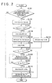
FIG. 2 is a flowchart showing the routine of the SOx poisoning recovery control executed in the exemplary embodiment. - In the following description and the accompanying drawings, the present invention will be described in more detail with reference to exemplary embodiments.
- To begin with, the outline of the structures of an internal combustion engine according to an exemplary embodiment of the invention and its intake system will be described.
FIG 1 schematically shows the structures of aninternal combustion engine 1 of the exemplary embodiment and its intake system. Theinternal combustion engine 1 is a diesel engine for vehicles. Theinternal combustion engine 1 has fourcylinders 2. Fuel injection valves 3 are provided in therespective cylinders 2. The fuel injection valves 3 directly inject fuel into therespective cylinders 2. - An
intake manifold 5 and an exhaust manifold 7 are connected to theinternal combustion engine 1. One end of an intake passage 4 is connected to theintake manifold 5, and one end of anexhaust passage 6 is connected to the exhaust manifold 7. - A
compressor 8a of a turbocharger (supercharging device) 8 is provided in the intake passage 4. Aturbine 8b of theturbocharger 8 is provided in theexhaust passage 6. Athrottle vale 16 is provided upstream of thecompressor 8a in the intake passage 4. - A
fuel addition valve 17 is provided upstream of theturbine 8b in theexhaust passage 6. Thefuel addition valve 17 is used to add fuel into the exhaust gas. ANOx catalyst 9 is provided downstream of theturbine 8b in theexhaust passage 6. Further, an air-fuel ratio sensor 14 for detecting an exhaust gas air-fuel ratio of the exhaust gas is provided upstream of theNOx catalyst 9 in theexhaust passage 6. Atemperature sensor 15 for detecting the exhaust gas temperature is provided downstream of theNOx catalyst 9 in theexhaust passage 6. Note that the "exhaust gas air-fuel ratio" represents the ratio between the air contained in an exhaust gas and the fuel element contained in the same exhaust gas and acting as a reducing agent at theNOx catalyst 9. - Further, the intake system of the
internal combustion engine 1 of this exemplary embodiment is equipped with anEGR apparatus 11 that distributes an exhaust gas to the intake system as an EGR gas. TheEGR apparatus 11 has anEGR passage 12 that is connected at one end to the exhaust manifold 7 and at the other end to theintake manifold 5. The EGR gas is distributed from the exhaust manifold 7 to theintake manifold 5 via theEGR passage 12. Further, anEGR valve 13 for controlling the amount of the EGR gas distributed to theintake manifold 5 is provided in theEGR passage 12. - The
internal combustion engine 1 is provided with an electronic control unit (ECU) 10. The air-fuel ratio sensor 14 and thetemperature sensor 15 are electrically connected to theECU 10, and theECU 10 receives signals from these sensors. TheECU 10 estimates the temperature of theNOx catalyst 9 based on the values detected by thetemperature sensor 15. - The fuel injection valve 3, the
throttle valve 16, thefuel addition valve 17, and theEGR valve 13 are electrically connected to theECU 10, and theECU 10 controls these valves. - Next, the SOx poisoning recovery control executed in this exemplary embodiment will be described. In the
internal combustion engine 1, the SOx poisoning recovery control is executed to reduce the SOx adsorbed in theNOx catalyst 9. During the SOx poisoning recovery control, it is necessary to reduce the exhaust gas air-fuel ratio of the exhaust gas entering the NOx catalyst 9 (will hereinafter be referred to as "catalyst-entering exhaust gas") to a target exhaust gas air-fuel ratio enabling SOx reduction reactions and reduce the temperature of theNOx catalyst 9 to a target temperature enabling SOx reduction reactions. - The exhaust gas air-fuel ratio of the exhaust gas discharged from the internal combustion engine 1 (will hereinafter be referred to as "engine-out exhaust gas") can be reduced by reducing the air-fuel ratio of the gas combusted in each
cylinder 2 of theinternal combustion engine 1. Thus, the exhaust gas air-fuel ratio of the catalyst-entering exhaust gas can be reduced by reducing the air-fuel ratio of the gas combusted in eachcylinder 2. - For example, the exhaust gas air-fuel ratio of the engine-out exhaust gas can be reduced by: (1) reducing the intake air amount by reducing the opening degree of the
throttle valve 16; (2) increasing the amount of EGR gas by increasing the opening degree of theEGR valve 13; (3) retarding the fuel injection timing of each fuel injection valve 3 and increasing the fuel injection amount; and (4) reducing the main injection amount and performing a post-injection at a time that is later than the main fuel injection and at which the injected main fuel is combusting. In this exemplary embodiment, the exhaust gas air-fuel ratio of the engine-out exhaust gas is reduced by implementing one of these methods (1) to (4) or by implementing two or more of them in combination. - Assuming that the fuel injected from each fuel injection valve 3 can be sufficiently combusted in the
cylinder 2 to generate torque during the implementation of a selected one or more of the foregoing methods (1) to (4), the fuel economy can be maintained even when the exhaust gas air-fuel ratio of the engine-out exhaust gas is being reduced using the foregoing methods (1) to (4). - However, in fact, if the exhaust gas air-fuel ratio of the engine-out exhaust gas is excessively reduced during the implementation of a selected one or more of the above-described methods (1) to (4), the fuel injected from the fuel injection valves 3 can not be sufficiently combusted in the
cylinders 2, and this increases the amount of smoke discharged from theinternal combustion engine 1, Because this smoke does not act as a reducing agent at theNOx catalyst 9, as the percentage of fuel that turns into such smoke after injected from the fuel injection valves 3 increases, the amount of fuel injected from the fuel injection valves 3 needs to be increased in order to reduce the exhaust gas air-fuel ratio of the engine-out exhaust gas (i.e., in order to increase the amount of fuel that acts as a reducing agent at the NOx catalyst 9). In this exemplary embodiment, the foregoing smoke corresponds to "non-reductive fuel element". - Meanwhile, another option for reducing the exhaust gas air-fuel ratio of the catalyst-entering exhaust gas is to add fuel into the exhaust gas from the
fuel addition valve 17. The fuel injected from thefuel addition valve 17 does not turn into smoke although it does not contribute to the generation of torque. - Thus, for the purpose of reducing the exhaust gas air-fuel ratio of the catalyst-entering exhaust gas down to the target exhaust gas air-fuel ratio and increasing the temperature of the
NOx catalyst 9 up to the target temperature, in the SOx poisoning recovery control of this exemplary embodiment, the exhaust gas air-fuel ratio of the engine-out exhaust gas is reduced and the amount of fuel added from thefuel addition valve 17 is controlled so as to minimize the sum of the amount of fuel injected from the fuel injection valves 3 and the amount of fuel injected from thefuel addition valve 17. - Hereinafter, the routine of the SOx poisoning recovery control executed in this exemplary embodiment will be described with reference to the flowchart shown in
FIG. 2 . This control routine is prestored in theECU 10 and is repeatedly executed at predetermined time intervals during the operation of theinternal combustion engine 1. - In this control routine, the
ECU 10 first determines whether the condition for executing the SOx poisoning recovery control is presently in effect in step 101. This condition is, for example, that a predetermined time has passed since the SOx poisoning recovery control was executed the last time. If a positive determination is made in step 101, theECU 10 then proceeds to step 102. If a negative determination is made, theECU 10 finishes the present cycle of the control routine. - In step 102, the
ECU 10 calculates a lower limit value Relimit of an exhaust gas air-fuel ratio Re of the engine-out exhaust gas. The lower limit value Relimit is used when reducing the exhaust gas air-fuel ratio Re using a selected one or more of the methods (1) to (4). The lower limit value Relimit corresponds to an exhaust gas air-fuel ratio at which the amount of smoke discharged from theinternal combustion engine 1 reaches its upper limit value. This upper limit value is a threshold used to determine whether the fuel used for further reducing an exhaust gas air-fuel ratio Rin of the catalyst-entering exhaust gas can be saved by accomplishing the reduction by adding fuel into the exhaust gas from thefuel addition valve 17 or by accomplishing the reduction by reducing the exhaust air-fuel ratio Re of the engine-out exhaust gas by reducing the air-fuel ratio of the gas to be combusted in theinternal combustion engine 1. That is, if the amount of smoke is larger than the upper limit value, the fuel amount needed to bring about a given reduction of the exhaust gas air-fuel ratio Rin of the catalyst-entering exhaust gas is considered to be smaller when the same reduction of the exhaust gas air-fuel ratio Rin is accomplished by adding fuel into the exhaust gas from thefuel addition valve 17 than when the same reduction of the exhaust gas air-fuel ratio Rin is accomplished by reducing the exhaust gas air-fuel ratio Re of the engine-out exhaust gas by reducing the air-fuel ratio of the gas to be combusted in theinternal combustion engine 1. - The method for reducing the exhaust gas air-fuel ratio Re of the engine-out exhaust gas is selected from among the foregoing methods (1) to (4) in accordance with the operation state of the
internal combustion engine 1. The lower limit value Relimit of the exhaust gas air-fuel ratio Re is set in accordance with the operation state of theinternal combustion engine 1. - After step 102, the
ECU 10 proceeds to step 103 and determines whether the lower limit value Relimit is larger than a target exhaust gas air-fuel ratio Rt. If a positive determination is made in step 103, theECU 10 proceeds to step 104. If a negative determination is made in step 103, it means that the exhaust gas air-fuel ratio Rin of the catalyst-entering exhaust gas can be reduced down to the target exhaust gas air-fuel ratio Rt only by reducing the exhaust gas air-fuel ratio Re of the engine-out exhaust gas to the target exhaust gas air-fuel ratio Rt. In this case, therefore, theECU 10 proceeds to step 112. - On the other hand, in step 104, the
ECU 10 calculates a fuel shortfall Qfd that is the amount of fuel that will be additionally required to further reduce the exhaust gas air-fuel ratio Rin of the catalyst-entering exhaust gas to the target exhaust gas air-fuel ratio Rt after reducing the exhaust gas air-fuel ratio Re of the engine-out exhaust gas to the lower limit value Relimit. - Then, the
ECU 10 proceeds to step 105 and reduces the exhaust gas air-fuel ratio Re of the engine-out exhaust gas down to the lower limit value Relimit using a selected one or more of the foregoing methods (1) to (4). - Then, the
ECU 10 proceeds to step 106 and controls thefuel addition valve 17 to add, into the exhaust gas, fuel of an amount corresponding to the fuel shortfall Qfd, whereby the exhaust gas air-fuel ratio Rin of the catalyst-entering exhaust gas equals the target exhaust gas air-fuel ratio Rt. - Next, the
ECU 10 proceeds to step 107 and determines whether a temperature Tc of theNOx catalyst 9 is presently lower than a target temperature Tt. If a positive determination is made in step 107, theECU 10 proceeds to step 108. If a negative determination is made in step 108, it means that the exhaust gas air-fuel ratio Rin of the catalyst-entering exhaust gas is presently equal to the target exhaust gas air-fuel ratio Rt and the temperature Tc of theNOx catalyst 9 is equal to or higher than the target temperature Tt, that is, reduction reactions of the SOx adsorbed in theNOx catalyst 9 can occur. In this case, therefore, theECU 10 finishes the present cycle of the control routine. - On the other hand, in step 108, the
ECU 10 increases the amount of fuel added from thefuel addition valve 17. Thus, the amount of fuel oxidized at theNOx catalyst 9 increases, and therefore the oxidization heat generated by the oxidization of fuel increases, whereby the temperature of the NOx catalyst increases. - Next, the
ECU 10 proceeds to step 109 and determines whether the temperature Tc of theNOx catalyst 9 has become equal to or higher than the target temperature Tt. If a positive determination is made in step 109, theECU 10 proceeds to step 110. If a negative determination is made in step 109, theECU 10 returns to step 108 and further increases the amount of fuel added from thefuel addition valve 17. - In step 110, the
ECU 10 calculates a decrease amount ΔRin that is the amount by which the exhaust gas air-fuel ratio Rin of the catalyst-entering exhaust gas has decreased due to the increase in the amount of fuel added from thefuel addition valve 17. - Then, the
ECU 10 proceeds to step 111 and performs a control that increases the exhaust gas air-fuel ratio Re of the engine-out exhaust gas by an amount corresponding to the calculated decrease amount ΔRin. In this way, the temperature Tc of theNOx catalyst 9 is made equal to or higher than the target temperature Tt and the exhaust gas air-fuel ratio Rin of the catalyst-entering exhaust gas is made equal to the target exhaust gas air-fuel ratio Rt, that is, a state where reduction reactions of the SOx adsorbed in theNOx catalyst 9 occur is developed. After step 111, theECU 10 finishes the present cycle of the control routine. - On the other hand, in step 112, the
ECU 10 reduces the exhaust gas air-fuel ratio Re of the engine-out exhaust gas down to the target exhaust gas air-fuel ratio Rt using a selected one or more of the foregoing methods (1) to (4). Then, theECU 10 proceeds to step 107 and to step 108. In step 108, theECU 10 controls thefuel addition valve 17 to add fuel into exhaust gas, after which theECU 10 proceeds to step 109. - As such, the control routine described above minimizes the sum of the amount of fuel injected from the fuel injection valves 3 and the amount of fuel added from the
fuel addition valve 17 when reducing the exhaust gas air-fuel ratio Rin of the catalyst-entering exhaust gas to the target exhaust gas air-fuel ratio Rt and increasing the temperature Tc of theNOx catalyst 9 to the target temperature Tt. - According to this exemplary embodiment, therefore, it is possible to minimize the reduction of the fuel economy that may be caused by the SOx poisoning recovery control.
- In the exemplary embodiment described above, the smoke discharged from the engine is recited as an example of "non-reductive fuel element". However, if the fuel injected from the fuel injection valve 3 is not sufficiently combusted in the
cylinder 2, the uncombusted fuel may turn into soot. The soot, like the smoke described above, does not act as a reducing agent at theNOx catalyst 9. Therefore, in the SOx poisoning recovery control described above, the lower limit value Relimit of the exhaust gas air-fuel ratio Re of the engine-out exhaust gas may be set to a value at which the amount of soot reaches its upper limit value. Like the above-described upper limit value of the smoke amount, the upper limit value of the soot amount is a threshold used to determine whether the fuel used for further reducing the exhaust gas air-fuel ratio Rin of the catalyst-entering exhaust gas can be saved by accomplishing the reduction by adding fuel into the exhaust gas from thefuel addition valve 17 or by accomplishing the reduction by reducing the exhaust air-fuel ratio Re by reducing the air-fuel ratio of the gas to be combusted in theinternal combustion engine 1. That is, if the amount of soot is larger than the upper limit value, the fuel amount needed to bring about a given reduction of the exhaust gas air-fuel ratio Rin of the catalyst-entering exhaust gas is considered to be smaller when the same reduction of the exhaust gas air-fuel ratio Rin is accomplished by adding fuel into the exhaust gas from thefuel addition valve 17 than when the same reduction of the exhaust gas air-fuel ratio Rin is accomplished by reducing the exhaust gas air-fuel ratio Re of the engine-out exhaust gas by reducing the air-fuel ratio of the gas to be combusted in theinternal combustion engine 1.
Claims (2)
- Use of an exhaust gas purification system for an internal combustion engine (1) for carrying out an exhaust gas purification method enabling SOx reduction reactions, comprising:an adsorption-reduction type NOx catalyst (9) that is provided in an exhaust passage (6) of the internal combustion engine (1) and adsorbs NOx and reduces the adsorbed NOx using a reducing agent;an engine air-fuel ratio control device (3, 10) that controls an engine-out exhaust gas air-fuel ratio (Re), which is the ratio between an air contained in an exhaust gas discharged from the internal combustion engine (1) and a fuel element contained in the same exhaust gas and acting as a reducing agent at the adsorption-reduction type NOx catalyst (9), by controlling the air-fuel ratio of a gas to be combusted in the internal combustion engine (1);a fuel addition device (17) that is provided upstream of the adsorption-reduction type NOx catalyst (9) in the exhaust passage (6) and adds fuel into an exhaust gas;a SOx poisoning recovery control device (10) that executes a SOx poisoning recovery control for reducing SOx adsorbed in the adsorption-reduction type NOx catalyst (9), in which the engine-out exhaust gas air-fuel ratio (Re) is controlled by the engine air-fuel ratio control device (3, 10) and fuel is added into the exhaust gas from the fuel addition device (17) such that a catalyst-entering exhaust gas air-fuel ratio (Rin), which is the ratio between an air contained in an exhaust gas entering the adsorption-reduction type NOx catalyst (9) and a fuel element contained in the same exhaust gas and acting as a reducing agent at the adsorption-reduction type NOx catalyst (9), decreases to a target exhaust gas air-fuel ratio (Rt) enabling SOx reduction reactions and such that the temperature (Tc) of the adsorption-reduction type NOx catalyst (9) increases to a target temperature (Tt) enabling SOx reduction reactions, the exhaust gas purification system being characterized in that:when reducing the catalyst-entering exhaust gas air-fuel ratio (Rin) to the target exhaust gas air-fuel ratio (Rt) and increasing the temperature (Tc) of the adsorption-reduction type NOx catalyst (9) to the target temperature (Tt), the SOx poisoning recovery control device (10) controls the engine-out exhaust gas air-fuel ratio (Re) using the engine air-fuel ratio control device (3, 10) and controls the amount of fuel added from the fuel addition device (17) so as to minimize the sum of the amount of fuel injected in the internal combustion engine (1) and the amount of fuel added from the fuel addition device (17);if the temperature (Tc) of the adsorption-reduction type NOx catalyst (9) is still lower than the target temperature (Tt) after the catalyst-entering exhaust gas air-fuel ratio (Rin) has been reduced to the target exhaust gas air-fuel ratio (Rt), the SOx poisoning recovery control device (10) increases the amount of fuel added from the fuel addition device (17) such that the temperature (Tc) of the adsorption-reduction type NOx catalyst (9) increases to the target temperature (Tt);when reducing the catalyst-entering exhaust gas air-fuel ratio (Rin) to the target exhaust gas air-fuel ratio (Rt), the SOx poisoning recovery control device (10) reduces the engine-out exhaust gas air-fuel ratio (Re) to a level at which the amount of a fuel element contained in the exhaust gas discharged from the internal combustion engine (1) and not acting as a reducing agent at the adsorption-reduction type NOx catalyst (9) reaches an upper limit value (Relimit), wherein the non-reductive fuel element is smoke or soot, and the SOx poisoning recovery control device (10) controls the fuel addition device (17) to add, into the exhaust gas, fuel of an amount needed to compensate for the shortfall in the fuel amount required to reduce the catalyst-entering exhaust gas air-fuel ratio (Rin) to the target exhaust gas air-fuel ratio (Rt);wherein the upper limit value (Relimit) of the non-reductive fuel element is a threshold used to determine whether the fuel used for further reducing the catalyst-entering exhaust gas air-fuel ratio (Rin) can be saved by accomplishing the reduction by adding fuel into the exhaust gas from the fuel addition device (17) or by accomplishing the reduction by reducing the engine-out exhaust gas air-fuel ratio (Re) by reducing the air-fuel ratio of the gas to be combusted in the internal combustion engine (1);andwherein, if the amount of the non-reductive fuel element is larger than the upper limit value (Relimit), the fuel amount needed to bring about a given reduction of the catalyst-entering exhaust gas air-fuel ratio (Rin) is considered to be smaller when the same reduction of the catalyst-entering exhaust gas air-fuel ratio (Rin) is accomplished by adding fuel into the exhaust gas from the fuel addition device (17) than when the same reduction of the catalyst-entering exhaust gas air-fuel ratio (Rin) is accomplished by reducing the engine-out exhaust gas air-fuel ratio (Re) by reducing the air-fuel ratio of the gas to be combusted in the internal combustion engine (1);when controlling the catalyst-entering exhaust gas air-fuel ratio (Rin) to the target exhaust gas air-fuel ratio (Rt), the SOx poisoning recovery control device (10) increases using the engine air-fuel ratio control device (10), the engine-out exhaust gas air-fuel ratio (Re) by an amount corresponding to the amount by which the catalyst-entering exhaust gas air-fuel ratio (Rin) has decreased due to the increase in the amount of fuel added from the fuel addition device (17).
- An exhaust gas purification method for an internal combustion engine (1) including: an adsorption-reduction type NOx catalyst (9) that is provided in an exhaust passage (6) of the internal combustion engine (1) and adsorbs NOx and reduces the adsorbed NOx using a reducing agent; and a fuel addition device (17) that is provided upstream of the adsorption-reduction type NOx catalyst (9) in the exhaust passage (6) and adds fuel into an exhaust gas, the exhaust gas purification method being characterized in that:when reducing a catalyst-entering exhaust gas air-fuel ratio (Rin), which is the ratio between an air contained in an exhaust gas entering the adsorption-reduction type NOx catalyst (9) and a fuel element contained in the same exhaust gas and acting as a reducing agent at the adsorption-reduction type NOx catalyst (9), to a target exhaust gas air-fuel ratio (Rt) enabling SOx reduction reactions and increasing the temperature (Tc) of the adsorption-reduction type NOx catalyst (9) to a target temperature (Tt) enabling SOx reduction reactions, an engine-out exhaust gas air-fuel ratio (Re), which is the ratio between an air contained in an exhaust gas discharged from the internal combustion engine (1) and a fuel element contained in the same exhaust gas and acting as a reducing agent at the adsorption-reduction type NOx catalyst (9), and the amount of fuel added from the fuel addition device (17) are controlled so as to minimize the sum of the amount of fuel injected in the internal combustion engine (1) and the amount of fuel added from the fuel addition device (17); if the temperature (Tc) of the adsorption-reduction type NOx catalyst (9) is still lower than the target temperature (Tt) after the catalyst-entering exhaust gas air-fuel ratio (Rin) has been reduced to the target exhaust gas air-fuel ratio (Rt), the amount of fuel added from the fuel addition device (17) is increased such that the temperature (Tc) of the adsorption-reduction type NOx catalyst (9) increases to the target temperature (Tt);when reducing the catalyst-entering exhaust gas air-fuel ratio (Rin) to the target exhaust gas air-fuel ratio (Rt), the engine-out exhaust gas air-fuel ratio (Re) is reduced to a level at which the amount of a fuel element contained in the exhaust gas discharged from the internal combustion engine (1) and not acting as a reducing agent at the adsorption-reduction type NOx catalyst (9) reaches an upper limit value (Relimit), wherein the non-reductive fuel element is smoke or soot, and fuel of an amount needed to compensate for the shortfall in the fuel amount required to reduce the catalyst-entering exhaust gas air-fuel ratio (Rin) to the target exhaust gas air-fuel ratio (Rt) is added into the exhaust gas from the fuel addition device (17);wherein the upper limit value (Relimit) of the non-reductive fuel element is a threshold used to determine whether the fuel used for further reducing the catalyst-entering exhaust gas air-fuel ratio (Rin) can be saved by accomplishing the reduction by adding fuel into the exhaust gas from the fuel addition device (17) or by accomplishing the reduction by reducing the engine-out exhaust gas air-fuel ratio (Re) by reducing the air-fuel ratio of the gas to be combusted in the internal combustion engine (1); andwherein, if the amount of the non-reductive fuel element is larger than the upper limit value (Relimit), the fuel amount needed to bring about a given reduction of the catalyst-entering exhaust gas air-fuel ratio (Rin) is considered to be smaller when the same reduction of the catalyst-entering exhaust gas air-fuel ratio (Rin) is accomplished by adding fuel into the exhaust gas from the fuel addition device (17) than when the same reduction of the catalyst-entering exhaust gas air-fuel ratio (Rin) is accomplished by reducing the engine-out exhaust gas air-fuel ratio (Re) by reducing the air-fuel ratio of the gas to be combusted in the internal combustion engine (1);when controlling the catalyst-entering exhaust gas air-fuel ratio (Rin) to the target exhaust gas air-fuel ratio (Rt), the engine-out exhaust gas air-fuel ratio (Re) is increased by an amount corresponding to the amount by which the catalyst-entering exhaust gas air-fuel ratio (Rin) has decreased due to the increase in the amount of fuel added from the fuel addition device (17).
Applications Claiming Priority (2)
| Application Number | Priority Date | Filing Date | Title |
|---|---|---|---|
| JP2006233279A JP4241784B2 (en) | 2006-08-30 | 2006-08-30 | Exhaust gas purification system for internal combustion engine |
| PCT/IB2007/002476 WO2008029239A1 (en) | 2006-08-30 | 2007-08-29 | Exhaust gas purification system and method for internal combustion engine |
Publications (2)
| Publication Number | Publication Date |
|---|---|
| EP2059664A1 EP2059664A1 (en) | 2009-05-20 |
| EP2059664B1 true EP2059664B1 (en) | 2013-05-01 |
Family
ID=38920721
Family Applications (1)
| Application Number | Title | Priority Date | Filing Date |
|---|---|---|---|
| EP07804847.7A Not-in-force EP2059664B1 (en) | 2006-08-30 | 2007-08-29 | Exhaust gas purification system and method for internal combustion engine |
Country Status (5)
| Country | Link |
|---|---|
| US (1) | US8061125B2 (en) |
| EP (1) | EP2059664B1 (en) |
| JP (1) | JP4241784B2 (en) |
| CN (1) | CN101506501B (en) |
| WO (1) | WO2008029239A1 (en) |
Families Citing this family (4)
| Publication number | Priority date | Publication date | Assignee | Title |
|---|---|---|---|---|
| US9062569B2 (en) * | 2010-10-29 | 2015-06-23 | General Electric Company | Systems, methods, and apparatus for regenerating a catalytic material |
| US9359918B2 (en) * | 2010-10-29 | 2016-06-07 | General Electric Company | Apparatus for reducing emissions and method of assembly |
| US20120102951A1 (en) * | 2010-10-29 | 2012-05-03 | Gilbert Otto Kraemer | Apparatus for reducing emissions and method of assembly |
| CN103210197B (en) * | 2010-11-02 | 2016-03-09 | 丰田自动车株式会社 | The control gear of internal-combustion engine |
Citations (1)
| Publication number | Priority date | Publication date | Assignee | Title |
|---|---|---|---|---|
| JP2005273573A (en) * | 2004-03-25 | 2005-10-06 | Toyota Motor Corp | Exhaust emission control device for internal combustion engine |
Family Cites Families (15)
| Publication number | Priority date | Publication date | Assignee | Title |
|---|---|---|---|---|
| US6519933B2 (en) * | 2000-03-21 | 2003-02-18 | Toyota Jidosha Kabushiki Kaisha | Internal combustion engine having variable valve control system and NOx catalyst |
| JP3508691B2 (en) | 2000-03-31 | 2004-03-22 | トヨタ自動車株式会社 | Exhaust gas purification device for internal combustion engine |
| JP2002155724A (en) | 2000-09-07 | 2002-05-31 | Toyota Motor Corp | Exhaust emission control device |
| JP3645841B2 (en) * | 2001-08-28 | 2005-05-11 | 本田技研工業株式会社 | Exhaust gas purification device for internal combustion engine |
| JP3835241B2 (en) | 2001-10-15 | 2006-10-18 | トヨタ自動車株式会社 | Exhaust gas purification device for internal combustion engine |
| JP4239765B2 (en) | 2003-09-10 | 2009-03-18 | トヨタ自動車株式会社 | Exhaust purification catalyst control method and exhaust purification catalyst control apparatus for internal combustion engine |
| JP4020054B2 (en) * | 2003-09-24 | 2007-12-12 | トヨタ自動車株式会社 | Exhaust gas purification system for internal combustion engine |
| JP3876874B2 (en) | 2003-10-28 | 2007-02-07 | トヨタ自動車株式会社 | Catalyst regeneration method |
| JP4415648B2 (en) | 2003-11-05 | 2010-02-17 | いすゞ自動車株式会社 | Sulfur purge control method and exhaust gas purification system |
| JP4311169B2 (en) | 2003-11-14 | 2009-08-12 | トヨタ自動車株式会社 | Exhaust gas purification device for internal combustion engine |
| JP2005240682A (en) | 2004-02-26 | 2005-09-08 | Toyota Motor Corp | Exhaust emission control device for internal combustion engine |
| JP2005291100A (en) * | 2004-03-31 | 2005-10-20 | Mitsubishi Fuso Truck & Bus Corp | Exhaust emission control device for engine |
| US20050223698A1 (en) | 2004-03-31 | 2005-10-13 | Mitsubishi Fuso Truck And Bus Corporation | Exhaust gas cleaning device |
| JP4548143B2 (en) | 2005-02-16 | 2010-09-22 | トヨタ自動車株式会社 | Exhaust gas purification device for hybrid vehicle |
| JP4417878B2 (en) * | 2005-05-16 | 2010-02-17 | いすゞ自動車株式会社 | Exhaust gas purification method and exhaust gas purification system |
-
2006
- 2006-08-30 JP JP2006233279A patent/JP4241784B2/en not_active Expired - Fee Related
-
2007
- 2007-08-29 CN CN2007800309738A patent/CN101506501B/en not_active Expired - Fee Related
- 2007-08-29 WO PCT/IB2007/002476 patent/WO2008029239A1/en active Application Filing
- 2007-08-29 US US12/310,066 patent/US8061125B2/en not_active Expired - Fee Related
- 2007-08-29 EP EP07804847.7A patent/EP2059664B1/en not_active Not-in-force
Patent Citations (1)
| Publication number | Priority date | Publication date | Assignee | Title |
|---|---|---|---|---|
| JP2005273573A (en) * | 2004-03-25 | 2005-10-06 | Toyota Motor Corp | Exhaust emission control device for internal combustion engine |
Also Published As
| Publication number | Publication date |
|---|---|
| US20090199548A1 (en) | 2009-08-13 |
| EP2059664A1 (en) | 2009-05-20 |
| CN101506501A (en) | 2009-08-12 |
| WO2008029239A1 (en) | 2008-03-13 |
| CN101506501B (en) | 2012-05-23 |
| JP4241784B2 (en) | 2009-03-18 |
| US8061125B2 (en) | 2011-11-22 |
| JP2008057369A (en) | 2008-03-13 |
Similar Documents
| Publication | Publication Date | Title |
|---|---|---|
| US8511068B2 (en) | Temperature raising system for an exhaust gas purification catalyst | |
| US8307638B2 (en) | Exhaust gas purification system for internal combustion engine | |
| US20090158713A1 (en) | Exhaust Gas Purification System for Internal Combustion Engine | |
| JP4645585B2 (en) | Engine torque control device | |
| JP4561656B2 (en) | Catalyst temperature estimation device for internal combustion engine | |
| JP5045339B2 (en) | Exhaust gas purification system for internal combustion engine | |
| US7827783B2 (en) | Exhaust gas purifying apparatus for internal combustion engine | |
| EP2059664B1 (en) | Exhaust gas purification system and method for internal combustion engine | |
| JP2007239493A (en) | Internal combustion engine with supercharger | |
| US8020375B2 (en) | Exhaust gas purification system for internal combustion engine | |
| EP2211037B1 (en) | Exhaust gas purification system for internal combustion engine | |
| JP2002188430A (en) | Exhaust gas purifying device of internal combustion engine | |
| JP2008231926A (en) | Exhaust emission control device of internal combustion engine | |
| JPH11117726A (en) | Catalyst degradation diagnostic device for internal combustion engine | |
| CN110945218B (en) | Exhaust gas purification system | |
| EP1517030B1 (en) | Method and apparatus for detecting deterioration in fuel injection amount of internal combustion engine | |
| JP3799770B2 (en) | Catalyst deterioration diagnosis device for internal combustion engine | |
| JP5083398B2 (en) | Engine torque control device | |
| JP2021050650A (en) | Exhaust emission control device for engine | |
| JP2008038825A (en) | Internal combustion engine control device | |
| US8096113B2 (en) | Exhaust purification system for internal combustion engine | |
| JP2009156153A (en) | Fuel injection control system for internal combustion engine | |
| US20110231079A1 (en) | Method and device for operating an internal combustion engine | |
| JPH11311118A (en) | Exhaust emission control device of turbocharged engine and control method thereof | |
| JP2007278246A (en) | Exhaust emission control device for internal combustion engine |
Legal Events
| Date | Code | Title | Description |
|---|---|---|---|
| PUAI | Public reference made under article 153(3) epc to a published international application that has entered the european phase |
Free format text: ORIGINAL CODE: 0009012 |
|
| 17P | Request for examination filed |
Effective date: 20090330 |
|
| AK | Designated contracting states |
Kind code of ref document: A1 Designated state(s): AT BE BG CH CY CZ DE DK EE ES FI FR GB GR HU IE IS IT LI LT LU LV MC MT NL PL PT RO SE SI SK TR |
|
| AX | Request for extension of the european patent |
Extension state: AL BA HR MK RS |
|
| RBV | Designated contracting states (corrected) |
Designated state(s): DE FR GB |
|
| 17Q | First examination report despatched |
Effective date: 20110415 |
|
| DAX | Request for extension of the european patent (deleted) | ||
| GRAP | Despatch of communication of intention to grant a patent |
Free format text: ORIGINAL CODE: EPIDOSNIGR1 |
|
| RIC1 | Information provided on ipc code assigned before grant |
Ipc: F01N 3/20 20060101ALI20121022BHEP Ipc: F02D 41/14 20060101ALI20121022BHEP Ipc: F02D 41/02 20060101AFI20121022BHEP Ipc: F01N 3/08 20060101ALI20121022BHEP |
|
| RAP1 | Party data changed (applicant data changed or rights of an application transferred) |
Owner name: TOYOTA JIDOSHA KABUSHIKI KAISHA |
|
| GRAS | Grant fee paid |
Free format text: ORIGINAL CODE: EPIDOSNIGR3 |
|
| GRAA | (expected) grant |
Free format text: ORIGINAL CODE: 0009210 |
|
| RIN1 | Information on inventor provided before grant (corrected) |
Inventor name: NISHIOKA, HIROMASA Inventor name: ASANUMA, TAKAMITSU Inventor name: YOSHIDA, KOHEI |
|
| AK | Designated contracting states |
Kind code of ref document: B1 Designated state(s): DE FR GB |
|
| REG | Reference to a national code |
Ref country code: GB Ref legal event code: FG4D |
|
| REG | Reference to a national code |
Ref country code: DE Ref legal event code: R096 Ref document number: 602007030200 Country of ref document: DE Effective date: 20130627 |
|
| PLBE | No opposition filed within time limit |
Free format text: ORIGINAL CODE: 0009261 |
|
| STAA | Information on the status of an ep patent application or granted ep patent |
Free format text: STATUS: NO OPPOSITION FILED WITHIN TIME LIMIT |
|
| 26N | No opposition filed |
Effective date: 20140204 |
|
| GBPC | Gb: european patent ceased through non-payment of renewal fee |
Effective date: 20130829 |
|
| REG | Reference to a national code |
Ref country code: DE Ref legal event code: R097 Ref document number: 602007030200 Country of ref document: DE Effective date: 20140204 |
|
| REG | Reference to a national code |
Ref country code: FR Ref legal event code: ST Effective date: 20140430 |
|
| PG25 | Lapsed in a contracting state [announced via postgrant information from national office to epo] |
Ref country code: GB Free format text: LAPSE BECAUSE OF NON-PAYMENT OF DUE FEES Effective date: 20130829 |
|
| PG25 | Lapsed in a contracting state [announced via postgrant information from national office to epo] |
Ref country code: FR Free format text: LAPSE BECAUSE OF NON-PAYMENT OF DUE FEES Effective date: 20130902 |
|
| REG | Reference to a national code |
Ref country code: DE Ref legal event code: R084 Ref document number: 602007030200 Country of ref document: DE |
|
| PGFP | Annual fee paid to national office [announced via postgrant information from national office to epo] |
Ref country code: DE Payment date: 20180814 Year of fee payment: 12 |
|
| REG | Reference to a national code |
Ref country code: DE Ref legal event code: R119 Ref document number: 602007030200 Country of ref document: DE |
|
| PG25 | Lapsed in a contracting state [announced via postgrant information from national office to epo] |
Ref country code: DE Free format text: LAPSE BECAUSE OF NON-PAYMENT OF DUE FEES Effective date: 20200303 |