EP2059464B1 - Device for discharging elongate, coarse bulk products - Google Patents
Device for discharging elongate, coarse bulk products Download PDFInfo
- Publication number
- EP2059464B1 EP2059464B1 EP07801665A EP07801665A EP2059464B1 EP 2059464 B1 EP2059464 B1 EP 2059464B1 EP 07801665 A EP07801665 A EP 07801665A EP 07801665 A EP07801665 A EP 07801665A EP 2059464 B1 EP2059464 B1 EP 2059464B1
- Authority
- EP
- European Patent Office
- Prior art keywords
- discharge opening
- disc
- preforms
- screen
- diameter
- Prior art date
- Legal status (The legal status is an assumption and is not a legal conclusion. Google has not performed a legal analysis and makes no representation as to the accuracy of the status listed.)
- Not-in-force
Links
Images


Classifications
-
- B—PERFORMING OPERATIONS; TRANSPORTING
- B65—CONVEYING; PACKING; STORING; HANDLING THIN OR FILAMENTARY MATERIAL
- B65G—TRANSPORT OR STORAGE DEVICES, e.g. CONVEYORS FOR LOADING OR TIPPING, SHOP CONVEYOR SYSTEMS OR PNEUMATIC TUBE CONVEYORS
- B65G47/00—Article or material-handling devices associated with conveyors; Methods employing such devices
- B65G47/74—Feeding, transfer, or discharging devices of particular kinds or types
- B65G47/84—Star-shaped wheels or devices having endless travelling belts or chains, the wheels or devices being equipped with article-engaging elements
- B65G47/846—Star-shaped wheels or wheels equipped with article-engaging elements
- B65G47/848—Star-shaped wheels or wheels equipped with article-engaging elements the article-engaging elements being suction or magnetic means
-
- B—PERFORMING OPERATIONS; TRANSPORTING
- B29—WORKING OF PLASTICS; WORKING OF SUBSTANCES IN A PLASTIC STATE IN GENERAL
- B29C—SHAPING OR JOINING OF PLASTICS; SHAPING OF MATERIAL IN A PLASTIC STATE, NOT OTHERWISE PROVIDED FOR; AFTER-TREATMENT OF THE SHAPED PRODUCTS, e.g. REPAIRING
- B29C49/00—Blow-moulding, i.e. blowing a preform or parison to a desired shape within a mould; Apparatus therefor
- B29C49/42—Component parts, details or accessories; Auxiliary operations
- B29C49/4205—Handling means, e.g. transfer, loading or discharging means
-
- B—PERFORMING OPERATIONS; TRANSPORTING
- B65—CONVEYING; PACKING; STORING; HANDLING THIN OR FILAMENTARY MATERIAL
- B65G—TRANSPORT OR STORAGE DEVICES, e.g. CONVEYORS FOR LOADING OR TIPPING, SHOP CONVEYOR SYSTEMS OR PNEUMATIC TUBE CONVEYORS
- B65G15/00—Conveyors having endless load-conveying surfaces, i.e. belts and like continuous members, to which tractive effort is transmitted by means other than endless driving elements of similar configuration
- B65G15/30—Belts or like endless load-carriers
- B65G15/58—Belts or like endless load-carriers with means for holding or retaining the loads in fixed position, e.g. magnetic
-
- B—PERFORMING OPERATIONS; TRANSPORTING
- B65—CONVEYING; PACKING; STORING; HANDLING THIN OR FILAMENTARY MATERIAL
- B65G—TRANSPORT OR STORAGE DEVICES, e.g. CONVEYORS FOR LOADING OR TIPPING, SHOP CONVEYOR SYSTEMS OR PNEUMATIC TUBE CONVEYORS
- B65G29/00—Rotary conveyors, e.g. rotating discs, arms, star-wheels or cones
-
- B—PERFORMING OPERATIONS; TRANSPORTING
- B65—CONVEYING; PACKING; STORING; HANDLING THIN OR FILAMENTARY MATERIAL
- B65G—TRANSPORT OR STORAGE DEVICES, e.g. CONVEYORS FOR LOADING OR TIPPING, SHOP CONVEYOR SYSTEMS OR PNEUMATIC TUBE CONVEYORS
- B65G47/00—Article or material-handling devices associated with conveyors; Methods employing such devices
- B65G47/02—Devices for feeding articles or materials to conveyors
- B65G47/04—Devices for feeding articles or materials to conveyors for feeding articles
- B65G47/12—Devices for feeding articles or materials to conveyors for feeding articles from disorderly-arranged article piles or from loose assemblages of articles
- B65G47/14—Devices for feeding articles or materials to conveyors for feeding articles from disorderly-arranged article piles or from loose assemblages of articles arranging or orientating the articles by mechanical or pneumatic means during feeding
- B65G47/1407—Devices for feeding articles or materials to conveyors for feeding articles from disorderly-arranged article piles or from loose assemblages of articles arranging or orientating the articles by mechanical or pneumatic means during feeding the articles being fed from a container, e.g. a bowl
- B65G47/1442—Devices for feeding articles or materials to conveyors for feeding articles from disorderly-arranged article piles or from loose assemblages of articles arranging or orientating the articles by mechanical or pneumatic means during feeding the articles being fed from a container, e.g. a bowl by means of movement of the bottom or a part of the wall of the container
- B65G47/1457—Rotating movement in the plane of the rotating part
-
- B—PERFORMING OPERATIONS; TRANSPORTING
- B29—WORKING OF PLASTICS; WORKING OF SUBSTANCES IN A PLASTIC STATE IN GENERAL
- B29C—SHAPING OR JOINING OF PLASTICS; SHAPING OF MATERIAL IN A PLASTIC STATE, NOT OTHERWISE PROVIDED FOR; AFTER-TREATMENT OF THE SHAPED PRODUCTS, e.g. REPAIRING
- B29C49/00—Blow-moulding, i.e. blowing a preform or parison to a desired shape within a mould; Apparatus therefor
- B29C49/42—Component parts, details or accessories; Auxiliary operations
- B29C49/78—Measuring, controlling or regulating
- B29C2049/7874—Preform or article shape, weight, defect or presence
- B29C2049/7876—Defects
-
- B—PERFORMING OPERATIONS; TRANSPORTING
- B29—WORKING OF PLASTICS; WORKING OF SUBSTANCES IN A PLASTIC STATE IN GENERAL
- B29C—SHAPING OR JOINING OF PLASTICS; SHAPING OF MATERIAL IN A PLASTIC STATE, NOT OTHERWISE PROVIDED FOR; AFTER-TREATMENT OF THE SHAPED PRODUCTS, e.g. REPAIRING
- B29C2949/00—Indexing scheme relating to blow-moulding
- B29C2949/07—Preforms or parisons characterised by their configuration
- B29C2949/0715—Preforms or parisons characterised by their configuration the preform having one end closed
-
- B—PERFORMING OPERATIONS; TRANSPORTING
- B29—WORKING OF PLASTICS; WORKING OF SUBSTANCES IN A PLASTIC STATE IN GENERAL
- B29C—SHAPING OR JOINING OF PLASTICS; SHAPING OF MATERIAL IN A PLASTIC STATE, NOT OTHERWISE PROVIDED FOR; AFTER-TREATMENT OF THE SHAPED PRODUCTS, e.g. REPAIRING
- B29C49/00—Blow-moulding, i.e. blowing a preform or parison to a desired shape within a mould; Apparatus therefor
- B29C49/02—Combined blow-moulding and manufacture of the preform or the parison
- B29C49/06—Injection blow-moulding
-
- B—PERFORMING OPERATIONS; TRANSPORTING
- B29—WORKING OF PLASTICS; WORKING OF SUBSTANCES IN A PLASTIC STATE IN GENERAL
- B29C—SHAPING OR JOINING OF PLASTICS; SHAPING OF MATERIAL IN A PLASTIC STATE, NOT OTHERWISE PROVIDED FOR; AFTER-TREATMENT OF THE SHAPED PRODUCTS, e.g. REPAIRING
- B29C49/00—Blow-moulding, i.e. blowing a preform or parison to a desired shape within a mould; Apparatus therefor
- B29C49/42—Component parts, details or accessories; Auxiliary operations
- B29C49/4205—Handling means, e.g. transfer, loading or discharging means
- B29C49/42051—Means for stripping, aligning or de-stacking
- B29C49/42057—Aligning disorderly arranged preforms, e.g. delivered disorderly
-
- B—PERFORMING OPERATIONS; TRANSPORTING
- B29—WORKING OF PLASTICS; WORKING OF SUBSTANCES IN A PLASTIC STATE IN GENERAL
- B29C—SHAPING OR JOINING OF PLASTICS; SHAPING OF MATERIAL IN A PLASTIC STATE, NOT OTHERWISE PROVIDED FOR; AFTER-TREATMENT OF THE SHAPED PRODUCTS, e.g. REPAIRING
- B29C49/00—Blow-moulding, i.e. blowing a preform or parison to a desired shape within a mould; Apparatus therefor
- B29C49/42—Component parts, details or accessories; Auxiliary operations
- B29C49/4205—Handling means, e.g. transfer, loading or discharging means
- B29C49/42073—Grippers
- B29C49/42077—Grippers with U-shaped holder
-
- B—PERFORMING OPERATIONS; TRANSPORTING
- B29—WORKING OF PLASTICS; WORKING OF SUBSTANCES IN A PLASTIC STATE IN GENERAL
- B29C—SHAPING OR JOINING OF PLASTICS; SHAPING OF MATERIAL IN A PLASTIC STATE, NOT OTHERWISE PROVIDED FOR; AFTER-TREATMENT OF THE SHAPED PRODUCTS, e.g. REPAIRING
- B29C49/00—Blow-moulding, i.e. blowing a preform or parison to a desired shape within a mould; Apparatus therefor
- B29C49/42—Component parts, details or accessories; Auxiliary operations
- B29C49/4205—Handling means, e.g. transfer, loading or discharging means
- B29C49/42073—Grippers
- B29C49/42089—Grippers holding body portion
-
- B—PERFORMING OPERATIONS; TRANSPORTING
- B29—WORKING OF PLASTICS; WORKING OF SUBSTANCES IN A PLASTIC STATE IN GENERAL
- B29C—SHAPING OR JOINING OF PLASTICS; SHAPING OF MATERIAL IN A PLASTIC STATE, NOT OTHERWISE PROVIDED FOR; AFTER-TREATMENT OF THE SHAPED PRODUCTS, e.g. REPAIRING
- B29C49/00—Blow-moulding, i.e. blowing a preform or parison to a desired shape within a mould; Apparatus therefor
- B29C49/42—Component parts, details or accessories; Auxiliary operations
- B29C49/42414—Treatment of preforms, e.g. cleaning or spraying water for improved heat transfer
- B29C49/42416—Purging or cleaning the preforms
- B29C49/42418—Purging or cleaning the preforms for sterilizing
Definitions
- the invention relates to a device for discharging elongate, coarse-bulk products from a container, in particular of PET bottle blanks (preforms) from a bulk hopper with a discharge opening, wherein the discharge opening is associated with a rotating disk.
- the products to be discharged and in particular the preforms are usually elongate and thus have a bulky shape and unfavorable for the discharge. This often leads to problems when emptying the containers, since the preforms are wedged into one another such that they do not slip or form bridges. Or it comes to avalanches, because too many products emerge at once through the discharge opening.
- the controlled discharge and metering is a major problem in the transfer of stored preforms, especially when the cross-sectional area of the discharge opening is smaller than the large cross-section of the container.
- From the DE 1 953 974 U is a device for the oriented juxtaposition of the same, disorderly supplied objects, in particular ampoules, known.
- a rotating disc is mounted under a container outlet.
- the object of the present invention is to provide a device of the above-mentioned. Type which allows a single-acting, gentle in the amount quickly varying dosage and passing or blocking the product flow.
- a diaphragm is provided between the discharge opening and the disc, which changes an annular opening (16) (round or polygonal) between the discharge opening (3) and the disc (5) in their width (w).
- the rotating disc means an active element, with which the products and in particular the preforms are discharged from the container.
- the possibility of changing the rotational speed of the rotating disk also opens up the possibility of precisely controlling the quantity of preforms to be discharged. If the disc is shifted to higher speeds, the discharge rate also increases. If the disc is stopped, no preforms are discharged, the discharge is locked.
- the superstructures on the surface of the disk cause preforms to be combed out of the discharge opening.
- the assemblies eccentrically, whereby a guiding of the preforms is improved to the outside.
- These structures may be, for example, wall strips that are formed radially straight or curved.
- the vertical opening width of an annular opening, round or polygonal is variable between the discharge opening and the disc.
- different forms of products to be discharged can be taken into account.
- a distribution surface is preferably provided, through which the products and in particular the preforms can be singulated.
- a distribution surface is preferably provided, through which the products and in particular the preforms can be singulated.
- Such a device is for example in the PCT / EP2006 / 050682 to which particular reference is made.
- the rotating disk produces a gently rotating dynamic column of preforms which propagate inside the container and ensure that the preforms slide off.
- a stirring finger for example a twisted stirring rod, is connected to the rotating disk and engages through the discharge opening into the container.
- This stirring rod has a pitch and is set in such a direction of rotation that an upward movement of the bulk material is effected, which avoids a bridge construction of the bulk material or dissolves existing bridges and secures the slipping.
- the utilization of the bulk container is ideal because the entire container volume can be used for storage.
- no volume-reducing baffles need to be installed to prevent bridge construction.
- the discharge is controlled, an avalanche-like discharge is not possible.
- the discharge of the bulk material is independent of the pressure on the rotating disc, whereby a uniform discharge over the entire filling spectrum and the filling level of the container is guaranteed.
- the products to be discharged can not jam between discharge belts and stationary parts, which otherwise led to disruptions.
- the dosage can be adapted very quickly and dynamically changing wishes to the bulk material supply.
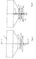
- FIG. 1 are located disorderly in a hopper 1, a plurality of preforms 2, which are to be discharged through a discharge opening 3.
- a nozzle 4 of the bulk material funnel 1 surrounds this discharge opening 3.
- a disc 5 is arranged below the discharge opening 3, which rests on a rotary shaft 6.
- the rotary shaft 6 rotates in two bearings 7.1 and 7.2 and is connected to a drive 8.
- the rotary shaft 6 is free of play by a distribution surface 9, which is also formed, for example, disc-shaped embrace.
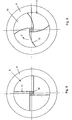
- FIGS. 6 to 9 On a surface 10 of the disc 5 constructions are placed, in particular in the FIGS. 6 to 9 are shown in more detail. According to the FIGS. 6 and 8th If the structures are straight wall strips 11, which are arranged eccentrically to a center M of the disc 5. In contrast, the surface 10 of the disc 5 according to the FIGS. 7 and 9 bent wall strip 12 is placed, wherein the curvature of the wall strip 12 of a rotational direction z of the disc 5 trails.
- FIG. 1 In FIG. 1 is indicated that the disc 5 rotatably seated on the rotary shaft 6.
- an extension 13 To the rotary shaft 6, an extension 13 connects, in which a twisted stirring rod 14 is inserted at the front.
- This twisted stirring rod 14 forms between its two ends of a widening and tapering belly.
- a diaphragm 15 may be placed, which is displaceable along the nozzle 4.
- the aperture 15 in this case has a slightly larger diameter d, as the diameter d 1 of the nozzle 4 (see FIG. 2 ).
- the discharge opening 3 has a diameter d 2 , which is not very different from a diameter d 3 of the disc 5 (see FIG. 3 ).
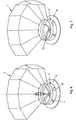
- the distribution surface does not necessarily have to be flat, but also as a cone section surface 9.1.
- these preforms 2 arrive as bulk material in the bulk hopper 1. From this hopper 1, the preforms 2 are to be discharged and distributed, for example by means of a device as described in the EP 05100893.6 is described. For distributing serves a distribution surface 9 and a cone portion surface 9.1, which may optionally rotate.
- the disc 5 For orderly discharging the disc 5 is set in rotational movement in the direction of rotation z, which is effected by the drive 8.
- the rotary shaft 6 rotates about its central axis.
- preforms are attacked by the wall strips 11 and 12, moved, rotated, etc., until they rest on the surface 10 of the disc 5.
- the preforms then travel outward along the wall strips 11 and 12 and fall through the annular opening 16 onto the distribution surface 9 or the conical section surface 9.1. This wandering is further assisted by the fact that the wall strips 12 of the direction of rotation z are curved in a trailing manner, because then a lower rotational speed is sufficient to allow the preforms 2 to run outwards.
- the size of the ring opening 16 is changed. For short preforms, the opening width of the ring opening 16 is reduced. Enlarged for long preforms or thicker preforms.
- the rotating disc 5 causes in addition to the discharge of the preforms a gently rotating dynamic column of preforms, which propagates into the interior of the bulk hopper 1 and ensures the slipping of the preforms.
- This is a stirring finger, which engages in the bulk hopper 1.
- This is preferably a twisted stirring rod which is connected, for example, to the rotary shaft of the drive 8. With the slope of the stirring finger and the appropriate direction of rotation an upward movement of the bulk material is effected, whereby, for example, a bridge construction of the bulk material is loosened and slipping is ensured.
Abstract
Description
Die Erfindung betrifft eine Vorrichtung zum Austragen von länglichen, grobschüttfähigen Produkten aus einem Behälter, insbesondere von PET-Flaschen-Rohlingen (Preforms) aus einem Schüttguttrichter mit einer Austragsöffnung, wobei der Austragsöffnung eine rotierende Scheibe zugeordnet ist.The invention relates to a device for discharging elongate, coarse-bulk products from a container, in particular of PET bottle blanks (preforms) from a bulk hopper with a discharge opening, wherein the discharge opening is associated with a rotating disk.
Viele Produkte werden, bevor sie weiter verarbeitet oder behandelt werden, häufig in grösseren Behältern angeordnet zwischengelagert. Dies gilt beispielsweise für Kopse in der Textilindustrie aber insbesondere auch für PET-Rohlinge, wie sie zur Herstellung von Plastikflaschen im Blasformverfahren benötigt werden. Entsprechende Behälter dienen der Lagerung der Produkte, insbesondere der Preforms oder der Bevorratung von weiterverarbeitenden Maschinen. Viele dieser Behälter haben wiederkehrende Gestaltungsmerkmale und sind als Schüttguttrichter ausgebildet. Diese Schüttguttrichter weisen von oben nach unten einen Grossquerschnitt und einen konischen Übergang zu einem Kleinquerschnitt sowie eine Austrittsöffnung auf.Many products are often stored in larger containers before they are further processed or treated. This applies, for example, to cops in the textile industry but especially for PET blanks, as they are needed for the production of plastic bottles by blow molding. Corresponding containers serve to store the products, in particular the preforms or the stocking of processing Machinery. Many of these containers have recurring design features and are designed as a bulk hopper. These bulk hopper have from top to bottom on a large cross section and a conical transition to a small cross section and an outlet opening.
Die auszutragenden Produkte und insbesondere die Preforms sind meist länglich und haben somit eine sperrige und für die Austragung unvorteilhafte Form. Dies führt bei der Entleerung der Behälter häufig zu Problemen, da die Preforms derart ineinander verkeilen, dass sie nicht nachrutschen bzw. Brücken bilden. Oder aber es kommt zu lawinenartigen Austritten, da zuviel Produkte auf einmal durch die Austragsöffnung austreten. Somit ist die kontrollierte Austragung und die Dosierung ein grosses Problem bei der Weitergabe von gespeicherten Preforms, besonders wenn die Querschnittsfläche der Austragsöffnung kleiner ist als der Grossquerschnitt des Behälters.The products to be discharged and in particular the preforms are usually elongate and thus have a bulky shape and unfavorable for the discharge. This often leads to problems when emptying the containers, since the preforms are wedged into one another such that they do not slip or form bridges. Or it comes to avalanches, because too many products emerge at once through the discharge opening. Thus, the controlled discharge and metering is a major problem in the transfer of stored preforms, especially when the cross-sectional area of the discharge opening is smaller than the large cross-section of the container.
Aus der
Aufgabe der vorliegenden Erfindung ist die Schaffung einer Vorrichtung der o.g. Art, welche eine einfach wirkende, schonende in der Menge schnell variierende Dosierung und Weitergabe oder Absperrung des Produktstromes ermöglicht.The object of the present invention is to provide a device of the above-mentioned. Type which allows a single-acting, gentle in the amount quickly varying dosage and passing or blocking the product flow.
Zur Lösung der Aufgabe führt, dass zwischen Austragsöffnung und Scheibe eine Blende vorgesehen ist, die eine Ringöffnung (16) (rund oder polygonartig) zwischen Austragsöffnung (3) und Scheibe (5) in ihrer Weite (w) verändert.To achieve the object, a diaphragm is provided between the discharge opening and the disc, which changes an annular opening (16) (round or polygonal) between the discharge opening (3) and the disc (5) in their width (w).
Die rotierende Scheibe bedeutet ein aktives Element, mit dem die Produkte und insbesondere die Preforms aus dem Behälter ausgetragen werden. Bevorzugt handelt es sich um eine drehzahlgesteuerte, rotierende Scheibe, auf der in radialer Richtung Aufbauten angeordnet sind, welche die Austragung sicherstellen. Die Möglichkeit der Änderung der Drehzahl der rotierenden Scheibe eröffnet auch die Möglichkeit, die Menge der auszutragenden Preforms exakt zu steuern. Wird die Scheibe in höhere Drehzahlen versetzt, erhöht sich auch die Austragsmenge. Wird die Scheibe stillgesetzt, werden auch keine Preforms ausgetragen, die Austragsöffnung ist gesperrt.The rotating disc means an active element, with which the products and in particular the preforms are discharged from the container. Prefers it is a speed-controlled, rotating disc on which structures are arranged in the radial direction, which ensure the discharge. The possibility of changing the rotational speed of the rotating disk also opens up the possibility of precisely controlling the quantity of preforms to be discharged. If the disc is shifted to higher speeds, the discharge rate also increases. If the disc is stopped, no preforms are discharged, the discharge is locked.
Die Aufbauten auf der Oberfläche der Scheibe bewirken, dass Preforms quasi aus der Austragsöffnung ausgekämmt werden. Hierbei hat es sich als ratsam erwiesen, die Aufbauten exzentrisch anzuordnen, wodurch ein Führen der Preforms nach aussen verbessert wird. Diese Aufbauten können beispielsweise Wandstreifen sein, die radial gerade oder gekrümmt ausgebildet sind. Bei der Wahl einer Krümmung sollte darauf geachtet werden, dass diese der Drehrichtung nachlaufend ausgebildet ist, wodurch ein radiales Fördern der Preforms unterstützt wird.The superstructures on the surface of the disk cause preforms to be combed out of the discharge opening. In this case, it has proven advisable to arrange the assemblies eccentrically, whereby a guiding of the preforms is improved to the outside. These structures may be, for example, wall strips that are formed radially straight or curved. When selecting a curvature, care should be taken that it is designed to follow the direction of rotation, thereby promoting a radial conveying of the preforms.
Ein weiteres Merkmal der vorliegenden Erfindung besteht darin, dass die vertikale Öffnungsweite einer Ringöffnung, rund oder polygonartig, zwischen Austragsöffnung und Scheibe veränderbar ist. Hierdurch kann unterschiedlichen Formen von auszutragenden Produkten Rechnung getragen werden. Je dicker bzw. länger das auszutragende Produkt ist, um so grösser sollte die Öffnungsweite sein. Dies wird durch die Blende gewährleistet, welche, ggf. auf einem Stutzen, verschiebbar angeordnet ist, wobei dieser Stutzen gleichzeitig auch die Austragsöffnung ausbildet bzw. umfängt.Another feature of the present invention is that the vertical opening width of an annular opening, round or polygonal, is variable between the discharge opening and the disc. As a result, different forms of products to be discharged can be taken into account. The thicker or longer the product to be discharged, the greater the opening width should be. This is ensured by the diaphragm, which, if necessary, is displaceably arranged on a connection piece, wherein this connection piece simultaneously forms or surrounds the discharge opening.
Unterhalb der Scheibe ist bevorzugt eine Verteilfläche vorgesehen, durch welche die Produkte und insbesondere die Preforms vereinzelt werden können. Eine derartige Vorrichtung ist beispielsweise in der
In der Praxis hat sich herausgestellt, dass durch die rotierende Scheibe eine sanft drehende dynamische Säule aus Preforms erzeugt wird, die sich ins Innere des Behälters fortpflanzen und das Nachrutschen der Preforms gewährleistet. Hier ist zusätzlich vorgesehen, dass mit der drehenden Scheibe auch ein Rührfinger, beispielsweise ein getwisteter Rührstab, verbunden ist, der durch die Austragsöffnung in den Behälter eingreift. Dieser Rührstab weist eine Steigung auf und wird in eine derartige Drehrichtung versetzt, dass eine Aufwärtsbewegung des Schüttgutes bewirkt wird, was einen Brückenbau des Schüttgutes vermeidet bzw. vorhandene Brücken auflöst und das Nachrutschen sichert.In practice it has been found that the rotating disk produces a gently rotating dynamic column of preforms which propagate inside the container and ensure that the preforms slide off. Here it is additionally provided that a stirring finger, for example a twisted stirring rod, is connected to the rotating disk and engages through the discharge opening into the container. This stirring rod has a pitch and is set in such a direction of rotation that an upward movement of the bulk material is effected, which avoids a bridge construction of the bulk material or dissolves existing bridges and secures the slipping.
Bei einer derartigen Vorrichtung ist die Ausnutzung des Schüttgutbehälters ideal, da das gesamte Behältervolumen für die Speicherung genützt werden kann. In Gegensatz zum Stand der Technik brauchen hier keine volumenmindernden Schikanen zur Verhinderung des Brückenbaus eingebaut zu werden. Der Austrag erfolgt kontrolliert, ein lawinenartiger Austrag ist nicht möglich. Der Austrag des Schüttgutes erfolgt unabhängig von dem Druck auf die rotierende Scheibe, womit eine gleichmässige Austragung über das gesamte Füllspektrum und die Füllhöhe des Behälters gewährleistet ist.In such a device, the utilization of the bulk container is ideal because the entire container volume can be used for storage. In contrast to the prior art, no volume-reducing baffles need to be installed to prevent bridge construction. The discharge is controlled, an avalanche-like discharge is not possible. The discharge of the bulk material is independent of the pressure on the rotating disc, whereby a uniform discharge over the entire filling spectrum and the filling level of the container is guaranteed.
Die auszutragenden Produkte können sich auch nicht zwischen Austragbändern und stillstehenden Teilen verklemmen, was sonst zu Störungen führte.The products to be discharged can not jam between discharge belts and stationary parts, which otherwise led to disruptions.
Insbesondere durch die Steuerung der Drehzahl der drehenden Scheibe ergibt sich eine sehr exakte und schonende Dosierung, wobei die Dosierung sehr schnell und dynamisch sich ändernden Wünschen an die Schüttgutzufuhr angepasst werden kann.In particular, by controlling the rotational speed of the rotating disc results in a very precise and gentle dosage, the dosage can be adapted very quickly and dynamically changing wishes to the bulk material supply.
Weitere Vorteile, Merkmale und Einzelheiten der Erfindung ergeben sich aus der nachfolgenden Beschreibung bevorzugter Ausführungsbeispiele sowie anhand der Zeichnung; diese zeigt in
-
Figur 1 -
Figur 2Figur 1 -
Figur 3Figur 2 -
Figur 4Figur 1 -
Figur 5Figur 4 -
Figur 6Figur 1 -
Figur 7 eine perspektivische Ansicht einer teilweise geöffneten Vorrichtung gemässFigur 1 -
Figur 8 -
Figur 9
-
FIG. 1 a cross-section through an inventive device for discharging elongated, coarsely bulkable products from a container; -
FIG. 2 a reduced side view of the device according to FIGFIG. 1 ; -
FIG. 3 a side view of the device according toFIG. 2 in a further position of use; -
FIG. 4 a side view of another embodiment of a device according toFIG. 1 ; -
FIG. 5 a cross section through the device according toFIG. 4 along line VV; -
FIG. 6 a perspective view of a portion of an open device according toFIG. 1 ; -
FIG. 7 a perspective view of a partially opened device according toFIG. 1 in a further embodiment; -
FIG. 8 a plan view of an embodiment of an inventive disc; -
FIG. 9 a plan view of a further embodiment of an inventive disc.
Gemäss
Unterhalb der Austragsöffnung 3 ist eine Scheibe 5 angeordnet, welche auf einer Drehwelle 6 aufsitzt. Die Drehwelle 6 dreht in zwei Lagern 7.1 und 7.2 und ist mit einem Antrieb 8 verbunden. Im übrigen wird die Drehwelle 6 spielfrei von einer Verteilfläche 9, die beispielsweise ebenfalls scheibenförmig ausgebildet ist, umfangen.Below the
Auf einer Oberfläche 10 der Scheibe 5 sind Aufbauten aufgesetzt, die insbesondere in den
In
Des weiteren soll erfindungsgemäss dem Stutzen 4 eine Blende 15 aufgesetzt sein, die entlang dem Stutzen 4 verschiebbar ist. Die Blende 15 weist dabei einen etwas grösseren Durchmesser d auf, als der Durchmesser d1 des Stutzens 4 (siehe
In den
Die Funktionsweise der vorliegenden Erfindung ist folgende:The operation of the present invention is as follows:
Aus einer nicht näher gezeigten Vorrichtung zum Herstellen von Preforms gelangen diese Preforms 2 als Schüttgut in den Schüttguttrichter 1. Aus diesem Schüttguttrichter 1 sollen die Preforms 2 ausgetragen und verteilt werden, beispielsweise mittels einer Vorrichtung, wie sie in der
Zum geordneten Austragen wird die Scheibe 5 in Drehbewegung in Drehrichtung z versetzt, was durch den Antrieb 8 bewirkt wird. Die Drehwelle 6 dreht dabei um ihre Mittelachse.For orderly discharging the
Bei der Drehung der Scheibe 5 werden Preforms von den Wandstreifen 11 bzw. 12 angegriffen, bewegt, gedreht usw., bis sie auf der Oberfläche 10 der Scheibe 5 aufliegen. Bei der Drehung der Scheibe 5 wandern dann die Preforms entlang den Wandstreifen 11 bzw. 12 nach aussen und fallen durch die Ringöffnung 16 auf die Verteilfläche 9 bzw. die Kegelabschnittsfläche 9.1. Dieses Wandern wird noch dadurch unterstützt, wenn die Wandstreifen 12 der Drehrichtung z nachlaufend gekrümmt ausgebildet sind, da dann auch eine geringere Drehzahl ausreicht, damit die Preforms 2 nach aussen laufen. Das gleiche gilt auch für die exzentrische Anordnung der geraden Wandstreifen 11. Durch eine Drehzahländerung der rotierenden Scheibe lässt sich die Menge der auszutragenden Preforms sehr exakt steuern. Eine maximale Drehzahl bedeutet auch eine maximale Austrittsmenge. Ist die Drehzahl 0, so wird kein Preform ausgetragen, der Austritt ist quasi gesperrt.Upon rotation of the
Durch ein Verschieben der Blende 15 entlang dem Stutzen 4 wird die Grösse der Ringöffnung 16 verändert. Bei kurzen Preforms wird die Öffnungsweite der Ringöffnung 16 verkleinert. Bei langen Preforms oder dickeren Preforms vergrössert.By moving the
Die rotierende Scheibe 5 bewirkt neben der Austragung der Preforms eine sanft drehende dynamische Säule aus Preforms, welche sich bis ins Innere des Schüttguttrichters 1 fortpflanzt und das Nachrutschen der Preforms gewährleistet. Versuche mit Preforms haben gezeigt, dass sich mit dieser Art der Austragung wesentlich grössere und höhere Behälter bauen lassen, als bis jetzt möglich war und dass die Austragung und das Nachrutschen auch bei sehr grossen Füllmengen und Füllhöhen gleichwertig gut ist.The
Sollte es bei schüttgutfähigen Produkten zu Schwierigkeiten beim Nachrutschen in den Stutzen 4 kommen, bietet sich eine Zusatzeinrichtung an. Hierbei handelt es sich um einen Rührfinger, der in den Schüttguttrichter 1 eingreift. Bevorzugt handelt es sich dabei um einen getwisteten Rührstab, der beispielsweise mit der Drehwelle des Antriebs 8 verbunden ist. Mit der Steigung des Rührfingers und der passenden Drehrichtung wird eine Aufwärtsbewegung des Schüttguts bewirkt, wodurch beispielsweise ein Brückenbau des Schüttguts gelockert und ein Nachrutschen gesichert wird.Should there be difficulties with slippery products in slipping into the
Claims (13)
- A device for the discharging of elongate, coarse bulk products (2) from a container (1), in particular of PET bottle blanks (performs) from a bulk-material hopper with a discharge opening (3), a rotating disc (5) being associated with the discharge opening (3),
characterised in that
a displaceable screen (15) is provided between the discharge opening (3) and the disc (5), which screen changes the vertical width (w) of a round or polygonal annular opening (16) between the discharge opening (3) and the disc (5). - A device according to Claim 1, characterised in that the diameter (d3) of the rotating disc (5) corresponds approximately to the diameter (d2) of the discharge opening (3).
- A device according to Claim 1 or 2, characterised in that the speed of the rotating disc (5) is changeable.
- A device according to one of Claims 1 to 3, characterised in that a surface (10) of the disc (5) is equipped with attachments (11, 12) towards the discharge opening.
- A device according to Claim 4, characterised in that the attachments are eccentrically arranged wall strips (11) and are formed to trail in the direction of rotation (z).
- A device according to at least one of Claims 1 to 5, characterised in that the screen (15) is a ring which has a diameter (d) which is somewhat greater than the diameter of the discharge opening (d2)
- A device according to at least one of Claims I to 6, characterised in that the screen (15) is arranged displaceably between the discharge opening (3) and the disc (5).
- A device according to at least one of Claims 1 to 7, characterised in that the discharge opening (3) is surrounded by a connecting piece (4) which is seated displaceably on top of the screen (15).
- A device according to at least one of Claims 1 to 8, characterised in that a movable stirring finger (14) engages through the discharge opening (3) into the container (1).
- A device according to Claim 9, characterised in that the stirring finger is a twisted stirrer rod (14).
- A device according to Claim 10, characterised in that the twisted stirrer rod (14) forms a belly.
- A device according to at least one of Claims 9 to 11, characterised in that the stirring finger (14) is seated on a rotary shaft (6).
- A device according to Claim 12, characterised in that the disc (5) is also seated on the rotary shaft (6).
Priority Applications (1)
| Application Number | Priority Date | Filing Date | Title |
|---|---|---|---|
| EP10005616A EP2233413B1 (en) | 2006-08-15 | 2007-08-15 | Method and device for transferring hollow cylindrical objects |
Applications Claiming Priority (3)
| Application Number | Priority Date | Filing Date | Title |
|---|---|---|---|
| DE200610038321 DE102006038321A1 (en) | 2006-08-15 | 2006-08-15 | Device for discharging elongate, coarse bulk products from container, particularly polyethylene terephthalate bottle from bulk hopper, comprises discharge opening, where discharge opening is associated with rotating disk |
| DE200610055962 DE102006055962A1 (en) | 2006-11-24 | 2006-11-24 | Discharging device for elongated coarse bulk products from container, has discharge opening, which is associated with rotating disk |
| PCT/EP2007/007201 WO2008019836A2 (en) | 2006-08-15 | 2007-08-15 | Device and method for discharging elongate, coarse bulk products and for their further transport |
Related Child Applications (1)
| Application Number | Title | Priority Date | Filing Date |
|---|---|---|---|
| EP10005616.7 Division-Into | 2010-05-28 |
Publications (2)
| Publication Number | Publication Date |
|---|---|
| EP2059464A2 EP2059464A2 (en) | 2009-05-20 |
| EP2059464B1 true EP2059464B1 (en) | 2012-05-16 |
Family
ID=38875019
Family Applications (2)
| Application Number | Title | Priority Date | Filing Date |
|---|---|---|---|
| EP07801665A Not-in-force EP2059464B1 (en) | 2006-08-15 | 2007-08-15 | Device for discharging elongate, coarse bulk products |
| EP10005616A Not-in-force EP2233413B1 (en) | 2006-08-15 | 2007-08-15 | Method and device for transferring hollow cylindrical objects |
Family Applications After (1)
| Application Number | Title | Priority Date | Filing Date |
|---|---|---|---|
| EP10005616A Not-in-force EP2233413B1 (en) | 2006-08-15 | 2007-08-15 | Method and device for transferring hollow cylindrical objects |
Country Status (5)
| Country | Link |
|---|---|
| US (2) | US8061502B2 (en) |
| EP (2) | EP2059464B1 (en) |
| JP (1) | JP5557527B2 (en) |
| ES (1) | ES2387132T3 (en) |
| WO (1) | WO2008019836A2 (en) |
Families Citing this family (19)
| Publication number | Priority date | Publication date | Assignee | Title |
|---|---|---|---|---|
| EP2059464B1 (en) * | 2006-08-15 | 2012-05-16 | Sidel Participations, S.A.S. | Device for discharging elongate, coarse bulk products |
| US8196622B1 (en) | 2008-11-20 | 2012-06-12 | Fisher Michael A | Apparatus for receiving and dispensing granulated materials |
| JP5268598B2 (en) * | 2008-12-01 | 2013-08-21 | 株式会社ヨシカワ | Material transfer device in powder supply machine |
| DE102009037200A1 (en) * | 2009-08-12 | 2011-02-17 | Krones Ag | Device for feeding preforms |
| WO2011042155A1 (en) | 2009-10-09 | 2011-04-14 | Tetra Laval Holdings & Finance S.A. | Turning wheel |
| ITBO20110552A1 (en) * | 2011-09-27 | 2013-03-28 | Ima Life Srl | DEVICE AND METHOD FOR TAKING AND ENTERING CONTAINERS FROM AND ON A CONVEYANCE LINE |
| DE102012011761A1 (en) * | 2012-06-15 | 2013-12-19 | Khs Corpoplast Gmbh | Apparatus and method for transporting preforms |
| US9346696B2 (en) | 2012-07-02 | 2016-05-24 | Glass Strand Inc. | Glass-melting furnace burner and method of its use |
| CN103264029B (en) * | 2013-05-06 | 2015-03-25 | 深圳市华星光电技术有限公司 | Washing device and washing method of chromatographing sample bottles |
| US9796539B2 (en) * | 2015-02-20 | 2017-10-24 | Jaime Martí Sala | Suction retaining device for retaining containers on a conveyor |
| US9953029B2 (en) | 2015-11-05 | 2018-04-24 | International Business Machines Corporation | Prediction and optimized prevention of bullying and other counterproductive interactions in live and virtual meeting contexts |
| CN108043990B (en) * | 2016-01-05 | 2020-05-22 | 苏州斯莱克精密设备股份有限公司 | Linear tank opening forming equipment |
| JP6539229B2 (en) * | 2016-06-20 | 2019-07-03 | 株式会社オーエスアイツール | Shaft processing unit |
| CN108058247B (en) * | 2018-01-12 | 2022-11-08 | 江南大学 | Automatic sorting device for hard materials with large length-diameter ratio |
| FR3080319B1 (en) | 2018-04-20 | 2022-01-07 | Sidel Participations | CONVEYING METHOD AND CONVEYING DEVICE OF ROTARY TYPE FOR PREFORMS MADE OF THERMOPLASTIC MATERIAL |
| CN109514762B (en) * | 2018-12-26 | 2023-11-28 | 厦门帮众科技有限公司 | Modular quantitative distributing device |
| US11027931B1 (en) * | 2020-02-01 | 2021-06-08 | Blockwise Engineering Llc | Marker band locator system |
| CN111358570B (en) * | 2020-03-18 | 2022-11-29 | 尹伟 | Portable integrated acupuncture needle packaging box and using method thereof |
| DE102020135131B4 (en) * | 2020-12-30 | 2023-04-20 | Multivac Sepp Haggenmüller Se & Co. Kg | Deflection device for products |
Family Cites Families (39)
| Publication number | Priority date | Publication date | Assignee | Title |
|---|---|---|---|---|
| CH427626A (en) | 1964-06-02 | 1966-12-31 | Memmel & Co Aktiengesellschaft | Device for sorting objects, in particular ampoules |
| GB1178368A (en) * | 1967-05-26 | 1970-01-21 | Tobacco Res & Dev I Ltd | Direction Changing in Conveyance Systems. |
| JPS479503U (en) * | 1971-03-03 | 1972-10-04 | ||
| JPS4727183U (en) * | 1971-04-10 | 1972-11-28 | ||
| GB1419247A (en) * | 1972-02-17 | 1975-12-24 | Jackson J M | Take off and stacker for container printing machine |
| JPS5337417Y2 (en) * | 1972-06-12 | 1978-09-11 | ||
| JPS5529894B2 (en) * | 1972-10-12 | 1980-08-07 | ||
| JPS5143173Y2 (en) * | 1973-06-08 | 1976-10-20 | ||
| JPS51119276U (en) * | 1975-03-24 | 1976-09-28 | ||
| JPS5367285U (en) * | 1976-11-05 | 1978-06-06 | ||
| JPS5473178A (en) * | 1977-11-24 | 1979-06-12 | Takeshi Takahashi | Cone holding device in ice cone apparatus |
| JPS55105863A (en) * | 1979-02-06 | 1980-08-13 | Nec Corp | Endless belt type article storing device |
| AU548810B2 (en) * | 1982-04-27 | 1986-01-02 | Daiwa Can Company Limited | Method and apparatus for handling metal containers |
| JPS60126437U (en) * | 1984-02-03 | 1985-08-26 | 石川島播磨重工業株式会社 | table feeder |
| JPS61101523U (en) * | 1984-12-07 | 1986-06-28 | ||
| JPS61145005A (en) * | 1984-12-17 | 1986-07-02 | Nippon Mektron Ltd | Transport belt provided with holding function |
| JPS61244793A (en) * | 1985-04-17 | 1986-10-31 | 澁谷工業株式会社 | Filler |
| DE3626734A1 (en) | 1986-08-07 | 1988-02-11 | Bosch Gmbh Robert | MACHINE FOR SORTING, FILLING AND SEALING HOLLOW BODIES |
| US4974716A (en) * | 1986-10-20 | 1990-12-04 | Hokkai Can Co., Ltd. | Device for feeding can barrels |
| US4942955A (en) * | 1987-07-01 | 1990-07-24 | Adolph Coors Company | Container transfer system |
| JP2541210Y2 (en) * | 1992-04-10 | 1997-07-16 | 石川島播磨重工業株式会社 | Lump discharge device |
| US5254164A (en) * | 1992-06-15 | 1993-10-19 | Nordson Corp. | Coating system including indexing turret rotatable in the vertical and horizontal planes about a stationary shaft with loading and unloading of containers and closures from the edges of the turret |
| IL106222A (en) * | 1992-07-07 | 1996-08-04 | Sala Jaime Marti | Machine for automatically positioning and aligning containers such as plastic bottles |
| JP2561432B2 (en) * | 1993-12-13 | 1996-12-11 | 正己 野村 | Extracting device for powder |
| JP2760285B2 (en) * | 1994-06-16 | 1998-05-28 | 東洋製罐株式会社 | Conveyor for steel cans |
| TW297398U (en) * | 1994-11-09 | 1997-02-01 | Sala Jaimec Marti | Automated facility for the unscrambling of light hollow elongated articles and for the lined up delivery of said articles |
| JP3625537B2 (en) * | 1995-08-21 | 2005-03-02 | 北海製罐株式会社 | Can body transfer device |
| JP3336960B2 (en) * | 1997-07-03 | 2002-10-21 | 株式会社村田製作所 | Component alignment device and component alignment method |
| JP3339390B2 (en) * | 1997-11-12 | 2002-10-28 | 株式会社村田製作所 | Electronic component transfer device |
| JPH11274797A (en) * | 1998-03-20 | 1999-10-08 | Murata Mfg Co Ltd | Chip-like electronic part feeder |
| IT245260Y1 (en) * | 1998-10-21 | 2002-03-20 | Omso Spa | ALIGNMENT DEVICE FOR CONTAINERS OF VARIOUS FORMS. |
| ITBO20000259A1 (en) * | 2000-05-08 | 2001-11-09 | Gd Spa | METHOD AND MACHINE FOR THE DEPOSITION OF A LAYER OF MATERIAL ON THE SURFACE OF CONTAINERS. |
| JP2003237886A (en) * | 2002-02-18 | 2003-08-27 | Iwatani Internatl Corp | Dispensing and feeding apparatus for granulated dry ice and continuous feeding system for granulated dry ice |
| ITPR20030013A1 (en) * | 2003-02-19 | 2004-08-20 | Lanfranchi Srl | STAR CONVEYOR FOR FEEDING OR EVACUATING EMPTY PLASTIC CONTAINERS OR BOTTLES TO A MACHINE AND STRAIGHTENING AND ALIGNING MACHINE INCORPORATING SAID STAR CONVEYOR. |
| US7293656B2 (en) * | 2003-05-29 | 2007-11-13 | Omega Design Corporation | Adjustable sorter disc method apparatus and system |
| EP1690813A1 (en) * | 2005-02-09 | 2006-08-16 | Nov Hau AG Engineering | Device and method for arranging in a same attitude elongated, prefferably cylindrical articles having a profiled contour |
| ATE489312T1 (en) | 2005-09-09 | 2010-12-15 | Sidel Participations Sas | DEVICE FOR TRANSPORTING OBJECTS |
| EP2059464B1 (en) * | 2006-08-15 | 2012-05-16 | Sidel Participations, S.A.S. | Device for discharging elongate, coarse bulk products |
| ITBO20070043A1 (en) * | 2007-01-25 | 2008-07-26 | Marchesini Group Spa | STATION FOR THE FEEDING OF ITEMS WITH A PLURALITY OF CHANNELS ABOVE A HOLLOWED TAPE |
-
2007
- 2007-08-15 EP EP07801665A patent/EP2059464B1/en not_active Not-in-force
- 2007-08-15 US US12/377,570 patent/US8061502B2/en not_active Expired - Fee Related
- 2007-08-15 JP JP2009524120A patent/JP5557527B2/en not_active Expired - Fee Related
- 2007-08-15 EP EP10005616A patent/EP2233413B1/en not_active Not-in-force
- 2007-08-15 WO PCT/EP2007/007201 patent/WO2008019836A2/en active Application Filing
- 2007-08-15 ES ES07801665T patent/ES2387132T3/en active Active
-
2011
- 2011-10-18 US US13/276,023 patent/US8327999B2/en not_active Expired - Fee Related
Also Published As
| Publication number | Publication date |
|---|---|
| EP2233413A1 (en) | 2010-09-29 |
| US20120090959A1 (en) | 2012-04-19 |
| US8061502B2 (en) | 2011-11-22 |
| WO2008019836A3 (en) | 2008-06-12 |
| EP2059464A2 (en) | 2009-05-20 |
| JP5557527B2 (en) | 2014-07-23 |
| WO2008019836A2 (en) | 2008-02-21 |
| EP2233413B1 (en) | 2012-06-06 |
| US8327999B2 (en) | 2012-12-11 |
| ES2387132T3 (en) | 2012-09-14 |
| US20100006588A1 (en) | 2010-01-14 |
| JP2010500263A (en) | 2010-01-07 |
Similar Documents
| Publication | Publication Date | Title |
|---|---|---|
| EP2059464B1 (en) | Device for discharging elongate, coarse bulk products | |
| EP2460581B1 (en) | Method for mixing powder or granular materials, and mixing machine | |
| EP1954610B1 (en) | Device for the metered removal of bulk material | |
| CH621747A5 (en) | ||
| DE102013110991B3 (en) | Dosing system of an agricultural distribution machine | |
| EP1582467B1 (en) | Apparatus for the dosed filling of bulk material. | |
| DE10359379B4 (en) | Screw ribbon blender | |
| DE102006038321A1 (en) | Device for discharging elongate, coarse bulk products from container, particularly polyethylene terephthalate bottle from bulk hopper, comprises discharge opening, where discharge opening is associated with rotating disk | |
| EP1152228B1 (en) | Dosing device for filling containers with small aperture | |
| DE3827659C2 (en) | ||
| EP2904897B1 (en) | Mixing device | |
| EP1588963B1 (en) | Method and apparatus for the pneumatic conveying of bulk material | |
| EP3513643B1 (en) | Agricultural distributor | |
| EP0434995B1 (en) | Silo with a discharging device | |
| EP1330951A2 (en) | Apparatus for mixing feed | |
| DE4230247A1 (en) | Filling device for valve bags in particular | |
| DE10261058A1 (en) | Streustoffaustragvorrichtung | |
| EP0864510B1 (en) | Container | |
| DE2318560A1 (en) | SILO, IN PARTICULAR FOR LOW FLOWING CHEMICAL AND MINERAL MATERIALS | |
| EP3270747B1 (en) | Fully automatic coffee maker with a device for portioning coffee beans | |
| CH712621A2 (en) | Mixer with single filling and continuous product dispensing. | |
| DE4328071A1 (en) | Device for removing heavy flowing bulk goods from a silo | |
| EP3339817B1 (en) | Metering device for powdery substances | |
| DE4428137C2 (en) | Bulk material conveyor | |
| DE2231534C2 (en) | Mixing particulate material - in annular container from which layers of material are discharge simultaneously |
Legal Events
| Date | Code | Title | Description |
|---|---|---|---|
| PUAI | Public reference made under article 153(3) epc to a published international application that has entered the european phase |
Free format text: ORIGINAL CODE: 0009012 |
|
| 17P | Request for examination filed |
Effective date: 20090311 |
|
| AK | Designated contracting states |
Kind code of ref document: A2 Designated state(s): AT BE BG CH CY CZ DE DK EE ES FI FR GB GR HU IE IS IT LI LT LU LV MC MT NL PL PT RO SE SI SK TR |
|
| AX | Request for extension of the european patent |
Extension state: AL BA HR MK RS |
|
| 17Q | First examination report despatched |
Effective date: 20090610 |
|
| DAX | Request for extension of the european patent (deleted) | ||
| RAP1 | Party data changed (applicant data changed or rights of an application transferred) |
Owner name: SIDEL PARTICIPATIONS |
|
| RAP1 | Party data changed (applicant data changed or rights of an application transferred) |
Owner name: SIDEL PARTICIPATIONS, S.A.S. |
|
| GRAP | Despatch of communication of intention to grant a patent |
Free format text: ORIGINAL CODE: EPIDOSNIGR1 |
|
| RTI1 | Title (correction) |
Free format text: DEVICE FOR DISCHARGING ELONGATE, COARSE BULK PRODUCTS |
|
| GRAS | Grant fee paid |
Free format text: ORIGINAL CODE: EPIDOSNIGR3 |
|
| GRAA | (expected) grant |
Free format text: ORIGINAL CODE: 0009210 |
|
| AK | Designated contracting states |
Kind code of ref document: B1 Designated state(s): AT BE BG CH CY CZ DE DK EE ES FI FR GB GR HU IE IS IT LI LT LU LV MC MT NL PL PT RO SE SI SK TR |
|
| REG | Reference to a national code |
Ref country code: GB Ref legal event code: FG4D Free format text: NOT ENGLISH |
|
| REG | Reference to a national code |
Ref country code: CH Ref legal event code: EP |
|
| REG | Reference to a national code |
Ref country code: AT Ref legal event code: REF Ref document number: 557997 Country of ref document: AT Kind code of ref document: T Effective date: 20120615 |
|
| REG | Reference to a national code |
Ref country code: IE Ref legal event code: FG4D Free format text: LANGUAGE OF EP DOCUMENT: GERMAN |
|
| REG | Reference to a national code |
Ref country code: DE Ref legal event code: R096 Ref document number: 502007009882 Country of ref document: DE Effective date: 20120712 |
|
| REG | Reference to a national code |
Ref country code: NL Ref legal event code: VDEP Effective date: 20120516 |
|
| REG | Reference to a national code |
Ref country code: ES Ref legal event code: FG2A Ref document number: 2387132 Country of ref document: ES Kind code of ref document: T3 Effective date: 20120914 |
|
| REG | Reference to a national code |
Ref country code: LT Ref legal event code: MG4D Effective date: 20120516 |
|
| PG25 | Lapsed in a contracting state [announced via postgrant information from national office to epo] |
Ref country code: IS Free format text: LAPSE BECAUSE OF FAILURE TO SUBMIT A TRANSLATION OF THE DESCRIPTION OR TO PAY THE FEE WITHIN THE PRESCRIBED TIME-LIMIT Effective date: 20120916 Ref country code: SE Free format text: LAPSE BECAUSE OF FAILURE TO SUBMIT A TRANSLATION OF THE DESCRIPTION OR TO PAY THE FEE WITHIN THE PRESCRIBED TIME-LIMIT Effective date: 20120516 Ref country code: FI Free format text: LAPSE BECAUSE OF FAILURE TO SUBMIT A TRANSLATION OF THE DESCRIPTION OR TO PAY THE FEE WITHIN THE PRESCRIBED TIME-LIMIT Effective date: 20120516 Ref country code: LT Free format text: LAPSE BECAUSE OF FAILURE TO SUBMIT A TRANSLATION OF THE DESCRIPTION OR TO PAY THE FEE WITHIN THE PRESCRIBED TIME-LIMIT Effective date: 20120516 Ref country code: CY Free format text: LAPSE BECAUSE OF FAILURE TO SUBMIT A TRANSLATION OF THE DESCRIPTION OR TO PAY THE FEE WITHIN THE PRESCRIBED TIME-LIMIT Effective date: 20120516 Ref country code: PL Free format text: LAPSE BECAUSE OF FAILURE TO SUBMIT A TRANSLATION OF THE DESCRIPTION OR TO PAY THE FEE WITHIN THE PRESCRIBED TIME-LIMIT Effective date: 20120516 |
|
| PG25 | Lapsed in a contracting state [announced via postgrant information from national office to epo] |
Ref country code: PT Free format text: LAPSE BECAUSE OF FAILURE TO SUBMIT A TRANSLATION OF THE DESCRIPTION OR TO PAY THE FEE WITHIN THE PRESCRIBED TIME-LIMIT Effective date: 20120917 Ref country code: GR Free format text: LAPSE BECAUSE OF FAILURE TO SUBMIT A TRANSLATION OF THE DESCRIPTION OR TO PAY THE FEE WITHIN THE PRESCRIBED TIME-LIMIT Effective date: 20120817 Ref country code: LV Free format text: LAPSE BECAUSE OF FAILURE TO SUBMIT A TRANSLATION OF THE DESCRIPTION OR TO PAY THE FEE WITHIN THE PRESCRIBED TIME-LIMIT Effective date: 20120516 Ref country code: SI Free format text: LAPSE BECAUSE OF FAILURE TO SUBMIT A TRANSLATION OF THE DESCRIPTION OR TO PAY THE FEE WITHIN THE PRESCRIBED TIME-LIMIT Effective date: 20120516 |
|
| PG25 | Lapsed in a contracting state [announced via postgrant information from national office to epo] |
Ref country code: NL Free format text: LAPSE BECAUSE OF FAILURE TO SUBMIT A TRANSLATION OF THE DESCRIPTION OR TO PAY THE FEE WITHIN THE PRESCRIBED TIME-LIMIT Effective date: 20120516 Ref country code: SK Free format text: LAPSE BECAUSE OF FAILURE TO SUBMIT A TRANSLATION OF THE DESCRIPTION OR TO PAY THE FEE WITHIN THE PRESCRIBED TIME-LIMIT Effective date: 20120516 Ref country code: DK Free format text: LAPSE BECAUSE OF FAILURE TO SUBMIT A TRANSLATION OF THE DESCRIPTION OR TO PAY THE FEE WITHIN THE PRESCRIBED TIME-LIMIT Effective date: 20120516 Ref country code: RO Free format text: LAPSE BECAUSE OF FAILURE TO SUBMIT A TRANSLATION OF THE DESCRIPTION OR TO PAY THE FEE WITHIN THE PRESCRIBED TIME-LIMIT Effective date: 20120516 Ref country code: EE Free format text: LAPSE BECAUSE OF FAILURE TO SUBMIT A TRANSLATION OF THE DESCRIPTION OR TO PAY THE FEE WITHIN THE PRESCRIBED TIME-LIMIT Effective date: 20120516 Ref country code: CZ Free format text: LAPSE BECAUSE OF FAILURE TO SUBMIT A TRANSLATION OF THE DESCRIPTION OR TO PAY THE FEE WITHIN THE PRESCRIBED TIME-LIMIT Effective date: 20120516 |
|
| BERE | Be: lapsed |
Owner name: SIDEL PARTICIPATIONS, S.A.S. Effective date: 20120831 |
|
| PLBE | No opposition filed within time limit |
Free format text: ORIGINAL CODE: 0009261 |
|
| STAA | Information on the status of an ep patent application or granted ep patent |
Free format text: STATUS: NO OPPOSITION FILED WITHIN TIME LIMIT |
|
| REG | Reference to a national code |
Ref country code: CH Ref legal event code: PL |
|
| PG25 | Lapsed in a contracting state [announced via postgrant information from national office to epo] |
Ref country code: MC Free format text: LAPSE BECAUSE OF NON-PAYMENT OF DUE FEES Effective date: 20120831 |
|
| 26N | No opposition filed |
Effective date: 20130219 |
|
| PG25 | Lapsed in a contracting state [announced via postgrant information from national office to epo] |
Ref country code: LI Free format text: LAPSE BECAUSE OF NON-PAYMENT OF DUE FEES Effective date: 20120831 Ref country code: CH Free format text: LAPSE BECAUSE OF NON-PAYMENT OF DUE FEES Effective date: 20120831 |
|
| REG | Reference to a national code |
Ref country code: IE Ref legal event code: MM4A |
|
| PG25 | Lapsed in a contracting state [announced via postgrant information from national office to epo] |
Ref country code: BE Free format text: LAPSE BECAUSE OF NON-PAYMENT OF DUE FEES Effective date: 20120831 |
|
| REG | Reference to a national code |
Ref country code: DE Ref legal event code: R097 Ref document number: 502007009882 Country of ref document: DE Effective date: 20130219 |
|
| PG25 | Lapsed in a contracting state [announced via postgrant information from national office to epo] |
Ref country code: IE Free format text: LAPSE BECAUSE OF NON-PAYMENT OF DUE FEES Effective date: 20120815 Ref country code: BG Free format text: LAPSE BECAUSE OF FAILURE TO SUBMIT A TRANSLATION OF THE DESCRIPTION OR TO PAY THE FEE WITHIN THE PRESCRIBED TIME-LIMIT Effective date: 20120816 |
|
| REG | Reference to a national code |
Ref country code: AT Ref legal event code: MM01 Ref document number: 557997 Country of ref document: AT Kind code of ref document: T Effective date: 20120831 |
|
| PG25 | Lapsed in a contracting state [announced via postgrant information from national office to epo] |
Ref country code: AT Free format text: LAPSE BECAUSE OF NON-PAYMENT OF DUE FEES Effective date: 20120831 |
|
| PG25 | Lapsed in a contracting state [announced via postgrant information from national office to epo] |
Ref country code: MT Free format text: LAPSE BECAUSE OF FAILURE TO SUBMIT A TRANSLATION OF THE DESCRIPTION OR TO PAY THE FEE WITHIN THE PRESCRIBED TIME-LIMIT Effective date: 20120516 |
|
| PG25 | Lapsed in a contracting state [announced via postgrant information from national office to epo] |
Ref country code: TR Free format text: LAPSE BECAUSE OF FAILURE TO SUBMIT A TRANSLATION OF THE DESCRIPTION OR TO PAY THE FEE WITHIN THE PRESCRIBED TIME-LIMIT Effective date: 20120516 |
|
| PG25 | Lapsed in a contracting state [announced via postgrant information from national office to epo] |
Ref country code: LU Free format text: LAPSE BECAUSE OF NON-PAYMENT OF DUE FEES Effective date: 20120815 |
|
| PG25 | Lapsed in a contracting state [announced via postgrant information from national office to epo] |
Ref country code: HU Free format text: LAPSE BECAUSE OF FAILURE TO SUBMIT A TRANSLATION OF THE DESCRIPTION OR TO PAY THE FEE WITHIN THE PRESCRIBED TIME-LIMIT Effective date: 20070815 |
|
| REG | Reference to a national code |
Ref country code: DE Ref legal event code: R082 Ref document number: 502007009882 Country of ref document: DE Representative=s name: PATENTANWAELTE UND RECHTSANWALT DR. WEISS, ARA, DE Ref country code: DE Ref legal event code: R082 Ref document number: 502007009882 Country of ref document: DE Representative=s name: PATENTANWAELTE UND RECHTSANWALT WEISS, ARAT & , DE |
|
| PGFP | Annual fee paid to national office [announced via postgrant information from national office to epo] |
Ref country code: ES Payment date: 20150827 Year of fee payment: 9 Ref country code: GB Payment date: 20150819 Year of fee payment: 9 |
|
| PGFP | Annual fee paid to national office [announced via postgrant information from national office to epo] |
Ref country code: DE Payment date: 20151029 Year of fee payment: 9 |
|
| REG | Reference to a national code |
Ref country code: FR Ref legal event code: PLFP Year of fee payment: 10 |
|
| PGFP | Annual fee paid to national office [announced via postgrant information from national office to epo] |
Ref country code: IT Payment date: 20160825 Year of fee payment: 10 |
|
| PGFP | Annual fee paid to national office [announced via postgrant information from national office to epo] |
Ref country code: FR Payment date: 20160822 Year of fee payment: 10 |
|
| REG | Reference to a national code |
Ref country code: DE Ref legal event code: R119 Ref document number: 502007009882 Country of ref document: DE |
|
| GBPC | Gb: european patent ceased through non-payment of renewal fee |
Effective date: 20160815 |
|
| PG25 | Lapsed in a contracting state [announced via postgrant information from national office to epo] |
Ref country code: GB Free format text: LAPSE BECAUSE OF NON-PAYMENT OF DUE FEES Effective date: 20160815 Ref country code: DE Free format text: LAPSE BECAUSE OF NON-PAYMENT OF DUE FEES Effective date: 20170301 |
|
| REG | Reference to a national code |
Ref country code: FR Ref legal event code: ST Effective date: 20180430 |
|
| PG25 | Lapsed in a contracting state [announced via postgrant information from national office to epo] |
Ref country code: ES Free format text: LAPSE BECAUSE OF NON-PAYMENT OF DUE FEES Effective date: 20160816 |
|
| REG | Reference to a national code |
Ref country code: ES Ref legal event code: FD2A Effective date: 20180622 |
|
| PG25 | Lapsed in a contracting state [announced via postgrant information from national office to epo] |
Ref country code: IT Free format text: LAPSE BECAUSE OF NON-PAYMENT OF DUE FEES Effective date: 20170815 Ref country code: FR Free format text: LAPSE BECAUSE OF NON-PAYMENT OF DUE FEES Effective date: 20170831 |