EP2059427B1 - Ventileinheit, elektropneumatische bremssteuerungseinrichtung mit einer derartigen ventileinheit zur steuerung einer feststellbremse, fahrzeugbremsanlage mit einer derartigen bremssteuerungseinrichtung und fahrzeug mit einer derartigen bremsanlage - Google Patents
Ventileinheit, elektropneumatische bremssteuerungseinrichtung mit einer derartigen ventileinheit zur steuerung einer feststellbremse, fahrzeugbremsanlage mit einer derartigen bremssteuerungseinrichtung und fahrzeug mit einer derartigen bremsanlage Download PDFInfo
- Publication number
- EP2059427B1 EP2059427B1 EP20070765044 EP07765044A EP2059427B1 EP 2059427 B1 EP2059427 B1 EP 2059427B1 EP 20070765044 EP20070765044 EP 20070765044 EP 07765044 A EP07765044 A EP 07765044A EP 2059427 B1 EP2059427 B1 EP 2059427B1
- Authority
- EP
- European Patent Office
- Prior art keywords
- valve
- armature
- brake
- spring
- connection element
- Prior art date
- Legal status (The legal status is an assumption and is not a legal conclusion. Google has not performed a legal analysis and makes no representation as to the accuracy of the status listed.)
- Not-in-force
Links
Images


Classifications
-
- B—PERFORMING OPERATIONS; TRANSPORTING
- B60—VEHICLES IN GENERAL
- B60T—VEHICLE BRAKE CONTROL SYSTEMS OR PARTS THEREOF; BRAKE CONTROL SYSTEMS OR PARTS THEREOF, IN GENERAL; ARRANGEMENT OF BRAKING ELEMENTS ON VEHICLES IN GENERAL; PORTABLE DEVICES FOR PREVENTING UNWANTED MOVEMENT OF VEHICLES; VEHICLE MODIFICATIONS TO FACILITATE COOLING OF BRAKES
- B60T8/00—Arrangements for adjusting wheel-braking force to meet varying vehicular or ground-surface conditions, e.g. limiting or varying distribution of braking force
- B60T8/32—Arrangements for adjusting wheel-braking force to meet varying vehicular or ground-surface conditions, e.g. limiting or varying distribution of braking force responsive to a speed condition, e.g. acceleration or deceleration
- B60T8/34—Arrangements for adjusting wheel-braking force to meet varying vehicular or ground-surface conditions, e.g. limiting or varying distribution of braking force responsive to a speed condition, e.g. acceleration or deceleration having a fluid pressure regulator responsive to a speed condition
- B60T8/36—Arrangements for adjusting wheel-braking force to meet varying vehicular or ground-surface conditions, e.g. limiting or varying distribution of braking force responsive to a speed condition, e.g. acceleration or deceleration having a fluid pressure regulator responsive to a speed condition including a pilot valve responding to an electromagnetic force
- B60T8/3615—Electromagnetic valves specially adapted for anti-lock brake and traction control systems
- B60T8/362—Electromagnetic valves specially adapted for anti-lock brake and traction control systems in pneumatic systems
-
- B—PERFORMING OPERATIONS; TRANSPORTING
- B60—VEHICLES IN GENERAL
- B60T—VEHICLE BRAKE CONTROL SYSTEMS OR PARTS THEREOF; BRAKE CONTROL SYSTEMS OR PARTS THEREOF, IN GENERAL; ARRANGEMENT OF BRAKING ELEMENTS ON VEHICLES IN GENERAL; PORTABLE DEVICES FOR PREVENTING UNWANTED MOVEMENT OF VEHICLES; VEHICLE MODIFICATIONS TO FACILITATE COOLING OF BRAKES
- B60T13/00—Transmitting braking action from initiating means to ultimate brake actuator with power assistance or drive; Brake systems incorporating such transmitting means, e.g. air-pressure brake systems
- B60T13/02—Transmitting braking action from initiating means to ultimate brake actuator with power assistance or drive; Brake systems incorporating such transmitting means, e.g. air-pressure brake systems with mechanical assistance or drive
- B60T13/04—Transmitting braking action from initiating means to ultimate brake actuator with power assistance or drive; Brake systems incorporating such transmitting means, e.g. air-pressure brake systems with mechanical assistance or drive by spring or weight
-
- B—PERFORMING OPERATIONS; TRANSPORTING
- B60—VEHICLES IN GENERAL
- B60T—VEHICLE BRAKE CONTROL SYSTEMS OR PARTS THEREOF; BRAKE CONTROL SYSTEMS OR PARTS THEREOF, IN GENERAL; ARRANGEMENT OF BRAKING ELEMENTS ON VEHICLES IN GENERAL; PORTABLE DEVICES FOR PREVENTING UNWANTED MOVEMENT OF VEHICLES; VEHICLE MODIFICATIONS TO FACILITATE COOLING OF BRAKES
- B60T13/00—Transmitting braking action from initiating means to ultimate brake actuator with power assistance or drive; Brake systems incorporating such transmitting means, e.g. air-pressure brake systems
- B60T13/10—Transmitting braking action from initiating means to ultimate brake actuator with power assistance or drive; Brake systems incorporating such transmitting means, e.g. air-pressure brake systems with fluid assistance, drive, or release
- B60T13/58—Combined or convertible systems
- B60T13/588—Combined or convertible systems both fluid and mechanical assistance or drive
-
- B—PERFORMING OPERATIONS; TRANSPORTING
- B60—VEHICLES IN GENERAL
- B60T—VEHICLE BRAKE CONTROL SYSTEMS OR PARTS THEREOF; BRAKE CONTROL SYSTEMS OR PARTS THEREOF, IN GENERAL; ARRANGEMENT OF BRAKING ELEMENTS ON VEHICLES IN GENERAL; PORTABLE DEVICES FOR PREVENTING UNWANTED MOVEMENT OF VEHICLES; VEHICLE MODIFICATIONS TO FACILITATE COOLING OF BRAKES
- B60T13/00—Transmitting braking action from initiating means to ultimate brake actuator with power assistance or drive; Brake systems incorporating such transmitting means, e.g. air-pressure brake systems
- B60T13/10—Transmitting braking action from initiating means to ultimate brake actuator with power assistance or drive; Brake systems incorporating such transmitting means, e.g. air-pressure brake systems with fluid assistance, drive, or release
- B60T13/66—Electrical control in fluid-pressure brake systems
- B60T13/68—Electrical control in fluid-pressure brake systems by electrically-controlled valves
- B60T13/683—Electrical control in fluid-pressure brake systems by electrically-controlled valves in pneumatic systems or parts thereof
-
- B—PERFORMING OPERATIONS; TRANSPORTING
- B60—VEHICLES IN GENERAL
- B60T—VEHICLE BRAKE CONTROL SYSTEMS OR PARTS THEREOF; BRAKE CONTROL SYSTEMS OR PARTS THEREOF, IN GENERAL; ARRANGEMENT OF BRAKING ELEMENTS ON VEHICLES IN GENERAL; PORTABLE DEVICES FOR PREVENTING UNWANTED MOVEMENT OF VEHICLES; VEHICLE MODIFICATIONS TO FACILITATE COOLING OF BRAKES
- B60T15/00—Construction arrangement, or operation of valves incorporated in power brake systems and not covered by groups B60T11/00 or B60T13/00
- B60T15/02—Application and release valves
- B60T15/04—Driver's valves
- B60T15/041—Driver's valves controlling auxiliary pressure brakes, e.g. parking or emergency brakes
-
- B—PERFORMING OPERATIONS; TRANSPORTING
- B60—VEHICLES IN GENERAL
- B60T—VEHICLE BRAKE CONTROL SYSTEMS OR PARTS THEREOF; BRAKE CONTROL SYSTEMS OR PARTS THEREOF, IN GENERAL; ARRANGEMENT OF BRAKING ELEMENTS ON VEHICLES IN GENERAL; PORTABLE DEVICES FOR PREVENTING UNWANTED MOVEMENT OF VEHICLES; VEHICLE MODIFICATIONS TO FACILITATE COOLING OF BRAKES
- B60T17/00—Component parts, details, or accessories of power brake systems not covered by groups B60T8/00, B60T13/00 or B60T15/00, or presenting other characteristic features
- B60T17/04—Arrangements of piping, valves in the piping, e.g. cut-off valves, couplings or air hoses
-
- F—MECHANICAL ENGINEERING; LIGHTING; HEATING; WEAPONS; BLASTING
- F16—ENGINEERING ELEMENTS AND UNITS; GENERAL MEASURES FOR PRODUCING AND MAINTAINING EFFECTIVE FUNCTIONING OF MACHINES OR INSTALLATIONS; THERMAL INSULATION IN GENERAL
- F16K—VALVES; TAPS; COCKS; ACTUATING-FLOATS; DEVICES FOR VENTING OR AERATING
- F16K31/00—Actuating devices; Operating means; Releasing devices
- F16K31/02—Actuating devices; Operating means; Releasing devices electric; magnetic
- F16K31/06—Actuating devices; Operating means; Releasing devices electric; magnetic using a magnet, e.g. diaphragm valves, cutting off by means of a liquid
- F16K31/0603—Multiple-way valves
- F16K31/0606—Multiple-way valves fluid passing through the solenoid coil
-
- Y—GENERAL TAGGING OF NEW TECHNOLOGICAL DEVELOPMENTS; GENERAL TAGGING OF CROSS-SECTIONAL TECHNOLOGIES SPANNING OVER SEVERAL SECTIONS OF THE IPC; TECHNICAL SUBJECTS COVERED BY FORMER USPC CROSS-REFERENCE ART COLLECTIONS [XRACs] AND DIGESTS
- Y10—TECHNICAL SUBJECTS COVERED BY FORMER USPC
- Y10T—TECHNICAL SUBJECTS COVERED BY FORMER US CLASSIFICATION
- Y10T137/00—Fluid handling
- Y10T137/8593—Systems
- Y10T137/87169—Supply and exhaust
- Y10T137/87217—Motor
-
- Y—GENERAL TAGGING OF NEW TECHNOLOGICAL DEVELOPMENTS; GENERAL TAGGING OF CROSS-SECTIONAL TECHNOLOGIES SPANNING OVER SEVERAL SECTIONS OF THE IPC; TECHNICAL SUBJECTS COVERED BY FORMER USPC CROSS-REFERENCE ART COLLECTIONS [XRACs] AND DIGESTS
- Y10—TECHNICAL SUBJECTS COVERED BY FORMER USPC
- Y10T—TECHNICAL SUBJECTS COVERED BY FORMER US CLASSIFICATION
- Y10T137/00—Fluid handling
- Y10T137/8593—Systems
- Y10T137/87169—Supply and exhaust
- Y10T137/87233—Biased exhaust valve
Definitions
- the invention relates to a valve unit for an electropneumatic brake control device for controlling a vehicle brake according to the preamble of claim 1. Furthermore, the invention relates to claim 14 for controlling the parking brake of a vehicle provided electropneumatic brake control device with such a valve unit. Furthermore, the invention according to claim 17 relates to an electrically controlled pneumatic vehicle brake system with such a brake control device. Finally, the invention according to claim 18 relates to a vehicle with such an electrically controlled pneumatic brake system.
- Valve devices for electro-pneumatic brake control devices for controlling vehicle parking brakes are, for example, from DE 103 36 611 A1 or EP 1 571 061 A1 known. These known brake control devices are used in brake systems which, in addition to a service brake which can be actuated by means of a brake pedal, have a parking brake (often also referred to as a parking brake or hand brake) which can be actuated by means of an electrical signal transmitter.
- a parking brake often also referred to as a parking brake or hand brake
- the parking brake is regularly inserted in these known brake systems by means designed as a spring brake cylinder brake cylinders.
- the spring-loaded part of the spring-loaded brake cylinder must be pressurized with compressed air.
- a venting of the spring-loaded part is required.
- the necessary pressure for venting is supplied from a compressed air supply.
- this pressure supply is not permanently switched on, but can also be shut off.
- the pressure in the spring brake cylinder can be lowered, so the spring accumulator part are vented.
- a relay valve is conventionally provided, by means of which the pressure supply from the compressed air reservoir to the spring storage part of the spring brake cylinder is controllable.
- the control is carried out with the aid of electropneumatic valve devices, in particular by means of electrically actuated solenoid valves that regulate a control pressure supplied to the relay valve.
- a bistable valve is used, ie a valve which can assume two stable states and, in the event of a power failure, retains the currently set state. Furthermore, a hold valve is connected in this brake system between the bistable valve and the control input of the relay valve. By means of the bistable valve and the holding valve, the pressure at the control input can either be held, increased or lowered. In a corresponding manner, the pressure at the outlet of the relay valve changes. In this way, the parking brake can be released or inserted by means of electrical signals to the bistable valve and the holding valve.
- the bistable valve is complicated due to its structure and therefore expensive. Furthermore, as mentioned above, the bistable valve remains in its previous state in the event of a failure of the electrical power supply. Therefore, in the event of a failure of the electrical power supply, a vehicle with such a brake system can not be safely shut off, i. are not turned off so that the spring-loaded part of the spring brake cylinder vented and thereby the parking brake is inserted.
- each of the two valves is associated with an arm, which cooperate with a coil arranged between the two valves.
- the anchors associated springs are designed such that different magnetic forces for actuating the two valves are required. These magnetic forces are generated by applying a current flowing through the coil.
- this known valve unit has the disadvantage that in the de-energized state, the input of the valve unit is connected to the output leading to the consumer. If such a valve unit were replaced instead of the o.g. Use bistable valve and holding valve, the full supply pressure would be applied in the event of failure of the electrical power supply to the control input of the relay valve and thus the parking brake to be released due to the resulting ventilation of the spring-loaded part of the spring brake cylinder. However, this is undesirable because in the event of a failure of the electrical power supply, the vehicle can not be safely parked. These known valves are therefore unsuitable for the control of the pressure in a spring brake cylinder of a parking brake.
- WO 2006/007970 A1 discloses a valve control device for an electronic-pneumatic brake system, in each of which a valve unit is designed as a valve modulator device for a brake pressure control circuit.
- the valve unit is made up of a vent valve with a primary anchor and a vent valve with a secondary anchor.
- a common armature guide is provided as well as a control by the magnetic current of a common magnetic coil.
- the invention is therefore based on the object to provide a simple, inexpensive valve unit for an electropneumatic brake control device for controlling a parking brake, which allows a safe parking of the vehicle even in the event of failure of the electrical power supply.
- the valve unit according to the invention is designed such that in the de-energized state no ventilation of an air-volume-enhancing valve device takes place, but a vent. Therefore, even in the case of a failure of the electrical Power supply of the control input of the air flow intensifying valve device permanently vented.
- a parking brake system with spring brake cylinders can be connected.
- Such spring brake cylinders are designed such that they brake in the vented state and only solve the parking brake in the ventilated state, the parking brake. In this way, it is ensured that even in the event of a failure of the electrical power supply, the spring brake cylinder of the parking brake vented and thus the parking brake is engaged.
- two valves By provided as a double anchor solenoid valve unit, two valves, namely a vent valve and a vent valve can be operated with only one coil.
- two valves namely a vent valve and a vent valve can be operated with only one coil.
- the effort in the construction of the valve unit On the other hand reduces the effort in contacting and in the electrical control of the valve unit, since only two connections for the solenoid coil are required.
- the number of required output stages for energizing this solenoid valve, including the belonging to the power amplifiers components is reduced.
- the total power consumption is reduced by using only one coil for two valves. This results in a more favorable thermal behavior of the brake control device.
- valve unit Furthermore, there is a compact design of the valve unit over a conventional valve device consisting of a bistable valve and a holding valve. Furthermore, due to the more compact design and the smaller number of components, the production costs can be significantly reduced.
- connecting member is to be understood to include any connecting means, such as in particular pneumatic connecting lines, connecting channels, connecting bores or other passages and connecting terminals, in particular connections for pneumatic connecting lines, channels, and bores.
- the valve unit is designed either as a separate device or as an independent, integral part of a brake control device.
- both the primary armature and the secondary armature of the double armature solenoid valve are in a basic position given by corresponding springs, in which the vent valve of the double armature solenoid valve activates a venting of the control input of the air volume boosting valve device, in particular by a connecting element leading to the control input of the air flow intensifying valve device third connecting member, with a leading to a venting connection member, the so-called. Second connecting member is connected. The control input can be vented in this way.
- the vent valve is in its normal position in such a way that a ventilation of the control input of the air flow intensifying valve device is shut off, in particular by a leading to the compressed air supply first connecting member of the valve unit is shut off from the third connecting member to the control input of the air flow intensifying valve device.
- the control input no further compressed air is supplied.
- the ventilation valve connects the leading to the compressed air supply first connecting member with the leading to the control input third connecting member.
- the air volume increasing valve device is vented and in the sequence of the spring accumulator part of the spring brake cylinder. In this state, the parking brake is released, so that the vehicle is put into a driving state.
- the venting valve connects the second connecting member leading to the venting device with the third connecting member leading to the control input of the air-volume-boosting valve device via an orifice or restrictor.
- the control input of the air volume-increasing valve device is throttled vented.
- the magnetic coil is subjected to an alternating magnetic current, in particular a pulsed magnetic current, wherein this alternating current is dimensioned such that the primary armature is actuated in a clocked manner, while the secondary armature remains unactuated in its basic position.
- alternating magnetic current in particular a pulsed magnetic current
- this alternating current is dimensioned such that the primary armature is actuated in a clocked manner, while the secondary armature remains unactuated in its basic position.
- a compressed air reservoir is provided for this purpose between the diaphragm and an outlet of the vent valve in order to increase the amount of air to be discharged.
- the alternating magnetic current jumps between zero and one of the strength of the o.g. first magnetic current corresponding value back and forth.
- This embodiment has the advantage that this first magnetic current is merely clocked, i. must be switched on and off.
- the alternating magnetic current can also be generated between two current values lying closer to one another, whereby the switching positions of the primary armature can be changed more quickly.
- the primary anchor and the secondary anchor have different diameters.
- the secondary anchor has a smaller diameter than the primary anchor.
- the primary anchor and the secondary anchor diverge at different depths into the magnetic coil.
- the primary anchor dives deeper into the solenoid than the secondary anchor.
- the spring force exerted on the primary anchor of an associated spring is smaller than the spring force exerted on the secondary anchor of a further spring assigned to the secondary anchor.
- springs of different thicknesses are used for this purpose. This measure also improves the switching behavior of the solenoid valve system.
- the primary anchor and the secondary anchor are of identical construction. This has the advantage that due to larger quantities, the manufacturing costs of these anchors can be reduced.
- Fig. 1 schematically shows a part of an air brake system 10 for a vehicle and in particular an electropneumatic brake control device for controlling a parking brake of the vehicle.
- air brake systems are used, for example, in commercial vehicles, trucks or buses. Particular application find such braking systems in vehicle trains consisting of a towing vehicle and a trailer.
- Fig. 1 shows only the most important for understanding the present invention components of the brake system 10.
- the brake system 10 is electrically controlled, ie the Bremstikzu Weg Wegll to brake cylinders for actuating provided on the vehicle wheel brakes is controlled by electrical or electronic controls.
- the brake cylinders are partially or completely combined operating and spring brake cylinders 12 (in Fig. 1 For reasons of clarity, only such a brake cylinder is shown), the spring-loaded part being controlled by an electropneumatic brake control device designed as parking brake module 14 for controlling the parking brake.
- the brake system 10 has a brake value transmitter 16, which detects a braking request of the driver.
- the brake value transmitter 16 comprises an electrical part and a pneumatic or hydraulic part, wherein in Fig. 1 only the pneumatic part is shown.
- the pneumatic part is supplied by a first compressed air reservoir 18 and a second compressed air reservoir 20 with compressed air via (not shown) compressed air lines.
- This compressed air reservoir 18, 20 serve the compressed air supply of the brake cylinder of the service brake. But you can also, as in Fig. 1 illustrates the compressed air supply serve the parking brake. Alternatively, the compressed air for the parking brake can be supplied from a separate compressed air reservoir.
- the brake signal generator 16 By actuation of a brake pedal 22, the brake signal generator 16 generates either by electrical control of electropneumatic devices or directly a pneumatic manipulated variable, which is passed via a compressed air line 24, 26 to the combined operating and spring brake cylinder 12.
- the combined operating and spring brake cylinder 12 is designed as a combined spring-loaded / diaphragm cylinder. He has in addition to the function of a diaphragm cylinder in addition to a spring-loaded function. Therefore, this brake cylinder 12 has a membrane part 28 which is pneumatically connected to the service brake system and acted upon by the actual brake pressure, and a spring storage part 30, which is pneumatically separated from the diaphragm member 28 and via separate compressed air lines 32, 34 can be acted upon with compressed air.
- the spring accumulator part 30 forms part of the parking brake.
- the spring accumulator 30 includes the spring accumulator function, which biases a memory spring upon pressurization of the spring accumulator 30, thereby preventing or reducing a braking effect of the spring accumulator function, while at venting of the spring accumulator 30, the accumulator spring relaxes and a braking effect in the context of the spring accumulator function on with the respective Brake cylinder connected brake exerts.
- Brake cylinders of this type are referred to in the present context as a spring brake cylinder.
- overload protection valve 35 is provided, which is connected between the spring accumulator 30, a pneumatic output 102 of the parking brake module 14 and the output pressure of the output of the brake signal generator 16.
- This overload protection valve 35 selects the higher of the two pressures, namely the controlled brake pressure at the output of the brake value transmitter 16 or of the pressure provided by the air volume-increasing valve device 64, from and leads them to the spring accumulator 30 of the spring brake cylinder 12 to.
- This overload protection valve 35 prevents an addition of the service brake, ie via the pneumatic part or diaphragm part 28 supplied braking force with the supplied from the parking brake, ie the spring storage member 30 braking force to in this way a mechanical overuse of the brake mechanism associated with this brake cylinder wheel brake avoid.
- the braking force supplied to the brake cylinder via the diaphragm member 28 is not increased by the braking force exerted by the spring accumulator member 30 because the brake force exerted by the accumulator spring is reduced by a force corresponding to the operation of the service brake in case of operation of the service brake.
- a critical overuse of the corresponding wheel brake can be avoided.
- a parking brake function is realized, which enables a braking or locking of the vehicle even in the absence of compressed air.
- the parking brake function is active when the respective spring storage part 30 of the spring brake cylinder 12 is vented below a minimum pressure value.
- the spring storage part 30 of the brake cylinder 12 is pneumatically connected via the compressed air lines 32, 34 with the parking brake module 14, which allows a pressure control by means of electronic control means.
- a manually operable parking brake signal generator 36 is electrically connected via a multi-wire electrical line 38 to an electrical control unit 40 of the parking brake module 14.
- the electrical devices in the vehicle are powered by an unillustrated electrical power supply, e.g. a vehicle battery, supplied via corresponding electrical lines with energy.
- an unillustrated electrical power supply e.g. a vehicle battery
- the vehicle is suitable for coupling a trailer with another parking brake designed with spring brake cylinders.
- the brake system 10 therefore has a so-called.
- Switzerlandstoffventil 42 which serves for brake pressure control, in particular the parking brake of the trailer.
- the Buchwagenstoffventil 42 is supplied via compressed air lines 44, 46 with the supply pressure of the compressed air reservoir 18, 20.
- the Switzerlandstoffventil 42 is provided by means of an air flow-increasing valve means, namely a relay valve 48, provided for the parking brake of the trailer controlled pressure.
- the relay valve 48 has a control input 50, an indirectly or directly connected to the atmosphere vent port 52 and a connectable via a compressed air line 54 to the supply pressure of the compressed air reservoir 18, 20 inlet 56 and a connectable via a compressed air line 58 to the rail protection valve 42 outlet 60.
- the control input 50 is connected to the parking brake module 14 via a compressed air line 62.
- the relay valve 48 is at its outlet 60 from an output pressure in the compressed air line 58, which corresponds to the via the compressed air line 62 to the control input 50 and thus the in a control chamber of the relay valve 48 controlled pressure.
- the relay valve 48 thereby removes the compressed air required for this purpose from the compressed air line 54 which is connected to the inlet 56 of the relay valve 48 and which is connected to the compressed air storage containers 18, 20 via further compressed air lines.
- the parking brake module 14 has an air-volume-boosting valve device in the form of a relay valve 64 for the towing vehicle.
- the relay valve 64 comprises a directly or indirectly via compressed air lines 66 to 75 to the compressed air reservoirs 18, 20 connected to the inlet 76. Further, the relay valve 64 via a compressed air lines 78, 34, 32 connected to the spring storage part 30 of the brake cylinder 12 outlet 80. Further, the relay valve 64 has a control input 82 which is connected via a compressed air line 84 to a valve unit 86 for controlling the parking brake of the towing vehicle.
- the relay valve 64 outputs at its outlet 80 an outlet pressure in the compressed air line 78, which corresponds to the pressure via the compressed air line 64 to the control input 82 and thus in a control chamber of the relay valve 64.
- the relay valve 64 removes the compressed air required for this purpose from the compressed air supply line 66 connected to the inlet 76 of the relay valve 64. Any necessary venting of the compressed air line 78 takes place via a venting connection 88 connected indirectly or directly to the atmosphere Fig. 1 shown embodiment, this vent port 88 is connected via a compressed air line 90 with a vent 92.
- the parking brake module 14 also has in each case before the compressed air reservoirs 18, 20 connected check valves 94, 96 which prevent that in the case of a pressure drop or a break or damage the compressed air lines 71 and 75 to the compressed air reservoir 20 and 18, a pressure drop in the parking brake module 14 occurs.
- Such an unwanted pressure drop or pressure loss is namely undesirable because it would lead to a sudden engagement of the parking brake and thus to an emergency braking of the towing vehicle. Under certain circumstances, this can trigger an uncontrollable driving situation.
- the parking brake module 14 has a plurality of pneumatic ports 98, 100, 102, 104, 106.
- the compressed air line 74 is connected to the compressed air line 75 for connection of the first compressed air reservoir 18.
- the compressed air line 70 is connected to the compressed air line 71 for connecting the second compressed air reservoir 20.
- the compressed air line 78 is connected to the compressed air line 34 for connecting the relay valve 64 to the brake cylinder 12.
- the compressed air line 44 is connected to the relay valve 48 for the trailer control with a compressed air line 108 and thus via the compressed air lines 67 to 75 with the compressed air storage tanks 18, 20.
- a connection 106 a connection of the compressed air line 62 to the control input 50 of the relay valve 48 for the trailer control with a in the parking brake module 14 arranged valve unit 110 for controlling the trailer parking brake.
- the parking brake module 14 further includes a pressure sensor 114 accommodated within a cover 112, which serves to monitor the supply pressure within the parking brake module 14.
- the pressure sensor 114 is connected for this purpose via a pressure line 116 to the pressure line 72 and thus to the pressure lines 66 to 71, 73 to 75 and 108, 44 and 46 directly or indirectly.
- the already mentioned electrical control unit 40 is furthermore arranged, by means of which the valve unit 86 and the valve unit 110 are electrically switchable via electrical lines 118, 120.
- valve units 86 and 110 are designed identical. Below, therefore, we confine our to the explanation of the valve unit 86.
- valve units 86 and 110 are designed as independent assemblies in one embodiment.
- the valve units 86 and 110 are realized either individually or together with the relay valve 64 and possibly also with the relay valve 48 integrally in a single unitary parking brake module 14.
- the valve units have subsequently executed more detailed pneumatic connections.
- the valve units are integrated in the parking brake module, eliminates such connections in favor of corresponding connecting lines.
- the generic term "connecting member” is used, which includes any connection means, ie both terminals and other connections, such as connecting lines, connecting channels or bores and the like.
- connection in connection with the valve units 86 and 110 should thus also be understood as a connecting member, in order in this way also to the embodiment explain, in which the valve units 86 and 110 are integrated in the parking brake module 14.
- the valve unit 86 has a first port 122, which is connected via compressed air lines 126, 68 to 75 with the compressed air storage tanks 18, 20.
- the valve unit 86 also has a second port 128, which is connected via a compressed air line 130 to the vent 92.
- the valve device 86 also has a third connection 132, which is connected via the compressed air line 84 to the control input 82 of the relay valve 64.
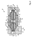
- the valve unit 86 is designed as a double anchor solenoid valve. The structural design results from Fig. 2 showing the double anchor solenoid valve 134.
- the double anchor solenoid valve 134 has two arranged in a common armature guide assembly 136 armature 138, 140. It is designed as an armature guide tube, wherein the inner tube diameter is at least partially constant in sections and adapted to the outer diameter of the armature 138, 140.
- a first magnet armature namely the primary armature 138
- a spring 142 is shown in FIG Fig. 2 therefore pressed to the right.
- a second armature namely the secondary armature 140 is loaded with a spring 144, which magnet armature 140 in the in Fig. 2 shown representation pushes to the left.
- the armature guide assembly 136 is surrounded by a solenoid 146.
- the outer diameter of the armature guide assembly 136 is matched to the inner diameter of the solenoid 146.
- the magnet coil 146 pulls the primary armature 138 and possibly the secondary armature 140 in the direction of the coil interior.
- the primary anchor 138 is used as a switching element for a venting valve 148 (FIG. Fig. 1 ) and the secondary armature 140 are provided as a switching element for a ventilation valve 150.
- the magnetic coil 146 has two electrical connections 152, which are connected to the electrical control unit 40 by means of the electrical lines 118.
- both the primary anchor 138 and the secondary armature 140 are in their designated by the springs 142, 144, in the Fig. 1 to 3 illustrated basic positions.
- the vent valve 150 shuts off in its basic position, the first port 122 from the third port 132 and the vent valve 148 connects in its normal position the second port 128 to the third port 132 with the interposition of an aperture acting as throttle 154.
- a compressed air reservoir 158 is provided between the aperture 154 and one by means of Primärankers 138 switchable outlet 160 of the vent valve 148. This compressed air reservoir 158 is formed as a chamber within the valve unit 86.
- the outlet 160 of the vent valve 148 is connected to the second port 128 of the valve unit 86. Further, the vent valve 148 has an inlet 162 which is connected to the third port 132 via respective connection channels within the valve unit 86.
- this inlet 162 is pneumatically connected to the second port 128 via the compressed air reservoir 158 and the diaphragm 154. Furthermore, in the basic position of the primary anchor 138, the second outlet 160 is shut off. In a switch position of the primary anchor 138, i. when the primary armature is drawn by feeding a first magnetic current of a predetermined height toward the interior of the solenoid 146, the compressed air reservoir 158 is pneumatically connected to the second outlet 160 and the inlet 162 is shut off.
- An elastomeric insert 164, 166 is provided at each end of the primary anchor 138.
- the elastomeric inserts 164, 166 may also be integrally formed by the primary anchor 138 having a continuous bore through which the elastomeric insert 164, 166 passes.
- the elastomer inserts 164, 166 each form a valve seat with a corresponding formations 168 on the armature guide assembly 136 and a molding 170 on a venting valve head 172, respectively.
- the vent valve 150 has an inlet 174 connected to the first port 122 of the valve unit 86 and an outlet 176 connected to the third port 132.
- the outlet 176 is also pneumatically connected to the inlet 162 of the vent valve via respective channels in the valve unit 86.
- the secondary armature 140 of the ventilation valve 150 shuts off the inlet 174 of the ventilation valve 150 from its outlet 176 in its basic position. In its switching position, the secondary arm 140 connects the inlet 174 with the outlet 176.
- the secondary anchor 140 has an elastomer insert 178, 180 at its two ends. These elastomer inserts can either be separate or, as in Fig. 2 represented, integrally formed. In the case of integral formation, the elastomeric insert passes through a passageway passing through the secondary anchor. The elastomer inserts 178, 180 protruding at both ends of the secondary anchor 140 may come into contact with corresponding formations 182, 184 on a vent valve head 186 and on the armature guide assembly 136, respectively. By means of the elastomeric insert 178 and the molding 182, a valve seat is formed, whereby the inlet 174 of the venting valve 150 can be shut off.
- the stop between the elastomer insert and the molding 184 always remains open. Furthermore, this stop is pneumatically connected via a channel-like passage 188 to the inlet 162 of the vent valve.
- the primary anchor 138 and the secondary armature 140 are each formed substantially rotationally symmetrical. However, they each have a groove-like recess 190 or 192 extending along the respective armature.
- the recess 190 of the primary anchor 138 provides communication between the inlet 162 of the vent valve and the compressed air reservoir 158 when the primary anchor 138 is in its home position.
- the recess 192 of the secondary anchor 140 creates a connection between the recess 187 or the passage 188 and the outlet of the ventilation valve 176, regardless of the switching position of the secondary anchor 140. Due to the described arrangement, the vent valve 148 forms a 3/2-way solenoid valve. The vent valve 150 forms a 2/2-way solenoid valve.
- Fig. 3 is largely the same as in Fig. 2 shown valve unit and is therefore designated by the reference numeral 86 '. Therefore, only the differences from the valve unit 86 will be explained below. All other elements are identical and / or functionally identical, as in connection with Fig. 3 explained. In this respect, reference is made to the above statements.
- valve unit 86 ' differs from the in Fig. 2 shown valve unit 86 on the one hand by the formation of the armature guide assembly 136 'and on the other hand by the formation of the secondary armature 140'.
- the secondary arm 140 ' is formed with a smaller diameter than that in FIG Fig. 2 shown Sekundäranker 140. This results in a particularly space-saving arrangement.
- This also makes it possible to design the armature guide arrangement 136 'in the region of the secondary armature 140' in a slimmer manner.
- the secondary arm 146 'facing the end of the armature guide assembly 136' is formed of uniform cross-section.
- the armature guide assembly 136 'thus has an outer contour corresponding to the inner contour of the solenoid 146, and over substantially the entire length of the armature guide assembly 136'; Only at its end associated with the primary anchor 138 does the armature guide arrangement 136 'have a projection or a thickening.
- armature guide assembly 136 ' Due to this design of the armature guide assembly 136 ', a simple assembly of the valve unit 86' is possible because the armature guide assembly 136 'from one side, namely in the in Fig. 3 shown orientation from the right side, can be mounted. Moreover, the different diameters of primary and secondary anchors result in an improvement in the switching performance of the valve unit 86 '.
- Fig. 4 shows a further embodiment of a parking brake module 14 ', which largely corresponds to the in Fig. 1 Parking brake module 14 shown corresponds. This in Fig. 4 However, shown parking brake module 14 'shows only the valve unit 86 for the towing vehicle. In Fig. 4 Therefore, like reference numerals designate like parts as in FIG Fig. 1 , so that in turn reference is made to the above statements.
- the spring accumulator 30 is to be vented slowly through the aperture 154.
- the control volume of the relay valve 64 and 64 ' is very small, a venting of the control input 82 of the relay valve 64, 64' may only take place via a very small aperture 154. Therefore, the aperture 154 per se would be designed with a very small diameter. A very small diameter, however, carries the risk that it clogged by contamination or icing. However, due to contamination or icing, the throttled venting could be ineffective and thus a safe venting of the spring-loaded part 30 of the spring brake cylinder could no longer be guaranteed.
- the control volume of the relay valve will appear to be, i. virtually increased by providing a connection between the control input 82 and the outlet 80 of the relay valve 64 '.
- This connection is formed, for example, in the form of a perforation 194 forming through hole of the relay piston.
- This aperture 194 increases the amount of air to be vented in the control chamber of the relay valve 64 '. In this way, despite a sufficiently large opening of the aperture 154 - to reduce the risk of contamination or icing - the working volume at the control input 82 of the relay valve 64 'are vented sufficiently slowly.
- the aperture 194 of the relay piston of the relay valve 64 'advantageously has a larger cross-sectional area than the cross-sectional area of the aperture 154 of the valve unit 86.
- the pressure at the control input 82 corresponds of the relay valve 64 'substantially the pressure at the outlet 80 of the relay valve 64'. Venting of the spring-loaded part 30 is thus no longer or only to an insignificant part via the vent port 88 of the relay valve 64 'instead. Rather, essentially the entire volume of the spring-loaded part 30 and the control volume at the control input 82 of the relay valve 64 'are vented via the orifice 154 and, because of the small opening of the orifice 154, sufficiently slow.
- a valve unit Due to the double anchor valve according to the invention with a shutter for slow venting a valve unit is provided which is simple in construction and therefore designed cost-effective and at the same time ensures safe parking of the vehicle even in case of failure of the electrical energy supply.
- the relay valve and thus the spring accumulator part of the spring brake cylinder can be vented.
- the pressure at the control input of the relay valve and thus also in the spring storage part of the spring brake cylinder can be maintained.
- rapid priming and rapid priming will allow fast venting. In the de-energized state, however, only a slow venting of the control chamber of the relay valve via a panel occurs.
- the invention allows a simple realization of a parking brake, which ensures a safe state even in case of failure of the electrical power supply and also can be operated in a purely electrical way;
- the often previously common pneumatic piping in the cab can be omitted to activate the parking brake and completely an operation of the parking brake can be achieved via an electric actuator.
Landscapes
- Engineering & Computer Science (AREA)
- Mechanical Engineering (AREA)
- Transportation (AREA)
- Physics & Mathematics (AREA)
- Electromagnetism (AREA)
- Fluid Mechanics (AREA)
- General Engineering & Computer Science (AREA)
- Valves And Accessory Devices For Braking Systems (AREA)
- Magnetically Actuated Valves (AREA)
- Braking Systems And Boosters (AREA)
- Regulating Braking Force (AREA)
Description
- Die Erfindung betrifft eine Ventileinheit für eine elektropneumatische Bremssteuerungseinrichtung zur Steuerung einer Fahrzeugbremse nach dem Oberbegriff des Anspruchs 1. Ferner betrifft die Erfindung gemäß Anspruch 14 eine zur Steuerung der Feststellbremse eines Fahrzeugs vorgesehene elektropneumatische Bremssteuerungseinrichtung mit einer derartigen Ventileinheit. Des Weiteren betrifft die Erfindung gemäß Anspruch 17 eine elektrisch gesteuerte pneumatische Fahrzeugbremsanlage mit einer derartigen Bremssteuerungseinrichtung. Schließlich betrifft die Erfindung gemäß Anspruch 18 ein Fahrzeug mit einer derartigen elektrisch gesteuerten pneumatischen Bremsanlage.
- Ventileinrichtungen für elektropneumatische Bremssteuerungseinrichtungen zur Steuerung von Fahrzeug-Feststellbremsen sind bspw. aus
DE 103 36 611 A1 oderEP 1 571 061 A1 bekannt. Diese bekannten Bremssteuerungseinrichtungen werden in Bremsanlagen eingesetzt, die neben einer mittels eines Bremspedals betätigbaren Betriebsbremse eine Feststellbremse (oftmals auch als Parkbremse oder Handbremse bezeichnet) aufweisen, welche mittels eines elektrischen Signalgebers betätigbar ist. - Die Feststellbremse wird bei diesen bekannten Bremsanlagen regelmäßig mittels als Federspeicherbremszylinder ausgebildeten Bremszylindern eingelegt. Um die Feststellbremse zu lösen, muss der Federspeicherteil der Federspeicherbremszylinder mit Druckluft beaufschlagt werden. Hierzu ist ein Belüften des Federspeicherteils erforderlich. Der notwendige Druck zum Belüften wird aus einem Druckluftvorrat zugeführt. Diese Druckzufuhr ist jedoch nicht permanent eingeschaltet, sondern kann auch abgesperrt werden. Ferner kann auch der Druck im Federspeicherbremszylinder abgesenkt, der Federspeicherteil also entlüftet werden.
- Zur Steuerung des Druckes im Federspeicherbremszylinder ist herkömmlicherweise ein Relaisventil vorgesehen, mittels dessen die Druckzufuhr von dem Druckluftvorratsbehälter zum Federspeicherteil der Federspeicherbremszylinder steuerbar ist. Die Steuerung erfolgt unter Zuhilfenahme elektropneumatischer Ventileinrichtungen, insbesondere mittels elektrisch betätigbarer Magnetventile, die einen am Relaisventil zugeführten Steuerdruck regulieren.
- Bei einer bekannten Bremsanlage gemäß
DE 103 36 611 A1 wird hierzu ein Bistabilventil eingesetzt, d.h. ein Ventil, das zwei stabile Zustände einnehmen kann und im Falle eines Stromausfalls den momentan eingestellten Zustand behält. Ferner ist bei dieser Bremsanlage zwischen das Bistabilventil und den Steuereingang des Relaisventils ein Haltenventil geschaltet. Mittels des Bistabilventils und des Haltenventils kann der Druck am Steuereingang entweder gehalten, erhöht oder abgesenkt werden. In entsprechender Weise verändert sich der Druck am Ausgang des Relaisventils. Auf diese Weise kann mittels elektrischer Signale an das Bistabilventil und das Haltenventil die Feststellbremse gelöst oder eingelegt werden. - Das Bistabilventil ist jedoch aufgrund seines Aufbaus kompliziert und daher teuer. Ferner verbleibt das Bistabilventil, wie oben erwähnt, bei einem Ausfall der elektrischen Energieversorgung in seinem vorherigen Zustand. Daher kann bei einem Ausfall der elektrischen Energieversorgung ein Fahrzeug mit einer derartigen Bremsanlage nicht sicher abgestellt werden, d.h. nicht derart abgestellt werden, dass der Federspeicherteil des Federspeicherbremszylinders entlüftet und dadurch die Feststellbremse einlegt ist.
- Zwar wurden bereits in
DE 35 01 708 A1 elektromagnetisch betätigbare Mehrwegeventile vorgeschlagen, die in ihrem Aufbau weniger kompliziert sind. Insbesondere wurde vorgeschlagen, in einem Mehrwegeventil zwei einander gegenüberliegend angeordnete Ventile anzuordnen. Dabei ist jedem der beiden Ventile je ein Anker zugeordnet, welche mit einer zwischen den beiden Ventilen angeordneten Spule zusammenwirken. Die den Ankern zugeordneten Federn sind dabei derart ausgelegt, dass unterschiedliche Magnetkräfte zur Betätigung der beiden Ventile erforderlich sind. Diese Magnetkräfte werden durch Anlegen eines durch die Spule fließenden Stromes erzeugt. Indem jedem Ventil ein separater Anker zugeordnet ist, wird eine voneinander unabhängige Betätigung der beiden Ventile durch entsprechende Bestromung der Spule ermöglicht. - Diese bekannte Ventileinheit hat jedoch den Nachteil, dass im unbestromten Zustand der Eingang der Ventileinheit mit dem zum Verbraucher führenden Ausgang verbunden ist. Würde man eine derartige Ventileinheit anstelle des o.g. Bistabilventils und Haltenventils verwenden, würde im Falle eines Ausfalls der elektrischen Energieversorgung der volle Vorratsdruck auf den Steuereingang des Relaisventils angewendet und somit infolge der sich daraus ergebenden Belüftung des Federspeicherteils der Federspeicherbremszylinder die Feststellbremse gelöst werden. Dies ist jedoch unerwünscht, da im Falle eines Ausfalls der elektrischen Energieversorgung das Fahrzeug nicht mehr sicher abgestellt werden kann. Diese bekannten Ventile sind daher ungeeignet für die Steuerung des Druckes in einem Federspeicherbremszylinder einer Feststellbremse.
-
WO 2006/007970 A1 offenbart eine Ventilsteuereinrichtung für eine elektronischpneumatische Bremsanlage, bei der jeweils eine Ventileinheit als Ventil-Modulator-Einrichtung für einen Bremsdruckregelkreis ausgebildet ist. Die Ventileinheit ist aus einem Belüftungsventil mit einem Primäranker und einem Entlüftungsventil mit einem Sekundäranker aufgebaut. Für beide Magnetanker ist eine gemeinsame Ankerführung vorgesehen sowie eine Steuerung durch den Magnetstrom einer gemeinsamen Magnetspule. - Der Erfindung liegt daher die Aufgabe zugrunde, eine einfache, günstige Ventileinheit für eine elektropneumatische Bremssteuerungseinrichtung zur Steuerung einer Feststellbremse bereitzustellen, welche auch im Falle eines Ausfalls der elektrischen Spannungsversorgung ein sicheres Abstellen des Fahrzeugs ermöglicht.
- Diese Aufgabe wird durch die in den Patentansprüchen 1, 14, 17 und 18 angegebene Erfindung gelöst.
- Die erfindungsgemäße Ventileinheit ist derart ausgebildet, dass im unbestromten Zustand keine Belüftung einer luftmengenverstärkenden Ventileinrichtung erfolgt, sondern eine Entlüftung. Daher wird auch im Falle eines Ausfalls der elektrischen Energieversorgung der Steuereingang der luftmengenverstärkenden Ventileinrichtung permanent entlüftet. Am Ausgang der luftmengenverstärkenden Ventileinrichtung ist ein Feststellbremssystem mit Federspeicherbremszylindern anschließbar. Derartige Federspeicherbremszylinder sind derart ausgebildet, dass sie im entlüfteten Zustand bremsen und lediglich im belüfteten Zustand die Federspeicherbremszylinder die Feststellbremse lösen. Auf diese Weise ist sichergestellt, dass auch im Falle eines Ausfalls der elektrischen Energieversorgung die Federspeicherbremszylinder der Feststellbremse entlüftet und damit die Feststellbremse eingelegt wird.
- Durch die als Doppelankermagnetventil vorgesehene Ventileinheit können mit nur einer Spule zwei Ventile, nämlich ein Belüftungsventil und ein Entlüftungsventil betätigt werden. Hierdurch verringert sich zum einen der Aufwand beim Aufbau der Ventileinheit. Zum anderen verringert sich der Aufwand bei der Kontaktierung und bei der elektrischen Ansteuerung der Ventileinheit, da lediglich zwei Anschlüsse für die Magnetspule erforderlich sind. Ebenso reduziert sich die Anzahl der benötigten Endstufen zum Bestromen dieses Magnetventils, einschl. der zu den Endstufen gehörenden Bauteile. Ferner wird die gesamte Stromaufnahme durch die Verwendung lediglich einer Spule für zwei Ventile reduziert. Hieraus folgt ein günstigeres Wärmeverhalten der Bremssteuerungseinrichtung.
- Des weiteren ergibt sich eine kompakte Bauweise der Ventileinheit gegenüber einer herkömmlichen Ventileinrichtung bestehend aus einem Bistabilventil und einem Haltenventil. Aufgrund der kompakteren Bauweise sowie der geringeren Anzahl von Bauteilen können ferner auch die Herstellkosten signifikant reduziert werden.
- Im vorliegenden Zusammenhang ist der Begriff "Verbindungsorgan" derart zu verstehen, dass er jedwede Verbindungsmittel umfasst, wie insbesondere pneumatische Verbindungsleitungen, Verbindungskanäle, Verbindungsbohrungen oder sonstige Durchgänge sowie Verbindungsanschlüsse, insbesondere Anschlüsse für pneumatische Verbindungsleitungen, -kanäle, und -bohrungen.
- Die Ventileinheit ist entweder als selbstständige Vorrichtung oder als unselbstständiger, integraler Teil einer Bremssteuerungseinrichtung ausgebildet.
- Bei stromloser Magnetspule befinden sich sowohl der Primäranker als auch der Sekundäranker des Doppelankermagnetventils in einer durch entsprechende Federn vorgegebenen Grundstellung, in der das Entlüftungsventil des Doppelankermagnetventils eine Entlüftung des Steuereingangs der luftmengenverstärkenden Ventileinrichtung aktiviert, insbesondere indem ein zum Steuereingang der luftmengenverstärkenden Ventileinrichtung führendes Verbindungsorgan, das sog. dritte Verbindungsorgan, mit einem zu einer Entlüftungseinrichtung führenden Verbindungsorgan, dem sog. zweiten Verbindungsorgan, verbunden wird. Der Steuereingang ist auf diese Weise entlüftbar. Zugleich befindet sich das Belüftungsventil in seiner Grundstellung und zwar derart, dass eine Belüftung des Steuereingangs der luftmengenverstärkenden Ventileinrichtung abgesperrt wird, insbesondere indem ein zum Druckluftvorrat führendes erstes Verbindungsorgan der Ventileinheit vom dritten Verbindungsorgan zum Steuereingang der luftmengenverstärkenden Ventileinrichtung abgesperrt wird. Auf diese Weise wird dem Steuereingang keine weitere Druckluft zugeführt. Im stromlosen Zustand findet somit eine permanente, insbesondere gedrosselte Entlüftung des Steuereingangs der luftmengenverstärkenden Ventileinrichtung und somit über die luftmengenverstärkende Ventileinrichtung eine Entlüftung der Federspeicherbremszylinder statt. Auf diese Weise ist sichergestellt, dass die Feststellbremse eingelegt wird.
- Bei Einspeisung eines ersten niedrigen Stroms in die Magnetspule wird zunächst nur der Primäranker und somit das Entlüftungsventil der Ventileinheit bestromt und auf diese Weise in seine Schaltstellung versetzt. Bei diesem niedrigen Strom verbleibt jedoch der Sekundäranker in seiner federbelasteten Grundstellung. In der Schaltstellung des Primärankers wird mittels des Entlüftungsventils die Entlüftung des Steuereingangs der luftmengenverstärkenden Ventileinrichtung abgesperrt, insbesondere indem das zur Entlüftungseinrichtung führende zweite Verbindungsorgan vom zum Steuereingang führenden dritten Verbindungsorgan abgesperrt wird. Auf diese Weise kann der Druck am Steuereingang auf seinem aktuellen Wert gehalten werden. Durch Einspeisung eines höheren Stromes in die Magnetspule wird dann auch der Sekundäranker in seine Schaltstellung versetzt, so dass das Belüftungsventil die Belüftung des Steuereingangs der luftmengenverstärkenden Ventileinrichtung aktiviert. Dabei verbindet insbesondere das Belüftungsventil das zum Druckluftvorrat führende erste Verbindungsorgan mit dem zum Steuereingang führenden dritten Verbindungsorgan. Durch diese Verbindung wird die luftmengenverstärkende Ventileinrichtung belüftet und in der Folge der Federspeicherteil des Federspeicherbremszylinders. In diesem Zustand wird die Feststellbremse gelöst, so dass das Fahrzeug in einen Fahrzustand versetzt wird.
- Bevorzugterweise verbindet bei stromloser Magnetspule das Entlüftungsventil das zweite zur Entlüftungseinrichtung führende Verbindungsorgan mit dem dritten zum Steuereingang der luftmengenverstärkenden Ventileinrichtung führenden Verbindungsorgan über eine Blende bzw. Drossel. Auf diese Weise ist der Steuereingang der luftmengenverstärkenden Ventileinrichtung gedrosselt entlüftbar. Dies hat den Vorteil, dass das Fahrzeug auch bei einem Ausfall der elektrischen Energieversorgung, insbesondere der Bremssteuerungseinrichtung langsam eingebremst wird und sicher abgestellt werden kann. Erreicht wird dies durch eine als Drossel wirkende Blende am Entlüftungsventil der Ventileinheit, welche in stromlosen Zustand der Magnetspule wirksam ist. D.h. der Druck am Steuereingang einer luftmengenverstärkenden Ventileinrichtung wird langsam über diese Blende abgesenkt, so dass auch der Druck im Federspeicherteil des Federspeicherbremszylinders langsam absinkt und somit die Feststellbremse langsam eingelegt wird.
- Besonders bevorzugt wird die Magnetspule mit einem alternierenden Magnetstrom insbesondere einem getakteten Magnetstrom beaufschlagt, wobei dieser alternierende Strom derart bemessen ist, dass der Primäranker getaktet betätigt wird, während der Sekundäranker unbetätigt in seiner Grundstellung verbleibt. Auf diese Weise kann eine schnelle Entlüftung des Steuerraums der luftmengenverstärkenden Ventileinrichtung erzielt werden. Durch ein schnelles Hin- und Herschalten des Entlüftungsventils zwischen seiner Grundstellung und seiner Schaltstellung gelangt nämlich Druckluft aus dem Steuerraum der luftmengenverstärkenden Ventileinrichtung zunächst an einen ersten Auslass des Entlüftungsventils, der jedoch mit der Drossel des Entlüftungsventils verbunden ist. Daher kann die Druckluft über diesen Weg eigentlich nicht schnell entweichen. Aufgrund des sich unmittelbar anschließenden Umschaltens des Entlüftungsventils in seine Schaltstellung wird jedoch die sich nunmehr vor der Drossel befindende Druckluft direkt über einen entsprechenden Weg bzw. Kanal im Entlüftungsventil zu einer Entlüftungseinrichtung entlassen. Die bei einem einzelnen Schaltvorgang entweichende Luftmenge ist bei einem einzelnen Schaltvorgang des Entlüftungsventils zwar nicht allzu groß und hängt von einem zur Verfügung gestellten Volumen ab. Jedoch kann durch häufiges und schnelles Hin- und Herschalten eine schnelle Entlüftung des Steuerraums der luftmengenverstärkenden Ventileinrichtung erreicht werden. Vorteilhafterweise ist zu diesem Zweck zwischen der Blende und einem Auslass des Entlüftungsventils ein Druckluftspeicher vorgesehen, um die zu entlassene Luftmenge zu vergrößern.
- Bei einer bevorzugten Ausführungsform springt der alternierende Magnetstrom zwischen dem Wert Null und einem der Stärke des o.g. ersten Magnetstroms entsprechendem Wert hin und her. Diese Ausführungsform hat den Vorteil, dass dieser erste Magnetstrom lediglich getaktet, d.h. ein- und ausgeschaltet werden muss. Alternativ kann der alternierende Magnetstrom aber auch zwischen zwei dichter beieinander liegenden Stromwerten erzeugt werden, wodurch die Schaltstellungen des Primärankers schneller gewechselt werden können.
- Bei einer weiteren bevorzugten Ausführungsform weisen der Primäranker und der Sekundäranker unterschiedliche Durchmesser auf. Insbesondere weist der Sekundäranker einen kleineren Durchmesser auf als der Primäranker. Hierdurch ergibt sich erstens der Vorteil, dass die Konstruktion der Ankerführungsanordnung derart gestaltet werden kann, dass das Ankerführungsrohr samt der beiden Magnetanker von einer Seite in die Spule montierbar ist. Zweitens ergibt sich der Vorteil, dass aufgrund der unterschiedlichen Größen, insbesondere Durchmesser der Anker unterschiedliche Magnetkräfte auf die Anker wirken. Hierdurch kann das Schaltverhalten der Ventileinheit günstig beeinflusst werden. Wie vorstehend ausgeführt, soll nämlich zunächst der Primäranker von der Magnetspule und erst bei einem höheren Strom auch der Sekundäranker angezogen werden.
- Vorteilhafterweise tauchen der Primäranker und der Sekundäranker unterschiedlich tief in die Magnetspule ein. Insbesondere taucht der Primäranker tiefer in die Magnetspule ein als der Sekundäranker. Dies hat den Vorteil, dass die von der Magnetspule auf den Primäranker ausgeübte Magnetkraft größer ist als die von der Magnetspule auf den Sekundäranker ausgeübte Magnetkraft. Auch hierdurch wird das Schaltverhalten der Ventileinheit günstig beeinflusst.
- Bei einer weiteren vorteilhaften Ausführungsform ist die auf den Primäranker ausgeübte Federkraft einer zugeordneten Feder kleiner als die auf den Sekundäranker ausgeübte Federkraft einer weiteren, dem Sekundäranker zugeordneten Feder. Vorteilhafterweise werden hierzu Federn unterschiedlicher Stärke verwendet. Auch diese Maßnahme verbessert das Schaltverhalten des Magnetventilsystems.
- Bei einer weiteren Ausführungsform sind der Primäranker und der Sekundäranker baugleich ausgeführt. Dies hat den Vorteil, dass aufgrund größerer Stückzahlen die Herstellkosten dieser Anker reduziert werden können.
- Weitere vorteilhafte Ausführungsformen ergeben sich aus den Unteransprüchen sowie aus den anhand der beigefügten Zeichnungen näher erläuterten Ausführungsbeispielen. In der Zeichnung zeigt:
- Fig. 1
- eine Druckluftbremsanlage in vereinfachter schematischer Darstel- lung mit einer elektropneumatischen Bremssteuerungseinrichtung zur Steuerung einer Feststellbremse einschließlich zweier Ventileinheiten gemäß einem Ausführungsbeispiel der Erfindung;
- Fig. 2
- eine Ventileinheit gemäß einem Ausführungsbeispiel der Erfindung für eine Bremssteuerungseinrichtung gemäß
Fig. 1 ; - Fig. 3
- eine Ventileinheit gemäß einem weiteren Ausführungsbeispiel der Erfindung für eine Bremssteuerungseinrichtung gemäß
Fig. 1 und - Fig. 4
- eine schematische Darstellung einer Bremssteuerungseinrichtung für eine Feststellbremse einschließlich einer Ventileinheit gemäß einem weiteren Ausführungsbeispiel der Erfindung.
-
Fig. 1 zeigt schematisch einen Teil einer Druckluftbremsanlage 10 für ein Fahrzeug und zwar insbesondere eine elektropneumatische Bremssteuerungseinrichtung zur Steuerung einer Feststellbremse des Fahrzeugs. Derartige Druckluftbremsanlagen werden bspw. bei Nutzfahrzeugen, Lastkraftwagen oder Bussen verwendet. Besondere Anwendung finden derartige Bremsanlagen bei Fahrzeugzügen bestehend aus einem Zugfahrzeug und einem Anhänger. -
Fig. 1 zeigt lediglich die zum Verständnis der vorliegenden Erfindung wichtigsten Komponenten der Bremsanlage 10. Die Bremsanlage 10 wird elektrisch gesteuert, d.h. die Bremsdruckzumessung zu Bremszylindern zur Betätigung von an den Fahrzeugrädern vorgesehenen Radbremsen wird durch elektrische bzw. elektronische Steuerelemente gesteuert. Die Bremszylinder sind teilweise oder vollständig als kombinierte Betriebs- und Federspeicherbremszylinder 12 (inFig. 1 ist der Übersichtlichkeit halber lediglich ein derartiger Bremszylinder dargestellt) ausgebildet, wobei der Federspeicherteil von einer als Feststellbremsmodul 14 ausgebildeten elektropneumatischen Bremssteuerungseinrichtung zur Steuerung der Feststellbremse gesteuert wird. - Die Bremsanlage 10 weist einen Bremswertgeber 16 auf, der einen Bremswunsch des Fahrers erfasst. Der Bremswertgeber 16 umfasst einen elektrischen Teil und einen pneumatischen oder hydraulischen Teil, wobei in
Fig. 1 lediglich der pneumatische Teil dargestellt ist. Der pneumatische Teil wird von einem ersten Druckluftvorratsbehälter 18 und einem zweiten Druckluftvorratsbehälter 20 mit Druckluft über (nicht dargestellte) Druckluftleitungen versorgt. Diese Druckluftvorratsbehälter 18, 20 dienen der Druckluftversorgung der Bremszylinder der Betriebsbremse. Sie können aber auch, wie inFig. 1 veranschaulicht, der Druckluftversorgung der Feststellbremse dienen. Alternativ kann die Druckluft für die Feststellbremse von einem separaten Druckluftvorratsbehälter zugeführt werden. - Durch Betätigung eines Bremspedals 22 erzeugt der Bremswertgeber 16 entweder durch elektrische Ansteuerung von elektropneumatischen Einrichtungen oder direkt eine pneumatische Stellgröße, die über eine Druckluftleitung 24, 26 an den kombinierten Betriebs- und Federspeicherbremszylinder 12 geleitet wird.
- Der kombinierte Betriebs- und Federspeicherbremszylinder 12 ist als kombinierter Federspeicher-/Membranzylinder ausgebildet. Er weist neben der Funktion eines Membranzylinders zusätzlich eine Federspeicherfunktion auf. Dieser Bremszylinder 12 weist daher einen Membranteil 28, welcher pneumatisch mit der Betriebsbremsanlage verbunden sowie mit dem eigentlichen Bremsdruck beaufschlagbar ist, und einen Federspeicherteil 30 auf, welcher pneumatisch von dem Membranteil 28 getrennt und über gesonderte Druckluftleitungen 32, 34 mit Druckluft beaufschlagbar ist. Der Federspeicherteil 30 bildet einen Teil der Feststellbremse. Der Federspeicherteil 30 beinhaltet die Federspeicherfunktion, welche bei Druckbeaufschlagung des Federspeicherteils 30 eine Speicherfeder vorspannt und dabei eine Bremswirkung der Federspeicherfunktion verhindert bzw. verringert, während sich bei Entlüftung des Federspeicherteils 30 die Speicherfeder entspannt und dabei eine Bremswirkung im Rahmen der Federspeicherfunktion auf die mit dem jeweiligen Bremszylinder verbundene Bremse ausübt. Bremszylinder dieses Typs werden im vorliegenden Zusammenhang als Federspeicherbremszylinder bezeichnet.
- Zur Vermeidung einer mechanischen Überbeanspruchung der Bremsmechanik ist ein als Wechselventil bzw. Select-High-Ventil ausgebildeter, Überlastschutzventil 35 vorgesehen, das zwischen den Federspeicherteil 30, einen pneumatischen Ausgang 102 des Feststellbremsmoduls 14 und den den ausgesteuerten Druck aufweisenden Ausgang des Bremswertgebers 16 geschaltet ist. Dieses Überlastschutzventil 35 wählt den höheren der beiden Drücke, nämlich des ausgesteuerten Bremsdrucks am Ausgang des Bremswertgebers 16 bzw. des von der luftmengenverstärkenden Ventileinrichtung 64 zur Verfügung gestellten Druckes, aus und führt diesen dem Federspeicherteil 30 des Federspeicherbremszylinders 12 zu. Dieses Überlastschutzventil 35 verhindert eine Addition der von der Betriebsbremse, d.h. über den pneumatischen Teil bzw. Membranteil 28 zugeführten Bremskraft mit der von der Feststellbremse, d.h. dem Federspeicherteil 30 zugeführten Bremskraft, um auf diese Weise eine mechanische Überbeanspruchung der Bremsmechanik der diesem Bremszylinder zugeordneten Radbremse zu vermeiden. Die dem Bremszylinder über den Membranteil 28 zugeführte Bremskraft wird durch die dargestellte Konstruktion nicht um die von dem Federspeicherteil 30 ausgeübte Bremskraft erhöht, da im Falle einer Betätigung der Betriebsbremse die von der Speicherfeder ausgeübte Bremskraft um eine der Betätigung der Betriebsbremse entsprechende Kraft reduziert wird. Somit kann eine kritische Überbeanspruchung der entsprechenden Radbremse vermieden werden.
- Mittels des Federspeicherbremszylinders wird eine Feststellbremsfunktion realisiert, die auch bei Fehlen von Druckluft eine Bremsung bzw. ein Feststellen des Fahrzeuges ermöglicht. Die Feststellbremsfunktion ist aktiv, wenn der jeweilige Federspeicherteil 30 des Federspeicherbremszylinders 12 unterhalb eines Mindestdruckwertes entlüftet wird. Der Federspeicherteil 30 des Bremszylinders 12 ist über die Druckluftleitungen 32, 34 mit dem Feststellbremsmodul 14 pneumatisch verbunden, welches eine Drucksteuerung mit Hilfe elektronischer Steuerungsmittel erlaubt.
- Ein manuell betätigbarer Feststellbremssignalgeber 36 ist über eine mehradrige elektrische Leitung 38 mit einer elektrischen Steuereinheit 40 des Feststellbremsmoduls 14 elektrisch verbunden.
- Die elektrischen Einrichtungen im Fahrzeug werden von einer nicht dargestellten elektrischen Energieversorgungseinrichtung, z.B. einer Fahrzeugbatterie, über entsprechende elektrische Leitungen mit Energie versorgt.
- Das Fahrzeug ist zur Ankopplung eines Anhängers mit einer weiteren mit Federspeicherbremszylindern ausgestalteten Feststellbremse geeignet. Die Bremsanlage 10 weist daher ein sog. Zugwagenschutzventil 42 auf, welches zur Bremsdrucksteuerung, insbesondere der Feststellbremse des Anhängers dient. Das Zugwagenschutzventil 42 wird über Druckluftleitungen 44, 46 mit dem Vorratsdruck der Druckluftvorratsbehälter 18, 20 versorgt. Ferner wird dem Zugwagenschutzventil 42 ein mittels einer luftmengenverstärkenden Ventileinrichtung, nämlich einem Relaisventil 48, für die Feststellbremse des Anhängers vorgesehener ausgesteuerter Druck bereitgestellt.
- Das Relaisventil 48 weist einen Steuereingang 50, einen mittelbar oder unmittelbar mit der Atmosphäre verbundenen Entlüftungsanschluss 52 sowie einen über eine Druckluftleitung 54 mit dem Vorratsdruck der Druckluftvorratsbehälter 18, 20 verbindbaren Einlass 56 sowie einen über eine Druckluftleitung 58 mit dem Zugwagenschutzventil 42 verbindbaren Auslass 60 auf. Der Steuereingang 50 ist über eine Druckluftleitung 62 mit dem Feststellbremsmodul 14 verbunden.
- Das Relaisventil 48 gibt an seinem Auslass 60 einen Ausgangsdruck in die Druckluftleitung 58 ab, der dem über die Druckluftleitung 62 an den Steuereingang 50 und somit dem in eine Steuerkammer des Relaisventils 48 eingesteuerten Druck entspricht. Das Relaisventil 48 entnimmt dabei die hierfür benötigte Druckluft aus der mit dem Einlass 56 des Relaisventils 48 verbundenen Druckluftleitung 54, die über weitere Druckluftleitungen mit den Druckluftvorratsbehältern 18, 20 verbunden ist.
- Das Feststellbremsmodul 14 weist eine luftmengenverstärkenden Ventileinrichtung in Form eines Relaisventils 64 für das Zugfahrzeug auf. Das Relaisventil 64 umfasst einen unmittelbar oder mittelbar über Druckluftleitungen 66 bis 75 mit den Druckluftvorratsbehältern 18, 20 verbundenen Einlass 76. Ferner weist das Relaisventil 64 einen über Druckluftleitungen 78, 34, 32 mit dem Federspeicherteil 30 des Bremszylinders 12 verbundenen Auslass 80 auf. Ferner weist das Relaisventil 64 einen Steuereingang 82 auf, der über eine Druckluftleitung 84 mit einer Ventileinheit 86 zur Steuerung der Feststellbremse des Zugfahrzeugs verbunden ist.
- Das Relaisventil 64 gibt an seinem Auslass 80 einen Ausgangsdruck in die Druckluftleitung 78 ab, der dem über die Druckluftleitung 64 an den Steuereingang 82 und somit einem in eine Steuerkammer des Relaisventils 64 eingesteuerten Druck entspricht. Das Relaisventil 64 entnimmt dabei die hierfür benötigte Druckluft aus der mit dem Einlass 76 des Relaisventils 64 verbundenen Druckluftzufuhrleitung 66. Eine etwaig notwendige Entlüftung der Druckluftleitung 78 erfolgt über einen mittelbar oder unmittelbar mit der Atmosphäre verbundenen Entlüftungsanschluss 88. Im in
Fig. 1 gezeigten Ausführungsbeispiel ist dieser Entlüftungsanschluss 88 über eine Druckluftleitung 90 mit einer Entlüftungseinrichtung 92 verbunden. - Das Feststellbremsmodul 14 weist ferner jeweils vor die Druckluftvorratsbehälter 18, 20 geschaltete Rückschlagventile 94, 96 auf, welche verhindern, dass im Falle eines Druckabfalls oder eines Abreißens oder einer Beschädigung der Druckluftleitungen 71 bzw. 75 zum Druckluftvorratsbehälter 20 bzw. 18 ein Druckverlust in dem Feststellbremsmodul 14 auftritt. Ein derartiger ungewollter Druckabfall bzw. Druckverlust ist nämlich unerwünscht, da er zu einem schlagartigen Einlegen der Feststellbremse und somit zu einer Notbremsung des Zugfahrzeuges führen würde. Dies kann unter Umständen eine unkontrollierbare Fahrsituation auslösen.
- Das Feststellbremsmodul 14 weist mehrere pneumatische Anschlüsse 98, 100, 102, 104, 106 auf. Über den Anschluss 98 wird die Druckluftleitung 74 mit der Druckluftleitung 75 zum Anschluss des ersten Druckluftvorratsbehälters 18 verbunden. Über den Anschluss 100 wird die Druckluftleitung 70 mit der Druckluftleitung 71 zum Anschluss des zweiten Druckluftvorratsbehälters 20 verbunden. Über den Anschluss 102 wird die Druckluftleitung 78 mit der Druckluftleitung 34 zur Verbindung des Relaisventils 64 mit dem Bremszylinder 12 verbunden. Über den Anschluss 104 wird die Druckluftleitung 44 zum Relaisventil 48 für die Anhängersteuerung mit einer Druckluftleitung 108 und somit über die Druckluftleitungen 67 bis 75 mit den Druckluftvorratsbehältern 18, 20 verbunden. Über den Anschluss 106 erfolgt eine Verbindung der Druckluftleitung 62 zum Steuereingang 50 des Relaisventils 48 für die Anhängersteuerung mit einer in dem Feststellbremsmodul 14 angeordneten Ventileinheit 110 zur Steuerung der Anhängerfeststellbremse.
- Das Feststellbremsmodul 14 weist ferner einen innerhalb eines Deckels 112 untergebrachten Drucksensor 114 auf, der zur Überwachung des Vorratsdruckes innerhalb des Feststellbremsmoduls 14 dient. Der Drucksensor 114 ist zu diesem Zweck über eine Druckleitung 116 mit der Druckleitung 72 und somit mit den Druckleitungen 66 bis 71, 73 bis 75 sowie 108, 44 und 46 unmittelbar oder mittelbar verbunden.
- Im Bereich des Deckels 112 ist ferner die bereits erwähnte elektrische Steuereinheit 40 angeordnet, mittels der über elektrische Leitungen 118, 120 die Ventileinheit 86 sowie die Ventileinheit 110 elektrisch schaltbar sind.
- Die Ventileinheiten 86 bzw. 110 sind baugleich ausgeführt. Nachfolgend beschränken wir uns daher auf die Erläuterung der Ventileinheit 86.
- Die Ventileinheiten 86 und 110 sind bei einer Ausführungsform als eigenständige Baugruppen ausgeführt. Alternativ sind die Ventileinheiten 86 und 110 jedoch entweder einzeln oder gemeinsam mit dem Relaisventil 64 und ggf. auch mit dem Relaisventil 48 integral in einem einzigen einheitlichen Feststellbremsmodul 14 realisiert. Bei einer Ausbildung der Ventileinheiten 86 bzw. 110 als selbstständige Bauteile weisen die Ventileinheiten nachfolgend näher ausgeführte pneumatische Anschlüsse auf. Sofern die Ventileinheiten jedoch in dem Feststellbremsmodul integriert sind, entfallen derartige Anschlüsse zugunsten entsprechender Verbindungsleitungen. In den Patentansprüchen ist daher der generische Begriff "Verbindungsorgan" verwendet, welcher jedwede Verbindungsmittel, d.h. sowohl Anschlüsse als auch anderweitige Verbindungen, wie Verbindungsleitungen, Verbindungskanäle oder -bohrungen und dergleichen mehr umfasst. In der nachfolgenden Beschreibung soll der Begriff "Anschluss" im Zusammenhang mit den Ventileinheiten 86 bzw. 110 somit auch als Verbindungsorgan verstanden werden, um auf diese Weise auch die Ausführungsform zu erläutern, bei der die Ventileinheiten 86 bzw. 110 im Feststellbremsmodul 14 integriert sind.
- Die Ventileinheit 86 weist einen ersten Anschluss 122 auf, der über Druckluftleitungen 126, 68 bis 75 mit den Druckluftvorratsbehältern 18, 20 verbunden ist. Die Ventileinheit 86 weist ferner einen zweiten Anschluss 128 auf, der über eine Druckluftleitung 130 mit der Entlüftungseinrichtung 92 verbunden ist. Die Ventileinrichtung 86 weist ferner einen dritten Anschluss 132 auf, der über die Druckluftleitung 84 mit dem Steuereingang 82 des Relaisventils 64 verbunden ist. Die Ventileinheit 86 ist als Doppelankermagnetventil ausgebildet. Die konstruktive Ausgestaltung ergibt sich aus
Fig. 2 , welches das Doppelankermagnetventil 134 zeigt. - Das Doppelankermagnetventil 134 weist zwei in einer gemeinsamen Ankerführungsanordnung 136 angeordnete Magnetanker 138, 140 auf. Sie ist als Ankerführungsrohr ausgebildet, wobei der innere Rohrdurchmesser zumindest teilweise abschnittsweise konstant und an die Außendurchmesser der Magnetanker 138, 140 angepasst ist. Ein erster Magnetanker, nämlich der Primäranker 138, ist mittels einer Feder 142 belastet und wird in der Darstellung gemäß
Fig. 2 daher nach rechts gedrückt. In entsprechender Weise ist ein zweiter Magnetanker, nämlich der Sekundäranker 140 mit einer Feder 144 belastet, welche den Magnetanker 140 in der inFig. 2 gezeigten Darstellung nach links drückt. Die Ankerführungsanordnung 136 ist von einer Magnetspule 146 umgeben. Der äußere Durchmesser der Ankerführungsanordnung 136 ist an den inneren Durchmesser der Magnetspule 146 angepasst. Bei Einspeisung geeigneter Magnetströme in die Magnetspule 146 zieht die Magnetspule 146 den Primäranker 138 und ggf. den Sekundäranker 140 in Richtung des Spuleninneren. Der Primäranker 138 ist als Schaltelement für ein Entlüftungsventil 148 (Fig. 1 ) und der Sekundäranker 140 als Schaltelement für ein Belüftungsventil 150 vorgesehen. Die Magnetspule 146 weist zwei elektrische Anschlüsse 152 auf, die mittels der elektrischen Leitungen 118 mit der elektrischen Steuereinheit 40 verbunden sind. - Bei stromloser Magnetspule 146 befinden sich sowohl der Primäranker 138 als auch der Sekundäranker 140 in ihren durch die Federn 142, 144 bestimmten, in den
Fig. 1 bis 3 dargestellten Grundstellungen. Das Belüftungsventil 150 sperrt in seiner Grundstellung den ersten Anschluss 122 vom dritten Anschluss 132 ab und das Entlüftungsventil 148 verbindet in seiner Grundstellung den zweiten Anschluss 128 mit dem dritten Anschluss 132 unter Zwischenschaltung einer als Drossel wirkenden Blende 154. Zwischen der Blende 154 und einen mittels des Primärankers 138 schaltbaren Auslass 160 des Entlüftungsventils 148 ist ein Druckluftspeicher 158 vorgesehen. Dieser Druckluftspeicher 158 ist als eine Kammer innerhalb der Ventileinheit 86 ausgebildet. - Der Auslass 160 des Entlüftungsventils 148 ist mit dem zweiten Anschluss 128 der Ventileinheit 86 verbunden. Ferner weist das Entlüftungsventil 148 einen Einlass 162 auf, der mit dem dritten Anschluss 132 über entsprechende Verbindungskanäle innerhalb der Ventileinheit 86 verbunden ist.
- In der Grundstellung des Primärankers 138 ist dieser Einlass 162 pneumatisch über den Druckluftspeicher 158 und die Blende 154 mit dem zweiten Anschluss 128 verbunden. Ferner ist in der Grundstellung des Primärankers 138 der zweite Auslass 160 abgesperrt. In einer Schaltstellung des Primärankers 138, d.h. wenn der Primäranker durch Einspeisung eines ersten Magnetstroms einer vorbestimmten Höhe in Richtung des Inneren der Magnetspule 146 hineingezogen ist, ist der Druckluftspeicher 158 mit dem zweiten Auslass 160 pneumatisch verbunden und der Einlass 162 abgesperrt.
- An beiden Enden des Primärankers 138 findet sich jeweils ein Elastomereinsatz 164, 166. Die Elastomereinsätze 164, 166 können auch einstückig ausgebildet sein, indem der Primäranker 138 eine durchgängige Bohrung aufweist, durch welche sich der Elastomereinsatz 164, 166 hindurchzieht. Die Elastomereinsätze 164, 166 bilden mit einer entsprechenden Ausformungen 168 an der Ankerführungsanordnung 136 bzw. einer Ausformung 170 an einem Entlüftungsventilkopf 172 jeweils einen Ventilsitz.
- Das Belüftungsventil 150 weist einen mit dem ersten Anschluss 122 der Ventileinheit 86 verbundenen Einlass 174 und einen mit dem dritten Anschluss 132 verbundenen Auslass 176 auf. Der Auslass 176 ist ferner mit dem Einlass 162 des Entlüftungsventils über entsprechende Kanäle in der Ventileinheit 86 pneumatisch verbunden.
- Der Sekundäranker 140 des Belüftungsventils 150 sperrt in seiner Grundstellung den Einlass 174 des Belüftungsventils 150 von seinem Auslass 176 ab. In seiner Schaltstellung verbindet der Sekundäranker 140 den Einlass 174 mit den Auslass 176.
- Der Sekundäranker 140 weist an seinen beiden Enden jeweils einen Elastomereinsatz 178, 180 auf. Diese Elastomereinsätze können entweder separat oder, wie in
Fig. 2 dargestellt, einstückig ausgebildet sein. Im Falle einer einstückigen Ausbildung tritt der Elastomereinsatz durch eine durch den Sekundäranker hindurchtretende Durchführung hindurch. Die an beiden Enden des Sekundärankers 140 hervortretenden Elastomereinsätze 178, 180 können mit entsprechenden Ausformungen 182, 184 an einem Belüftungsventilkopf 186 bzw. an der Ankerführungsanordnung 136 in Kontakt treten. Mittels des Elastomereinsatzes 178 und der Ausformung 182 wird ein Ventilsitz gebildet, wodurch der Einlass 174 des Belüftungsventils 150 abgesperrt werden kann. Aufgrund einer Ausnehmung 187 im Bereich der Ausformung 184 an der Ankerführungsanordnung 136 verbleibt der Anschlag zwischen Elastomereinsatz und Ausformung 184 stets geöffnet. Ferner ist dieser Anschlag über eine kanalartige Durchführung 188 mit dem Einlass 162 des Entlüftungsventils pneumatisch verbunden. - Der Primäranker 138 und der Sekundäranker 140 sind jeweils im wesentlichen rotationssymmetrisch ausgebildet. Sie weisen jedoch jeweils eine sich längs des jeweiligen Ankers erstreckende nutartige Ausnehmung 190 bzw. 192 auf. Die Ausnehmung 190 des Primärankers 138 schafft eine Verbindung zwischen dem Einlass 162 des Entlüftungsventils und dem Druckluftspeicher 158, wenn sich der Primäranker 138 in seiner Grundstellung befindet.
- Die Ausnehmung 192 des Sekundärankers 140 schafft eine Verbindung zwischen der Ausnehmung 187 bzw. der Durchführung 188 und dem Auslass des Belüftungsventils 176 unabhängig von der Schaltstellung des Sekundärankers 140.
Aufgrund der beschriebenen Anordnung bildet das Entlüftungsventil 148 ein 3/2-Wege-Magnetventil. Das Belüftungsventil 150 bildet ein 2/2-Wege-Magnetventil. -
Fig. 3 entspricht weitgehend der inFig. 2 dargestellten Ventileinheit und ist daher mit der Bezugsziffer 86' bezeichnet. Nachfolgend werden daher lediglich die Unterschiede zur Ventileinheit 86 erläutert. Alle übrigen Elemente sind baugleich und/oder funktionsgleich ausgeführt, wie im Zusammenhang mitFig. 3 erläutert. Insofern wird auf die obigen Ausführungen Bezug genommen. - Die in
Fig. 3 gezeigte Ventileinheit 86' unterscheidet sich von der inFig. 2 gezeigten Ventileinheit 86 einerseits durch die Ausbildung der Ankerführungsanordnung 136' sowie andererseits durch die Ausbildung des Sekundärankers 140'. - Der Sekundäranker 140' ist nämlich mit einem geringeren Durchmesser ausgebildet als der in
Fig. 2 gezeigte Sekundäranker 140. Hierdurch ergibt sich eine besonders raumsparende Anordnung. Dies ermöglicht auch, die Ankerführungsanordnung 136' im Bereich des Sekundärankers 140' schlanker auszugestalten. Insbesondere ist das dem Sekundäranker 146' zugewandte Ende der Ankerführungsanordnung 136' von gleichmäßigem Querschnitt ausgebildet. Die Ankerführungsanordnung 136' weist somit eine äußere Kontur auf, die der inneren Kontur der Magnetspule 146 entspricht und zwar im wesentlichen über die gesamte Länge der Ankerführungsanordnung 136'; lediglich an ihrem dem Primäranker 138 zugeordneten Ende weist die Ankerführungsanordnung 136' einen Vorsprung bzw. eine Verdickung auf. Aufgrund dieser Ausbildung der Ankerführungsanordnung 136' ist eine einfache Montage der Ventileinheit 86' ermöglicht, da die Ankerführungsanordnung 136' von einer Seite, nämlich in der inFig. 3 gezeigten Orientierung von der rechten Seite, montiert werden kann. Überdies haben die unterschiedlichen Durchmesser von Primäranker und Sekundäranker eine Verbesserung des Schaltverhaltens der Ventileinheit 86' zur Folge. -
Fig. 4 zeigt ein weiteres Ausführungsbeispiel eines Feststellbremsmoduls 14', das weitgehend dem inFig. 1 gezeigten Feststellbremsmodul 14 entspricht. Das inFig. 4 gezeigte Feststellbremsmodul 14' zeigt jedoch lediglich die Ventileinheit 86 für das Zugfahrzeug. InFig. 4 bezeichnen daher gleiche Bezugsziffern gleiche Teile wie inFig. 1 , so dass insofern wiederum auf die obigen Ausführungen Bezug genommen wird. - In bestimmten Fahrsituationen, z.B. bei einem Ausfall der elektrischen Energieversorgung, soll der Federspeicherteil 30 langsam über die Blende 154 entlüftet werden. Da jedoch das Steuervolumen des Relaisventils 64 bzw. 64' sehr klein ist, darf eine Entlüftung des Steuereingangs 82 des Relaisventils 64, 64' nur über eine sehr kleine Blende 154 erfolgen. Daher wäre die Blende 154 an sich mit einem sehr kleinen Durchmesser auszugestalten. Ein sehr kleiner Durchmesser birgt jedoch die Gefahr, dass er durch Verschmutzung oder Vereisung verstopft. Durch Verschmutzung oder Vereisung könnte jedoch die gedrosselte Entlüftung wirkungslos werden und somit ein sicheres Entlüften des Federspeicherteils 30 der Federspeicherbremszylinder nicht mehr gewährleistet sein. Um gleichwohl ein langsames Entlüften bei einem ausreichend großen Querschnitt der Blende 154 zu ermöglichen, wird das Steuervolumen des Relaisventils scheinbar, d.h. virtuell dadurch vergrößert, dass eine Verbindung zwischen dem Steuereingang 82 und dem Auslass 80 des Relaisventils 64' geschaffen wird. Diese Verbindung ist bspw. in Form einer eine Blende 194 bildenden Durchbohrung des Relaiskolbens ausgebildet. Diese Blende 194 vergrößert die zu entlüftende Luftmenge im Steuerraum des Relaisventils 64'. Auf diese Weise kann trotz einer ausreichend großen Öffnung der Blende 154 - um die Gefahr einer Verschmutzung oder Vereisung zu reduzieren - das Arbeitsvolumen am Steuereingang 82 des Relaisventils 64' ausreichend langsam entlüftet werden.
- Die Blende 194 des Relaiskolbens des Relaisventils 64' weist vorteilhafterweise eine größere Querschnittsfläche als die Querschnittsfläche der Blende 154 der Ventileinheit 86 auf. Auf diese Weise entspricht der Druck am Steuereingang 82 des Relaisventils 64' im Wesentlichen dem Druck am Auslass 80 des Relaisventils 64'. Eine Entlüftung des Federspeicherteils 30 findet somit nicht mehr oder nur zu einem unwesentlichen Teil über den Entlüftungsanschluss 88 des Relaisventils 64' statt. Vielmehr wird im Wesentlichen das gesamte Volumen des Federspeicherteils 30 sowie das Steuervolumen am Steuereingang 82 des Relaisventils 64' über die Blende 154 entlüftet und zwar wegen der geringen Öffnung der Blende 154 ausreichend langsam.
- Aufgrund des erfindungsgemäßen Doppelankerventils mit einer Blende für langsames Entlüften wird eine Ventileinheit bereitgestellt, die im Aufbau einfach und daher kostengünstig ausgestaltet ist und zugleich ein sicheres Abstellen des Fahrzeugs selbst bei einem Ausfall der elektrischen Energieversorgung gewährleistet. Durch Einspeisung eines hohen Magnetstroms kann das Relaisventil und somit der Federspeicherteil der Federspeicherbremszylinder belüftet werden. Durch Einspeisung eines niedrigen Stroms kann der Druck am Steuereingang des Relaisventils und somit auch im Federspeicherteil der Federspeicherbremszylinder gehalten werden. Im Falle eines getakteten niedrigen Stroms am Primär-Magnetventil wird durch schnelles Hin- und Herstellen des Primärankers eine schnelle Entlüftung ermöglicht. Im unbestromten Zustand erfolgt hingegen nur eine langsame Entlüftung des Steuerraums des Relaisventils über eine Blende.
- Insgesamt ermöglicht die Erfindung eine einfache Realisierung einer Feststellbremse, die einen sicheren Zustand auch bei Ausfall der elektrischen Energieversorgung gewährleistet und zudem auf rein elektrischem Wege betätigt werden kann; insbesondere kann die oftmals bisher übliche pneumatische Verrohrung im Fahrerhaus zur Aktivierung der Feststellbremse entfallen und vollständig eine Bedienung der Feststellbremse über ein elektrisches Betätigungsorgan erreicht werden.
-
- 10
- Druckluftbremsanlage
- 12
- kombinierter Betriebs- und Federspeicherbremszylinder
- 14
- Feststellbremsmodul/Bremssteuerungseinrichtung
- 16
- Bremswertgeber
- 18
- erster Druckluftvorratsbehälter
- 20
- zweiter Druckluftvorratsbehälter
- 22
- Bremspedal
- 24
- Druckluftleitung
- 26
- Druckluftleitung
- 28
- Membranteil
- 30
- Federspeicherteil
- 32
- Druckluftleitung
- 34
- Druckluftleitung
- 35
- Überlastschutzventil/Select-High-Ventil/Wechselventil
- 36
- Feststellbremssignalgeber
- 38
- elektrische Leitung
- 40
- elektrische Steuereinheit
- 42
- Zugwagenschutzventil
- 44
- Druckluftleitung
- 46
- Druckluftleitung
- 48
- Relaisventil für Anhängersteuerung
- 50
- Steuereingang
- 52
- Entlüftungsanschluss
- 54
- Druckluftleitung
- 56
- Einlass
- 58
- Druckluftleitung
- 60
- Auslass
- 62
- Druckluftleitung
- 64
- Relaisventil für Zugfahrzeug
- 66
- Druckluftleitung
- 67
- Druckluftleitung
- 68
- Druckluftleitung
- 69
- Druckluftleitung
- 70
- Druckluftleitung
- 71
- Druckluftleitung
- 72
- Druckluftleitung
- 73
- Druckluftleitung
- 74
- Druckluftleitung
- 75
- Druckluftleitung
- 76
- Einlass
- 78
- Druckluftleitung
- 80
- Auslass
- 82
- Steuereingang
- 84
- Druckluftleitung
- 86
- Ventileinheit für Zugfahrzeug
- 88
- Entlüftungsanschluss
- 90
- Druckluftleitung
- 92
- Entlüftungseinrichtung
- 94
- Rückschlagventil
- 96
- Rückschlagventil
- 98
- Anschluss
- 100
- Anschluss
- 102
- Anschluss
- 104
- Anschluss
- 106
- Anschluss
- 108
- Druckluftleitung
- 110
- Ventileinheit zur Steuerung der Anhängerbremse
- 112
- Deckel
- 114
- Drucksensor
- 116
- Druckleitung
- 118
- elektrische Leitung
- 120
- elektrische Leitung
- 122
- erster Anschluss der Ventileinheit 86
- 128
- zweiter Anschluss der Ventileinheit 86
- 130
- Druckluftleitung
- 132
- dritter Anschluss der Ventileinheit 86
- 134
- Doppelankermagnetventil
- 136
- Ankerführungsanordnung
- 138
- Magnetanker/Primäranker
- 140
- Magnetanker/Sekundäranker
- 142
- Feder
- 144
- Feder
- 146
- Magnetspule
- 148
- Entlüftungsventil
- 150
- Belüftungsventil
- 152
- Anschlüsse
- 154
- Blende
- 158
- Druckluftspeicher
- 160
- Auslass des Entlüftungsventils
- 162
- Einlass des Entlüftungsventils
- 164
- Elastomereinsatz
- 166
- Elastomereinsatz
- 168
- Ausformung
- 170
- Ausformung
- 172
- Entlüftungsventilkopf
- 174
- Einlass des Belüftungsventils
- 176
- Auslass des Belüftungsventils
- 178
- Elastomereinsatz
- 180
- Elastomereinsatz
- 182
- Ausformung
- 184
- Ausformung
- 186
- Belüftungsventilkopf
- 187
- Ausnehmung
- 188
- Durchführung
- 190
- nutartige Ausnehmung
- 192
- nutartige Ausnehmung
- 194
- Blende des Relaisventils
Claims (18)
- Ventileinheit für eine elektropneumatische Bremssteuerungseinrichtung (14) zur Steuerung einer Fahrzeugbremse, wobei die Ventileinheit (86) mit einem Steuereingang (82) einer luftmengenverstärkenden Ventileinrichtung (64) verbindbar und zur steuerbaren Be- und Entlüftung dieser Ventileinrichtung (64) über deren Steuereingang (82) ausgebildet ist, gekennzeichnet durch folgende Merkmale:a) es ist ein Doppelankermagnetventil (134) vorgesehen mit zwei in einer gemeinsamen Ankerführungsanordnung (136) angeordneten und mit je einer Feder (142, 144) belasteten Magnetankern (138, 140), nämlich einem Primäranker (138) und einem Sekundäranker (140), welche jeweils durch eine für beide Magnetanker (138, 140) vorgesehene gemeinsame Magnetspule (146) betätigbar sind,b) der Primäranker (138) ein Schaltelement eines Entlüftungsventils (148) zur Entlüftung des Steuereingangs (82) der luftmengenverstärkenden Ventileinrichtung (64) und der Sekundäranker (140) ein Schaltelement eines Belüftungsventils (150) zur Belüftung dieses Steuereingangs (82) ist,c) bei stromloser Magnetspule (146) befinden sich der Primäranker (138) und der Sekundäranker (140) in ihrer durch die Federbelastung festgelegten Grundstellung, in der das Belüftungsventil (150) eine Belüftung absperrt und das Entlüftungsventil (148) eine Entlüftung aktiviert,d) durch Einspeisung eines die Magnetspule (146) durchfließenden ersten Magnetstroms einer vorbestimmten Stärke ist der Primäranker (138) in seine durch die Magnetkraft bestimmte Schaltstellung versetzt, während sich der Sekundäranker (140) in der federbelasteten Grundstellung befindet, derart, dass das Belüftungsventil (150) die Belüftung und das Entlüftungsventil (148) die Entlüftung absperrt,e) durch Einspeisung eines die Magnetspule (146) durchfließenden zweiten Magnetstroms einer vorbestimmten Stärke, welcher um einen vorbestimmten Betrag größer ist als der erste Magnetstrom, sind sowohl der Primäranker (138) als auch der Sekundäranker (140) in ihre durch die Magnetkraft bestimmten Schaltstellungen versetzt, derart, dass das Belüftungsventil (150) die Belüftung aktiviert und das Entlüftungsventil (148) die Entlüftung absperrt.
- Ventileinheit nach Anspruch 1, gekennzeichnet durch folgende weitere Merkmale:a) die Ventileinheit (86) weist ein mit einem Druckluftvorrat (18, 20) verbindbares erstes Verbindungsorgan (122), ein mit einer Entlüftungseinrichtung (92) verbindbares zweites Verbindungsorgan (128) und ein mit dem Steuereingang (82) der luftmengenverstärkenden Ventileinrichtung (64) verbindbares drittes Verbindungsorgan (132) auf,b) in der Grundstellung des Primärankers (138) und der Grundstellung des Sekundärankers (140) sperrt das Belüftungsventil (150) das erste Verbindungsorgan (122) vom dritten Verbindungsorgan (132) ab und das Entlüftungsventil (148) verbindet das zweite Verbindungsorgan (128) mit dem dritten Verbindungsorgan (132),c) in der Schaltstellung des Primärankers (138) und der Grundstellung des Sekundärankers (140) sperrt das Belüftungsventil (150) das erste Verbindungsorgan (122) vom dritten Verbindungsorgan (132) und das Entlüftungsventil (148) das zweite Verbindungsorgan (128) vom dritten Verbindungsorgan (132) ab,d) in den Schaltstellungen des Primärankers (138) und des Sekundärankers (140) verbindet das Belüftungsventil (150) das erste Verbindungsorgan (122) mit dem dritten Verbindungsorgan (132) und das Entlüftungsventil (148) sperrt das zweite Verbindungsorgan (128) vom dritten Verbindungsorgan (132) ab.
- Ventileinheit nach Anspruch 2, dadurch gekennzeichnet, dass bei stromloser Magnetspule (146) das Entlüftungsventil das zweite Verbindungsorgan (128) mit dem dritten Verbindungsorgan (132) über eine Blende (154) gedrosselt verbindet.
- Ventileinheit nach einem der vorhergehenden Ansprüche, dadurch gekennzeichnet, dass durch Einspeisung eines die Magnetspule (146) durchfließenden alternierenden Magnetstroms mit wenigstens einem ersten und einem zweiten vorbestimmten Wert, wobei sich sowohl der Primäranker (138) als auch der Sekundäranker (140) bei Anwendung des Magnetstroms mit dem ersten Wert in der Grundstellung befinden und bei Anwendung des Magnetstroms mit dem zweiten Wert der Primäranker (138) in seine Schaltstellung versetzt ist und sich der Sekundäranker (140) in seiner Grundstellung befindet.
- Ventileinheit nach Anspruch 4, dadurch gekennzeichnet, dass der erste Wert des alternierenden Magnetstroms Null ist und/oder der zweite Wert des alternierenden Magnetstroms der Stärke des ersten Magnetstroms entspricht.
- Ventileinheit nach wenigstens Anspruch 3, dadurch gekennzeichnet, dass zwischen der Blende (154) und einem Auslass (160) des Entlüftungsventils (148) ein Druckluftspeicher (158) vorgesehen ist.
- Ventileinheit nach einem der vorhergehenden Ansprüche, dadurch gekennzeichnet, dass das Entlüftungsventil (148) als 3/2-Wege-Magnetventil und das Belüftungsventil (150) als 2/2-Wege-Magnetventil ausgebildet ist.
- Ventileinheit nach wenigstens Anspruch 2 und 6, dadurch gekennzeichnet, dass das Entlüftungsventil (148) einen mit dem dritten Verbindungsorgan (132) verbundenen Einlass (162) aufweist und der Auslass (160) des Entlüftungsventils (148) mit dem zweiten Verbindungsorgan (128) verbundenen ist, wobei der Primäranker (138) derart ausgebildet ist, dass in seiner Grundstellung dieser Einlass (162) mit dem Druckluftspeicher (158) verbunden und der Auslass (160) abgesperrt ist und in seiner Schaltstellung der Druckluftspeicher (158) mit dem Auslass (160) verbunden und der Einlass (162) abgesperrt ist.
- Ventileinheit nach einem der vorhergehenden Ansprüche, dadurch gekennzeichnet, dass das Belüftungsventil (150) einen mit dem ersten Verbindungsorgan (122) verbundenen Einlass (174) und einen mit dem dritten Verbindungsorgan (132) und dem Einlass (162) des Entlüftungsventils (148) verbundenen Auslass (176) aufweist, wobei der Sekundäranker (140) derart ausgebildet ist, dass in seiner Grundstellung der Einlass (174) des Belüftungsventils (150) von dem Auslass (176) des Belüftungsventils (150) abgesperrt und in seiner Schaltstellung dieser Einlass (174) mit seinem Auslass (176) verbunden ist.
- Ventileinheit nach einem der vorhergehenden Ansprüche, dadurch gekennzeichnet, dass der Primäranker (138) und der Sekundäranker (140) unterschiedliche Durchmesser aufweisen, insbesondere der Sekundäranker (140) einen kleineren Durchmesser aufweist als der Primäranker (138).
- Ventileinheit nach einem der vorhergehenden Ansprüche, dadurch gekennzeichnet, dass der Primäranker (138) und der Sekundäranker (140) baugleich ausgeführt sind.
- Ventileinheit nach einem der vorhergehenden Ansprüche, dadurch gekennzeichnet, dass der Primäranker (138) und der Sekundäranker (140) unterschiedlich tief in die Magnetspule (146) eintauchen, insbesondere der Primäranker (138) tiefer in die Magnetspule (146) eintaucht als der Sekundäranker (140).
- Ventileinheit nach einem der vorhergehenden Ansprüche, dadurch gekennzeichnet, dass die von der dem Primäranker (138) zugeordneten Feder (142) auf den Primäranker (138) ausgeübte Federkraft geringer ist als die von der dem Sekundäranker (140) zugeordneten Feder (144) auf den Sekundäranker (140) ausgeübte Federkraft.
- Elektropneumatische Bremssteuerungseinrichtung zur Steuerung einer Feststellbremse eines Fahrzeugs, bei dem druckluftbetätigbare Bremszylinder (12) zu Betätigung von Radbremsen vorgesehen sind, wobei wenigstens ein Bremszylinder als Federspeicherbremszylinder (12) ausgebildet ist und der Federspeicherteil (30) des Federspeicherbremszytinders(12) die Feststellbremse betätigt, mit wenigstens einer Ventileinheit (86) nach wenigstens Anspruch 2, wobei das dritte Verbindungsorgan (132) der Ventileinheit (86) mit dem pneumatischen Steuereingang (82) der luftmengenverstärkenden Ventileinrichtung (64) verbunden ist und wobei die luftmengenverstärkende Ventileinrichtung (64) einen mit einer Druckluftzufuhrleitung (66-75) zum Druckluftvorrat (18; 20) verbundenen Einlass (76) und einen mit einer Druckluftleitung (78) zum Federspeicherteil (30) des Federspeicherbremszylinders (82) verbundenen Auslass aufweist, wobei mittels des am Steuereingang (82) anlegbaren Steuerdrucks der Druck am Auslass (80) der luftmengenverstärkenden Ventileinrichtung (64) steuerbar ist.
- Bremssteuerungseinrichtung nach Anspruch 14, dadurch gekennzeichnet, dass die luftmengenverstärkende Ventileinrichtung ein Relaisventil (64) ist, dessen Relaiskolben eine Öffnung (194) aufweist, welche den Auslass (80) des Relaisventils (64) mit dem Steuereingang (82) des Relaisventils (64) gedrosselt verbindet.
- Bremssteuerungseinrichtung nach Anspruch 15 mit einer Ventileinheit gemäß Anspruch 3, dadurch gekennzeichnet, dass die Öffnung eine Blende (194) ist, die eine größere Querschnittsfläche als die Querschnittsfläche der Blende (154) der Ventileinheit (86) aufweist.
- Elektrisch gesteuerte pneumatische Fahrzeugbremsanlage mit einer Betriebsbremse und einer Feststellbremse, wobei die Betriebsbremse ein Bremspedal (22) und in Wirkverbindung mit dem Bremspedal (22) stehende druckluftbetätigbare Bremszylinder (12) aufweist, wobei wenigstens ein Bremszylinder als Federspeicherbremszylinder (12) ausgebildet ist und der Federspeicherteil (30) des Federspeicherbremszylinders (12) die Feststellbremse betätigt, und wobei die Feststellbremse einen Feststellbremssignalgeber (36) zum Betätigen der Feststellbremse durch Entlüften des Federspeicherteils (30) des Federspeicherbremszylinders (12) aufweist, wobei die Fahrzeugbremsanlage eine Bremssteuerungseinrichtung (14) zur Steuerung der Feststellbremse nach einem der Ansprüche 14 bis 16 aufweist.
- Fahrzeug mit einer elektrisch gesteuerten pneumatischen Bremsanlage nach Anspruch 17.
Applications Claiming Priority (2)
| Application Number | Priority Date | Filing Date | Title |
|---|---|---|---|
| DE102006041010A DE102006041010A1 (de) | 2006-08-31 | 2006-08-31 | Ventileinheit sowie elektropneumatische Bremssteuerungseinrichtung für eine Fahrzeugfeststellbremse |
| PCT/EP2007/005908 WO2008025398A1 (de) | 2006-08-31 | 2007-07-04 | Ventileinheit, elektropneumatische bremssteuerungseinrichtung mit einer derartigen ventileinheit zur steuerung einer feststellbremse, fahrzeugbremsanlage mit einer derartigen bremssteuerungseinrichtung und fahrzeug mit einer derartigen bremsanlage |
Publications (2)
| Publication Number | Publication Date |
|---|---|
| EP2059427A1 EP2059427A1 (de) | 2009-05-20 |
| EP2059427B1 true EP2059427B1 (de) | 2011-04-13 |
Family
ID=38512205
Family Applications (1)
| Application Number | Title | Priority Date | Filing Date |
|---|---|---|---|
| EP20070765044 Not-in-force EP2059427B1 (de) | 2006-08-31 | 2007-07-04 | Ventileinheit, elektropneumatische bremssteuerungseinrichtung mit einer derartigen ventileinheit zur steuerung einer feststellbremse, fahrzeugbremsanlage mit einer derartigen bremssteuerungseinrichtung und fahrzeug mit einer derartigen bremsanlage |
Country Status (6)
| Country | Link |
|---|---|
| US (1) | US8794718B2 (de) |
| EP (1) | EP2059427B1 (de) |
| CN (1) | CN101495353B (de) |
| AT (1) | ATE505375T1 (de) |
| DE (2) | DE102006041010A1 (de) |
| WO (1) | WO2008025398A1 (de) |
Cited By (1)
| Publication number | Priority date | Publication date | Assignee | Title |
|---|---|---|---|---|
| EP4454962A1 (de) | 2023-04-28 | 2024-10-30 | ZF CV Systems Global GmbH | Ventil, pneumatisches system und fahrzeug, insbesondere nutzfahrzeug |
Families Citing this family (51)
| Publication number | Priority date | Publication date | Assignee | Title |
|---|---|---|---|---|
| DE102006041012A1 (de) * | 2006-08-31 | 2008-03-06 | Wabco Gmbh | Ventileinheit, Bremssteuerungseinrichtung, Fahrzeugbremsanlage sowie Fahrzeug |
| DE102007008504A1 (de) * | 2007-02-21 | 2008-08-28 | Wabco Gmbh | Feststellbremsmodul für druckmittelbetriebene Bremsanlage |
| DE102010007407B4 (de) * | 2010-02-10 | 2011-09-01 | Knorr-Bremse Systeme für Schienenfahrzeuge GmbH | Drucksteuerventilanordnung |
| DE102010050580A1 (de) * | 2010-11-05 | 2012-05-10 | Wabco Gmbh | Ventileinrichtung, Bremsanlage und Fahrzeug |
| DE102010054713A1 (de) | 2010-12-16 | 2012-06-21 | Wabco Gmbh | Druckluftversorgungsanlage, pneumatisches System und Verfahren |
| DE102010054712B4 (de) | 2010-12-16 | 2023-06-07 | Zf Cv Systems Hannover Gmbh | Druckluftversorgungsanlage und pneumatisches System |
| DE102010054703B4 (de) * | 2010-12-16 | 2019-12-12 | Wabco Gmbh | Luftfederanlage, pneumatisches System und Fahrzeug mit einer Luftfederanlage und ein Verfahren zum Betrieb einer Pneumatikanlage der Luftfederanlage |
| DE102010054699A1 (de) | 2010-12-16 | 2012-06-21 | Wabco Gmbh | Druckluftversorgungsanlage und pneumatisches System |
| DE102010054704A1 (de) | 2010-12-16 | 2012-06-21 | Wabco Gmbh | Druckluftversorgungsanlage und pneumatisches System |
| DE102011011634B4 (de) * | 2011-02-17 | 2012-12-06 | Knorr-Bremse Systeme für Nutzfahrzeuge GmbH | Druckluftversorgungseinrichtung für Nutzfahrzeuge |
| DE102012013959A1 (de) * | 2012-07-13 | 2014-05-15 | Knorr-Bremse Systeme für Nutzfahrzeuge GmbH | Elektrisch betätigbares Feststellbremssystem für eine pneumatische Bremsanlage und Verfahren zum Betreiben eines elektrisch betätigbaren Feststellbremssystems |
| CN102785656B (zh) * | 2012-09-05 | 2015-06-10 | 湖南明鼎科技有限公司 | 用于轨道牵引司机制动控制器系统的气阀及其控制方法 |
| US9428164B2 (en) | 2013-02-28 | 2016-08-30 | Bendix Commercial Vehicle Systems Llc | Valve assembly |
| WO2015154803A1 (en) * | 2014-04-09 | 2015-10-15 | Kongsberg Automotive Ab | Solenoid valve |
| DE102014207509A1 (de) * | 2014-04-17 | 2015-10-22 | Continental Teves Ag & Co. Ohg | Integrierte Luftversorgungseinheit |
| US9469286B2 (en) * | 2015-02-04 | 2016-10-18 | New York Air Brake, LLC | Automatic flow calibration for locomotive air brake system |
| US9434366B1 (en) | 2015-04-09 | 2016-09-06 | Bendix Commercial Vehicle Systems Llc | Parking apparatus for a heavy vehicle during a loss of electrical power |
| DE102015117284A1 (de) * | 2015-10-09 | 2017-04-13 | Knorr-Bremse Systeme für Nutzfahrzeuge GmbH | Elektro-pneumatische Bremseinrichtung mit einem über zwei Rückschlagventile mit zwei Druckluftvorräten verbundenen Druckregelmodul |
| JP6544643B2 (ja) * | 2015-10-26 | 2019-07-17 | 日立オートモティブシステムズ株式会社 | 液圧制御装置およびブレーキシステム |
| DE102015119135A1 (de) | 2015-11-06 | 2017-05-11 | Knorr-Bremse Systeme für Nutzfahrzeuge GmbH | Pneumatische Bremseinrichtung |
| DE102015119136A1 (de) * | 2015-11-06 | 2017-05-11 | Knorr-Bremse Systeme für Nutzfahrzeuge GmbH | Pneumatische Bremseinrichtung für ein Nutzfahrzeug |
| WO2017146242A1 (ja) | 2016-02-24 | 2017-08-31 | ナブテスコオートモーティブ 株式会社 | 空気供給システム |
| DE102016110899A1 (de) * | 2016-06-14 | 2017-12-14 | Kendrion (Markdorf) Gmbh | Doppelankermagnetventil sowie Betriebsverfahren |
| DE102017000192A1 (de) * | 2017-01-11 | 2018-07-12 | Wabco Gmbh | Parkbrems-Ventileinrichtung zur Ansteuerung einer Federspeicher-Feststellbremse |
| DE102017005980A1 (de) * | 2017-03-21 | 2018-09-27 | Wabco Gmbh | Integriertes Anhängersteuermodul (TCV) mit externer elektropneumatischer Handbremseinheit (EPH) |
| US10442418B2 (en) * | 2017-03-27 | 2019-10-15 | Bendix Commercial Vehicle Systems Llc | Valve system and method for controlling same |
| US20180273004A1 (en) * | 2017-03-27 | 2018-09-27 | Bendix Commercial Vehicle Systems Llc | Valve system and method for controlling same |
| CN106958684B (zh) * | 2017-04-21 | 2024-04-16 | 珠海格力电器股份有限公司 | 电磁阀及净、饮水机 |
| US10473228B2 (en) * | 2017-06-12 | 2019-11-12 | Bendix Commercial Vehicle Systems Llc | Solenoid valve with an integrated check valve functionality for an air braking system of a heavy vehicle |
| US10890269B2 (en) * | 2017-07-28 | 2021-01-12 | Denso Corporation | Valve apparatus |
| DE102017213736B3 (de) * | 2017-08-08 | 2018-10-25 | Conti Temic Microelectronic Gmbh | Pneumatisches Ventil |
| DE102017009307A1 (de) | 2017-10-07 | 2019-04-11 | Wabco Gmbh | Parkbrems-Ventileinrichtung |
| DE102017009578A1 (de) * | 2017-10-14 | 2019-04-18 | Wabco Gmbh | Elektropneumatisches Feststellbremsmodul für Nutzfahrzeuge mit Federspeicher-Feststellbremsen |
| DE102018114636A1 (de) * | 2018-06-19 | 2019-12-19 | Knorr-Bremse Systeme für Nutzfahrzeuge GmbH | Parkbremseinrichtung für ein Kraftfahrzeug |
| DE102018114642A1 (de) * | 2018-06-19 | 2019-12-19 | Knorr-Bremse Systeme für Nutzfahrzeuge GmbH | Parkbremseinrichtung für ein Kraftfahrzeug |
| GB2575696B (en) * | 2018-07-20 | 2022-07-13 | Haldex Brake Prod Ab | Vehicle braking system |
| CN109532795B (zh) * | 2018-10-15 | 2023-12-26 | 厦门金龙汽车新能源科技有限公司 | 电动车辆的驻车制动系统、电动车辆及控制方法 |
| DE102018132442B4 (de) * | 2018-12-17 | 2020-07-30 | Samson Aktiengesellschaft | Elektropneumatisches Magnetventil, Feldgerät mit einem Magnetventil und Diagnoseverfahren für ein elektropneumatisches Magnetventil |
| US10851736B1 (en) * | 2019-06-03 | 2020-12-01 | Denso International America, Inc. | Dual armature purge valve |
| US11021142B2 (en) | 2019-07-08 | 2021-06-01 | Bendix Commercial Vehicle Systems Llc | Trailer control valve with integrated trailer supply |
| US11724676B2 (en) | 2019-11-05 | 2023-08-15 | Bendix Commercial Vehicle Systems Llc | Trailer detection and control module |
| ES2916401T3 (es) | 2019-11-18 | 2022-06-30 | Knorr Bremse Systeme Fuer Nutzfahrzeuge Gmbh | Sistema de frenos para un módulo de control y suministro de aire de vehículos de motor y remolques |
| TWI740656B (zh) * | 2020-09-21 | 2021-09-21 | 財團法人工業技術研究院 | 重型車輛煞車控制裝置與其方法 |
| KR102854827B1 (ko) * | 2020-11-10 | 2025-09-04 | 현대자동차주식회사 | 솔레노이드 밸브 |
| DE102020132875A1 (de) | 2020-12-09 | 2022-06-09 | Zf Cv Systems Global Gmbh | Verfahren zum Noteinlegen einer Feststellbremse und elektropneumatisches Bremssystem |
| EP4140840B1 (de) * | 2021-08-31 | 2024-03-13 | ZF CV Systems Europe BV | Purge valve for an air-drying device and air-drying device and pressurized air-based system and commercial vehicle |
| CN113650597B (zh) * | 2021-09-25 | 2022-04-29 | 威海广泰空港设备股份有限公司 | 一种继动阀及其防冻控制方法 |
| CN113944710A (zh) * | 2021-11-02 | 2022-01-18 | 湖北三江航天万山特种车辆有限公司 | 驻车制动系统和车辆 |
| CN113895418B (zh) * | 2021-11-18 | 2024-07-23 | 浙江瑞立空压装备有限公司 | 控制机构和制动装置 |
| DE102022107781A1 (de) | 2022-04-01 | 2023-10-05 | Zf Cv Systems Global Gmbh | Doppelrückschlagventil, pneumatische Bremsvorrichtung und Fahrzeug, insbesondere Nutzfahrzeug |
| KR20250032519A (ko) * | 2023-08-31 | 2025-03-07 | 현대자동차주식회사 | 차량의 파킹 제어 시스템 및 제어 방법 |
Family Cites Families (8)
| Publication number | Priority date | Publication date | Assignee | Title |
|---|---|---|---|---|
| DE3501708A1 (de) * | 1985-01-19 | 1986-07-24 | Wabco Westinghouse Fahrzeugbremsen GmbH, 3000 Hannover | Elektromagnetisch betaetigbares mehrwegeventil |
| DE3921078A1 (de) * | 1989-06-28 | 1991-01-03 | Bosch Gmbh Robert | Druckluftbremsanlage mit einer blockierschutzeinrichtung |
| US5409303A (en) * | 1994-06-02 | 1995-04-25 | Midland Brake, Inc. | Full function skid control braking system for vehicles |
| DE19731402A1 (de) | 1997-07-22 | 1999-01-28 | Wabco Gmbh | Elektromagnetventileinrichtung |
| DE10336611A1 (de) | 2003-08-08 | 2005-03-03 | Wabco Gmbh & Co.Ohg | Druckmittelbetriebene Bremsanlage für ein Fahrzeug |
| DE102004010743A1 (de) * | 2004-03-05 | 2006-01-19 | Wabco Gmbh & Co.Ohg | Elektrisch gesteuerte pneumatische Bremsanlage für ein Fahrzeug |
| DE102004035763A1 (de) | 2004-07-21 | 2006-03-16 | Wabco Gmbh & Co.Ohg | Bremsdruckmodulator-Vorsteuereinheit |
| DE102006041012A1 (de) * | 2006-08-31 | 2008-03-06 | Wabco Gmbh | Ventileinheit, Bremssteuerungseinrichtung, Fahrzeugbremsanlage sowie Fahrzeug |
-
2006
- 2006-08-31 DE DE102006041010A patent/DE102006041010A1/de not_active Withdrawn
-
2007
- 2007-07-04 WO PCT/EP2007/005908 patent/WO2008025398A1/de not_active Ceased
- 2007-07-04 CN CN2007800278956A patent/CN101495353B/zh not_active Expired - Fee Related
- 2007-07-04 DE DE200750006953 patent/DE502007006953D1/de active Active
- 2007-07-04 AT AT07765044T patent/ATE505375T1/de active
- 2007-07-04 US US12/310,176 patent/US8794718B2/en active Active
- 2007-07-04 EP EP20070765044 patent/EP2059427B1/de not_active Not-in-force
Cited By (3)
| Publication number | Priority date | Publication date | Assignee | Title |
|---|---|---|---|---|
| EP4454962A1 (de) | 2023-04-28 | 2024-10-30 | ZF CV Systems Global GmbH | Ventil, pneumatisches system und fahrzeug, insbesondere nutzfahrzeug |
| EP4454962B1 (de) * | 2023-04-28 | 2025-11-19 | ZF CV Systems Global GmbH | Ventil, pneumatisches system und fahrzeug, insbesondere nutzfahrzeug |
| US12560248B2 (en) | 2023-04-28 | 2026-02-24 | Zf Cv Systems Global Gmbh | Pneumatic valve, system, and vehicle |
Also Published As
| Publication number | Publication date |
|---|---|
| WO2008025398A1 (de) | 2008-03-06 |
| CN101495353A (zh) | 2009-07-29 |
| ATE505375T1 (de) | 2011-04-15 |
| DE102006041010A1 (de) | 2008-03-06 |
| CN101495353B (zh) | 2012-02-01 |
| EP2059427A1 (de) | 2009-05-20 |
| US20090309413A1 (en) | 2009-12-17 |
| DE502007006953D1 (de) | 2011-05-26 |
| US8794718B2 (en) | 2014-08-05 |
Similar Documents
| Publication | Publication Date | Title |
|---|---|---|
| EP2059427B1 (de) | Ventileinheit, elektropneumatische bremssteuerungseinrichtung mit einer derartigen ventileinheit zur steuerung einer feststellbremse, fahrzeugbremsanlage mit einer derartigen bremssteuerungseinrichtung und fahrzeug mit einer derartigen bremsanlage | |
| EP2059426B1 (de) | Ventileinheit, bremssteuerungseinrichtung, fahrzeugbremsanlage sowie fahrzeug | |
| EP2059429B1 (de) | Ventileinheit für eine elektropneumatische bremssteuerungseinrichtung | |
| EP3112230B1 (de) | Feststellbremsmodul, bremsanlage und fahrzeug damit sowie verfahren zum betreiben einer feststellbremseinrichtung mit einem solchen modul | |
| EP3668767B1 (de) | Elektropneumatisches feststellbremsmodul mit direkt gesteuerten ventilen | |
| EP2121397B1 (de) | Feststellbremsmodul für druckmittelbetriebene bremsanlage | |
| EP3145769B1 (de) | Elektropneumatische bremssteuereinrichtung mit automatischer entlüftung der federspeicherbremse bei stromausfall | |
| EP3823868B1 (de) | Elektropneumatisches feststellbremsmodul mit direkt gesteuerten ventilen und anti-compound-anschluss | |
| DE102018104143A1 (de) | Bremsanlage für einen Fahrzeugzug sowie damit ausgestattete Zugmaschine | |
| EP4466167B1 (de) | Betriebssichere feststellbremsventilanordnung mit einer wechselschaltung in reihe | |
| DE102005058799A1 (de) | Elektropneumatische Bremssteuerungseinrichtung | |
| WO2015154788A1 (de) | Elektropneumatische bremssteuereinrichtung zur steuerung einer federspeicherbremse | |
| DE102005060225A1 (de) | Elektropneumatische Bremssteuerungseinrichtung | |
| EP3010772B2 (de) | Steuereinrichtung zur steuerung der bremsen einer zugfahrzeug-anhängerkombination | |
| EP4366994B1 (de) | Elektropneumatische ventilanordnung mit selbsthaltendem sicherheitsventil | |
| DE102017009954A1 (de) | Achsventilmodul und Relaisventilmodul einer Druckluftbremsanlage | |
| EP3112231B1 (de) | Feststellbremsmodul, bremsanlage und fahrzeug damit sowie verfahren zum betreiben einer feststellbremseinrichtung mit einem solchen modul | |
| DE102015106146A1 (de) | Parkbremseinrichtung für Kraftfahrzeuge | |
| DE102012105136A1 (de) | Steuereinrichtung zur Steuerung der Bremsen einer Zugfahrzeug-Anhängerkombination | |
| EP4373720B1 (de) | Elektropneumatische feststellbremseinheit mit selbsthaltung im fehlerfall | |
| DE4103694C2 (de) | Drucksteuerventil für eine elektro-pneumatische Bremsanlage | |
| WO2023001472A1 (de) | Elektropneumatische feststellbremseinheit mit notlösung |
Legal Events
| Date | Code | Title | Description |
|---|---|---|---|
| PUAI | Public reference made under article 153(3) epc to a published international application that has entered the european phase |
Free format text: ORIGINAL CODE: 0009012 |
|
| 17P | Request for examination filed |
Effective date: 20090331 |
|
| AK | Designated contracting states |
Kind code of ref document: A1 Designated state(s): AT BE BG CH CY CZ DE DK EE ES FI FR GB GR HU IE IS IT LI LT LU LV MC MT NL PL PT RO SE SI SK TR |
|
| AX | Request for extension of the european patent |
Extension state: AL BA HR MK RS |
|
| RIN1 | Information on inventor provided before grant (corrected) |
Inventor name: KIEL, BERND-JOACHIM Inventor name: BENSCH, UWE Inventor name: HELMER, JOERG Inventor name: MENZE, WILFRIED Inventor name: HOELSCHER, REINER Inventor name: ROVIRA-RIFATERRA, JUAN |
|
| 17Q | First examination report despatched |
Effective date: 20100127 |
|
| GRAP | Despatch of communication of intention to grant a patent |
Free format text: ORIGINAL CODE: EPIDOSNIGR1 |
|
| DAX | Request for extension of the european patent (deleted) | ||
| GRAS | Grant fee paid |
Free format text: ORIGINAL CODE: EPIDOSNIGR3 |
|
| GRAA | (expected) grant |
Free format text: ORIGINAL CODE: 0009210 |
|
| AK | Designated contracting states |
Kind code of ref document: B1 Designated state(s): AT BE BG CH CY CZ DE DK EE ES FI FR GB GR HU IE IS IT LI LT LU LV MC MT NL PL PT RO SE SI SK TR |
|
| REG | Reference to a national code |
Ref country code: GB Ref legal event code: FG4D Free format text: NOT ENGLISH |
|
| REG | Reference to a national code |
Ref country code: CH Ref legal event code: EP |
|
| REG | Reference to a national code |
Ref country code: IE Ref legal event code: FG4D Free format text: LANGUAGE OF EP DOCUMENT: GERMAN |
|
| REF | Corresponds to: |
Ref document number: 502007006953 Country of ref document: DE Date of ref document: 20110526 Kind code of ref document: P |
|
| REG | Reference to a national code |
Ref country code: DE Ref legal event code: R096 Ref document number: 502007006953 Country of ref document: DE Effective date: 20110526 |
|
| REG | Reference to a national code |
Ref country code: SE Ref legal event code: TRGR |
|
| REG | Reference to a national code |
Ref country code: NL Ref legal event code: VDEP Effective date: 20110413 |
|
| LTIE | Lt: invalidation of european patent or patent extension |
Effective date: 20110413 |
|
| PG25 | Lapsed in a contracting state [announced via postgrant information from national office to epo] |
Ref country code: LT Free format text: LAPSE BECAUSE OF FAILURE TO SUBMIT A TRANSLATION OF THE DESCRIPTION OR TO PAY THE FEE WITHIN THE PRESCRIBED TIME-LIMIT Effective date: 20110413 Ref country code: PT Free format text: LAPSE BECAUSE OF FAILURE TO SUBMIT A TRANSLATION OF THE DESCRIPTION OR TO PAY THE FEE WITHIN THE PRESCRIBED TIME-LIMIT Effective date: 20110816 |
|
| REG | Reference to a national code |
Ref country code: IE Ref legal event code: FD4D |
|
| PG25 | Lapsed in a contracting state [announced via postgrant information from national office to epo] |
Ref country code: CY Free format text: LAPSE BECAUSE OF FAILURE TO SUBMIT A TRANSLATION OF THE DESCRIPTION OR TO PAY THE FEE WITHIN THE PRESCRIBED TIME-LIMIT Effective date: 20110413 Ref country code: ES Free format text: LAPSE BECAUSE OF FAILURE TO SUBMIT A TRANSLATION OF THE DESCRIPTION OR TO PAY THE FEE WITHIN THE PRESCRIBED TIME-LIMIT Effective date: 20110724 Ref country code: FI Free format text: LAPSE BECAUSE OF FAILURE TO SUBMIT A TRANSLATION OF THE DESCRIPTION OR TO PAY THE FEE WITHIN THE PRESCRIBED TIME-LIMIT Effective date: 20110413 Ref country code: SI Free format text: LAPSE BECAUSE OF FAILURE TO SUBMIT A TRANSLATION OF THE DESCRIPTION OR TO PAY THE FEE WITHIN THE PRESCRIBED TIME-LIMIT Effective date: 20110413 Ref country code: GR Free format text: LAPSE BECAUSE OF FAILURE TO SUBMIT A TRANSLATION OF THE DESCRIPTION OR TO PAY THE FEE WITHIN THE PRESCRIBED TIME-LIMIT Effective date: 20110714 Ref country code: LV Free format text: LAPSE BECAUSE OF FAILURE TO SUBMIT A TRANSLATION OF THE DESCRIPTION OR TO PAY THE FEE WITHIN THE PRESCRIBED TIME-LIMIT Effective date: 20110413 Ref country code: IS Free format text: LAPSE BECAUSE OF FAILURE TO SUBMIT A TRANSLATION OF THE DESCRIPTION OR TO PAY THE FEE WITHIN THE PRESCRIBED TIME-LIMIT Effective date: 20110813 |
|
| PG25 | Lapsed in a contracting state [announced via postgrant information from national office to epo] |
Ref country code: MT Free format text: LAPSE BECAUSE OF FAILURE TO SUBMIT A TRANSLATION OF THE DESCRIPTION OR TO PAY THE FEE WITHIN THE PRESCRIBED TIME-LIMIT Effective date: 20110413 Ref country code: NL Free format text: LAPSE BECAUSE OF FAILURE TO SUBMIT A TRANSLATION OF THE DESCRIPTION OR TO PAY THE FEE WITHIN THE PRESCRIBED TIME-LIMIT Effective date: 20110413 |
|
| BERE | Be: lapsed |
Owner name: WABCO G.M.B.H. Effective date: 20110731 |
|
| PG25 | Lapsed in a contracting state [announced via postgrant information from national office to epo] |
Ref country code: CZ Free format text: LAPSE BECAUSE OF FAILURE TO SUBMIT A TRANSLATION OF THE DESCRIPTION OR TO PAY THE FEE WITHIN THE PRESCRIBED TIME-LIMIT Effective date: 20110413 Ref country code: IE Free format text: LAPSE BECAUSE OF FAILURE TO SUBMIT A TRANSLATION OF THE DESCRIPTION OR TO PAY THE FEE WITHIN THE PRESCRIBED TIME-LIMIT Effective date: 20110413 Ref country code: EE Free format text: LAPSE BECAUSE OF FAILURE TO SUBMIT A TRANSLATION OF THE DESCRIPTION OR TO PAY THE FEE WITHIN THE PRESCRIBED TIME-LIMIT Effective date: 20110413 |
|
| PLBE | No opposition filed within time limit |
Free format text: ORIGINAL CODE: 0009261 |
|
| STAA | Information on the status of an ep patent application or granted ep patent |
Free format text: STATUS: NO OPPOSITION FILED WITHIN TIME LIMIT |
|
| PG25 | Lapsed in a contracting state [announced via postgrant information from national office to epo] |
Ref country code: DK Free format text: LAPSE BECAUSE OF FAILURE TO SUBMIT A TRANSLATION OF THE DESCRIPTION OR TO PAY THE FEE WITHIN THE PRESCRIBED TIME-LIMIT Effective date: 20110413 Ref country code: PL Free format text: LAPSE BECAUSE OF FAILURE TO SUBMIT A TRANSLATION OF THE DESCRIPTION OR TO PAY THE FEE WITHIN THE PRESCRIBED TIME-LIMIT Effective date: 20110413 Ref country code: MC Free format text: LAPSE BECAUSE OF NON-PAYMENT OF DUE FEES Effective date: 20110731 Ref country code: RO Free format text: LAPSE BECAUSE OF FAILURE TO SUBMIT A TRANSLATION OF THE DESCRIPTION OR TO PAY THE FEE WITHIN THE PRESCRIBED TIME-LIMIT Effective date: 20110413 Ref country code: SK Free format text: LAPSE BECAUSE OF FAILURE TO SUBMIT A TRANSLATION OF THE DESCRIPTION OR TO PAY THE FEE WITHIN THE PRESCRIBED TIME-LIMIT Effective date: 20110413 |
|
| REG | Reference to a national code |
Ref country code: CH Ref legal event code: PL |
|
| 26N | No opposition filed |
Effective date: 20120116 |
|
| PG25 | Lapsed in a contracting state [announced via postgrant information from national office to epo] |
Ref country code: CH Free format text: LAPSE BECAUSE OF NON-PAYMENT OF DUE FEES Effective date: 20110731 Ref country code: LI Free format text: LAPSE BECAUSE OF NON-PAYMENT OF DUE FEES Effective date: 20110731 Ref country code: BE Free format text: LAPSE BECAUSE OF NON-PAYMENT OF DUE FEES Effective date: 20110731 |
|
| REG | Reference to a national code |
Ref country code: DE Ref legal event code: R097 Ref document number: 502007006953 Country of ref document: DE Effective date: 20120116 |
|
| REG | Reference to a national code |
Ref country code: DE Ref legal event code: R081 Ref document number: 502007006953 Country of ref document: DE Owner name: WABCO EUROPE BVBA, BE Free format text: FORMER OWNER: WABCO GMBH, 30453 HANNOVER, DE Effective date: 20121214 |
|
| PG25 | Lapsed in a contracting state [announced via postgrant information from national office to epo] |
Ref country code: LU Free format text: LAPSE BECAUSE OF NON-PAYMENT OF DUE FEES Effective date: 20110704 |
|
| PG25 | Lapsed in a contracting state [announced via postgrant information from national office to epo] |
Ref country code: BG Free format text: LAPSE BECAUSE OF FAILURE TO SUBMIT A TRANSLATION OF THE DESCRIPTION OR TO PAY THE FEE WITHIN THE PRESCRIBED TIME-LIMIT Effective date: 20110713 |
|
| REG | Reference to a national code |
Ref country code: FR Ref legal event code: TP Owner name: WABCO EUROPE BVBA, BE Effective date: 20130717 |
|
| REG | Reference to a national code |
Ref country code: AT Ref legal event code: MM01 Ref document number: 505375 Country of ref document: AT Kind code of ref document: T Effective date: 20120731 |
|
| PG25 | Lapsed in a contracting state [announced via postgrant information from national office to epo] |
Ref country code: TR Free format text: LAPSE BECAUSE OF FAILURE TO SUBMIT A TRANSLATION OF THE DESCRIPTION OR TO PAY THE FEE WITHIN THE PRESCRIBED TIME-LIMIT Effective date: 20110413 |
|
| PG25 | Lapsed in a contracting state [announced via postgrant information from national office to epo] |
Ref country code: HU Free format text: LAPSE BECAUSE OF FAILURE TO SUBMIT A TRANSLATION OF THE DESCRIPTION OR TO PAY THE FEE WITHIN THE PRESCRIBED TIME-LIMIT Effective date: 20110413 Ref country code: AT Free format text: LAPSE BECAUSE OF NON-PAYMENT OF DUE FEES Effective date: 20120731 |
|
| REG | Reference to a national code |
Ref country code: GB Ref legal event code: 732E Free format text: REGISTERED BETWEEN 20131212 AND 20131218 |
|
| REG | Reference to a national code |
Ref country code: FR Ref legal event code: PLFP Year of fee payment: 9 |
|
| REG | Reference to a national code |
Ref country code: FR Ref legal event code: PLFP Year of fee payment: 10 |
|
| REG | Reference to a national code |
Ref country code: FR Ref legal event code: PLFP Year of fee payment: 11 |
|
| REG | Reference to a national code |
Ref country code: FR Ref legal event code: PLFP Year of fee payment: 12 |
|
| PGFP | Annual fee paid to national office [announced via postgrant information from national office to epo] |
Ref country code: IT Payment date: 20210730 Year of fee payment: 15 Ref country code: FR Payment date: 20210721 Year of fee payment: 15 |
|
| PGFP | Annual fee paid to national office [announced via postgrant information from national office to epo] |
Ref country code: GB Payment date: 20210722 Year of fee payment: 15 Ref country code: SE Payment date: 20210721 Year of fee payment: 15 |
|
| REG | Reference to a national code |
Ref country code: SE Ref legal event code: EUG |
|
| GBPC | Gb: european patent ceased through non-payment of renewal fee |
Effective date: 20220704 |
|
| PG25 | Lapsed in a contracting state [announced via postgrant information from national office to epo] |
Ref country code: SE Free format text: LAPSE BECAUSE OF NON-PAYMENT OF DUE FEES Effective date: 20220705 Ref country code: FR Free format text: LAPSE BECAUSE OF NON-PAYMENT OF DUE FEES Effective date: 20220731 |
|
| REG | Reference to a national code |
Ref country code: DE Ref legal event code: R081 Ref document number: 502007006953 Country of ref document: DE Owner name: ZF CV SYSTEMS EUROPE BV, BE Free format text: FORMER OWNER: WABCO EUROPE BVBA, BRUXELLES, BE |
|
| PG25 | Lapsed in a contracting state [announced via postgrant information from national office to epo] |
Ref country code: GB Free format text: LAPSE BECAUSE OF NON-PAYMENT OF DUE FEES Effective date: 20220704 |
|
| P01 | Opt-out of the competence of the unified patent court (upc) registered |
Effective date: 20230528 |
|
| PG25 | Lapsed in a contracting state [announced via postgrant information from national office to epo] |
Ref country code: IT Free format text: LAPSE BECAUSE OF NON-PAYMENT OF DUE FEES Effective date: 20220704 |
|
| PGFP | Annual fee paid to national office [announced via postgrant information from national office to epo] |
Ref country code: DE Payment date: 20240604 Year of fee payment: 18 |
|
| REG | Reference to a national code |
Ref country code: DE Ref legal event code: R119 Ref document number: 502007006953 Country of ref document: DE |
|
| PG25 | Lapsed in a contracting state [announced via postgrant information from national office to epo] |
Ref country code: DE Free format text: LAPSE BECAUSE OF NON-PAYMENT OF DUE FEES Effective date: 20260203 |