EP2058947A2 - Structure de balun actif réciproque à large bande passante - Google Patents
Structure de balun actif réciproque à large bande passante Download PDFInfo
- Publication number
- EP2058947A2 EP2058947A2 EP20080168497 EP08168497A EP2058947A2 EP 2058947 A2 EP2058947 A2 EP 2058947A2 EP 20080168497 EP20080168497 EP 20080168497 EP 08168497 A EP08168497 A EP 08168497A EP 2058947 A2 EP2058947 A2 EP 2058947A2
- Authority
- EP
- European Patent Office
- Prior art keywords
- balun
- line
- cells
- divider
- combiner
- Prior art date
- Legal status (The legal status is an assumption and is not a legal conclusion. Google has not performed a legal analysis and makes no representation as to the accuracy of the status listed.)
- Granted
Links
- 230000005540 biological transmission Effects 0.000 claims abstract description 64
- 230000008878 coupling Effects 0.000 claims abstract description 44
- 238000010168 coupling process Methods 0.000 claims abstract description 44
- 238000005859 coupling reaction Methods 0.000 claims abstract description 44
- 239000003990 capacitor Substances 0.000 claims 3
- 238000013459 approach Methods 0.000 description 6
- 230000003321 amplification Effects 0.000 description 5
- 238000010586 diagram Methods 0.000 description 5
- 230000005669 field effect Effects 0.000 description 5
- 238000003199 nucleic acid amplification method Methods 0.000 description 5
- 230000009977 dual effect Effects 0.000 description 3
- 238000005516 engineering process Methods 0.000 description 3
- 230000006978 adaptation Effects 0.000 description 2
- 230000000712 assembly Effects 0.000 description 2
- 238000000429 assembly Methods 0.000 description 2
- 230000008602 contraction Effects 0.000 description 1
- 238000012217 deletion Methods 0.000 description 1
- 230000037430 deletion Effects 0.000 description 1
- 230000000694 effects Effects 0.000 description 1
- 238000002955 isolation Methods 0.000 description 1
- 230000003071 parasitic effect Effects 0.000 description 1
- 230000010363 phase shift Effects 0.000 description 1
- 230000010287 polarization Effects 0.000 description 1
- 230000000644 propagated effect Effects 0.000 description 1
- 230000001902 propagating effect Effects 0.000 description 1
- 230000006798 recombination Effects 0.000 description 1
- 238000005215 recombination Methods 0.000 description 1
- 230000001629 suppression Effects 0.000 description 1
Images



Classifications
-
- H—ELECTRICITY
- H03—ELECTRONIC CIRCUITRY
- H03H—IMPEDANCE NETWORKS, e.g. RESONANT CIRCUITS; RESONATORS
- H03H11/00—Networks using active elements
- H03H11/02—Multiple-port networks
- H03H11/32—Networks for transforming balanced signals into unbalanced signals and vice versa, e.g. baluns
-
- H—ELECTRICITY
- H03—ELECTRONIC CIRCUITRY
- H03D—DEMODULATION OR TRANSFERENCE OF MODULATION FROM ONE CARRIER TO ANOTHER
- H03D7/00—Transference of modulation from one carrier to another, e.g. frequency-changing
- H03D7/14—Balanced arrangements
- H03D7/1425—Balanced arrangements with transistors
- H03D7/1458—Double balanced arrangements, i.e. where both input signals are differential
-
- H—ELECTRICITY
- H03—ELECTRONIC CIRCUITRY
- H03F—AMPLIFIERS
- H03F1/00—Details of amplifiers with only discharge tubes, only semiconductor devices or only unspecified devices as amplifying elements
- H03F1/08—Modifications of amplifiers to reduce detrimental influences of internal impedances of amplifying elements
- H03F1/22—Modifications of amplifiers to reduce detrimental influences of internal impedances of amplifying elements by use of cascode coupling, i.e. earthed cathode or emitter stage followed by earthed grid or base stage respectively
- H03F1/223—Modifications of amplifiers to reduce detrimental influences of internal impedances of amplifying elements by use of cascode coupling, i.e. earthed cathode or emitter stage followed by earthed grid or base stage respectively with MOSFET's
-
- H—ELECTRICITY
- H03—ELECTRONIC CIRCUITRY
- H03F—AMPLIFIERS
- H03F3/00—Amplifiers with only discharge tubes or only semiconductor devices as amplifying elements
- H03F3/20—Power amplifiers, e.g. Class B amplifiers, Class C amplifiers
- H03F3/21—Power amplifiers, e.g. Class B amplifiers, Class C amplifiers with semiconductor devices only
- H03F3/211—Power amplifiers, e.g. Class B amplifiers, Class C amplifiers with semiconductor devices only using a combination of several amplifiers
-
- H—ELECTRICITY
- H03—ELECTRONIC CIRCUITRY
- H03F—AMPLIFIERS
- H03F3/00—Amplifiers with only discharge tubes or only semiconductor devices as amplifying elements
- H03F3/60—Amplifiers in which coupling networks have distributed constants, e.g. with waveguide resonators
- H03F3/602—Combinations of several amplifiers
- H03F3/604—Combinations of several amplifiers using FET's
-
- H—ELECTRICITY
- H03—ELECTRONIC CIRCUITRY
- H03F—AMPLIFIERS
- H03F3/00—Amplifiers with only discharge tubes or only semiconductor devices as amplifying elements
- H03F3/60—Amplifiers in which coupling networks have distributed constants, e.g. with waveguide resonators
- H03F3/605—Distributed amplifiers
- H03F3/607—Distributed amplifiers using FET's
-
- H—ELECTRICITY
- H03—ELECTRONIC CIRCUITRY
- H03F—AMPLIFIERS
- H03F3/00—Amplifiers with only discharge tubes or only semiconductor devices as amplifying elements
- H03F3/62—Two-way amplifiers
-
- H—ELECTRICITY
- H03—ELECTRONIC CIRCUITRY
- H03D—DEMODULATION OR TRANSFERENCE OF MODULATION FROM ONE CARRIER TO ANOTHER
- H03D2200/00—Indexing scheme relating to details of demodulation or transference of modulation from one carrier to another covered by H03D
- H03D2200/0001—Circuit elements of demodulators
- H03D2200/0023—Balun circuits
-
- H—ELECTRICITY
- H03—ELECTRONIC CIRCUITRY
- H03F—AMPLIFIERS
- H03F2200/00—Indexing scheme relating to amplifiers
- H03F2200/06—A balun, i.e. balanced to or from unbalanced converter, being present at the input of an amplifier
-
- H—ELECTRICITY
- H03—ELECTRONIC CIRCUITRY
- H03F—AMPLIFIERS
- H03F2200/00—Indexing scheme relating to amplifiers
- H03F2200/09—A balun, i.e. balanced to or from unbalanced converter, being present at the output of an amplifier
-
- H—ELECTRICITY
- H03—ELECTRONIC CIRCUITRY
- H03F—AMPLIFIERS
- H03F2200/00—Indexing scheme relating to amplifiers
- H03F2200/451—Indexing scheme relating to amplifiers the amplifier being a radio frequency amplifier
-
- H—ELECTRICITY
- H03—ELECTRONIC CIRCUITRY
- H03F—AMPLIFIERS
- H03F2200/00—Indexing scheme relating to amplifiers
- H03F2200/534—Transformer coupled at the input of an amplifier
-
- H—ELECTRICITY
- H03—ELECTRONIC CIRCUITRY
- H03F—AMPLIFIERS
- H03F2200/00—Indexing scheme relating to amplifiers
- H03F2200/537—A transformer being used as coupling element between two amplifying stages
-
- H—ELECTRICITY
- H03—ELECTRONIC CIRCUITRY
- H03F—AMPLIFIERS
- H03F2200/00—Indexing scheme relating to amplifiers
- H03F2200/541—Transformer coupled at the output of an amplifier
-
- H—ELECTRICITY
- H03—ELECTRONIC CIRCUITRY
- H03F—AMPLIFIERS
- H03F2200/00—Indexing scheme relating to amplifiers
- H03F2200/543—A transmission line being used as coupling element between two amplifying stages
Definitions
- the present invention relates to the field of electronic devices known under the name of "baluns", and more particularly the field of wide bandwidth mixers, used in particular in radio transmission and reception chains, and made from baluns.
- bal anced - a balanced generally refers to a three-port device capable of either splitting an input signal into two output signals of the same amplitude and phase shifted by 180 °, and thus to realize a power divider circuit with outputs in opposition of phase (balun divider), or to recombine two input signals so that the output signal represents the difference of the signals d input and then realize a combiner circuit with inputs in phase opposition (balun recombiner).
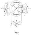
- the first approach illustrated by the figure 1 consists in carrying out mid-point transformers 12, 13 and 14 for attacking, for example, a bridge of field effect transistors 11.
- a bridge of field effect transistors 11 Such a device, passive and reciprocal, advantageously makes it possible to perform both types of functions mentioned above.
- a circuit operating in the microwave is very difficult to achieve in planar technology.
- the second approach is to use an active balun, made from a distributed structure, such as that described in the French patent application filed by the applicant on 21/12/2005 and published under the number 2,895,168 .
- This active balun combines two balanced structures, one of which is composed of "cascade” or “Darlington” type amplifying cells, the other being composed of "cascode” type amplifying cells.
- This particular arrangement makes it possible in particular to solve the problem of imbalance of gain between channels generally existing in conventional assemblies, imbalance between the two output channels (case of a splitter arrangement) or between the two input channels (case of a combiner assembly). It also makes it possible to provide a phase shift of 180 ° between channels.
- a passive balun consisting for example of a structure of the type of that of Marchand's balun.
- a structure known by the way and illustrated by the figure 2 , is based on line couplings, a main line 21 of length equivalent to ⁇ / 2 and two lines 22 and 23 coupled to the main line, lengths ⁇ / 4, and arranged to provide on their respective outputs 25 and 26 signals of the same value in module and in phase opposition. It advantageously makes it possible to perform reciprocal baluns.
- An object of the invention is to propose a solution for producing a balun-type structure that is both reciprocal and broadband (bandwidth greater than one octave).
- the device according to the invention is further characterized in that it also comprises means that can be configured to polarize the different amplification cells so as to induce a determined coupling direction between the first and the second transmission line on the one hand and between the first and the third transmission line on the other hand.
- the means for biasing the amplifying cells are configured, controlled, so that they activate the amplifying cells ensuring the directional coupling in the balun balun element and they deactivate the amplifying cells ensuring the directional coupling in the balun combiner element.
- the means for biasing the amplifying cells are configured, controlled, so that they deactivate the amplifying cells ensuring the directional coupling in the balun balun element and they activate the amplifying cells providing directional coupling in the balun combiner element.
- the device according to the invention has the advantage of constituting a reciprocal active element making it possible to perform on command one or the other of the functions of balun divider or balun combiner.
- the reciprocal nature of the device is in addition to the characteristics of wide bandwidth and wide range of operation of non-reciprocal active baluns known from the prior art.
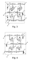
- Figures 3 and 4 schematically show the two active distributed structures at the origin of the device according to the invention.
- the figure 3 has a first structure arranged to constitute a non-active balun reciprocal forming a divider device, while the figure 4 has a second structure arranged to constitute a non-reciprocal active balun forming a combiner device.
- the structure of the figure 3 comprises for this purpose three transmission lines 33, 34 and 35, coupled by means of active cells 31 and 32, amplifiers, shown schematically in the figure, each amplifying cell being formed of transistors (field-effect transistors for example) assembled to form a type of "cascode” (cells 32) or type “Darlington” (cells 31). These two types of assembly are known to present, with respect to each other, a differential phase of about 180 ° in transmission.
- the cells 31 and 32 are further polarized so as to achieve an active and directive coupling between the main line 35 (gate line) and the secondary lines 33 and 34 (drain lines). In this way, a signal present on line 35 is able to propagate by active coupling on lines 33 and 34, the reciprocal being not possible.
- the signal applied on the input 36 of the device thus propagates on the two secondary lines 33 and 34 coupled to the line 35 in the form of two signals in phase opposition, signals which are delivered on the respective outputs 37 and 38 of each of the lines.
- the structure of the figure 4 also comprises for this purpose three transmission lines 43, 44 and 45, coupled by means of active cells 41 and 42, amplifiers, shown schematically in the figure, each cell being formed of transistors (field-effect transistors for example) assembled to form a type of "cascode" (cells 42) or type “Darlington” (cells 41).
- the cells 41 and 42 are further polarized so as to effect an active coupling between the secondary lines 43 and 44 (gate lines) and the main line 45 (drain line). In this way, signals present on the lines 43 and 44 are able to propagate by coupling on the line 45, the reciprocal is not possible.
- the signals applied to the inputs 46 and 47 of the device thus propagate by coupling on the main line 45 and form a combined signal corresponding to the difference of the 2 input signals due to the intrinsic difference of 180 ° between the phases of the assemblies type "cascode” and type “Darlington", which is issued on the exit 48.
- active coupling is thus achieved by means of cells 32, 42, of "cascode” type and of cells 31, 41, of the "Darlington” type distributed between a gate line and a drain line.
- the cell number is furthermore determined, in particular by the desired coupling and gain characteristics.
- the illustrations of Figures 3 and 4 present by way of non-limiting example lines with two cells.
- the propagation lines thus formed are furthermore terminated at their ends which are not used by end loads 39, 49.
- baluns having a wide bandwidth and able to operate for low frequencies, typically from a hundred megahertz.
- the baluns thus formed have the disadvantage of not being reciprocal in their operation, so that according to whether it is desired to divide a signal into two signals or to recombine two signals into a single signal, it is necessary to implement different devices.
- said devices being in the form of integrated circuits, two different types of circuits are used.
- figure 5 presents the schematic diagram of the reciprocal active balun according to the invention.
- the architecture of the reciprocal balun according to the invention is constituted at the base by the association of the architecture of an active balun 30 of the divider type and that of an active balun 40 of the combiner type.
- the combination of these two architectures is first achieved by connecting the outputs 37 and 38 of the propagation lines 33 and 34 of the divider balun 30, to the inputs 46 and 47 of the propagation lines 43 and 44 of the combiner balun 40. is then completed by the connection of the common lines of each of the structures, in other words by the connection of the grid line 35 of the divider balun to the drain line 45 of the combiner balun.
- each link between these lines is The combination of these two architectures is further completed by the suppression of the adaptation loads 39 and 49 implanted at the ends 311 and 411, initially not used, of the main lines 35 and 45 and the lines secondary devices 33, 34 and 43, 44.
- these ends are used to achieve the interconnection of the two common lines 35 and 45, as well as to form two connection points of the ports 52 and 53 allowing the connection of the device to an external circuit. It is finally completed by the deletion of the output 48 of the initial combiner circuit 40 and the implementation of an adaptation load 54.
- a dual structure 50 is thus obtained, comprising a divider element placed in series with a combiner element and having three ports 36, 52 and 53.
- This structure constitutes three propagation lines 55, 56 and 57, the lines 55 and 56 being coupled to line 57 by active cells with transistors.
- this dual structure makes it possible to perform both an active divider balun and an active balun combiner, the ports 36, 52 and 53 alternately playing the role of inputs or outputs.
- the following description explains how the structure according to the invention can be implemented to perform one or the other function.
- balun active and reciprocal the coupling of the line 55 to the line 57 is achieved by active cells of the "Darlington" type, 31 and 41.
- the amplifying cells 31 allow a directional coupling of the line 57 towards the line 55, and the amplifying cells 41 a directional coupling of the line 55 to the line 57.
- the coupling of the line 56 to the line 57 is performed by active cells amplifying "cascode" type, 32 and 42.
- the cells 32 allow a directional coupling of the line 57 to the line 56, and the cells 42 a directional coupling of the line 56 to the line 57. This arrangement of the active cells is not, moreover, the only possible, the device also functioning by permuting the cells 41 and 42.
- the device according to the invention also comprises means, not shown on the figure 5 to ensure, according to the desired operating mode (balun divider or balun combiner), the corresponding polarization of the various active cells 31, 32, 41 and 42.
- any means allowing to polarize either in an active state (or "on") or in an inactive state the different cells performing the active coupling, can here be used.
- This means may for example consist of a control device which, as a function of the value of a control voltage applied to an input of the device according to the invention, polarises the different cells so as to establish a direction of coupling appropriate to the mode. considered.
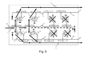
- the figure 6 schematically illustrates the operation of the device according to the invention when it is configured to operate balun divider.
- the amplifying cells 31 and 32 are biased so that they actively couple the line 57 to the lines 55 and 56, while the amplifying cells 41 and 42 are biased so as to be inactive.
- the active cells of the divider element are thus polarized so as to ensure the amplification of the signal between the line 57 (here grid line) input and the two lines of output 55 and 56 (here drain lines). Since the divider element consists of "cascode" cells 32 and "Darlington” cells 31, the signal entering on its gate line via the input port 36 is well divided into two signals of the same amplitude and in phase opposition, available on output ports 52 and 53.
- the active cells of the combiner element are polarized so that the amplification stages which constitute them isolate the lines 55 and 56 of the line 57, thus preventing any recombination at the level of the line 57 of the signals circulating on these lines. lines.
- the figure 7 schematically illustrates the operation of the device according to the invention when it is configured to operate balun combiner.
- cells 41 and 42 are biased so that they actively couple lines 55 and 56 to line 57, while cells 31 and 32 are biased to be inactive.
- signals are applied to inputs 52 and 53 of lines 55 and 56, they are combined by active coupling on line 57; the signal resulting from the combination propagating to the output 36 of the device, as illustrated by the arrows 81.
- the active cells of the combiner element are polarized so as to ensure the amplification of the signal between the 2 lines 55 and 56 (here grid lines) and line 57 (here drain line).
- the combiner element consists of "cascode” amplifier cells 42 and “Darlington” amplifier cells 41, two signals entering on the two gate lines 55 and 56, with identical amplitudes and opposite phases, are summed on line 57. the sum signal being delivered on the output port 36 of the device.
- the active cells, amplifiers, of the divider element are polarized so that the amplification stages which constitute them isolate the line 57 of the lines 55 and 56, thus preventing any propagation of the recombined signal by coupling on the lines 55. and 56.
- the device according to the invention therefore behaves as an active and reciprocal balun.
Landscapes
- Engineering & Computer Science (AREA)
- Power Engineering (AREA)
- Microwave Amplifiers (AREA)
- Amplifiers (AREA)
- Transceivers (AREA)
Abstract
Description
- La présente invention concerne le domaine des dispositifs électroniques connus sous le nom de "baluns", et plus particulièrement le domaine des mélangeurs à large bande passante, employés notamment dans les chaînes d'émission et de réception radioélectriques, et réalisés à partir de baluns.
- Il existe aujourd'hui dans l'industrie des besoins important en termes de mélangeurs large bande. Ces circuits sont utilisés dans certaines chaînes de réception ou d'émission. Par ailleurs, de nombreuses architectures sont envisageables pour réaliser des mélangeurs. Parmi celles-ci on distingue en particulier les structures dites "équilibrées" ou "doublement équilibrées" qui offrent les meilleures performances en termes de réjection de fréquences parasites et de très bons isolements entre voies. II est connu de réaliser un mélangeur doublement équilibré en utilisant un pont de transistors à effet de champ ou un pont de diodes. Par ailleurs pour réaliser un tel circuit en technologie MMIC (Circuit Intégré Monolithique Micro-ondes ou "Monolithic Microwave Intégrated Circuit" selon la terminologie anglo-saxonne), capable de fonctionner sur une large bande de fréquence, il faut disposer d'unités fonctionnelles connues sous le nom de « baluns » large bande.
- Le terme "balun", qui est une contraction de l'expression anglo-saxonne "balanced - unbalanced", désigne de manière générale un dispositif à trois accès capable soit de diviser un signal d'entrée en deux signaux de sortie de même amplitude et déphasés entre eux de 180°, et de réaliser ainsi un circuit diviseur de puissance avec sorties en opposition de phase (balun diviseur), soit de recombiner deux signaux d'entrée de sorte que le signal de sortie représente la différence des signaux d'entrée et de réaliser alors un circuit combineur avec entrées en opposition de phase (balun recombineur).
- Actuellement, il existe deux approches connues pour réaliser un balun.
- La première approche illustrée par la
figure 1 , consiste à réaliser des transformateurs 12, 13 et 14 à point milieu pour attaquer par exemple un pont de transistors à effet de champ 11. Un tel dispositif, passif et réciproque, permet avantageusement de réaliser les deux types de fonctions précitées. Cependant un tel circuit fonctionnant en hyperfréquences est très difficile à réaliser en technologie planaire. De plus, il ne permet pas de travailler sur de très large bande de fréquence (au delà de 2 à 3 octaves) et de descendre bas en fréquence (f < 1 GHz). - La seconde approche consiste à utiliser un balun actif, réalisé à partir d'une structure distribuée, telle que celle décrite dans la demande de brevet français déposée par la demanderesse le 21 /12/ 2005 et publiée sous le numéro
2 895 168 - Cette seconde approche permet de réaliser des baluns fonctionnant à des fréquences basses et sur des bandes de fréquences beaucoup plus larges (de l'ordre de la décade ou plus) que les autres dispositifs existants. Elle constitue donc une solution plus avantageuse que la première approche. Cependant, les structures actives réalisées de cette façon ne sont pas réciproques. Il est donc malheureusement nécessaire de réaliser deux structures différentes pour réaliser un diviseur et un combineur. L'utilisation de ce type de structure dans un mélangeur a pour conséquence de rendre le mélangeur unilatéral.
- Ainsi, quelle que soit l'approche retenue, il n'est pas possible, à l'heure actuelle, de concevoir un balun actif fonctionnant sur une très large bande de fréquence (de la classe de la décade) qui soit réciproque et qui puisse traiter les basses fréquences (f ≤ 1 GHz).
- Par suite si l'on veut réaliser un balun réciproque, on est conduit à l'heure actuelle à utiliser un balun passif constitué par exemple d'une structure du type de celle du balun de Marchand. Une telle structure, connue par ailleurs et illustrée par la
figure 2 , est basée sur des couplages de lignes, une ligne principale 21 de longueur équivalente à λ/2 et deux lignes 22 et 23 couplées à la ligne principale, de longueurs λ/4, et agencées de façon à fournir sur leurs sorties respectives 25 et 26 des signaux de même valeur en module et en opposition de phase. Elle permet avantageusement de réaliser des baluns réciproques. Cependant, l'emploi de coupleurs passifs, introduit des problèmes d'encombrement en particulier lorsque l'on veut travailler à des fréquences relativement basses (autour de 1 GHz), le coupleur passif ayant nécessairement une longueur équivalente à λ/2 à la fréquence centrale de travail du dispositif mélangeur dans lequel il est intégré. Cela rend ce type de structure difficilement intégrable sur des technologies MMIC. De plus, du fait de sa structure, un tel balun ne peut donc être utilisé pour des applications large bande (plusieurs octaves). - Un but de l'invention est de proposer une solution pour réaliser une structure de type balun qui soit à la fois réciproque et large bande (bande passante supérieure à l'octave).
- A cet effet, l'invention a pour objet un balun actif réciproque comportant:
- un élément balun diviseur actif comportant une première ligne de transmission couplée à une deuxième et une troisième ligne de transmission, un premier couplage actif directif de la première ligne de transmission à la deuxième ligne de transmission étant réalisé au moyen de cellules amplificatrices de type "cascode" réparties, connectées aux deux lignes de transmission, un second couplage actif directif de la première ligne de transmission à la troisième ligne de transmission étant réalisé au moyen de cellules amplificatrices de type "Darlington" réparties, connectées entre les deux lignes de transmission;
- un élément balun actif combineur comportant une première et une deuxième ligne de transmission, couplées chacune à une troisième ligne de transmission, un premier couplage actif directif de la première ligne de transmission à la troisième ligne de transmission étant réalisé au moyen de cellules amplificatrices de type "cascode" réparties, connectées aux deux lignes de transmission, un second couplage actif directif de la deuxième ligne de transmission à la troisième ligne de transmission étant réalisé au moyen de cellules amplificatrices de type "Darlington" réparties connectées aux deux lignes de transmission;
- Le dispositif selon l'invention est en outre caractérisé en ce qu'il comporte également des moyens configurables pour polariser les différentes cellules amplificatrices de façons à induire un sens de couplage déterminé entre la première et la deuxième ligne de transmission d'une part et entre la première et la troisième ligne de transmission d'autre part.
- Selon l'invention, dans un mode de fonctionnement où le dispositif exerce la fonction de balun diviseur, les moyens pour polariser les cellules amplificatrices sont configurés, commandés, de façon à ce qu'ils activent les cellules amplificatrices assurant le couplage directif dans l'élément balun diviseur et qu'ils désactivent les cellules amplificatrices assurant le couplage directif dans l'élément balun combineur.
- Selon l'invention, dans un mode de fonctionnement où le dispositif exerce la fonction de balun combineur, les moyens pour polariser les cellules amplificatrices sont configurés, commandés, de façon à ce qu'ils désactivent les cellules amplificatrices assurant le couplage directif dans l'élément balun diviseur et qu'ils activent les cellules amplificatrices assurant le couplage directif dans l'élément balun combineur.
- Le dispositif selon l'invention présente l'avantage de constituer un élément actif réciproque permettant de réaliser sur commande l'une ou l'autre des fonctions de balun diviseur ou de balun combineur.
- Avantageusement le caractère réciproque du dispositif vient s'ajouter aux caractéristiques de large bande passante et de large gamme de fonctionnement des baluns actifs non réciproques connus de l'art antérieur.
- Les caractéristiques et avantages de l'invention seront mieux appréciés grâce à la description qui suit, description qui expose l'invention au travers d'un mode de réalisation particulier pris comme exemple non limitatif et qui s'appuie sur les figures annexées, figures qui représentent:
- la
figure 1 , un schéma présentant la structure d'un mélangeur doublement équilibré réalisé à partir d'un pont de transistors à effet de champ, mélangeur utilise des baluns passifs à base de transformateurs selon l'art antérieur connu; - la
figure 2 , un schéma illustrant la structure du balun de Marchand; - la
figure 3 , un schéma illustrant la structure connue d'un balun actif large bande non réciproque, constitué à partir d'une structure distribuée formant des lignes couplées de manière active, dans une configuration de balun diviseur; - la
figure 4 , un schéma illustrant la structure connue d'un balun actif large bande non réciproque, constitué à partir d'une structure distribuée formant des lignes couplées de manière active, dans une configuration de balun combineur; - la
figure 5 , la structure du balun actif large bande et réciproque selon l'invention; - la
figure 6 , l'illustration de la mise en oeuvre du balun actif réciproque selon l'invention, en mode "balun diviseur"; - la
figure 7 , l'illustration de la mise en oeuvre du balun actif réciproque selon l'invention, en mode "balun combineur"; - On s'intéresse dans un premier temps aux
figures 3 et 4 qui présentent de manière schématique les deux structures distribuées actives à l'origine du dispositif selon l'invention. - Ces deux structures de base sont très largement décrites dans la demande de brevet français déposée par la demanderesse le 21 /12/ 2005 et publiée sous le numéro
2 895 168 figure 3 présente une première structure arrangée pour constituer un balun actif non réciproque formant un dispositif diviseur, tandis que lafigure 4 présente une seconde structure arrangée pour constituer un balun actif non réciproque formant un dispositif combineur. - La structure de la
figure 3 comporte à cet effet trois lignes de transmission 33, 34 et 35, couplées au moyen de cellules actives 31 et 32, amplificatrices, représentées de manière schématique sur la figure, chaque cellule amplificatrice étant formée de transistors (transistors à effet de champ par exemple) assemblés pour former un montage de type "cascode" (cellules 32) ou de type "Darlington" (cellules 31). Ces deux types de montage sont connus pour présenter, l'un par rapport à l'autre, une phase différentielle d'environ 180° en transmission. - Les cellules 31 et 32 sont en outre polarisées de façon à réaliser un couplage actif et directif entre la ligne principale 35 (ligne de grille) et les lignes secondaires 33 et 34 (lignes de drain). De la sorte, un signal présent sur la ligne 35 est en mesure de se propager par couplage actif sur les lignes 33 et 34, la réciproque n'étant pas possible. Le signal appliqué sur l'entrée 36 du dispositif se propage ainsi sur les deux lignes secondaires 33 et 34 couplées à la ligne 35 sous forme de deux signaux en opposition de phase, signaux qui sont délivrés sur les sorties 37 et 38 respectives de chacune des lignes.
- De manière similaire, la structure de la
figure 4 comporte également à cet effet trois lignes de transmission 43, 44 et 45, couplées au moyen de cellules actives 41 et 42, amplificatrices, représentées de manière schématique sur la figure, chaque cellule étant formée de transistors (transistors à effet de champ par exemple) assemblés pour former un montage de type "cascode" (cellules 42) ou de type "Darlington" (cellules 41). Les cellules 41 et 42 sont en outre polarisées de façon à réaliser un couplage actif entre les lignes secondaires 43 et 44 (lignes de grille) et la ligne principale 45 (ligne de drain). De la sorte, des signaux présents sur les lignes 43 et 44 sont en mesure de se propager par couplage sur la ligne 45, la réciproque n'étant pas possible. Les signaux appliqués sur les entrées 46 et 47 du dispositif se propagent ainsi par couplage sur la ligne principale 45 et forment un signal combiné correspondant à la différence des 2 signaux d'entrée du fait de la différence intrinsèque de 180° entre les phases des montages de type "cascode" et de type "Darlington", qui est délivré sur la sortie 48. - Dans ces deux structures, un couplage actif est ainsi réalisé au moyen de cellules 32, 42, de type "cascode" et de cellules 31, 41, de type "Darlington" distribuées entre une ligne de grille et une ligne de drain. Le nombre de cellule est par ailleurs déterminé, en particulier par les caractéristiques de couplage et de gain désirées. Les illustrations des
figures 3 et 4 présentent à titre d'exemple non limitatif des lignes comportant deux cellules. Les lignes de propagation ainsi formées sont en outre terminées à leurs extrémités non utilisées par des charges terminales 39, 49. - Comme il a été dit précédemment, ces deux structures actives permettent avantageusement de réaliser des baluns présentant une large bande passante et pouvant fonctionner pour des fréquences basses, typiquement à partir d'une centaine de mégahertz. En revanche, les baluns ainsi constitués présentent l'inconvénient de pas être réciproques dans leur fonctionnement, de sorte que selon que l'on souhaite réaliser la division d'un signal en deux signaux ou bien la recombinaison de deux signaux en un seul signal, il est nécessaire de mettre en oeuvre des dispositifs différents. Par suite lesdits dispositifs étant réalisés sous forme de circuits intégrés, on est conduit à employer deux types de circuits différents.
- On s'intéresse ensuite à la
figure 5 qui présente le schéma de principe du balun actif réciproque selon l'invention. - Comme l'illustre la
figure 5 , l'architecture du balun réciproque selon l'invention, est constitué à la base par l'association de l'architecture d'un balun actif 30 de type diviseur et de celle d'un balun actif 40 de type combineur. L'association de ces deux architectures est tout d'abord réalisée en reliant les sorties 37 et 38 des lignes de propagation 33 et 34 du balun diviseur 30, aux entrées 46 et 47 des lignes de propagation 43 et 44 du balun combineur 40. Elle est ensuite complétée par la connexion des lignes communes de chacune des structures, autrement dit par la connexion de la ligne de grille 35 du balun diviseur à la ligne de drain 45 du balun combineur. - II est important de noter que pour un bon fonctionnement de la structure, en particulier pour pouvoir commander indépendamment les cellules des baluns diviseur et combineur, chaque liaison entre ces lignes se fait au travers d'un condensateur 51. L'association de ces deux architectures est encore complétée par la suppression des charges d'adaptation 39 et 49 implantées aux extrémités 311 et 411, initialement non utilisées, des lignes principales 35 et 45 et des lignes secondaires 33, 34 et 43, 44. Dans le dispositif selon l'invention ces extrémités sont utilisées pour réaliser l'interconnexion des deux lignes communes 35 et 45, ainsi que pour constituer deux points de connexion des ports 52 et 53 permettant la connexion du dispositif à un circuit extérieur. Elle est enfin complétée par la suppression de la sortie 48 du circuit combineur initial 40 et par la mise en place d'une charge d'adaptation 54.
- On obtient ainsi une structure duale 50, comportant un élément diviseur mis en série avec un élément combineur et comportant trois ports 36, 52 et 53. Cette structure constitue trois lignes de propagation 55, 56 et 57, les lignes 55 et 56 étant couplées à la ligne 57 par des cellules actives à transistors. Avantageusement, cette structure duale permet de réaliser aussi bien un balun actif diviseur qu'un balun actif combineur, les ports 36, 52 et 53 jouant alternativement le rôle d'entrées ou de sorties. La suite de la description explique comment la structure selon l'invention peut être mise en oeuvre pour réaliser l'une ou l'autre fonction.
- Dans le dispositif selon l'invention, balun actif et réciproque, le couplage de la ligne 55 à la ligne 57 est réalisé par des cellules actives de type "Darlington", 31 et 41. Les cellules amplificatrices 31 permettent un couplage directif de la ligne 57 vers la ligne 55, et les cellules amplificatrices 41 un couplage directif de la ligne 55 vers la ligne 57. De même, le couplage de la ligne 56 à la ligne 57 est réalisé par des cellules actives amplificatrices de type "cascode", 32 et 42. Les cellules 32 permettent un couplage directif de la ligne 57 vers la ligne 56, et les cellules 42 un couplage directif de la ligne 56 vers la ligne 57. Cet agencement des cellules actives n'est pas, par ailleurs, le seul possible, le dispositif fonctionnant également en permutant les cellules 41 et 42.
- Pour assurer le fonctionnement de cette architecture duale, le dispositif selon l'invention comporte également des moyens, non représentés sur la
figure 5 , pour assurer, en fonction du mode de fonctionnement désiré (balun diviseur ou balun combineur), la polarisation correspondante des différentes cellules actives 31, 32, 41 et 42. Selon l'invention, tout moyen permettant de polariser soit dans un état actif (ou "passant") soit dans un état inactif les différentes cellules réalisant le couplage actif, peut ici être utilisé. Ce moyen peut par exemple consister en un dispositif de commande qui, en fonction de la valeur d'une tension de commande appliquée sur une entrée du dispositif selon l'invention, polarise les différentes cellules de façon à établir un sens de couplage approprié au mode de fonctionnement considéré. - II est important de rappeler que lorsqu'une ligne (une ligne de grille ou une ligne de drain) ou une portion de ligne est connectée à des cellules polarisées dans l'état "inactif", cette ligne devient purement passive, découplée de toute autre ligne parallèle à elle, et qu'un signal peut se propager le long de cette ligne, dans l'un ou l'autre sens, en subissant peu d'atténuation. Les
figures 6 et7 illustrent la description des deux modes de fonctionnement qui caractérisent l'invention. - La
figure 6 illustre de manière schématique le fonctionnement du dispositif selon l'invention lorsque celui-ci est configuré pour fonctionner en balun diviseur. Dans cette première configuration, les cellules amplificatrices 31 et 32 sont polarisée de façon à ce qu'elles réalisent un couplage actif de la ligne 57 aux lignes 55 et 56, tandis que les cellules amplificatrices 41 et 42 sont polarisées de façon à être inactives. Ainsi comme l'illustre la figure, si l'on applique un signal à l'entrée 36 de la ligne 57, celui-ci se propage par couplage actif sur les lignes 55 et 56 jusqu'au sorties 52 et 53 du dispositif, comme l'illustre les flèches 71. Dans cette première configuration, les cellules actives de l'élément diviseur sont donc polarisées de façon à assurer l'amplification du signal entre la ligne 57 (ici ligne de grille) d'entrée et les deux lignes de sortie 55 et 56 (ici lignes de drain). L'élément diviseur étant constitué de cellules "cascode" 32 et de cellules "Darlington" 31, le signal entrant sur sa ligne de grille par le port d'entrée 36 est bien divisée en deux signaux de même amplitude et en opposition de phase, disponibles sur les ports de sortie 52 et 53. - Inversement, les cellules actives de l'élément combineur sont polarisées de telle sorte que les étages d'amplification qui les constituent isolent les lignes 55 et 56 de la ligne 57, empêchant ainsi toute recombinaison au niveau de la ligne 57 des signaux circulant sur ces lignes.
- La
figure 7 illustre de manière schématique le fonctionnement du dispositif selon l'invention lorsque celui-ci est configuré pour fonctionner en balun combineur. Dans cette première configuration, les cellules 41 et 42 sont polarisées de façon à ce qu'elles réalisent un couplage actif des lignes 55 et 56 à la ligne 57, tandis que les cellules 31 et 32 sont polarisées de façon à être inactives. Ainsi comme l'illustre la figure, si l'on applique des signaux aux entrées 52 et 53 des lignes 55 et 56, ceux-ci se combinent par couplage actif sur la ligne 57; le signal résultant de la combinaison se propageant jusqu'à la sortie 36 du dispositif, comme l'illustre les flèches 81. Dans cette seconde configuration, les cellules actives de l'élément combineur sont donc polarisées de façon à assurer l'amplification du signal entre les 2 lignes 55 et 56 (ici lignes de grille) et la ligne 57 (ici ligne de drain). L'élément combineur étant constitué de cellules amplificatrices "cascode" 42 et de cellules amplificatrices "Darlington" 41, deux signaux entrant sur les 2 lignes de grille 55 et 56, avec des amplitudes identiques et des phases opposées sont sommés sur la ligne 57, le signal somme étant délivré sur le port de sortie 36 du dispositif. - Inversement, les cellules actives, amplificatrices, de l'élément diviseur sont polarisées de telle sorte que les étages d'amplification qui les constituent isolent la ligne 57 des lignes 55 et 56, empêchant ainsi toute propagation du signal recombiné par couplage sur les lignes 55 et 56.
- Le dispositif selon l'invention se comporte donc comme un balun actif et réciproque.
Claims (3)
- Balun actif réciproque comportant:- un élément balun diviseur actif comportant trois lignes (35, 34, 33), formant deux structures amplificatrices distribuées, chaque structure comportant une première ligne de transmission (35) commune avec l'autre structure, la première structure distribuée étant réalisée au moyen de cellules amplificatrices (32) de type "cascode" réparties, connectées à la première ligne de transmission (35) et à une deuxième ligne de transmission (34) de façon à permettre un couplage actif non réciproque du signal de la première ligne (35) à la deuxième ligne (34), la seconde structure distribuée étant réalisée au moyen de cellules amplificatrices (31) de type "Darlington" réparties, connectées entre la première ligne (35) et une troisième ligne de transmission (33), de façon à permettre un couplage actif non réciproque du signal de la première ligne (35) à la troisième ligne (33);- un élément balun actif combineur comportant trois lignes (43, 44, 45), formant deux structures amplificatrices distribuées, chaque structure comportant une première ligne de transmission (45) commune avec l'autre structure, la première structure distribuée étant réalisée au moyen de cellules amplificatrices (42) de type "cascode" réparties, connectées à la première ligne de transmission (45) et à une deuxième ligne de transmission (44) de façon à permettre un couplage actif non réciproque du signal de la deuxième ligne (44) à la première ligne (45), la seconde structure distribuée étant réalisée au moyen de cellules amplificatrices (41) de type "Darlington" réparties, connectées à la première ligne de transmission (45) et à une troisième ligne de transmission (43) de façon à permettre un couplage actif non réciproque du signal de la troisième ligne (43) à la première ligne (45);caractérisé en ce que:- les éléments balun diviseur et balun combineur sont agencés de façon à ce que la ligne commune (35) de l'élément balun diviseur soit connecté à la ligne commune (45) de l'élément balun combineur au travers une capacité (51) afin de constituer une première ligne de transmission unique (57), que la troisième ligne (33) de l'élément balun diviseur soit connecté à la troisième ligne (43) de l'élément balun combineur au travers une capacité (51) afin de constituer une deuxième ligne de transmission unique (55), et que la deuxième ligne (34) de l'élément balun diviseur soit connecté à la deuxième ligne (44) de l'élément balun combineur au travers une capacité (51) afin de constituer une troisième ligne de transmission unique (56);- les impédances de fermeture des lignes de grilles du balun diviseur (39) et du balun combineur (49) sont supprimées afin de réaliser lesdites trois lignes de transmission (55, 56 et 57); le balun actif réciproque comportant des moyens configurables pour polariser les différentes cellules amplificatrices (31, 41, 32 et 42) de façon à induire un sens de couplage déterminé entre la première et la deuxième ligne de transmission d'une part et entre la première et la troisième ligne de transmission d'autre part;un premier couplage actif étant ainsi réalisé entre la première (57) et la deuxième (56) ligne de transmission au moyen de cellules amplificatrices réparties (32, 42) de type "cascode" des éléments baluns diviseur et combineur,et un second couplage actif étant ainsi réalisé entre la première (57) et la troisième (55) ligne de transmission au moyen de cellules amplificatrices réparties (31, 41) de type "Darlington" des éléments baluns diviseur et combineur.
- Dispositif selon la revendication 1 caractérisé en ce que, dans un mode de fonctionnement diviseur, les moyens pour polariser les cellules amplificatrices sont configurés pour activer les cellules amplificatrices (31, 32) assurant le couplage directif dans l'élément balun diviseur et pour désactiver les cellules amplificatrices (41, 42) assurant le couplage directif dans l'élément balun combineur.
- Dispositif selon la revendication 1 caractérisé en ce que, dans un mode de fonctionnement combineur, les moyens pour polariser les cellules amplificatrices sont configurés pour activer les cellules amplificatrices (41, 42) assurant le couplage directif dans l'élément balun combineur et pour désactiver les cellules amplificatrices (31, 32) assurant le couplage directif dans l'élément balun diviseur.
Applications Claiming Priority (1)
| Application Number | Priority Date | Filing Date | Title |
|---|---|---|---|
| FR0707855A FR2923665B1 (fr) | 2007-11-09 | 2007-11-09 | Structure de balun actif reciproque a large bande passante |
Publications (3)
| Publication Number | Publication Date |
|---|---|
| EP2058947A2 true EP2058947A2 (fr) | 2009-05-13 |
| EP2058947A3 EP2058947A3 (fr) | 2013-07-03 |
| EP2058947B1 EP2058947B1 (fr) | 2015-09-23 |
Family
ID=39495993
Family Applications (1)
| Application Number | Title | Priority Date | Filing Date |
|---|---|---|---|
| EP08168497.9A Not-in-force EP2058947B1 (fr) | 2007-11-09 | 2008-11-06 | Structure de balun actif réciproque à large bande passante |
Country Status (3)
| Country | Link |
|---|---|
| US (1) | US7737786B2 (fr) |
| EP (1) | EP2058947B1 (fr) |
| FR (1) | FR2923665B1 (fr) |
Families Citing this family (7)
| Publication number | Priority date | Publication date | Assignee | Title |
|---|---|---|---|---|
| FR2923665B1 (fr) | 2007-11-09 | 2013-04-19 | Thales Sa | Structure de balun actif reciproque a large bande passante |
| US8810314B2 (en) | 2012-02-15 | 2014-08-19 | Auriga Measurement Systems, LLC | Envelope tracking amplifier |
| US10211797B2 (en) * | 2016-07-12 | 2019-02-19 | Teledyne Scientific & Imaging, Llc | Bidirectional amplifier |
| US11522511B2 (en) * | 2020-11-18 | 2022-12-06 | Paulo Carvalho | Digitally controlled multistage combiner with a cascade of combiners |
| US12511410B1 (en) | 2025-03-06 | 2025-12-30 | Qdacomm Llc | Physical layer security |
| US12395128B1 (en) | 2025-03-06 | 2025-08-19 | Qdacomm Llc | Decomposition of signals into a sum of truncated fourier series |
| US12401997B1 (en) | 2025-03-06 | 2025-08-26 | Qdacomm Llc | Physical layer security |
Citations (1)
| Publication number | Priority date | Publication date | Assignee | Title |
|---|---|---|---|---|
| FR2895168A1 (fr) | 2005-12-21 | 2007-06-22 | Thales Sa | Structure de balun a large bande passante. |
Family Cites Families (12)
| Publication number | Priority date | Publication date | Assignee | Title |
|---|---|---|---|---|
| FR2618610B1 (fr) * | 1987-07-20 | 1989-12-22 | Dassault Electronique | Dispositif de retard hyperfrequence |
| US4992752A (en) * | 1989-06-09 | 1991-02-12 | Rockwell International | Method and apparatus for broadband impedance matching |
| FR2727585B1 (fr) * | 1989-11-24 | 1999-08-27 | Dassault Electronique | Amplificateur distribue pour signaux hyperfrequences a large bande |
| US5070304A (en) * | 1990-06-21 | 1991-12-03 | The United States Of America As Represented By The Secretary Of The Air Force | Distributed combiner power amplifier and method |
| US5130664A (en) * | 1991-03-07 | 1992-07-14 | C-Cor Electronics, Inc. | One GHZ CATV repeater station |
| SE517748C2 (sv) * | 2000-11-20 | 2002-07-09 | Totalfoersvarets Forskningsins | Rekonfigurerbar bredbandig aktiv effektdelare, dito effektkombinerare och dito dubbelriktad effektdelare/ effektkombinerare samt kretsar uppbyggda av dessa |
| FR2833779B1 (fr) * | 2001-12-14 | 2004-11-05 | Thales Sa | Dephaseur large bande |
| FR2833782B1 (fr) * | 2001-12-18 | 2004-02-27 | Thales Sa | Commutateur actif large bande a deux entrees et deux sorties a structure distribuee, et dispositif de controle de phase comportant un tel commutateur |
| WO2003065572A1 (fr) * | 2002-01-25 | 2003-08-07 | Centellax, Inc. | Reseau de decalage de niveau reparti pour amplificateurs a large bande en cascade |
| JP4202088B2 (ja) * | 2002-10-24 | 2008-12-24 | 富士通株式会社 | 増幅器 |
| US6727762B1 (en) * | 2002-11-26 | 2004-04-27 | Sirenza Microdevices, Inc. | Direct coupled distributed amplifier |
| FR2923665B1 (fr) | 2007-11-09 | 2013-04-19 | Thales Sa | Structure de balun actif reciproque a large bande passante |
-
2007
- 2007-11-09 FR FR0707855A patent/FR2923665B1/fr not_active Expired - Fee Related
-
2008
- 2008-11-06 EP EP08168497.9A patent/EP2058947B1/fr not_active Not-in-force
- 2008-11-10 US US12/268,374 patent/US7737786B2/en not_active Expired - Fee Related
Patent Citations (1)
| Publication number | Priority date | Publication date | Assignee | Title |
|---|---|---|---|---|
| FR2895168A1 (fr) | 2005-12-21 | 2007-06-22 | Thales Sa | Structure de balun a large bande passante. |
Also Published As
| Publication number | Publication date |
|---|---|
| US20090134951A1 (en) | 2009-05-28 |
| US7737786B2 (en) | 2010-06-15 |
| EP2058947B1 (fr) | 2015-09-23 |
| FR2923665A1 (fr) | 2009-05-15 |
| FR2923665B1 (fr) | 2013-04-19 |
| EP2058947A3 (fr) | 2013-07-03 |
Similar Documents
| Publication | Publication Date | Title |
|---|---|---|
| EP2058947B1 (fr) | Structure de balun actif réciproque à large bande passante | |
| FR2984603A1 (fr) | Circuit integre comprenant un transformateur integre de type "balun" a plusieurs voies d'entree et de sortie. | |
| EP2263311A1 (fr) | Dispositif d'amplification de puissance spatial multi-sources | |
| FR2931300A1 (fr) | Commutateur hyperfrequence et module d'emission et de reception comportant un tel commutateur | |
| FR3062524A1 (fr) | Antenne elementaire a dispositif rayonnant planaire | |
| EP3462532B1 (fr) | Répartiteur de puissance pour antenne comportant quatre transducteurs orthomodes identiques | |
| EP2159922B1 (fr) | Duplexeur actif hyperfréquence commandé | |
| WO2019243493A1 (fr) | Excitateur radiofrequence d'antenne en reception et transmission | |
| EP0472483A1 (fr) | Duplexeur bidirectionnel pour ondes hyperfréquences polarisées réalisable notamment en technologie monolithique sur arséniure de gallium | |
| FR2595173A1 (fr) | Circuit amplificateur distribue large bande dans le domaine des hyperfrequences | |
| EP1148631A1 (fr) | Convertisseur de fréquence avec rejet de fréquence image | |
| EP1183777B1 (fr) | Filtre passe-bande a reduction de la frequence porteuse | |
| FR2871951A1 (fr) | Dispositif de transition rntre un guide d'ondes et deux circuits redondants chacun couple a une ligne coplanaire | |
| EP0943176A1 (fr) | Melangeur compact doublement equilibre a quad de tecs froids en technologie mmic | |
| CA2348803A1 (fr) | Melangeur doublement equilibre en technologie mmic | |
| EP2457326A1 (fr) | Structure hyperfréquences de commutation à amplificateur distribué avec entrée d'injection de signal de test | |
| FR2460049A1 (fr) | Filtre coupe-bande pour ligne de transmission hyperfrequence et circuit de polarisation de transistor hyperfrequence comprenant ce filtre | |
| EP1801968B1 (fr) | Structure de balun à large bande passante | |
| FR2658964A1 (fr) | Liaison de puissance, protegee par redondance, pour signaux hyperfrequence. | |
| EP2168242B1 (fr) | Dispositif de commutation actif et circuit intégré hyperfrequences comportant un tel dispositif | |
| EP1017171A1 (fr) | Dispositif de contrôle de phase constitué de multiples structures amplificatrices distribuées à éléments actifs commutables pour former une ligne à longueur programmable | |
| FR3159053A1 (fr) | Antenne élémentaire multi-ports améliorée et antenne réseau à balayage électronique actif associée | |
| FR2929796A1 (fr) | Coupleur pour systeme radio frequences multibandes. | |
| EP2936682A1 (fr) | Dispositif de commutation de signaux hyperfrequences notamment de dimensions nanometriques, et composant electronique incorporant un tel dispositif | |
| US7292121B1 (en) | RF combining device and method |
Legal Events
| Date | Code | Title | Description |
|---|---|---|---|
| PUAI | Public reference made under article 153(3) epc to a published international application that has entered the european phase |
Free format text: ORIGINAL CODE: 0009012 |
|
| AK | Designated contracting states |
Kind code of ref document: A2 Designated state(s): AT BE BG CH CY CZ DE DK EE ES FI FR GB GR HR HU IE IS IT LI LT LU LV MC MT NL NO PL PT RO SE SI SK TR |
|
| AX | Request for extension of the european patent |
Extension state: AL BA MK RS |
|
| PUAL | Search report despatched |
Free format text: ORIGINAL CODE: 0009013 |
|
| AK | Designated contracting states |
Kind code of ref document: A3 Designated state(s): AT BE BG CH CY CZ DE DK EE ES FI FR GB GR HR HU IE IS IT LI LT LU LV MC MT NL NO PL PT RO SE SI SK TR |
|
| AX | Request for extension of the european patent |
Extension state: AL BA MK RS |
|
| RIC1 | Information provided on ipc code assigned before grant |
Ipc: H03F 1/22 20060101ALI20130527BHEP Ipc: H03F 3/21 20060101ALI20130527BHEP Ipc: H03H 11/32 20060101AFI20130527BHEP Ipc: H03F 3/62 20060101ALI20130527BHEP Ipc: H03F 3/60 20060101ALI20130527BHEP |
|
| 17P | Request for examination filed |
Effective date: 20131227 |
|
| RBV | Designated contracting states (corrected) |
Designated state(s): AT BE BG CH CY CZ DE DK EE ES FI FR GB GR HR HU IE IS IT LI LT LU LV MC MT NL NO PL PT RO SE SI SK TR |
|
| RBV | Designated contracting states (corrected) |
Designated state(s): AT BE BG CH CY CZ DE DK EE ES FI FR GB GR HR HU IE IS IT LI LT LU LV MC MT NL NO PL PT RO SE SI SK TR |
|
| 17Q | First examination report despatched |
Effective date: 20140203 |
|
| RBV | Designated contracting states (corrected) |
Designated state(s): AT BE BG CH CY CZ DE DK EE ES FI FR GB GR HR HU IE IS IT LI LT LU LV MC MT NL NO PL PT RO SE SI SK TR |
|
| AKX | Designation fees paid |
Designated state(s): AT BE BG CH CY CZ DE DK EE ES FI FR GB GR HR HU IE IS IT LI LT LU LV MC MT NL NO PL PT RO SE SI SK TR |
|
| REG | Reference to a national code |
Ref country code: DE Ref legal event code: R079 Ref document number: 602008040285 Country of ref document: DE Free format text: PREVIOUS MAIN CLASS: H03H0011320000 Ipc: H03D0007140000 |
|
| GRAP | Despatch of communication of intention to grant a patent |
Free format text: ORIGINAL CODE: EPIDOSNIGR1 |
|
| RIC1 | Information provided on ipc code assigned before grant |
Ipc: H03H 11/32 20060101ALI20150325BHEP Ipc: H03F 3/21 20060101ALI20150325BHEP Ipc: H03D 7/14 20060101AFI20150325BHEP Ipc: H03F 1/22 20060101ALI20150325BHEP Ipc: H03F 3/60 20060101ALI20150325BHEP Ipc: H03F 3/62 20060101ALI20150325BHEP |
|
| RIN1 | Information on inventor provided before grant (corrected) |
Inventor name: DUEME, PHILIPPE Inventor name: PLAZE, JEAN-MICHEL Inventor name: MALLET-GUY, BENOIT |
|
| INTG | Intention to grant announced |
Effective date: 20150417 |
|
| GRAS | Grant fee paid |
Free format text: ORIGINAL CODE: EPIDOSNIGR3 |
|
| GRAA | (expected) grant |
Free format text: ORIGINAL CODE: 0009210 |
|
| AK | Designated contracting states |
Kind code of ref document: B1 Designated state(s): AT BE BG CH CY CZ DE DK EE ES FI FR GB GR HR HU IE IS IT LI LT LU LV MC MT NL NO PL PT RO SE SI SK TR |
|
| REG | Reference to a national code |
Ref country code: GB Ref legal event code: FG4D Free format text: NOT ENGLISH |
|
| REG | Reference to a national code |
Ref country code: CH Ref legal event code: EP |
|
| REG | Reference to a national code |
Ref country code: AT Ref legal event code: REF Ref document number: 751698 Country of ref document: AT Kind code of ref document: T Effective date: 20151015 |
|
| REG | Reference to a national code |
Ref country code: IE Ref legal event code: FG4D Free format text: LANGUAGE OF EP DOCUMENT: FRENCH |
|
| REG | Reference to a national code |
Ref country code: FR Ref legal event code: PLFP Year of fee payment: 8 |
|
| REG | Reference to a national code |
Ref country code: DE Ref legal event code: R096 Ref document number: 602008040285 Country of ref document: DE |
|
| REG | Reference to a national code |
Ref country code: NL Ref legal event code: MP Effective date: 20150923 |
|
| PG25 | Lapsed in a contracting state [announced via postgrant information from national office to epo] |
Ref country code: NO Free format text: LAPSE BECAUSE OF FAILURE TO SUBMIT A TRANSLATION OF THE DESCRIPTION OR TO PAY THE FEE WITHIN THE PRESCRIBED TIME-LIMIT Effective date: 20151223 Ref country code: LT Free format text: LAPSE BECAUSE OF FAILURE TO SUBMIT A TRANSLATION OF THE DESCRIPTION OR TO PAY THE FEE WITHIN THE PRESCRIBED TIME-LIMIT Effective date: 20150923 Ref country code: GR Free format text: LAPSE BECAUSE OF FAILURE TO SUBMIT A TRANSLATION OF THE DESCRIPTION OR TO PAY THE FEE WITHIN THE PRESCRIBED TIME-LIMIT Effective date: 20151224 Ref country code: FI Free format text: LAPSE BECAUSE OF FAILURE TO SUBMIT A TRANSLATION OF THE DESCRIPTION OR TO PAY THE FEE WITHIN THE PRESCRIBED TIME-LIMIT Effective date: 20150923 Ref country code: LV Free format text: LAPSE BECAUSE OF FAILURE TO SUBMIT A TRANSLATION OF THE DESCRIPTION OR TO PAY THE FEE WITHIN THE PRESCRIBED TIME-LIMIT Effective date: 20150923 |
|
| REG | Reference to a national code |
Ref country code: LT Ref legal event code: MG4D |
|
| REG | Reference to a national code |
Ref country code: AT Ref legal event code: MK05 Ref document number: 751698 Country of ref document: AT Kind code of ref document: T Effective date: 20150923 |
|
| PG25 | Lapsed in a contracting state [announced via postgrant information from national office to epo] |
Ref country code: SE Free format text: LAPSE BECAUSE OF FAILURE TO SUBMIT A TRANSLATION OF THE DESCRIPTION OR TO PAY THE FEE WITHIN THE PRESCRIBED TIME-LIMIT Effective date: 20150923 Ref country code: HR Free format text: LAPSE BECAUSE OF FAILURE TO SUBMIT A TRANSLATION OF THE DESCRIPTION OR TO PAY THE FEE WITHIN THE PRESCRIBED TIME-LIMIT Effective date: 20150923 |
|
| PG25 | Lapsed in a contracting state [announced via postgrant information from national office to epo] |
Ref country code: NL Free format text: LAPSE BECAUSE OF FAILURE TO SUBMIT A TRANSLATION OF THE DESCRIPTION OR TO PAY THE FEE WITHIN THE PRESCRIBED TIME-LIMIT Effective date: 20150923 |
|
| PG25 | Lapsed in a contracting state [announced via postgrant information from national office to epo] |
Ref country code: IS Free format text: LAPSE BECAUSE OF FAILURE TO SUBMIT A TRANSLATION OF THE DESCRIPTION OR TO PAY THE FEE WITHIN THE PRESCRIBED TIME-LIMIT Effective date: 20160123 Ref country code: EE Free format text: LAPSE BECAUSE OF FAILURE TO SUBMIT A TRANSLATION OF THE DESCRIPTION OR TO PAY THE FEE WITHIN THE PRESCRIBED TIME-LIMIT Effective date: 20150923 Ref country code: SK Free format text: LAPSE BECAUSE OF FAILURE TO SUBMIT A TRANSLATION OF THE DESCRIPTION OR TO PAY THE FEE WITHIN THE PRESCRIBED TIME-LIMIT Effective date: 20150923 Ref country code: ES Free format text: LAPSE BECAUSE OF FAILURE TO SUBMIT A TRANSLATION OF THE DESCRIPTION OR TO PAY THE FEE WITHIN THE PRESCRIBED TIME-LIMIT Effective date: 20150923 Ref country code: CZ Free format text: LAPSE BECAUSE OF FAILURE TO SUBMIT A TRANSLATION OF THE DESCRIPTION OR TO PAY THE FEE WITHIN THE PRESCRIBED TIME-LIMIT Effective date: 20150923 |
|
| PG25 | Lapsed in a contracting state [announced via postgrant information from national office to epo] |
Ref country code: PT Free format text: LAPSE BECAUSE OF FAILURE TO SUBMIT A TRANSLATION OF THE DESCRIPTION OR TO PAY THE FEE WITHIN THE PRESCRIBED TIME-LIMIT Effective date: 20160125 Ref country code: AT Free format text: LAPSE BECAUSE OF FAILURE TO SUBMIT A TRANSLATION OF THE DESCRIPTION OR TO PAY THE FEE WITHIN THE PRESCRIBED TIME-LIMIT Effective date: 20150923 Ref country code: PL Free format text: LAPSE BECAUSE OF FAILURE TO SUBMIT A TRANSLATION OF THE DESCRIPTION OR TO PAY THE FEE WITHIN THE PRESCRIBED TIME-LIMIT Effective date: 20150923 Ref country code: RO Free format text: LAPSE BECAUSE OF FAILURE TO SUBMIT A TRANSLATION OF THE DESCRIPTION OR TO PAY THE FEE WITHIN THE PRESCRIBED TIME-LIMIT Effective date: 20150923 |
|
| REG | Reference to a national code |
Ref country code: DE Ref legal event code: R097 Ref document number: 602008040285 Country of ref document: DE |
|
| PG25 | Lapsed in a contracting state [announced via postgrant information from national office to epo] |
Ref country code: MC Free format text: LAPSE BECAUSE OF FAILURE TO SUBMIT A TRANSLATION OF THE DESCRIPTION OR TO PAY THE FEE WITHIN THE PRESCRIBED TIME-LIMIT Effective date: 20150923 Ref country code: LU Free format text: LAPSE BECAUSE OF FAILURE TO SUBMIT A TRANSLATION OF THE DESCRIPTION OR TO PAY THE FEE WITHIN THE PRESCRIBED TIME-LIMIT Effective date: 20151106 |
|
| REG | Reference to a national code |
Ref country code: CH Ref legal event code: PL |
|
| PG25 | Lapsed in a contracting state [announced via postgrant information from national office to epo] |
Ref country code: CH Free format text: LAPSE BECAUSE OF NON-PAYMENT OF DUE FEES Effective date: 20151130 Ref country code: LI Free format text: LAPSE BECAUSE OF NON-PAYMENT OF DUE FEES Effective date: 20151130 |
|
| PLBE | No opposition filed within time limit |
Free format text: ORIGINAL CODE: 0009261 |
|
| STAA | Information on the status of an ep patent application or granted ep patent |
Free format text: STATUS: NO OPPOSITION FILED WITHIN TIME LIMIT |
|
| REG | Reference to a national code |
Ref country code: IE Ref legal event code: MM4A |
|
| 26N | No opposition filed |
Effective date: 20160624 |
|
| PG25 | Lapsed in a contracting state [announced via postgrant information from national office to epo] |
Ref country code: DK Free format text: LAPSE BECAUSE OF FAILURE TO SUBMIT A TRANSLATION OF THE DESCRIPTION OR TO PAY THE FEE WITHIN THE PRESCRIBED TIME-LIMIT Effective date: 20150923 |
|
| REG | Reference to a national code |
Ref country code: FR Ref legal event code: PLFP Year of fee payment: 9 |
|
| PG25 | Lapsed in a contracting state [announced via postgrant information from national office to epo] |
Ref country code: IE Free format text: LAPSE BECAUSE OF NON-PAYMENT OF DUE FEES Effective date: 20151106 |
|
| PG25 | Lapsed in a contracting state [announced via postgrant information from national office to epo] |
Ref country code: SI Free format text: LAPSE BECAUSE OF FAILURE TO SUBMIT A TRANSLATION OF THE DESCRIPTION OR TO PAY THE FEE WITHIN THE PRESCRIBED TIME-LIMIT Effective date: 20150923 |
|
| PG25 | Lapsed in a contracting state [announced via postgrant information from national office to epo] |
Ref country code: HU Free format text: LAPSE BECAUSE OF FAILURE TO SUBMIT A TRANSLATION OF THE DESCRIPTION OR TO PAY THE FEE WITHIN THE PRESCRIBED TIME-LIMIT; INVALID AB INITIO Effective date: 20081106 Ref country code: BG Free format text: LAPSE BECAUSE OF FAILURE TO SUBMIT A TRANSLATION OF THE DESCRIPTION OR TO PAY THE FEE WITHIN THE PRESCRIBED TIME-LIMIT Effective date: 20150923 |
|
| PG25 | Lapsed in a contracting state [announced via postgrant information from national office to epo] |
Ref country code: CY Free format text: LAPSE BECAUSE OF FAILURE TO SUBMIT A TRANSLATION OF THE DESCRIPTION OR TO PAY THE FEE WITHIN THE PRESCRIBED TIME-LIMIT Effective date: 20150923 |
|
| PG25 | Lapsed in a contracting state [announced via postgrant information from national office to epo] |
Ref country code: BE Free format text: LAPSE BECAUSE OF NON-PAYMENT OF DUE FEES Effective date: 20151130 |
|
| PG25 | Lapsed in a contracting state [announced via postgrant information from national office to epo] |
Ref country code: TR Free format text: LAPSE BECAUSE OF FAILURE TO SUBMIT A TRANSLATION OF THE DESCRIPTION OR TO PAY THE FEE WITHIN THE PRESCRIBED TIME-LIMIT Effective date: 20150923 Ref country code: MT Free format text: LAPSE BECAUSE OF FAILURE TO SUBMIT A TRANSLATION OF THE DESCRIPTION OR TO PAY THE FEE WITHIN THE PRESCRIBED TIME-LIMIT Effective date: 20150923 |
|
| REG | Reference to a national code |
Ref country code: FR Ref legal event code: PLFP Year of fee payment: 10 |
|
| REG | Reference to a national code |
Ref country code: FR Ref legal event code: PLFP Year of fee payment: 11 |
|
| PGFP | Annual fee paid to national office [announced via postgrant information from national office to epo] |
Ref country code: GB Payment date: 20201028 Year of fee payment: 13 Ref country code: IT Payment date: 20201027 Year of fee payment: 13 Ref country code: DE Payment date: 20201028 Year of fee payment: 13 |
|
| PGFP | Annual fee paid to national office [announced via postgrant information from national office to epo] |
Ref country code: FR Payment date: 20211108 Year of fee payment: 14 |
|
| REG | Reference to a national code |
Ref country code: DE Ref legal event code: R119 Ref document number: 602008040285 Country of ref document: DE |
|
| GBPC | Gb: european patent ceased through non-payment of renewal fee |
Effective date: 20211106 |
|
| PG25 | Lapsed in a contracting state [announced via postgrant information from national office to epo] |
Ref country code: GB Free format text: LAPSE BECAUSE OF NON-PAYMENT OF DUE FEES Effective date: 20211106 Ref country code: DE Free format text: LAPSE BECAUSE OF NON-PAYMENT OF DUE FEES Effective date: 20220601 |
|
| PG25 | Lapsed in a contracting state [announced via postgrant information from national office to epo] |
Ref country code: IT Free format text: LAPSE BECAUSE OF NON-PAYMENT OF DUE FEES Effective date: 20211106 |
|
| P01 | Opt-out of the competence of the unified patent court (upc) registered |
Effective date: 20230427 |
|
| PG25 | Lapsed in a contracting state [announced via postgrant information from national office to epo] |
Ref country code: FR Free format text: LAPSE BECAUSE OF NON-PAYMENT OF DUE FEES Effective date: 20221130 |