EP2058901A1 - Antenne à piège réfléchissant - Google Patents
Antenne à piège réfléchissant Download PDFInfo
- Publication number
- EP2058901A1 EP2058901A1 EP08168505A EP08168505A EP2058901A1 EP 2058901 A1 EP2058901 A1 EP 2058901A1 EP 08168505 A EP08168505 A EP 08168505A EP 08168505 A EP08168505 A EP 08168505A EP 2058901 A1 EP2058901 A1 EP 2058901A1
- Authority
- EP
- European Patent Office
- Prior art keywords
- antenna
- reflecting means
- radiating elements
- reflecting
- reflector
- Prior art date
- Legal status (The legal status is an assumption and is not a legal conclusion. Google has not performed a legal analysis and makes no representation as to the accuracy of the status listed.)
- Granted
Links
- 229910052782 aluminium Inorganic materials 0.000 claims abstract description 4
- XAGFODPZIPBFFR-UHFFFAOYSA-N aluminium Chemical compound [Al] XAGFODPZIPBFFR-UHFFFAOYSA-N 0.000 claims abstract description 4
- 230000008878 coupling Effects 0.000 claims description 5
- 238000010168 coupling process Methods 0.000 claims description 5
- 238000005859 coupling reaction Methods 0.000 claims description 5
- 229910052751 metal Inorganic materials 0.000 claims description 5
- 239000002184 metal Substances 0.000 claims description 5
- 239000003989 dielectric material Substances 0.000 claims description 4
- 239000011888 foil Substances 0.000 claims description 2
- 238000005388 cross polarization Methods 0.000 description 6
- 230000009977 dual effect Effects 0.000 description 2
- 238000009413 insulation Methods 0.000 description 2
- 230000005855 radiation Effects 0.000 description 2
- 230000010267 cellular communication Effects 0.000 description 1
- 239000004020 conductor Substances 0.000 description 1
- 230000000694 effects Effects 0.000 description 1
- 230000010287 polarization Effects 0.000 description 1
- 230000006641 stabilisation Effects 0.000 description 1
- 238000011105 stabilization Methods 0.000 description 1
Images


Classifications
-
- H—ELECTRICITY
- H01—ELECTRIC ELEMENTS
- H01Q—ANTENNAS, i.e. RADIO AERIALS
- H01Q1/00—Details of, or arrangements associated with, antennas
- H01Q1/12—Supports; Mounting means
- H01Q1/22—Supports; Mounting means by structural association with other equipment or articles
- H01Q1/24—Supports; Mounting means by structural association with other equipment or articles with receiving set
- H01Q1/241—Supports; Mounting means by structural association with other equipment or articles with receiving set used in mobile communications, e.g. GSM
- H01Q1/246—Supports; Mounting means by structural association with other equipment or articles with receiving set used in mobile communications, e.g. GSM specially adapted for base stations
-
- H—ELECTRICITY
- H01—ELECTRIC ELEMENTS
- H01Q—ANTENNAS, i.e. RADIO AERIALS
- H01Q19/00—Combinations of primary active antenna elements and units with secondary devices, e.g. with quasi-optical devices, for giving the antenna a desired directional characteristic
- H01Q19/10—Combinations of primary active antenna elements and units with secondary devices, e.g. with quasi-optical devices, for giving the antenna a desired directional characteristic using reflecting surfaces
- H01Q19/106—Combinations of primary active antenna elements and units with secondary devices, e.g. with quasi-optical devices, for giving the antenna a desired directional characteristic using reflecting surfaces using two or more intersecting plane surfaces, e.g. corner reflector antennas
-
- H—ELECTRICITY
- H01—ELECTRIC ELEMENTS
- H01Q—ANTENNAS, i.e. RADIO AERIALS
- H01Q21/00—Antenna arrays or systems
- H01Q21/06—Arrays of individually energised antenna units similarly polarised and spaced apart
- H01Q21/08—Arrays of individually energised antenna units similarly polarised and spaced apart the units being spaced along or adjacent to a rectilinear path
Definitions
- the present invention relates to a telecommunication antenna, used in particular for the base stations of the cellular communication networks (GSM, UMTS).
- GSM Global System for Mobile communications
- UMTS cellular communication networks
- Such an antenna is formed of networks of radiating elements slightly spaced.
- the invention relates in particular to the reflecting means which is provided with this antenna.
- a telecommunications antenna transmits and receives radio waves at frequencies specific to a telecommunications system operated by this antenna.
- an antenna for the UMTS system uses frequency waves in the band 1710 to 2170 MHz.
- a base station has an antenna array and feeds each antenna with frequency waves included in the band operated by it.
- the distance between the antennas is short, which has the consequence that each antenna has an influence on the adjacent antenna.
- the document US 5710569 There is the problem of minimizing the lateral radiation of an antenna, a source of interference with neighboring antennas, modifying the width of the horizontal beam and improving the front-to-back ratio.
- This document describes an antenna comprising aligned dipoles fixed on the flat base of a reflector with edges folded upwards. Choke reflectors are arranged in the space between the dipole and the lateral fold of the reflector, of which they are distinct, so as to form a screen on either side of the row of dipoles. These traps are composed of metal sheets folded in L and fixed on the flat base of the reflector supporting the dipoles. They can be moved in a horizontal direction so as to move closer to or away from the dipole alignment, in order to modify the characteristics of the antenna.
- the document EP-0 973 231 The aim is to minimize the side lobes of an antenna, a source of interference with adjacent antennas, and to obtain the characteristics of a bi-polarization with a single antenna. This document also mentions the possibility of controlling the insulation by adjusting the position of the traps.
- This document describes an antenna comprising radiating elements fixed on the flat part of a reflector having folded edges downwards. Two longitudinally movable "choke reflectors" are arranged along the elements radiating on the flat part of the reflector. Transverse traps are further placed between the radiating elements perpendicular to the lateral traps.
- trap is given to simple angles forming two parallel flat surfaces flanking closer aligned radiating elements. These traps have the function of modifying the opening value of the antenna.
- the authors of these documents seek a control of the nominal value of the opening of the antenna by arranging the traps in the central zone of the antenna, closer to the dipoles.
- the present invention aims to improve the stability of the beamwidth in the horizontal plane of a radiofrequency antenna. Another object of the invention is to improve the performance of this cross-polarized antenna in the main axis and at an angle of ⁇ 60 ° to the axis of the antenna.
- the object of the present invention is an antenna comprising an array of aligned radiating elements, a first reflecting means comprising a flat central part on which the radiating elements are arranged and edges folded longitudinally on either side of the alignment. elements, and at least a second reflecting means.
- the second reflecting means is a reflecting trap disposed outside the space separating the radiating elements from the folded edge of the first reflecting means, and it is separated from the first reflecting means by a layer of dielectric material so as to be connected by capacitive coupling to the first reflecting means.
- the second reflecting means according to the invention is disposed outside the folded edges of the first reflecting means of the antenna, outside the immediate zone of radiation of the elements, which consequently produces the stabilization of the opening value. of the antenna and simultaneously improves the cross-polarization parameters.
- the second reflecting means according to the invention is connected to the first reflecting means by indirect electrical coupling or capacitive coupling. This represents an improvement of the prior art: simple assembly and absence of intermodulation constraints resulting from a bad assembly between parts.
- the second reflecting means is separated from the first reflecting means by a layer of dielectric material. Thus the parts connected to the earth are not in direct contact.
- the reflecting trap according to the invention does not act on the nominal value of the opening of the antenna, but has the effect of improving the stability of this value.
- the invention makes it possible to improve the cross polarization parameters of the antenna, whereas the prior art only describes vertically polarized antennas.
- the value of the insulation is not influenced by the presence of traps because they are placed too far away from the radiating elements.
- the second reflecting means is a U-shaped folded metal sheet, the outer face of one of the branches of the U cooperating with the outer face of a folded edge of the first means. reflective.
- the branches of the U are of unequal lengths.
- the metal sheet is aluminum.
- the second reflecting means is disposed on at least a part of the total length of the antenna.
- the trap is applied against the outer face of the folded edges of the first reflecting means, on certain portions of the length of the first reflecting means.
- the reflective trap may also cover the entire length of the first reflective means.
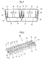
- the antenna 1 comprises elements 2, such as dipoles, radiating a radiofrequency signal, aligned along a longitudinal main axis X-X '.
- the antenna 1 also comprises a reflecting means 3, connected to the ground, composed of a flat part 4 and side edges 5 folded upwards, parallel to the axis XX 'on each side of the row of radiating elements 2.
- the radiating elements 2 are fixed on the flat part 4 of the reflector 3.
- the transverse walls 6 separate the radiating elements 2, and rest on the lateral edges 5 of the reflector 3.
- the radiating elements 2 are powered electrically by lines 7 connected to connectors 8 carried by the transverse end walls 9.
- the antenna 1 further comprises a supply network of the radiating elements 2 (not shown).
- the antenna 1 comprises reflective traps 10 formed of a U-shaped folded aluminum foil placed longitudinally outside the reflector 3, outside the zone of proximity of the radiating elements 2.
- the outer face 11 of one of the branches of the U is contiguous to the outer face 12 of the lateral edge 5 of the reflector 3, as shown in FIGS. Figures 2a and 2b .
- the U branch of the trap 10 is separated by a layer 13 of a dielectric material from the lateral edge 5 of the reflector 3 to which it is contiguous.
- the capacitive coupling equivalent to a short-circuit for radio frequencies, which is made between the lower portion 14 of the reflecting trap 10 and the lower angle 15 of the reflector 3 leads to an open circuit at the upper edge 16 of the reflector. 3.
- the line 19, of an unwound length of the order of a half-wavelength is a quarter-wave transformer formed by the two opposite conductors, respectively the inside of the trap 10 and the outside of the reflector 3.
- the other U-leg of the trap 10, which is not contiguous to the reflector 3 has a length 20 on the order of a quarter of the wavelength in this case.
- the radiating elements 2 are further protected by a housing 21.
- each row has a reflector 31, formed of a flat base 32, 32 ' provided with folded lateral edges 33, 33' flanking each row of radiating elements 30. Traps 34, 34 ' are contiguous to the outer face 35, 35 ' edges 33, 33' of each of the reflectors 31, 31 '. Thus each row of radiating elements 30 has its own reflector 31, 31 'framed by two traps 34, 34'. The two rows of radiating elements 30 are further protected by a common housing 36 .
- an antenna 40 having two rows of radiating elements 41 fixed on the flat portion 42, 42 ' of their respective reflectors 43, 43' comprising longitudinal edges 44, 44 ' folded. Traps 45, 45 ' are arranged on the outer side of the folded edges 44, 44' , on only a part of the length of the antenna 40.
- a dual polarized antenna has two + 45 ° and -45 ° identified ports that correspond to the two antenna connectors.
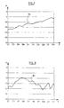
- the figure 5 shows the variation of the aperture W at -3 dB of the beam of an antenna of the prior art for one of the two ports at -45 ° (curve 50 ).
- the figure 6 shows the variation of the aperture W at -3 dB of the beam of an antenna comprising two traps according to one embodiment of the invention for one of the two ports at -45 ° (curve 60 ) .
- the figure 7 shows the evolution of the cross polarization P of an antenna of the prior art in the sector at +/- 60 ° of the main axis of the antenna for one of the two ports at -45 ° (curve 70 ).
- the figure 8 shows the evolution of the crossed polarization P of an antenna comprising two traps according to one embodiment of the invention in the sector at +/- 60 ° of the main axis of the antenna for one of the two ports at -45 ° (curve 80 ).
Landscapes
- Engineering & Computer Science (AREA)
- Computer Networks & Wireless Communication (AREA)
- Aerials With Secondary Devices (AREA)
- Variable-Direction Aerials And Aerial Arrays (AREA)
- Organic Low-Molecular-Weight Compounds And Preparation Thereof (AREA)
- Glass Compositions (AREA)
- Support Of Aerials (AREA)
Abstract
Description
- La présente invention se rapporte à une antenne de télécommunication, utilisée notamment pour les stations de base des réseaux de communication cellulaires (GSM, UMTS). Une telle antenne est formée de réseaux d'éléments rayonnants faiblement espacés. L'invention concerne en particulier les moyens réfléchissants dont est munie cette antenne.
- Une antenne de télécommunications émet et reçoit des ondes radioélectriques suivant des fréquences propres à un système de télécommunications exploité par cette antenne. Ainsi, une antenne destinée au système UMTS utilise des ondes de fréquences comprises dans la bande 1710 à 2170 MHz. Une station de base comporte un réseau d'antenne et alimente chaque antenne avec des ondes de fréquences comprises dans la bande exploitée par celle-ci. Cependant la distance entre les antennes est courte ce qui a pour conséquence que chaque antenne a une influence sur l'antenne adjacente.
- Le document
US-5,710,569 se pose le problème de minimiser le rayonnement latérale d'une antenne, source d'interférence avec les antennes voisines, de modifier la largeur du faisceau horizontal et d'améliorer le rapport avant/arrière ("front-to-back ratio"). Ce document décrit une antenne comprenant des dipôles alignés fixés sur la base plane d'un réflecteur à bords repliés vers le haut. Des pièges ("choke reflectors") sont disposés dans l'espace compris entre le dipôle et le repli latéral du réflecteur, dont ils sont distincts, de manière à former écran de part et d'autre de la rangée de dipôles. Ces pièges sont composés des feuilles métalliques pliées en L et fixés sur la base plane du réflecteur supportant les dipôles. Ils peuvent être déplacés dans une direction horizontale de manière à se rapprocher ou s'éloigner de l'alignement de dipôles, afin de modifier les caractéristiques de l'antenne. - Le document
EP-0 973 231 se donne comme but de minimiser les lobes latéraux d'une antenne, source d'interférence avec les antennes adjacentes, et d'obtenir les caractéristiques d'une bi-polarisation avec une seule antenne. Ce document mentionne également la possibilité de contrôler l'isolation en ajustant la position des pièges. Ce document décrit une antenne comprenant des éléments rayonnants fixés sur la partie plate d'un réflecteur comportant des bords repliés vers le bas. Deux pièges ("choke reflectors") mobiles longitudinalement, sont disposés le long des éléments rayonnants sur la partie plane du réflecteur. Des pièges transversaux sont en outre placés entre les éléments rayonnants perpendiculairement aux pièges latéraux. - Dans ces documents, l'appellation "piège" est donnée à de simples cornières formant deux surfaces planes parallèles encadrant au plus près les éléments rayonnants alignés. Ces pièges ont pour fonction de modifier la valeur d'ouverture de l'antenne. Les auteurs de ces documents recherchent un contrôle de la valeur nominale de l'ouverture de l'antenne en disposant les pièges dans la zone centrale de l'antenne, au plus près des dipôles.
- La présente invention a pour but d'améliorer la stabilité de la largeur de faisceau dans le plan horizontal d'une antenne radiofréquence.
L'invention a encore pour but d'améliorer les performances de cette antenne en polarisation croisée dans l'axe principale et selon un angle de ±60° de l'axe de l'antenne. - L'objet de la présente invention est une antenne comportant un réseau d'éléments rayonnants alignés, un premier moyen réfléchissant comprenant une partie centrale plane sur laquelle sont disposés les éléments rayonnants et des bords repliés longitudinalement de part et d'autre de l'alignement d'éléments, et au moins un deuxième moyen réfléchissant.
Selon l'invention, le deuxième moyen réfléchissant est un piège réfléchissant disposé à l'extérieur de l'espace séparant les éléments rayonnants du bord replié du premier moyen réfléchissant, et il est séparé du premier moyen réfléchissant par une couche de matériau diélectrique afin d'être relié par couplage capacitif au premier moyen réfléchissant. - Le deuxième moyen réfléchissant selon l'invention est disposé à l'extérieur des bords repliés du premier moyen réfléchissant de l'antenne, en dehors de la zone immédiate de rayonnement des éléments, ce qui produit par conséquent la stabilisation de la valeur d'ouverture de l'antenne et améliore simultanément les paramètres de polarisation croisée.
Le deuxième moyen réfléchissant selon l'invention est relié au premier moyen réfléchissant par couplage électrique indirect ou couplage capacitif. Ceci représente une amélioration de l'art antérieur: assemblage simple et absence de contraintes d'intermodulations provenant d'un mauvais assemblage entre pièces. Pour cela, le deuxième moyen réfléchissant est séparé du premier moyen réfléchissant par une couche de matériau diélectrique. Ainsi les pièces reliées à la terre ne sont pas en contact direct. - Contrairement aux dispositifs connus, le piège réfléchissant selon l'invention n'agit pas sur la valeur nominale de l'ouverture de l'antenne, mais a pour effet d'améliorer la stabilité de cette valeur. De plus l'invention permet une amélioration des paramètres de polarisation croisée de l'antenne, alors que l'art antérieur ne décrit que des antennes à polarisation verticale.
Par ailleurs il faut noter que la valeur de l'isolation n'est nullement influencée par la présence de pièges car ils sont placés à une trop grande distance des éléments rayonnants. - Selon une forme d'exécution de l'invention, le deuxième moyen réfléchissant est une feuille métallique pliée en forme de U, dont la face extérieure de l'une des branches du U coopère avec la face extérieure d'un bord replié du premier moyen réfléchissant.
Selon une variante, les branches du U sont de longueurs inégales.
Selon une autre variante, la feuille métallique est en aluminium. - Selon un aspect de l'invention, le deuxième moyen réfléchissant est disposé sur au moins une partie de la longueur totale de l'antenne. Le piège est appliqué contre la face externe des bords repliés du premier moyen réfléchissant, sur certaines portions de la longueur du premier moyen réfléchissant. Le piège réfléchissant peut aussi couvrir toute la longueur du premier moyen réfléchissant.
- D'autres caractéristiques et avantages de la présente invention apparaîtront au cours de la description suivante de modes de réalisation, donnés bien entendu à titre illustratif et non limitatif, et dans le dessin annexé sur lequel
- la
figure 1 représente une vue en perspective d'une antenne à une rangée d'éléments rayonnants munie de pièges selon un mode de réalisation de l'invention sur toute sa longueur, - la
figure 2a est une vue en coupe transversale I-I de l'antenne de lafigure 1 , et lafigure 2b est l'agrandissement de la zone A de lafigure 2 vue de profil, - la
figure 3 est une vue en coupe transversale, analogue à lafigure 2 , d'une variante de réalisation de l'invention dans le cas de deux rangées d'éléments rayonnants disposées côte à côte, - la
figure 4 représente une vue en perspective d'une antenne à deux rangées d'éléments rayonnants munie de pièges sur une partie de sa longueur selon un mode de réalisation de l'invention, - la
figure 5 montre l'évolution de la largeur de faisceau W en degrés en fonction de la fréquence F en GHz pour une antenne de l'art antérieur, - la
figure 6 montre l'évolution de la largeur de faisceau W en degrés en fonction de la fréquence F en GHz pour une antenne selon un mode de réalisation de l'invention, - la
figure 7 montre l'évolution de la polarisation croisée P en dB dans le secteur à +/-60° de l'axe principal en fonction de la fréquence F en GHz pour une antenne de l'art antérieur, - la
figure 8 montre l'évolution de la polarisation croisée P en dB dans le secteur à +/-60° de l'axe principal en fonction de la fréquence F en GHz pour une antenne selon un mode de réalisation l'invention. - Sur la
figure 1 , on a représenté une antenne simple bande à double polarisation selon un mode de réalisation de la présente invention. L'antenne 1 comporte des éléments 2, tels que des dipôles, rayonnant un signal radiofréquence, alignés selon un axe principal longitudinal X-X'. L'antenne 1 comporte aussi un moyen réfléchissant 3, relié à la terre, composé d'une partie plane 4 et de bords latéraux 5 repliés vers le haut, parallèlement à l'axe X-X' de chaque côté de la rangée d'éléments rayonnants 2. Les éléments rayonnants 2 sont fixés sur la partie plane 4 du réflecteur 3. Des parois transversales 6 séparent les éléments rayonnants 2, et s'appuient sur les bords latéraux 5 du réflecteur 3. Les éléments rayonnants 2 sont alimentés électriquement par des lignes 7 reliés à des connecteurs 8 portés par les parois transversales d'extrémité 9. L'antenne 1 comporte en outre un réseau d'alimentation des éléments rayonnants 2 (non représentés). - L'antenne 1 comporte des pièges 10 réfléchissants formés d'une feuille d'aluminium repliée en forme de U placés longitudinalement à l'extérieur du réflecteur 3, hors de la zone de proximité des éléments rayonnants 2.
- La face externe 11 de l'une des branches du U est accolée à la face externe 12 du bord latéral 5 du réflecteur 3, comme le montre les
figures 2a et 2b .
La branche de U du piège 10 est séparée par une couche 13 d'un matériau diélectrique du bord latéral 5 du réflecteur 3 auquel elle est accolée. Le couplage capacitif, équivalent à un court-circuit pour les radiofréquences, qui est réalisé entre la partie inférieure 14 du piège réfléchissant 10 et l'angle inférieur 15 du réflecteur 3 conduit à un circuit ouvert au niveau de l'arête supérieure 16 du réflecteur 3. De ce fait les courants 17 se trouvent piégés dans le piège réfléchissant 10, et ne se propagent plus de manière incontrôlée (ligne fléchée 18) à l'extérieur et dans la partie plane 4 inférieure à l'arrière du réflecteur 3, comme expliqué sur lafigure 2b . La ligne 19, d'une longueur déroulée de l'ordre d'une demi-longueur d'onde, est un transformateur quart d'onde formé par les deux conducteurs en regard, respectivement l'intérieur du piège 10 et l'extérieur du réflecteur 3. L'autre branche de U du piège 10, qui n'est pas accolée au réflecteur 3, a une longueur 20 de l'ordre d'un quart de la longueur d'onde dans le cas présent.
Les éléments rayonnants 2 sont en outre protégés par un boîtier 21. - Dans le cas où deux rangées d'éléments rayonnants 30 sont disposées côte à côte comme représenté sur la
figure 3 , chaque rangée possède un réflecteur 31, formés d'une base plane 32, 32' munis de bord latéraux 33, 33' repliés encadrant chaque rangée d'éléments rayonnants 30. Des pièges 34, 34' sont accolés à la face externe 35, 35' des bords 33, 33' de chacun des réflecteurs 31, 31'. Ainsi chaque rangée d'éléments rayonnants 30 possède son propre réflecteur 31, 31' encadré de deux pièges 34, 34'. Les deux rangées d'éléments rayonnants 30 sont en outre protégées par un boîtier 36 commun. - On a représenté en perspective sur la
figure 4 une antenne 40 comportant deux rangées d'éléments rayonnants 41 fixés sur la partie plane 42, 42' de leurs réflecteurs 43, 43' respectifs comprenant des bords longitudinaux 44, 44' repliés. Des pièges 45, 45' sont disposés du côté extérieur des bords 44, 44' repliés, sur une partie seulement de la longueur de l'antenne 40. - Une antenne à double polarisation possède deux ports identifiés +45° et -45° qui correspondent aux deux connecteurs de l'antenne. La
figure 5 montre la variation de l'ouverture W à -3 dB du faisceau d'une antenne de l'art antérieur pour l'un des deux ports à -45° (courbe 50).
Lafigure 6 montre la variation de l'ouverture W à -3 dB du faisceau d'une antenne comprenant deux pièges selon un mode de réalisation de l'invention pour l'un des deux ports à -45° (courbe 60).
La comparaison des courbes desfigures 5 et 6 montre que l'ouverture W à -3dB du faisceau de l'antenne est comprise entre 57° et 73° (ΔW = 16° ) sans pièges réfléchissants, et que cette ouverture W est comprise entre 63,5° et 72° (ΔW = 8.5°) avec les pièges réfléchissants selon un mode de réalisation de la présente invention. - La
figure 7 montre l'évolution de la polarisation croisée P d'une antenne de l'art antérieur dans le secteur à +/-60° de l'axe principal de l'antenne pour l'un des deux ports à -45° (courbe 70).
Lafigure 8 montre l'évolution de la polarisation croisée P d'une antenne comportant deux pièges selon un mode de réalisation de l'invention dans le secteur à +/-60° de l'axe principal de l'antenne pour l'un des deux ports à -45° (courbe 80).
La comparaison des courbes desfigures 7 et 8 montre que le niveau de polarisation croisée dans un secteur de +/-60° de l'axe de l'antenne est meilleur que -5,5 dB sans pièges réfléchissants, et qu'il est meilleur que -10 dB avec les pièges réfléchissants selon le mode de réalisation de la présente invention.
Claims (5)
- Antenne comportant un réseau d'éléments rayonnants (2) alignés, un premier moyen réfléchissant (3) comprenant une partie centrale plane (4) sur laquelle sont disposés les éléments rayonnants (2) et des bords (5) repliés longitudinalement de part et d'autre de l'alignement d'éléments (2), et au moins un deuxième moyen réfléchissant, caractérisé en ce que le deuxième moyen réfléchissant est un piège réfléchissant (10) disposé à l'extérieur de l'espace séparant les éléments rayonnants (2) du bord (5) replié du premier moyen réfléchissant (3), et en ce que le deuxième moyen réfléchissant est séparé du premier moyen réfléchissant par une couche de matériau diélectrique afin de le relier par couplage capacitif au premier moyen réfléchissant.
- Antenne selon la revendication 1, dans laquelle le deuxième moyen réfléchissant (10) est une feuille métallique pliée en forme de U, dont la face extérieure (11) de l'une des branches du U coopère avec la face extérieure (12) d'un bord (5) replié du premier moyen réfléchissant (3).
- Antenne selon la revendication 2, dans laquelle les branches du U sont de longueurs inégales.
- Antenne selon la revendication 2, dans laquelle la feuille métallique est en aluminium.
- Antenne selon la revendication 1, dans laquelle le deuxième moyen réfléchissant est disposé sur au moins une partie de la longueur totale de l'antenne.
Applications Claiming Priority (1)
| Application Number | Priority Date | Filing Date | Title |
|---|---|---|---|
| FR0758847A FR2923323B1 (fr) | 2007-11-07 | 2007-11-07 | Antenne a piege reflechissant |
Publications (2)
| Publication Number | Publication Date |
|---|---|
| EP2058901A1 true EP2058901A1 (fr) | 2009-05-13 |
| EP2058901B1 EP2058901B1 (fr) | 2010-07-14 |
Family
ID=39446115
Family Applications (1)
| Application Number | Title | Priority Date | Filing Date |
|---|---|---|---|
| EP08168505A Active EP2058901B1 (fr) | 2007-11-07 | 2008-11-06 | Antenne à piège réfléchissant |
Country Status (5)
| Country | Link |
|---|---|
| US (1) | US8928548B2 (fr) |
| EP (1) | EP2058901B1 (fr) |
| AT (1) | ATE474344T1 (fr) |
| DE (1) | DE602008001767D1 (fr) |
| FR (1) | FR2923323B1 (fr) |
Cited By (3)
| Publication number | Priority date | Publication date | Assignee | Title |
|---|---|---|---|---|
| WO2011085650A1 (fr) * | 2010-01-18 | 2011-07-21 | 华为技术有限公司 | Antenne parabolique |
| WO2011026034A3 (fr) * | 2009-08-31 | 2015-11-19 | Andrew Llc | Ensemble antenne cellulaire de type modulaire |
| CN105706295A (zh) * | 2013-07-29 | 2016-06-22 | 布盖斯电信公司 | 包括成型反射器的光学透明的平板天线组件 |
Families Citing this family (30)
| Publication number | Priority date | Publication date | Assignee | Title |
|---|---|---|---|---|
| WO2009132358A1 (fr) * | 2008-04-25 | 2009-10-29 | Spx Corporation | Panneau d’antenne réseau à commande de phase pour un système de diffusion superéconomique |
| SE533885C2 (sv) * | 2009-04-17 | 2011-02-22 | Powerwave Technologies Sweden | Antennanordning |
| US9496620B2 (en) | 2013-02-04 | 2016-11-15 | Ubiquiti Networks, Inc. | Radio system for long-range high-speed wireless communication |
| US8836601B2 (en) * | 2013-02-04 | 2014-09-16 | Ubiquiti Networks, Inc. | Dual receiver/transmitter radio devices with choke |
| US9634373B2 (en) | 2009-06-04 | 2017-04-25 | Ubiquiti Networks, Inc. | Antenna isolation shrouds and reflectors |
| WO2012011796A1 (fr) * | 2010-07-19 | 2012-01-26 | Laird Technologies, Inc. | Systèmes à antennes multiples avec isolation et directivité renforcées |
| US8823598B2 (en) * | 2011-05-05 | 2014-09-02 | Powerwave Technologies S.A.R.L. | Reflector and a multi band antenna |
| CN103531919B (zh) * | 2012-07-05 | 2016-08-10 | 中国电信股份有限公司 | 四极化天线和四极化多天线阵 |
| US20140111396A1 (en) * | 2012-10-19 | 2014-04-24 | Futurewei Technologies, Inc. | Dual Band Interleaved Phased Array Antenna |
| US9397820B2 (en) | 2013-02-04 | 2016-07-19 | Ubiquiti Networks, Inc. | Agile duplexing wireless radio devices |
| US9543635B2 (en) | 2013-02-04 | 2017-01-10 | Ubiquiti Networks, Inc. | Operation of radio devices for long-range high-speed wireless communication |
| US20160218406A1 (en) | 2013-02-04 | 2016-07-28 | John R. Sanford | Coaxial rf dual-polarized waveguide filter and method |
| US9531067B2 (en) | 2013-02-08 | 2016-12-27 | Ubiquiti Networks, Inc. | Adjustable-tilt housing with flattened dome shape, array antenna, and bracket mount |
| WO2015054567A1 (fr) | 2013-10-11 | 2015-04-16 | Ubiquiti Networks, Inc. | Optimisation de système radio sans fil par analyse continue du spectre |
| US20150256355A1 (en) | 2014-03-07 | 2015-09-10 | Robert J. Pera | Wall-mounted interactive sensing and audio-visual node devices for networked living and work spaces |
| PL3114884T3 (pl) | 2014-03-07 | 2020-05-18 | Ubiquiti Inc. | Uwierzytelnianie i identyfikacja urządzenia w chmurze |
| US9843096B2 (en) | 2014-03-17 | 2017-12-12 | Ubiquiti Networks, Inc. | Compact radio frequency lenses |
| US9912034B2 (en) | 2014-04-01 | 2018-03-06 | Ubiquiti Networks, Inc. | Antenna assembly |
| WO2016003864A1 (fr) | 2014-06-30 | 2016-01-07 | Ubiquiti Networks, Inc. | Outils et procédés d'alignement de dispositif radio sans fil |
| DE102014011514A1 (de) | 2014-07-31 | 2016-02-04 | Kathrein-Werke Kg | Kapazitiv geschmiertes Gehäuse, insbesondere kapazitiv geschmiertes Komponenten-Gehäuse für eine Antenneneinrichtung |
| WO2016055126A1 (fr) * | 2014-10-10 | 2016-04-14 | Huawei Technologies Co.,Ltd | Pièce d'espacement pour réduire le pim dans une antenne |
| US10148012B2 (en) * | 2015-02-13 | 2018-12-04 | Commscope Technologies Llc | Base station antenna with dummy elements between subarrays |
| WO2017044924A1 (fr) | 2015-09-11 | 2017-03-16 | Ubiquiti Networks, Inc. | Appareils compacts de point d'accès et de sonorisation d'annonce |
| GB2548422B (en) * | 2016-03-17 | 2019-06-05 | Cambium Networks Ltd | Antenna array assembly with conductive sidewalls for improved directivity |
| US10431877B2 (en) * | 2017-05-12 | 2019-10-01 | Commscope Technologies Llc | Base station antennas having parasitic coupling units |
| CN110915062B (zh) * | 2017-05-17 | 2021-01-26 | 康普技术有限责任公司 | 具有带射频扼流器的反射器组件的基站天线 |
| DE102017111987A1 (de) * | 2017-05-31 | 2018-12-06 | Mbda Deutschland Gmbh | Vorrichtung zum Reduzieren von Störeinflüssen bei Antennen |
| US11552408B2 (en) | 2018-10-23 | 2023-01-10 | Commscope Technologies Llc | Base station antennas having RF reflectors therein with integrated backside multi-choke assemblies |
| WO2020190863A1 (fr) | 2019-03-21 | 2020-09-24 | Commscope Technologies Llc | Antennes de station de base comprenant des ensembles passifs pour améliorer les performances de discrimination par polarisations croisées |
| EP4356484A1 (fr) * | 2021-06-16 | 2024-04-24 | CommScope Technologies LLC | Antennes de station de base comprenant un module d'antenne active, dispositifs et procédés associés |
Citations (4)
| Publication number | Priority date | Publication date | Assignee | Title |
|---|---|---|---|---|
| US5710569A (en) | 1995-03-03 | 1998-01-20 | Ace Antenna Corporation | Antenna system having a choke reflector for minimizing sideward radiation |
| EP0895303A1 (fr) * | 1997-07-28 | 1999-02-03 | Alcatel | Système d'antennes directionnelles à polarisation croisée |
| WO2000001032A1 (fr) * | 1998-06-26 | 2000-01-06 | Allgon Ab | Antenne a double bande |
| EP0973231A2 (fr) | 1998-07-06 | 2000-01-19 | Ace Technology | Antenne directive à double polarisation avec des réflecteurs d'étranglement pour minimiser le rayonnement latéral |
Family Cites Families (5)
| Publication number | Priority date | Publication date | Assignee | Title |
|---|---|---|---|---|
| US5966102A (en) * | 1995-12-14 | 1999-10-12 | Ems Technologies, Inc. | Dual polarized array antenna with central polarization control |
| US6414636B1 (en) * | 1999-08-26 | 2002-07-02 | Ball Aerospace & Technologies Corp. | Radio frequency connector for reducing passive inter-modulation effects |
| US7358922B2 (en) * | 2002-12-13 | 2008-04-15 | Commscope, Inc. Of North Carolina | Directed dipole antenna |
| EP1566857B1 (fr) * | 2004-02-20 | 2008-03-26 | Alcatel Lucent | Module d'antenne à double polarisation |
| KR101017670B1 (ko) * | 2007-10-05 | 2011-02-25 | 주식회사 에이스테크놀로지 | 초크 부재를 가지는 안테나 |
-
2007
- 2007-11-07 FR FR0758847A patent/FR2923323B1/fr not_active Expired - Fee Related
-
2008
- 2008-11-06 EP EP08168505A patent/EP2058901B1/fr active Active
- 2008-11-06 AT AT08168505T patent/ATE474344T1/de not_active IP Right Cessation
- 2008-11-06 US US12/266,234 patent/US8928548B2/en active Active
- 2008-11-06 DE DE602008001767T patent/DE602008001767D1/de active Active
Patent Citations (4)
| Publication number | Priority date | Publication date | Assignee | Title |
|---|---|---|---|---|
| US5710569A (en) | 1995-03-03 | 1998-01-20 | Ace Antenna Corporation | Antenna system having a choke reflector for minimizing sideward radiation |
| EP0895303A1 (fr) * | 1997-07-28 | 1999-02-03 | Alcatel | Système d'antennes directionnelles à polarisation croisée |
| WO2000001032A1 (fr) * | 1998-06-26 | 2000-01-06 | Allgon Ab | Antenne a double bande |
| EP0973231A2 (fr) | 1998-07-06 | 2000-01-19 | Ace Technology | Antenne directive à double polarisation avec des réflecteurs d'étranglement pour minimiser le rayonnement latéral |
Cited By (5)
| Publication number | Priority date | Publication date | Assignee | Title |
|---|---|---|---|---|
| WO2011026034A3 (fr) * | 2009-08-31 | 2015-11-19 | Andrew Llc | Ensemble antenne cellulaire de type modulaire |
| US9590317B2 (en) | 2009-08-31 | 2017-03-07 | Commscope Technologies Llc | Modular type cellular antenna assembly |
| US11652278B2 (en) | 2009-08-31 | 2023-05-16 | Commscope Technologies Llc | Modular type cellular antenna assembly |
| WO2011085650A1 (fr) * | 2010-01-18 | 2011-07-21 | 华为技术有限公司 | Antenne parabolique |
| CN105706295A (zh) * | 2013-07-29 | 2016-06-22 | 布盖斯电信公司 | 包括成型反射器的光学透明的平板天线组件 |
Also Published As
| Publication number | Publication date |
|---|---|
| EP2058901B1 (fr) | 2010-07-14 |
| US8928548B2 (en) | 2015-01-06 |
| US20100013729A1 (en) | 2010-01-21 |
| FR2923323B1 (fr) | 2011-04-08 |
| ATE474344T1 (de) | 2010-07-15 |
| FR2923323A1 (fr) | 2009-05-08 |
| DE602008001767D1 (de) | 2010-08-26 |
Similar Documents
| Publication | Publication Date | Title |
|---|---|---|
| EP2058901B1 (fr) | Antenne à piège réfléchissant | |
| FR2966986A1 (fr) | Element rayonnant d'antenne | |
| EP0825673B1 (fr) | Antenne plane à éléments superposés court-circuités | |
| EP2664030B1 (fr) | Antenne directive imprimee de type fente et systeme mettant en reseau plusieurs antennes directives imprimees de type fente | |
| EP1849213A1 (fr) | Antenne dipole imprimee multibande | |
| WO2011134666A1 (fr) | Element rayonnant compact a cavites resonantes | |
| FR2552938A1 (fr) | Dispositif rayonnant a structure microruban perfectionnee et application a une antenne adaptative | |
| FR2960710A1 (fr) | Element rayonnant a double polarisation d'antenne multibande | |
| WO2005055362A1 (fr) | Antenne en reseau multi-bande a double polarisation | |
| FR2975537A1 (fr) | Element rayonnant pour antenne reseau active constituee de tuiles elementaires | |
| FR2766626A1 (fr) | Systeme d'antennes directionnelles a polarisation croisee | |
| EP2532049B1 (fr) | Antenne plane à doublet replié | |
| WO2006125925A1 (fr) | Antenne monopole | |
| WO2003103086A2 (fr) | Element rayonnant large bande a double polarisation, de forme generale carree | |
| FR2677491A1 (fr) | Antenne hyperfrequence elementaire bipolarisee. | |
| EP0642189B1 (fr) | Antenne pour appareil radio portatif | |
| WO2004001902A1 (fr) | Dispositif rayonnant bi-bande a double polarisation | |
| EP1181744B1 (fr) | Antenne a polarisation verticale | |
| FR2950745A1 (fr) | Element rayonnant d'antenne a double polarisation | |
| WO2012041979A1 (fr) | Antenne compacte a fort gain | |
| EP2595245B1 (fr) | Antenne mobile directive à commutation de polarisation | |
| EP0407258B1 (fr) | Distributeur d'énergie hyperfréquence pouvant rayonner directement | |
| FR2841390A1 (fr) | Dispositif rayonnant bi-bande a double polarisation | |
| EP0429338A1 (fr) | Antenne à polarisation circulaire, notamment pour réseau d'antennes | |
| EP2351148B1 (fr) | Structure deployable et systeme antennaire a membranes comprenant une telle structure |
Legal Events
| Date | Code | Title | Description |
|---|---|---|---|
| PUAI | Public reference made under article 153(3) epc to a published international application that has entered the european phase |
Free format text: ORIGINAL CODE: 0009012 |
|
| AK | Designated contracting states |
Kind code of ref document: A1 Designated state(s): AT BE BG CH CY CZ DE DK EE ES FI FR GB GR HR HU IE IS IT LI LT LU LV MC MT NL NO PL PT RO SE SI SK TR |
|
| AX | Request for extension of the european patent |
Extension state: AL BA MK RS |
|
| 17P | Request for examination filed |
Effective date: 20091113 |
|
| AKX | Designation fees paid |
Designated state(s): AT BE BG CH CY CZ DE DK EE ES FI FR GB GR HR HU IE IS IT LI LT LU LV MC MT NL NO PL PT RO SE SI SK TR |
|
| GRAP | Despatch of communication of intention to grant a patent |
Free format text: ORIGINAL CODE: EPIDOSNIGR1 |
|
| GRAS | Grant fee paid |
Free format text: ORIGINAL CODE: EPIDOSNIGR3 |
|
| GRAA | (expected) grant |
Free format text: ORIGINAL CODE: 0009210 |
|
| AK | Designated contracting states |
Kind code of ref document: B1 Designated state(s): AT BE BG CH CY CZ DE DK EE ES FI FR GB GR HR HU IE IS IT LI LT LU LV MC MT NL NO PL PT RO SE SI SK TR |
|
| REG | Reference to a national code |
Ref country code: GB Ref legal event code: FG4D Free format text: NOT ENGLISH |
|
| REG | Reference to a national code |
Ref country code: CH Ref legal event code: EP |
|
| REG | Reference to a national code |
Ref country code: IE Ref legal event code: FG4D |
|
| REF | Corresponds to: |
Ref document number: 602008001767 Country of ref document: DE Date of ref document: 20100826 Kind code of ref document: P |
|
| REG | Reference to a national code |
Ref country code: NL Ref legal event code: VDEP Effective date: 20100714 |
|
| LTIE | Lt: invalidation of european patent or patent extension |
Effective date: 20100714 |
|
| PG25 | Lapsed in a contracting state [announced via postgrant information from national office to epo] |
Ref country code: NO Free format text: LAPSE BECAUSE OF FAILURE TO SUBMIT A TRANSLATION OF THE DESCRIPTION OR TO PAY THE FEE WITHIN THE PRESCRIBED TIME-LIMIT Effective date: 20101014 Ref country code: NL Free format text: LAPSE BECAUSE OF FAILURE TO SUBMIT A TRANSLATION OF THE DESCRIPTION OR TO PAY THE FEE WITHIN THE PRESCRIBED TIME-LIMIT Effective date: 20100714 Ref country code: LT Free format text: LAPSE BECAUSE OF FAILURE TO SUBMIT A TRANSLATION OF THE DESCRIPTION OR TO PAY THE FEE WITHIN THE PRESCRIBED TIME-LIMIT Effective date: 20100714 Ref country code: FI Free format text: LAPSE BECAUSE OF FAILURE TO SUBMIT A TRANSLATION OF THE DESCRIPTION OR TO PAY THE FEE WITHIN THE PRESCRIBED TIME-LIMIT Effective date: 20100714 Ref country code: AT Free format text: LAPSE BECAUSE OF FAILURE TO SUBMIT A TRANSLATION OF THE DESCRIPTION OR TO PAY THE FEE WITHIN THE PRESCRIBED TIME-LIMIT Effective date: 20100714 |
|
| REG | Reference to a national code |
Ref country code: IE Ref legal event code: FD4D |
|
| PG25 | Lapsed in a contracting state [announced via postgrant information from national office to epo] |
Ref country code: IS Free format text: LAPSE BECAUSE OF FAILURE TO SUBMIT A TRANSLATION OF THE DESCRIPTION OR TO PAY THE FEE WITHIN THE PRESCRIBED TIME-LIMIT Effective date: 20101114 Ref country code: HR Free format text: LAPSE BECAUSE OF FAILURE TO SUBMIT A TRANSLATION OF THE DESCRIPTION OR TO PAY THE FEE WITHIN THE PRESCRIBED TIME-LIMIT Effective date: 20100714 Ref country code: BG Free format text: LAPSE BECAUSE OF FAILURE TO SUBMIT A TRANSLATION OF THE DESCRIPTION OR TO PAY THE FEE WITHIN THE PRESCRIBED TIME-LIMIT Effective date: 20101014 Ref country code: PL Free format text: LAPSE BECAUSE OF FAILURE TO SUBMIT A TRANSLATION OF THE DESCRIPTION OR TO PAY THE FEE WITHIN THE PRESCRIBED TIME-LIMIT Effective date: 20100714 Ref country code: CY Free format text: LAPSE BECAUSE OF FAILURE TO SUBMIT A TRANSLATION OF THE DESCRIPTION OR TO PAY THE FEE WITHIN THE PRESCRIBED TIME-LIMIT Effective date: 20100714 Ref country code: SI Free format text: LAPSE BECAUSE OF FAILURE TO SUBMIT A TRANSLATION OF THE DESCRIPTION OR TO PAY THE FEE WITHIN THE PRESCRIBED TIME-LIMIT Effective date: 20100714 |
|
| PG25 | Lapsed in a contracting state [announced via postgrant information from national office to epo] |
Ref country code: GR Free format text: LAPSE BECAUSE OF FAILURE TO SUBMIT A TRANSLATION OF THE DESCRIPTION OR TO PAY THE FEE WITHIN THE PRESCRIBED TIME-LIMIT Effective date: 20101015 Ref country code: LV Free format text: LAPSE BECAUSE OF FAILURE TO SUBMIT A TRANSLATION OF THE DESCRIPTION OR TO PAY THE FEE WITHIN THE PRESCRIBED TIME-LIMIT Effective date: 20100714 Ref country code: SE Free format text: LAPSE BECAUSE OF FAILURE TO SUBMIT A TRANSLATION OF THE DESCRIPTION OR TO PAY THE FEE WITHIN THE PRESCRIBED TIME-LIMIT Effective date: 20100714 |
|
| PG25 | Lapsed in a contracting state [announced via postgrant information from national office to epo] |
Ref country code: DK Free format text: LAPSE BECAUSE OF FAILURE TO SUBMIT A TRANSLATION OF THE DESCRIPTION OR TO PAY THE FEE WITHIN THE PRESCRIBED TIME-LIMIT Effective date: 20100714 Ref country code: IE Free format text: LAPSE BECAUSE OF FAILURE TO SUBMIT A TRANSLATION OF THE DESCRIPTION OR TO PAY THE FEE WITHIN THE PRESCRIBED TIME-LIMIT Effective date: 20100714 |
|
| PLBE | No opposition filed within time limit |
Free format text: ORIGINAL CODE: 0009261 |
|
| STAA | Information on the status of an ep patent application or granted ep patent |
Free format text: STATUS: NO OPPOSITION FILED WITHIN TIME LIMIT |
|
| BERE | Be: lapsed |
Owner name: ALCATEL LUCENT Effective date: 20101130 |
|
| PG25 | Lapsed in a contracting state [announced via postgrant information from national office to epo] |
Ref country code: EE Free format text: LAPSE BECAUSE OF FAILURE TO SUBMIT A TRANSLATION OF THE DESCRIPTION OR TO PAY THE FEE WITHIN THE PRESCRIBED TIME-LIMIT Effective date: 20100714 Ref country code: CZ Free format text: LAPSE BECAUSE OF FAILURE TO SUBMIT A TRANSLATION OF THE DESCRIPTION OR TO PAY THE FEE WITHIN THE PRESCRIBED TIME-LIMIT Effective date: 20100714 Ref country code: IT Free format text: LAPSE BECAUSE OF FAILURE TO SUBMIT A TRANSLATION OF THE DESCRIPTION OR TO PAY THE FEE WITHIN THE PRESCRIBED TIME-LIMIT Effective date: 20100714 Ref country code: RO Free format text: LAPSE BECAUSE OF FAILURE TO SUBMIT A TRANSLATION OF THE DESCRIPTION OR TO PAY THE FEE WITHIN THE PRESCRIBED TIME-LIMIT Effective date: 20100714 Ref country code: SK Free format text: LAPSE BECAUSE OF FAILURE TO SUBMIT A TRANSLATION OF THE DESCRIPTION OR TO PAY THE FEE WITHIN THE PRESCRIBED TIME-LIMIT Effective date: 20100714 |
|
| 26N | No opposition filed |
Effective date: 20110415 |
|
| PG25 | Lapsed in a contracting state [announced via postgrant information from national office to epo] |
Ref country code: MC Free format text: LAPSE BECAUSE OF NON-PAYMENT OF DUE FEES Effective date: 20101130 Ref country code: ES Free format text: LAPSE BECAUSE OF FAILURE TO SUBMIT A TRANSLATION OF THE DESCRIPTION OR TO PAY THE FEE WITHIN THE PRESCRIBED TIME-LIMIT Effective date: 20101025 |
|
| REG | Reference to a national code |
Ref country code: DE Ref legal event code: R097 Ref document number: 602008001767 Country of ref document: DE Effective date: 20110415 |
|
| PG25 | Lapsed in a contracting state [announced via postgrant information from national office to epo] |
Ref country code: BE Free format text: LAPSE BECAUSE OF NON-PAYMENT OF DUE FEES Effective date: 20101130 |
|
| PG25 | Lapsed in a contracting state [announced via postgrant information from national office to epo] |
Ref country code: MT Free format text: LAPSE BECAUSE OF FAILURE TO SUBMIT A TRANSLATION OF THE DESCRIPTION OR TO PAY THE FEE WITHIN THE PRESCRIBED TIME-LIMIT Effective date: 20100714 |
|
| REG | Reference to a national code |
Ref country code: CH Ref legal event code: PCOW Free format text: ALCATEL LUCENT;3, AVENUE OCTAVE GREARD;75007 PARIS (FR) |
|
| PG25 | Lapsed in a contracting state [announced via postgrant information from national office to epo] |
Ref country code: HU Free format text: LAPSE BECAUSE OF FAILURE TO SUBMIT A TRANSLATION OF THE DESCRIPTION OR TO PAY THE FEE WITHIN THE PRESCRIBED TIME-LIMIT Effective date: 20110115 Ref country code: LU Free format text: LAPSE BECAUSE OF NON-PAYMENT OF DUE FEES Effective date: 20101106 |
|
| PG25 | Lapsed in a contracting state [announced via postgrant information from national office to epo] |
Ref country code: TR Free format text: LAPSE BECAUSE OF FAILURE TO SUBMIT A TRANSLATION OF THE DESCRIPTION OR TO PAY THE FEE WITHIN THE PRESCRIBED TIME-LIMIT Effective date: 20100714 |
|
| REG | Reference to a national code |
Ref country code: CH Ref legal event code: PL |
|
| PG25 | Lapsed in a contracting state [announced via postgrant information from national office to epo] |
Ref country code: PT Free format text: LAPSE BECAUSE OF NON-PAYMENT OF DUE FEES Effective date: 20100714 Ref country code: CH Free format text: LAPSE BECAUSE OF NON-PAYMENT OF DUE FEES Effective date: 20121130 Ref country code: LI Free format text: LAPSE BECAUSE OF NON-PAYMENT OF DUE FEES Effective date: 20121130 |
|
| REG | Reference to a national code |
Ref country code: FR Ref legal event code: GC Effective date: 20131018 |
|
| REG | Reference to a national code |
Ref country code: FR Ref legal event code: RG Effective date: 20141016 |
|
| REG | Reference to a national code |
Ref country code: FR Ref legal event code: CA Effective date: 20150521 |
|
| REG | Reference to a national code |
Ref country code: FR Ref legal event code: CA Effective date: 20150521 |
|
| REG | Reference to a national code |
Ref country code: FR Ref legal event code: PLFP Year of fee payment: 8 |
|
| REG | Reference to a national code |
Ref country code: FR Ref legal event code: PLFP Year of fee payment: 9 |
|
| REG | Reference to a national code |
Ref country code: FR Ref legal event code: PLFP Year of fee payment: 10 |
|
| REG | Reference to a national code |
Ref country code: FR Ref legal event code: PLFP Year of fee payment: 11 |
|
| PGFP | Annual fee paid to national office [announced via postgrant information from national office to epo] |
Ref country code: GB Payment date: 20231127 Year of fee payment: 16 |
|
| PGFP | Annual fee paid to national office [announced via postgrant information from national office to epo] |
Ref country code: FR Payment date: 20231127 Year of fee payment: 16 Ref country code: DE Payment date: 20231129 Year of fee payment: 16 |