EP2058515A1 - Solar heat power generation facility and heat medium supply facility - Google Patents
Solar heat power generation facility and heat medium supply facility Download PDFInfo
- Publication number
- EP2058515A1 EP2058515A1 EP06812074A EP06812074A EP2058515A1 EP 2058515 A1 EP2058515 A1 EP 2058515A1 EP 06812074 A EP06812074 A EP 06812074A EP 06812074 A EP06812074 A EP 06812074A EP 2058515 A1 EP2058515 A1 EP 2058515A1
- Authority
- EP
- European Patent Office
- Prior art keywords
- steam
- heating medium
- heating
- power generation
- electric power
- Prior art date
- Legal status (The legal status is an assumption and is not a legal conclusion. Google has not performed a legal analysis and makes no representation as to the accuracy of the status listed.)
- Withdrawn
Links
Images








Classifications
-
- F—MECHANICAL ENGINEERING; LIGHTING; HEATING; WEAPONS; BLASTING
- F03—MACHINES OR ENGINES FOR LIQUIDS; WIND, SPRING, OR WEIGHT MOTORS; PRODUCING MECHANICAL POWER OR A REACTIVE PROPULSIVE THRUST, NOT OTHERWISE PROVIDED FOR
- F03G—SPRING, WEIGHT, INERTIA OR LIKE MOTORS; MECHANICAL-POWER PRODUCING DEVICES OR MECHANISMS, NOT OTHERWISE PROVIDED FOR OR USING ENERGY SOURCES NOT OTHERWISE PROVIDED FOR
- F03G6/00—Devices for producing mechanical power from solar energy
- F03G6/003—Devices for producing mechanical power from solar energy having a Rankine cycle
- F03G6/005—Binary cycle plants where the fluid from the solar collector heats the working fluid via a heat exchanger
-
- F—MECHANICAL ENGINEERING; LIGHTING; HEATING; WEAPONS; BLASTING
- F01—MACHINES OR ENGINES IN GENERAL; ENGINE PLANTS IN GENERAL; STEAM ENGINES
- F01K—STEAM ENGINE PLANTS; STEAM ACCUMULATORS; ENGINE PLANTS NOT OTHERWISE PROVIDED FOR; ENGINES USING SPECIAL WORKING FLUIDS OR CYCLES
- F01K23/00—Plants characterised by more than one engine delivering power external to the plant, the engines being driven by different fluids
- F01K23/02—Plants characterised by more than one engine delivering power external to the plant, the engines being driven by different fluids the engine cycles being thermally coupled
- F01K23/06—Plants characterised by more than one engine delivering power external to the plant, the engines being driven by different fluids the engine cycles being thermally coupled combustion heat from one cycle heating the fluid in another cycle
- F01K23/10—Plants characterised by more than one engine delivering power external to the plant, the engines being driven by different fluids the engine cycles being thermally coupled combustion heat from one cycle heating the fluid in another cycle with exhaust fluid of one cycle heating the fluid in another cycle
-
- F—MECHANICAL ENGINEERING; LIGHTING; HEATING; WEAPONS; BLASTING
- F03—MACHINES OR ENGINES FOR LIQUIDS; WIND, SPRING, OR WEIGHT MOTORS; PRODUCING MECHANICAL POWER OR A REACTIVE PROPULSIVE THRUST, NOT OTHERWISE PROVIDED FOR
- F03G—SPRING, WEIGHT, INERTIA OR LIKE MOTORS; MECHANICAL-POWER PRODUCING DEVICES OR MECHANISMS, NOT OTHERWISE PROVIDED FOR OR USING ENERGY SOURCES NOT OTHERWISE PROVIDED FOR
- F03G6/00—Devices for producing mechanical power from solar energy
- F03G6/06—Devices for producing mechanical power from solar energy with solar energy concentrating means
- F03G6/065—Devices for producing mechanical power from solar energy with solar energy concentrating means having a Rankine cycle
- F03G6/067—Binary cycle plants where the fluid from the solar collector heats the working fluid via a heat exchanger
-
- F—MECHANICAL ENGINEERING; LIGHTING; HEATING; WEAPONS; BLASTING
- F28—HEAT EXCHANGE IN GENERAL
- F28F—DETAILS OF HEAT-EXCHANGE AND HEAT-TRANSFER APPARATUS, OF GENERAL APPLICATION
- F28F27/00—Control arrangements or safety devices specially adapted for heat-exchange or heat-transfer apparatus
- F28F27/02—Control arrangements or safety devices specially adapted for heat-exchange or heat-transfer apparatus for controlling the distribution of heat-exchange media between different channels
-
- F—MECHANICAL ENGINEERING; LIGHTING; HEATING; WEAPONS; BLASTING
- F24—HEATING; RANGES; VENTILATING
- F24S—SOLAR HEAT COLLECTORS; SOLAR HEAT SYSTEMS
- F24S23/00—Arrangements for concentrating solar-rays for solar heat collectors
- F24S23/70—Arrangements for concentrating solar-rays for solar heat collectors with reflectors
- F24S23/74—Arrangements for concentrating solar-rays for solar heat collectors with reflectors with trough-shaped or cylindro-parabolic reflective surfaces
-
- F—MECHANICAL ENGINEERING; LIGHTING; HEATING; WEAPONS; BLASTING
- F24—HEATING; RANGES; VENTILATING
- F24S—SOLAR HEAT COLLECTORS; SOLAR HEAT SYSTEMS
- F24S90/00—Solar heat systems not otherwise provided for
-
- Y—GENERAL TAGGING OF NEW TECHNOLOGICAL DEVELOPMENTS; GENERAL TAGGING OF CROSS-SECTIONAL TECHNOLOGIES SPANNING OVER SEVERAL SECTIONS OF THE IPC; TECHNICAL SUBJECTS COVERED BY FORMER USPC CROSS-REFERENCE ART COLLECTIONS [XRACs] AND DIGESTS
- Y02—TECHNOLOGIES OR APPLICATIONS FOR MITIGATION OR ADAPTATION AGAINST CLIMATE CHANGE
- Y02E—REDUCTION OF GREENHOUSE GAS [GHG] EMISSIONS, RELATED TO ENERGY GENERATION, TRANSMISSION OR DISTRIBUTION
- Y02E10/00—Energy generation through renewable energy sources
- Y02E10/40—Solar thermal energy, e.g. solar towers
- Y02E10/46—Conversion of thermal power into mechanical power, e.g. Rankine, Stirling or solar thermal engines
-
- Y—GENERAL TAGGING OF NEW TECHNOLOGICAL DEVELOPMENTS; GENERAL TAGGING OF CROSS-SECTIONAL TECHNOLOGIES SPANNING OVER SEVERAL SECTIONS OF THE IPC; TECHNICAL SUBJECTS COVERED BY FORMER USPC CROSS-REFERENCE ART COLLECTIONS [XRACs] AND DIGESTS
- Y02—TECHNOLOGIES OR APPLICATIONS FOR MITIGATION OR ADAPTATION AGAINST CLIMATE CHANGE
- Y02E—REDUCTION OF GREENHOUSE GAS [GHG] EMISSIONS, RELATED TO ENERGY GENERATION, TRANSMISSION OR DISTRIBUTION
- Y02E20/00—Combustion technologies with mitigation potential
- Y02E20/16—Combined cycle power plant [CCPP], or combined cycle gas turbine [CCGT]
Definitions
- the present invention relates to a solar thermal electric power generation system including integrated solar combined cycle electric power generation, and a heating medium supply system. More specifically, the present invention relates to: a solar thermal electric power generation system configured to generate steam by means of a heating medium heated by solar heat and drive a steam turbine by means of steam thus generated to generate electric power; and a heating medium supply system used to serve various purposes such as to generate steam to be supplied to such a solar thermal electric power generation system.
- a conventional solar thermal electric power generation system 101 shown in FIG. 15 has a configuration wherein: sunlight is collected by means of concentrating type heat collecting unit (hereinafter referred to as "heat collecting unit” simply) 102; a heating medium absorbs collected sunlight as thermal energy; and the heating medium is supplied to a heat exchanging device 103 to generate steam by utilizing heat of the heating medium. Saturated steam generated by the heat exchanging device 103 is then superheated by means of a superheater 104. A steam turbine 105 is driven by such superheated steam to generate electric power.
- reference characters 106 and 107 denote an electricity generator and a condenser, respectively.
- the heat collecting unit 102 of the parabolic trough type uses trough-shaped reflectors 102a having a parabolic section in a X-Y plane and configured to reflect sunlight thereon to collect them on its focal point.
- Heat absorbing tubes 108 each extending through the focal points of reflectors 4a along the Z-axis allow a heating medium to pass therethrough to collect solar heat.
- the heat absorbing tubes 108 and heating medium supply piping 109 connected thereto allow the heating medium to circulate between a heat exchanging device and the heat collecting unit.
- a special synthetic oil is generally used as the heating medium.
- the heating medium absorbs, for example, solar heat to reach high-temperature condition of about 400°C, releases heat to generate steam in the heat exchanging device 103 thereby to assume a low-temperature condition of about 300°C, and returns to the heat collecting unit 102.
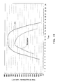
- FIG. 16 plots the solar energy density varying during one day, the conventional solar thermal electric power generation system can operate only during day time from sunrise to sunset. For this reason, the system is stopped at night and restarted in the next morning.
- FIG. 16 plots the solar energy density varying during one day at a region in North Africa. Curves plotting mean energy densities in July and December are shown respectively in FIG. 16 , and curves plotting mean energy densities varying in other months are considered to fall within the range between the two curves shown.
- the electric power generation system 101 is usually designed to have such a capacity as to generate electric power at a mean solar energy intensity level.
- the system 101 is designed to store a surplus energy in excess of a mean solar energy intensity level as thermal energy in a large-scale and expensive heat storage system 110 and release heat thus stored to generate steam as sunset approaches, thereby making it possible to continue electric power generation.
- limitations on the system investment cost and running cost limit the heat storage capacity to about 4 to about 6 hours in terms of electric power generating duration and, therefore electric power generation cannot continue day and night.
- European Patent Laid-Open Publications Nos. 0750730 and 0526816 have proposed integrated solar combined cycle electric power generation systems in each of which the above-described steam turbine electric power generation relying upon solar heat is combined with the gas turbine combined cycle electric power generation.
- Such a new concept of solar thermal electric power generation system is intended to generate electric power even during nighttime or cloudy days during which solar heat cannot be utilized by combination of the gas turbine electric power generation with the steam turbine electric power generation by utilizing steam generated in a waste heat recovery boiler.
- the system thus configured can be expected to continue electric power generation day and night.
- the integrated system can reduce the fuel consumption of gas turbine, hence, the carbon-dioxide emission amount can be reduced by the maximum use of solar heat.
- such an integrated solar combined cycle electric power generation system includes a heat collecting unit configured to generate saturated steam directly from water and supply it to a steam turbine without using a special heating medium or a heat exchanging device.
- This kind of electric power generation system according to the aforenoted European Patent Laid-Open Publication No. 0750730 is configured to mix saturated steam with steam generated from a high-pressure turbine for superheating the saturated steam before supplying to the steam turbine.
- another kind of the electric power generation system according to the aforenoted European Patent Laid-Open Publication No. 0526816 is configured to mix saturated steam with steam generated from a high-pressure turbine and then superheat the saturated steam by means of a reheater of the waste heat recovery boiler before supplying it to the steam turbine.
- the condition of steam (including temperature, pressure, wetness, dryness and the like) to be supplied to the steam turbine fluctuates, which causes the generated electric power to fluctuate. If a vigorous fluctuation occurs in the condition of steam, the waste heat recovery boiler or the steam turbine might be damaged thereby.
- the condition of steam (including temperature, pressure, dryness and the like) generated in a heat absorbing tube associated with the heat collecting unit fluctuates and steam loses its heat while being fed from the heat collecting unit to the steam turbine.
- the system according to the Laid-Open Publication No. 0750730 causes the condition of steam to fluctuate after mixing with the steam generated from the high-pressure turbine.
- the system according to the Laid-Open Publication No. 0526816 causes the condition of steam to fluctuate at the inlet side of the reheater thereby giving influence on the waste heat recovery boiler. That is, when the sunshine condition fluctuates largely or frequently, the condition of steam generated in the heat collecting unit fluctuates likewise, which makes it difficult for the whole of the solar thermal combined cycle electric power generation system to serve continuously for safe operation.
- the present invention has been made in order to solve such problems. Accordingly, it is an object of the present invention to provide a heating medium supply system which, even if a heating medium under supply in, a solar thermal electric power generation system fluctuates with time in its temperature, is capable of supplying the heating medium having a temperature fluctuation which is sufficiently suppressed through lessening or eliminating the temperature fluctuations by the time of supplying heat for steam generation. It is another object of the present invention to provide a solar thermal electric power generation system which is capable of turning steam having been generated by solar heat into a stabilized superheated condition and then supplying such steam to a steam turbine.
- the present invention provides a heating medium supply system comprising:
- the heater may be configured to operate so that the temperature of the heating medium to be measured by the temperature measuring device does not fall below a predetermined temperature.
- the heating medium supply system may have an arrangement wherein:
- the liquid heating medium continuously supplied through the heating medium supply passage flows into the temperature fluctuation suppressing device and passes through the plural heating medium passages to form respective streams.
- the streams outgoing from the respective passages are time-lag mixed together when joined together. Even when the temperature of the heating medium fluctuates, the time-lag mixing step makes it possible to reduce the range of the temperature fluctuation as well as to lower the temperature fluctuation speed. As a result, the condition of steam generated by heat of the heating medium is uniformalized throughout the operation time.
- the "time-lag mixing”, as used herein, means mixing of heating medium that continuously flows into the temperature fluctuation suppressing device with time-lags with heating medium that resides in the temperature fluctuation suppressing device after having already flowed thereinto.
- the aforementioned heater may have plural heating medium passages allowing the heating medium to pass therethrough, an inlet and an outlet for the heating medium, and heating means for heating the heating medium passing through the plural heating medium passages, whereby the heating medium flowing into the heater from the heating medium supply passage through the inlet is allowed to pass through the plural heating medium passages with time-lags to form respective streams, which are then joined together before flowing out of the heater into the heating medium supply passage through the outlet.
- This heating medium heater is preferable because the heater is capable of heating as well as time-lag mixing the heating medium at the same time.
- a solar thermal electric power generation system comprises:
- the heating medium supply system continuously supplies the heating medium in a stabilized temperature condition with its temperature fluctuation being suppressed. For this reason, the heat exchanging device can generate saturated steam in a stabilized steam condition (including temperature, pressure and wetness).
- the solar thermal electric power generation system described above may further comprise: a gas turbine; and a waste heat recovery boiler configured to generate steam by utilizing waste heat of the gas turbine and supply steam thus generated to the steam turbine, wherein: the waste heat recovery boiler comprises evaporating section having a steam drum and a superheating section; and steam generated by heating of water supplied to the waste heat recovery boiler is supplied to the steam turbine.
- the solar thermal electric power generation system thus constructed is what is called an integrated solar combined cycle electric power generation system. This electric power generation system is capable of supplying the steam turbine with stabilized steam generated by the heat exchanging device of the aforementioned heating medium supply system and stabilized steam generated by the waste heat recovery boiler.
- the solar thermal electric power generation system may have an arrangement wherein: the steam supply passage interconnects the heat exchanging device of the heating medium supply system and the steam drum to allow steam from the heat exchanging device and steam generated by the waste heat recovery boiler to be mixed together in the steam drum and then supplied to the steam turbine through the superheating section.
- This arrangement allows the superheating section of the waste heat recovery boiler to superheat saturated steam from the heat exchanging device together with steam generated by the waste heat recovery boiler.
- the solar thermal electric power generation system may have an arrangement wherein: the evaporating section and the superheating section are interconnected through a steam passage provided with a steam mixer; and the steam supply passage interconnects the heat exchanging device of the heating medium supply system and the steam mixer to allow steam from the heat exchanging device and steam generated by the waste heat recovery boiler to be mixed together in the steam mixer and then supplied to the steam turbine through the superheating section.
- this arrangement allows the superheating section of the waste heat recovery boiler to superheat saturated steam from the heat exchanging device together with steam generated by the waste heat recovery boiler.
- the superheating section of the waste heat recovery boiler may be provided with a burner for heating steam. Even when saturated steam fed to the superheating section of the waste heat recovery boiler fluctuates in its condition, this arrangement makes it possible to lessen a wetness fluctuation of steam or obtain dry steam by heating steam of high wetness by means of the burner.
- the solar thermal electric power generation system may have an arrangement wherein: the aforementioned steam supply passage is branched into a first steam passage connected to the waste heat recovery boiler and a second steam passage connected to the steam turbine without passing through the waste heat recovery boiler; and the second steam passage is provided with a superheating device for superheating steam.
- This arrangement allows the waste heat recovery boiler to superheat saturated steam from the heat exchanging device of the heating medium supply system while superheating saturated steam by means of the superheating device separately provided. Therefore, even if the gas turbine or the waste heat recovery boiler stops operating, the solar thermal electric power generation system can maintain electric power generation as long as solar heat can be collected.
- An integrated solar combined cycle electric power generation system comprises:
- the heating medium supply system may be any one of the heating medium supply systems described above.
- the integrated solar combined cycle electric power generation system may have an arrangement wherein:
- the integrated solar combined cycle electric power generation system may have an arrangement wherein:
- the superheating section of the waste heat recovery boiler may be provided with a burner for heating steam.
- the integrated solar combined cycle electric power generation system may have an arrangement wherein:
- the present invention it is possible to suppress or lessen a temperature fluctuation of a heating medium to be supplied to a heat exchanging device with its temperature fluctuating in such a system as a solar thermal electric power generation system. Also, the present invention makes it possible to suppress a fluctuation of steam condition to be supplied to a steam turbine effectively.
- FIG. 1 illustrates an integrated solar combined cycle electric power generation system 1 in which steam turbine electric power generation by a steam turbine 2 driven by utilizing part of steam generated relying upon solar heat and gas turbine electric power generation by a gas turbine 3 driven by combusting any one of various gas or liquid fuels such as natural gas are combined together.
- the electric power generation system 1 shown uses reflectors 4a of the parabolic trough type forming a heat collecting unit 4 for collecting solar heat to generate steam.
- Each of the reflectors 4a is trough-shaped having a parabolic section in a X-Y plane and is operated to reflect rays of sunlight incident thereon so as to collect them on its focal point.
- Heating medium supply piping 6 connected to the heat absorbing tubes 5 circulates the heating medium to a heat exchanging device 7 and to heat collecting units 4.
- the heat exchanging device 7 serves as an evaporator.
- the heating medium absorbs solar heat in the heat collecting units 4, heats water for generating steam in the heat exchanging device 7, and returns to the heat collecting units 4.
- the heat collecting units 4 and the heat absorbing tubes 5 form a heating system for the heating medium.
- the electric power generation system 1 has plural heat collecting zones 8a, 8b, 8c and 8d in each of which a respective heat collecting units 4 is installed. This is because even if the entire installation area of the heat collecting units (usually an area of about 1400m ⁇ 700m for the total system capable of generating electric power of 30 MW for example) is not uniformly flattened, the solar heat collecting zone is divided for effective installation of the heat collecting units. Alternatively, the zone is divided so as not to make the loop length of heating medium supply piping too long thereby to avoid an excessive pressure loss through the piping. Further, the division of the zone makes it possible to avoid stoppage of the entire system when inspecting and repairing some portion of the heat absorbing tube 5 and the heat collecting unit 4 even when the piping 5 or the unit 4 does not operate normally.
- Lines of heating medium supply pipings 6a, 6b, 6c and 6d extending from the respective heat collecting zones 8a, 8b, 8c and 8d are unified and then connected to the heat exchanging device 7.
- the heating medium supply piping 6 thus unified is provided with a heating medium heater 10 to be described later.
- the heat exchanging device 7 has an outlet joined to a return piping 9 connected to the heat collecting zones.
- the "heating medium supply piping 6" includes the return piping 9 also.
- the heating medium supply piping 6 is provided with a circulating pump 9p for circulating the heating medium. Though the single pump 9p is shown in FIG.
- a plurality of such pumps may be used for sharing a pressure loss in the piping as required if the heating medium supply piping 6 is too long and large.
- the input of heat to the heat exchanging device 7 can be adjusted, and thereby the amount of steam to be generated by the heat exchanging device 7 can be controlled.
- the heat collecting units 4, heating medium supply piping 6, heat exchanging device 7 and heating medium heater 10 form a heating medium supply system 12.
- Electric power generation is conducted by the steam turbine 2 and the gas turbine 3, as described above.
- the two turbines 2 and 3 are coupled to respective electricity generators G.
- the electric power generation system 1 is provided with a waste heat recovery boiler 13. High temperature combusted gas exhausted from the gas turbine 3 is supplied to the waste heat recovery boiler 13 to heat the supplied water for generating steam and then emitted into the atmosphere from a stack 15 through the exhaust gas piping 14.
- the steam turbine 2 is driven both by the steam generated from the heat exchanging device 7 and the steam generated from the waste heat recovery boiler 13.
- the steam having driven the steam turbine 2 is condensed into water by a condenser 16 and then fed through a water supply piping 18 with a pressure by means of a water supply pump 17. Specifically, firstly, the condensed water is heated by a supplied water heater 19 and then deaerated by a deaerator 20. Subsequently, water is passed through branched lines and supplied to the waste heat recovery boiler 13 and the heat exchanging device 7 by means of respective pumps 21a and 21b. The steam generated by the heat exchanging device 7 and the steam generated by the waste heat recovery boiler 13 are joined together and supplied to the steam turbine 2 through a unified steam supply piping 22.
- the unified steam supply piping 22 extends to pass through a superheater 25 of the waste heat recovery boiler 13.
- the flow rate ratio of water to be supplied to the waste heat recovery boiler 13 and to the heat exchanging device 7 is controlled, in accordance with electricity demand and actually collected solar thermal energy, based on steam production program determined at a planning stage of the electric power generation system.
- An exemplary basic construction of the aforementioned waste heat recovery boiler 13 comprises an economizer (preheater) 23, an evaporator 24 having a steam drum 26, and a superheater 25.
- the steam generated by the heat exchanging device 7 is in a saturated condition. Therefore, such saturated steam need to be superheated by utilizing the superheater 25 of the waste heat recovery boiler 13 before being supplied to the steam turbine 2.
- a steam supply piping 27 is provided to interconnect the steam outlet of the heat exchanging device 7 and the steam drum 26 provided upstream of the superheater 25.
- the saturated steam supplied from the heat exchanging device 7 to the steam drum 26 through the steam supply piping 27 is mixed with steam generated by the evaporator 24 of the waste heat recovery boiler 13 within the steam drum 26.
- the steam thus mixed is fed to the superheater 25 and superheated.
- the superheater 25 is designed and manufactured to have the capability (heating area) of heating the total amount of the saturated steam from the heat exchanging device 7 and the saturated steam from the evaporator 24 to a predetermined superheat temperature, so that the waste heat recovery boiler 13 can supply the steam turbine 2 with the superheated steam having stabilized properties.
- the aforementioned steam supply piping 27 is preferably provided with a flow control valve 28.
- the flow control valve 28 is controlled so as to prevent the steam supply rate to the waste heat recovery boiler 13 from changing rapidly and largely because of a rapid decrease in collected solar heat due to shading of sunlight by clouds during daytime, a steep drop in the solar heat collecting efficiency due to bending of reflectors in the heat collecting units 4 caused by wind pressure, or a rapid decrease in the solar heat after sunset.
- the flow control valve 28 is controlled so that the amount of generated steam that begins increasing with the rising sun may be kept within an allowable range of the waste heat recovery boiler 13. Further, the flow control valve 28 is controlled to close the steam supply piping 27 particularly after sunset because the steam in the steam supply piping 27 naturally runs out.
- the heating medium supply piping 6 of the integrated solar combined cycle electric power generation system 1 is provided with the aforementioned heating medium heater 10 for heating the heating medium so that the temperature of the heating medium reaching the heat exchanging device 7 is sufficiently recovered even if the temperature of the heating medium falls in the heat collecting units 4.
- the heating medium supply piping 6 is preferably provided with a heating medium mixer 11 as shown in FIG. 1 for further suppressing the temperature fluctuations of the heating medium.
- the heating medium mixer 11 is described later.
- FIG. 2 shows the aforementioned heating medium heater 10 in detail.
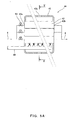
- the heating medium heater 10 comprises a heating medium supply piping 6 bent into a helical structure and a hood 36 covering this helical structure.
- Heating means 37 such as a burner, is provided below the helical structure for heating the helical structure.
- the top of the hood defines an opening 36a for emitting combustion gas from the burner or the like and for the heating medium supply piping 6 to extend therethrough.
- the helical structure may have, for example, two or more helices laid upon another without limitation to the structure shown.
- the heating medium supply piping 6 may be formed into a simple zigzag shape (successively and repeatedly folded shape) or a like shape. Further, the heating medium supply piping 6 thus shaped may be formed with heat transfer fins.
- the heating medium heater 10 may employ various other structures.
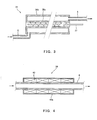
- a heating medium heater 38 shown in FIG. 3 has a structure wherein a part of the heating medium supply piping 6 has a double-pipe structure comprising an inner pipe 38a provided therein with the heating means 37 such as a burner and an outer pipe 38b which, together with the inner pipe 38a, defines a passage therebetween for the heating medium to pass therethrough.
- a heating medium heater 39 shown in FIG. 4 has heating means 40, such as an electric heater, wrapping the outer periphery of the heating medium supply piping 6, and a heat insulating member 40a covering the outer peripheral surface of the heating means 40.
- heating means 40 such as an electric heater
- Any other suitable heating means is applicable without limitation to this arrangement.
- high-temperature steam may be employed as a heat source for heating instead of the electric heater.
- such an arrangement is possible wherein the outer periphery of the heating medium supply piping 6 is wrapped with a piping which allows high-temperature steam generated by the waste heat recovery boiler 13 to be fed therethrough.
- the heating medium supply piping 6 is provided with temperature measuring devices 29 which are provided on the upstream side and the downstream side of the heating medium heater 10 for successive measurements of the temperature of the heating medium.
- the heating medium heater 10 is actuated when an abnormal temperature fall of the heating medium is detected by the upstream side temperature measuring device 29.
- the heating medium heater 10 is feedback-controlled according to the result of measurement by the downstream side temperature measuring device 29.
- the heating medium heater 10 is feedback-controlled so as to keep the temperature of the heating medium flowing at the inlet of the heat exchanging device 7 at a value of about 395°C maximum.
- the heating medium heater 10 may be controlled by a separately-provided control device 70 ( FIG. 1 ) so that the temperature of the heating medium does not fall below a predetermined allowable minimum temperature.
- heating medium heater 10 it is possible to actuate the heating medium heater 10 when a substantial fall in the temperature of the heating medium (about 40°C or more for example) is forecast based on observation of shading by clouds by, for example, a weather satellite probing weather conditions of a region around the solar heat collecting zone.
- the heating medium heater 10 which exhibits the effect of suppressing the temperature fluctuation of the heating medium in daytime, makes it possible to start up the heating medium supply system 12 quickly after sunrise by heating the heating medium of which temperature is lowered after sunset while circulating the heating medium.
- the heating medium supply piping 6 is provided with the aforementioned heating medium mixer 11 configured to suppress the temperature fluctuation of the heating medium, as shown in FIG. 1 .
- the heating medium mixer 11 is formed with a heating medium inlet 11a connected to the upstream side of the heating medium supply piping 6 and a heating medium outlet 11b formed separately from the inlet 11a and connected to the downstream side of the heating medium supply piping 6.
- the heating medium mixer 11 is formed therein with plural heating medium passages. The details of the heating medium mixer 11 are described in the international patent application ( PCT/JP2006/312162 ) filed by the applicant of the instant application. While the present embodiment has the heating medium mixer 11 provided downstream of the heating medium heater 10, the heating medium mixer 11 may be provided upstream of the heating medium heater 10.
- the heating medium flowing into the heating medium mixer 11 with its temperature fluctuating moment by moment is time-lag mixed within the heating medium mixer 11. Specifically, portions of the heating medium that start flowing into the heating medium mixer 11 at a certain point of time are passed through the different heating medium passages to form different streams within the heating medium mixer 11, thus providing such a distribution of streams as to allow some portions to flow out through the outlet 11b for a relatively short time and simultaneously cause other portions to reside in the passages of the heating medium mixer 11 for a relatively long time. Since fresh portions of the heating medium newly flow into the heating medium mixer 11 through the inlet 11a continuously, the portions of the heating medium that flowed into the mixer 11 in the past and the portions that have newly flowed thereinto are mixed together incessantly.
- time-lag mixing By subjecting the heating medium in order to time-lag mixing, the temperature fluctuation range of the heating medium is reduced and the temperature fluctuation speed is lowered.
- the heating medium mixer 11 performing the time-lag mixing functions as a temperature fluctuation suppressing device for the heating medium.
- the heating medium supply piping 6 is preferably provided with temperature measuring devices 29 on respective of the upstream side and the downstream side of the heating medium mixer 11 for successive measurements of the temperature of the heating medium.
- These temperature measuring devices 29 make it possible to detect temperature fluctuations of the heating medium in the heating medium supply piping 6 on the upstream and downstream sides of the heating medium mixer 11.
- Signals indicative of temperature fluctuations of the heating medium on respective of the upstream and downstream sides of the heating medium mixer 11 are sent to the control device 70. By comparison between these signals, it is possible to monitor the degree of temperature fluctuation suppressing effect performed by the heating medium mixer 11.
- Such heating medium heater 10 and heating medium mixer 11 as described above may be provided on each of the lines of heating medium supply pipings 6a, 6b, 6c and 6d associated with the respective heat collecting zones 8a, 8b, 8c and 8d, unlike FIG. 1 , the heating medium heater 10 and the heating medium mixer 11 being independent of each other. As illustrated below, it is possible to employ a unified structure comprising the heating medium heater 10 and the heating medium mixer 11.
- FIGs. 5A and 5B A heating medium heater 41 shown in FIGs. 5A and 5B is given with the function of heating the heating medium as well as the function of mixing the heating medium.
- FIG. 5A is a front elevational view of the heating medium heater 41 with its hood 43 to be described below partially cutaway; and
- FIG. 5B is a sectional view taken on line V-V of FIG. 5A .
- the heating medium mixing function of the heating medium heater 41 is performed relying upon plural heating medium passages, like the above-described heating medium mixer 11.
- the heating medium passages of the heating medium heater 41 are each formed of a respective one of independent containers 42.
- the containers 42 have substantially equal volume.
- Each of the containers 42 has an inlet hole 42a and an outlet hole 42b.
- the inlet holes 42a are each connected to a respective one of branch pipings branched off from the upstream side portion of the heating medium supply piping 6.
- the branch pipings are provided with respective flow control valves 54.
- the openings of the respective flow control valves 54 are controlled to allow the heating medium to flow into the respective containers 42 at different flow rates.
- the outlet holes 42b are each connected to a respective one of branch pipings branched off from the downstream side portion of the heating medium supply piping 6.
- Streams of the heating medium that have flowed out of the respective containers 42 with time-lags begin being mixed together in a unified portion of the heating medium supply piping 6 on the downstream side. That is, the heating medium is time-lag mixed, whereby the temperature fluctuation range of the heating medium is reduced and the temperature fluctuation speed is lowered.
- the heating medium heater 41 has the hood 43 covering the plural containers 42.
- Heating means 44 such as a burner, is provided below the assembly of the containers 42 within the hood 43 for heating the containers 42.
- the top of the hood 43 defines an opening 43a for emitting combustion gas from the burner or the like. The heating medium flowing in the containers 42 is heated by the heating means 44.
- the containers have different kinds of volume and the heating medium is forced to flow into the containers at substantially equal flow rate.
- the provision of the flow control valves on the inlet side is not particularly required.
- Such a heating medium fluctuation suppressing device can effectively time-lag mix the heating medium having flowed thereinto, thereby suppressing the temperature fluctuation of the heating medium.
- the integrated solar combined cycle electric power generation system 1 has a steam supply line to the steam turbine 2 which is also provided with a device for suppressing a fluctuation of the steam condition resulting from the temperature fluctuation of the heating medium.
- the superheater 25 of the waste heat recovery boiler 13 is provided with an auxiliary burner 30 for realizing a stabilized superheated condition of steam flowing on the inlet side of the steam turbine 2 even when the steam condition fluctuates.
- Such steam condition fluctuation can be suppressed, without the provision of the auxiliary burner 30, by the aforementioned heating medium heater 10 preventing the temperature of the heating medium from falling.
- the provision of the auxiliary burner 30 is preferable because the burner 30 can further enhance the effect of suppressing the steam condition fluctuation thereby turning the steam condition into a stabilized superheated condition.
- the condition of steam to be fed to the superheater 25 fluctuates as a result of a fluctuation in the condition of saturated steam to be supplied from the heat exchanging device 7 to the steam drum 26.
- the ability of the superheater 25 can be enhanced. Since the solar energy is maximized in daytime, the gas turbine 3 is often operated economically by a partial-load operation with reducing the load on the gas turbine 3. In such a case, even when a significant fall occurs in the temperature of the heating medium abruptly, it is possible to actuate the auxiliary burner 30 to lessen the resulting fluctuation in the condition of superheated steam, thereby keeping the steam condition constant.
- the steam supply piping 27 for supplying saturated steam generated by the heat exchanging device 7 may be connected to an additional steam mixer 31 instead of the steam drum 26, as shown in FIG. 6 .
- the steam mixer 31 may comprise either a tank having a relatively large volume or a tank having an internal volume which is variable in accordance with the internal pressure of the tank.
- the tank of the steam mixer 31 has a large volume as compared to the aforementioned steam drum 26.
- the steam mixer 31 is effective, in cases where the amount of steam to be generated by the waste heat recovery boiler 13 is planned being equal to or slightly larger than the amount of steam being fed from the heat exchanging device 7, or in cases where a sufficient amount of exhaust gas is available from the gas turbine 3 operating in a rated condition constantly.
- the electric power generation system shown in FIG. 6 is the same as the electric power generation system 1 shown in FIG. 1 except the feature that the steam mixer 31 is added and saturated steam from the heat exchanging device 7 is fed to the steam mixer 31 instead of the steam drum 26. For this reason, same reference characters are used to designate similar elements except the steam mixer 31 throughout FIGs. 1 and 6 in order to omit the description thereof.
- the steam mixer 31 is preferably provided with a perforated plate having multiple perforations which is positioned to obstruct the steam flow path in order to enhance the steam mixing effect.
- a perforated plate having multiple perforations which is positioned to obstruct the steam flow path in order to enhance the steam mixing effect.
- the steam mixer 31 may have a configuration wherein: plural perforated plates which are laid on another so as to be displaceable relative to each other are positioned in the steam mixer 31 to obstruct the steam flow path; each of the perforated plates has plural perforations; and by displacing the plural perforated plates relative to each other in the plane of contact therebetween as laid on another, the degree of overlap between the perforations of one perforated plate and those of another perforated plate varies and, hence, the percentage open area of all the perforations is adjusted.
- FIG. 7 illustrates an electric power generation system wherein saturated steam generated by the heat exchanging device 7 is superheated by means of a superheating device 32 which is provided independently of the waste heat recovery boiler 13.
- the superheating device 32 functions to heat saturated steam by combusting any one of various gas or liquid fuels such as natural gas for example.
- the steam supply piping 27 connected to the outlet of the heat exchanging device 7 is branched into branch pipings at a location downstream of the flow control valve 28.
- One branch piping (hereinafter referred to as "first steam supply piping") 33 is connected to the steam drum 26 of the waste heat recovery boiler 13 as in FIG. 1 .
- the other branch piping (hereinafter referred to as "second steam supply piping) 34 is joined to the unified steam supply piping 22 configured to supply the steam turbine with superheated steam from the waste heat recovery boiler 13 and then connected to the steam turbine 2.
- the second steam supply piping 34 is provided with the aforementioned superheating device 32.
- the solar thermal electric power generation system is the same as the electric power generation system 1 shown in FIG. 1 except the feature that the second steam supply piping 34 and the superheating device 32 are provided. For this reason, same reference characters are used to designate similar elements except the second steam supply piping 34 and the superheating device 32 throughout FIGs. 1 and 7 in order to omit the description thereof.
- the first steam supply piping 33 is provided with a stop valve 35 at a location upstream of the steam drum 26 and the unified steam supply piping 22 provided with a stop valve 35 at a location upstream of the joint with the second steam supply piping 34.
- the second steam supply piping 34 is provided with stop valves 35 at respective locations upstream and downstream of the superheating device 32.
- the steam turbine 2 can be supplied with superheated steam by using the superheating device 32 to continue electric power generation as long as solar heat can be collected.
- An electric power generation system shown in FIG. 8 is a system constructed by providing the electric power generation system 1 shown in FIG. 1 with a steam fluctuation suppressing device 45 configured to mix saturated steam from the heat exchanging device 7 for suppressing a fluctuation of its steam condition.
- This electric power generation system is the same as the electric power generation system 1 shown in FIG. 1 except the feature that the steam supply piping 27 is provided with the steam fluctuation suppressing device 45. For this reason, same reference characters are used to designate similar elements except the steam fluctuation suppressing device 45 throughout FIGs. 1 and 8 in order to omit the description thereof.
- the steam fluctuation suppressing device 45 forms a contrivance to suppress a steam condition fluctuation resulting from a temperature fluctuation of the heating medium.
- the steam fluctuation suppressing device 45 serves to obtain saturated steam having a substantially stabilized wetness by the aforementioned time-lag mixing of saturated steam that is fed thereto while fluctuating in wetness.
- the function of heating saturated steam to a superheated condition relies upon the superheater 25, auxiliary burner 30 or the superheating device 32 (FIG. 14), which are provided downstream of the steam fluctuation suppressing device 45.
- the saturated steam supplied to the steam drum 26 after having passed through the steam fluctuation suppressing device 45 has a wetness fluctuation suppressed and stabilized therefore.
- the steam drum 26 such saturated steam having a stabilized wetness is mixed with saturated steam having a stabilized wetness that is generated by the waste heat recovery boiler 13.
- the aforementioned devices 25, 30 and 32 provided downstream of the steam drum for superheating steam can perform their respective operations stably. Therefore, even if the steam fluctuation suppressing device 45 is used instead of the aforementioned heating medium heater 10 or heating medium mixer 11 of the heating medium supply system 12, the steam fluctuation suppressing device 45 can exhibit the steam fluctuation suppressing effect.
- the steam fluctuation suppressing device 45 may be used along with the heating medium heater 10 and the heating medium mixer 11.
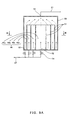
- FIGs. 9A to 12B show steam fluctuation suppressing devices 45, 46, 47 and 48 of different types. Any one of these steam fluctuation suppressing devices is formed with a steam inlet (for example an inlet hole 52) connected to an upstream side of the steam supply piping 27 and a steam outlet (for example an outlet hole 53) which is separate from the inlet and is connected to a downstream side of the steam supply piping 27.
- Each of the steam fluctuation suppressing devices has various contrivances in order to time-lag mix saturated steam sufficiently within the device. That is, each steam fluctuation suppressing device is configured to cause a portion of introduced saturated steam to reside within the device for a relatively long time and to be sufficiently mixed with following saturated steam that flows into the device, thereby achieving effective time-lag mixing.
- the steam fluctuation suppressing device is configured to allow introduced saturated steam to pass through plural steam passages formed therein in different times to form respective streams and join together each of the streams of steam having passed through the respective passages, thereby achieving the time-lag mixing.
- the steam fluctuation suppressing device 45 shown in FIGs. 9A and 9B employs a tank 50 having therein plural cells 49 forming plural steam passages as a steam passage forming member which form different steam passages.
- plural cylindrical partition walls 51 having free upper edges are arranged concentrically as spaced from each other on the bottom of the cylindrical tank 50.
- the space between the peripheral wall of the tank and the cylindrical partition wall 51 adjacent thereto and the spaces between adjacent partition walls 51 form respective of the steam passages 49.
- the height of the upper edge of each cylindrical partition wall 51 is lower than that of the ceiling of the tank 50.
- the cells (steam passages) 49 communicate with each other through the space defined between the ceiling of the tank 50 and the upper edges of the cylindrical partition walls 51.
- the bottom of the tank 50 defines steam inlet holes 52 at locations corresponding to the respective cells 49, while the ceiling of the tank 50 defines a single steam outlet hole 53 connected to a downstream side portion of the steam supply piping 27. Streams of steam having separately passed through the respective steam passages 49 are joined and mixed together at the outlet hole 53. While the steam passage forming member shown in FIG. 9A has four steam passages 49a, 49b, 49c and 49d, there is no limitation to the number of steam passages as long as the number is not less than two. A larger number of stream passages is more preferable from the viewpoint of effective time-lag mixing of steam.
- the inlet holes 52 are each connected to a respective one of branch pipings branched off from the upstream side portion of the steam supply piping 27, which are each provided with a respective one of flow control valves 54 for controlling the flow rate of steam flowing through a respective one of the branch pipings.
- all the cells 49 have substantially equal volume. Under this condition, the openings of the flow control valves 54 are controlled to cause steam to flow into the different cells 49 at different flow rates. As a result, different time lengths are required for portions of steam that start flowing into the respective cells 49a, 49b, 49c and 49d at a certain point of time to reach the outlet hole 53.
- the outlet hole 53 may be provided with a mixing device or a stirring device for further mixing the streams of steam having flowed out of the respective steam passages with time-lags after joining.
- a mixing device such as a screw propeller, and a forced jetting device.
- An electric motor or the like for driving such a rotor is preferably located outside the tank or the steam passages.
- a static member or construction may be fixed as to change the forms of steam streams.
- stationary blades may be attached to the inner wall surface of the flow path.
- any desired flow rate ratio can be selected without limitation to such a ratio of integer.
- portions of steam may be passed through some of the steam passages at equal flow rate when necessary.
- such a steam fluctuation suppressing device has a tank in which plural cylindrical partition walls are arranged concentrically as spaced from each other, like the steam fluctuation suppressing device 45 shown in FIG. 9 .
- the space between the peripheral wall of the tank and the cylindrical partition wall adjacent thereto and the spaces between adjacent partition walls form respective of steam passages.
- the cylindrical partition walls are spaced from each other to form steam passages (cells) having a volume ratio of 1:2:3:4 in the order from the innermost passage side for example.
- Branch pipings branched off from the upstream side portion of the steam supply piping 27 are connected to respective of inlet holes of the tank, but each of the branch pipings is not provided with the flow control valve 54.
- the steam fluctuation suppressing device is configured to allow steam to flow into all the steam passages (cells) at substantially equal flow rate to form respective streams and cause the resulting streams to be joined together before flowing out from the outlet hole into the downstream side portion of the steam supply piping 27.
- Such a steam fluctuation suppressing device also can time-lag mix steam before flowing out of the device, hence, suppress the wetness fluctuation of steam. This effect is described more specifically.
- the flow rate of the whole of steam flowing into the steam fluctuation suppressing device through the steam supply piping 27 is V and the volume ratio between the first and up to nth steam passages is 1:2:3:...n.
- the nth portion of steam that flows into the nth steam passage having a volume nW at a flow rate v V/n, at the same time when the first portion flows into the first steam passage, flows out of the nth steam passage after lapse of time nt1.
- the portions of steam flowing into all the steam passages at the same time i.e., the portions of steam having substantially equal wetness flow out of the respective steam passages after lapse of different time periods and are then joined and mixed together at the outlet hole.
- steam having flowed into the steam fluctuation suppressing device is effectively time-lag mixed, so that the wetness fluctuation of steam is suppressed.
- the volume ratio between the steam passages is a ratio of integers in this embodiment, any desired volume ratio can be selected without limitation to such a ratio of integer. Also, some of the steam passages may have equal volume when necessary.
- the shape of the tank 50 of the above-described steam fluctuation suppressing device is not limited to a cylindrical shape. Any other various shapes can be employed including a prismatic shape and a spherical shape in addition to the cylindrical shape. Though the cylindrical partition walls 51 forming the cells in the tank 50 are arranged concentrically, the partition walls 32 may be arranged eccentrically without limitation to such a concentric arrangement. Each of the steam passages need not necessarily have a uniform sectional shape in the direction of the flow of steam. The sectional shape may be scaled up or down, or each passage need not be straight but may be curved or meandered.
- the steam fluctuation suppressing device may employ any other suitable structure without limitation to the structure of the steam fluctuation suppressing device 45 shown in FIG. 9A .
- a steam fluctuation suppressing device 46 shown in FIG. 10 includes plural lateral partition walls 56 spaced vertically from each other to partition the internal space of a tank 55 into plural steam passages (cells) 57.
- the lateral partition walls 56 are so spaced from each other that all the cells 57 have substantially equal volume.
- Each of the cells 57 has one end defining an inlet hole 52 and an opposite end defining an outlet hole 58.
- the inlet hole 52 and the outlet hole 58 are not opposed to each other, and the outlet hole 58 is formed offset from the central axis of the inlet hole 52.
- This arrangement is capable of preventing a portion of steam flowing into each cell 57 through the inlet hole 52 from flowing out through the outlet hole in a very short time thereby causing that the steam can reside within the cell 57 as long as possible.
- offset positioning of the outlet hole 58 from the central axis of the inlet hole 52 is applicable to the cells or tanks shown in other figures without limitation to the steam fluctuation suppressing device 46 shown in FIG. 10 .
- the present invention is not limited to this arrangement.
- partition walls may be made to form cells arranged radially like a sectional view of a citrus fruit.
- the steam fluctuation suppressing device 46 is connected to the upstream side portion of the steam supply piping 27 in the same manner as in FIG. 9A ; specifically, the plural inlet holes 52 are each connected to a respective one of branch pipings branched off from the upstream side portion of the steam supply piping 27, the branch pipings being each provided with a flow control valve 54.
- the openings of the flow control valves 54 are controlled so as to allow portions of steam to flow into the respective cells 57 at different flow rates.
- the downstream side portion of the steam supply piping 25 is branched into branch pipings each connected to a respective one of the plural outlet holes 58, as shown in FIG. 10 .
- this unified piping portion may be provided with a mixing device or a stirring device.
- the steam fluctuation suppressing device 46 also allows steam having flowed thereinto to be effectively time-lag mixed, thereby suppressing the wetness fluctuation of steam.
- the plural cells have different kinds of volume and portions of steam are made to flow into the respective cells at substantially equal flow rate.
- the inlet of each cell need not necessarily be provided with the flow control valve.
- Such a steam fluctuation suppressing device also can effectively time-lag mix steam having flowed thereinto, thereby suppressing the wetness fluctuation of steam.
- the steam fluctuation suppressing device is not limited to the type shown in FIG. 9A or 10 having plural cells within a single tank, but may comprise plural independent containers.
- FIG. 11 shows such a steam fluctuation suppressing device 47 comprising plural independent containers 59.
- the containers 59 form respective cells (steam passages) and have substantially equal volume.
- Each of the containers 59 is formed with an inlet hole 52 at its bottom (or at its top or sidewall) and a steam outlet hole 58 at its top (or at its bottom or sidewall).
- the inlet holes 52 which are like the corresponding ones shown in FIG. 9A or 10 , are each connected to a respective one of branch pipings branched off from the upstream side portion of the steam supply piping 27, the branch pipings being each provided with a flow control valve 54.
- the respective flow control valve 54 is controlled so as to allow each portion of steam to flow into the respective cell 59 at different flow rate.
- the outlet holes 58 which are like the corresponding ones shown in FIG. 10 , are each connected to a respective one of branch pipings branched off from the downstream side portion of the steam supply piping 27. Streams of steam that have flowed out of the respective cells 59 with time-lags begin being mixed together in the unified downstream side portion of the steam supply piping 27.
- this unified portion of the steam supply piping 27 may be provided with a mixing device or a stirring device.
- the steam fluctuation suppressing device 47 also can effectively time-lag mix steam having flowed thereinto, thereby suppressing the wetness fluctuation of steam. Further, since each of the steam passages comprises an independent single container, it is possible to eliminate partition walls for partitioning the tank into cells, hence, make it easy to the manufacture the steam fluctuation suppressing device.
- each of the above-described containers 59 may have any of various shapes such as a cylindrical shape, a prismatic shape, and a spherical shape. Since a single independent container forms each of the steam passages, the containers can be made to have different kinds of volume easily.
- the containers can be formed by using piping sections having different diameters or different lengths, or like materials.
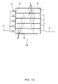
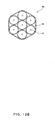
- a steam fluctuation suppressing device 48 shown in FIGs. 12A and 12B comprises the containers 59 assembled together as shown.
- the steam fluctuation suppressing device 48 has substantially the same structure as the steam fluctuation suppressing device 47 shown in FIG. 11 except that the plural containers 59 are compactly assembled. For this reason, same characters are used to designate similar parts throughout FIG. 11 and FIGs. 12A and 12B in order to omit detailed description thereof.
- This steam fluctuation suppressing device 48 can save the installation space therefor.
- An electric power generation system shown in FIG. 13 is a system constructed by providing the electric power generation system shown in FIG. 6 with the above-described steam fluctuation suppressing device 45 (or 46, 47 or 48).
- This electric power generation system is the same as the electric power generation system shown in FIG. 6 except the feature that the steam supply piping 27 is provided with the steam fluctuation suppressing device 45. For this reason, same characters are used to designate similar elements except the steam fluctuation suppressing device 45 throughout FIGs. 6 and 13 in order to omit the description thereof.
- saturated steam from the heat exchanging device 7 having a wetness fluctuation suppressed by passage of steam through the steam fluctuation suppressing device 45 is mixed with saturated steam having a stabilized wetness generated by the waste heat recovery boiler 13 within the steam mixer 31 located downstream. Accordingly, the superheater 25 and the auxiliary burner 30, which are located downstream of the steam mixer 31 for superheating steam, can perform their respective operations stably.
- An electric power generation system shown in FIG. 14 is a system constructed by providing the electric power generation system shown in FIG. 7 with the above-described steam fluctuation suppressing device 45 (or 46, 47 or 48).
- the steam supply piping 27 is provided with the steam fluctuation suppressing device 45 at a location upstream of the branch point of the first and second steam supply pipings 33 and 34 and downstream of the flow control valve 28.
- This electric power generation system is the same as the electric power generation system shown in FIG. 7 except the provision of the steam fluctuation suppressing device 45. For this reason, same characters are used to designate similar elements except the steam fluctuation suppressing device 45 throughout FIGs. 7 and 14 in order to omit the description thereof.
- saturated steam having a wetness fluctuation suppressed by passage of steam through the steam fluctuation suppressing device 45 is mixed with saturated steam having a stabilized wetness generated by the waste heat recovery boiler 13 within the steam drum 26 located downstream of the first steam piping 33. Accordingly, the superheater 25 and the auxiliary burner 30, which are located downstream of the steam drum 26 for superheating steam, can perform their respective operations stably. Also, the superheating device 32 located downstream of the second steam supply piping 34 turns saturated steam having a wetness fluctuation suppressed by the steam fluctuation suppressing device 45 into superheated steam and, hence, its operating condition is stabilized.
- the heating medium heaters 10, 38, 39 and 41 ( FIGs. 2 to 5B ) described above may be provided alone. Alternatively, these heaters of same type and/or different type may be provided in combination in a serial arrangement or a parallel arrangement. Likewise, the steam fluctuation suppressing devices 45 to 48 ( FIGs. 9A to 12B ) described above may be provided alone. Alternatively, these devices of same type and/or different type may be provided in combination in a serial arrangement or a parallel arrangement.
- the heating medium supply system 12 is applicable not only to an integrated solar combined cycle electric power generation system but also to other electric power generation system applying steam turbine which is not combined with any gas turbine. Besides these electric power generation systems, the heating medium supply system is applicable to any system which is inevitably accompanied with temperature fluctuation of the heating medium.
- heat collecting units illustrated above comprises reflectors 4a of the parabolic trough type
- a heat collecting unit comprising reflectors of any other type than the parabolic trough type or a heat collecting unit of the so-called central tower type.
- the present invention makes it possible to suppress or lessen a temperature fluctuation of a liquid heating medium which is supplied to a heat exchanging device while fluctuating in temperature in such a system as a solar thermal electric power generation system by a simple construction. Therefore, the present invention is useful for a system which conducts electric power generation or the like using a heating medium of which temperature fluctuation is inevitable.
Landscapes
- Engineering & Computer Science (AREA)
- Chemical & Material Sciences (AREA)
- Combustion & Propulsion (AREA)
- Mechanical Engineering (AREA)
- General Engineering & Computer Science (AREA)
- Life Sciences & Earth Sciences (AREA)
- Sustainable Development (AREA)
- Sustainable Energy (AREA)
- Physics & Mathematics (AREA)
- Thermal Sciences (AREA)
- Engine Equipment That Uses Special Cycles (AREA)
- Air-Conditioning For Vehicles (AREA)
Abstract
A heating medium supply system is provided which is capable of sufficiently suppressing a temperature fluctuation of a heating medium, by the time when a heat exchanging device recovers heat of the heating medium, by leveling the temperature fluctuation fluctuating inevitably with time. The heating medium supply system includes: a heat collecting unit (4) configured to heat a liquid heating medium by sunlight; a heat exchanging device (7) configured to heat water supplied thereto by means of the heating medium supplied thereto from the heat collecting unit (4); heating medium supply piping (6) for supplying the heating medium from the heat collecting unit (4) to the heat exchanging device (7); and a heating medium heater (10) for heating the heating medium and a temperature measuring device (29) configured to measure a temperature of the heating medium, which are provided on the heating medium supply piping (6).
Description
- The present invention relates to a solar thermal electric power generation system including integrated solar combined cycle electric power generation, and a heating medium supply system. More specifically, the present invention relates to: a solar thermal electric power generation system configured to generate steam by means of a heating medium heated by solar heat and drive a steam turbine by means of steam thus generated to generate electric power; and a heating medium supply system used to serve various purposes such as to generate steam to be supplied to such a solar thermal electric power generation system.
- A conventional solar thermal electric power generation system 101 shown in FIG. 15 has a configuration wherein: sunlight is collected by means of concentrating type heat collecting unit (hereinafter referred to as "heat collecting unit" simply) 102; a heating medium absorbs collected sunlight as thermal energy; and the heating medium is supplied to a heat exchanging device 103 to generate steam by utilizing heat of the heating medium. Saturated steam generated by the heat exchanging device 103 is then superheated by means of a superheater 104. A steam turbine 105 is driven by such superheated steam to generate electric power. In the figure, reference characters 106 and 107 denote an electricity generator and a condenser, respectively.
- Methods of collecting incidental solar radiation are roughly classified into the central receiver type and the parabolic trough type. The heat collecting unit 102 of the parabolic trough type uses trough-shaped reflectors 102a having a parabolic section in a X-Y plane and configured to reflect sunlight thereon to collect them on its focal point. Heat absorbing tubes 108 each extending through the focal points of
reflectors 4a along the Z-axis allow a heating medium to pass therethrough to collect solar heat. The heat absorbing tubes 108 and heating medium supply piping 109 connected thereto allow the heating medium to circulate between a heat exchanging device and the heat collecting unit. A special synthetic oil is generally used as the heating medium. The heating medium absorbs, for example, solar heat to reach high-temperature condition of about 400°C, releases heat to generate steam in the heat exchanging device 103 thereby to assume a low-temperature condition of about 300°C, and returns to the heat collecting unit 102. - As can be seen from
FIG. 16 plotting the solar energy density varying during one day, the conventional solar thermal electric power generation system can operate only during day time from sunrise to sunset. For this reason, the system is stopped at night and restarted in the next morning.FIG. 16 plots the solar energy density varying during one day at a region in North Africa. Curves plotting mean energy densities in July and December are shown respectively inFIG. 16 , and curves plotting mean energy densities varying in other months are considered to fall within the range between the two curves shown. - As shown, the intensity of solar thermal energy reaching the heat collecting unit 102 varies from zero to maximum during one day. Therefore, the electric power generation system 101 is usually designed to have such a capacity as to generate electric power at a mean solar energy intensity level. As often the case, the system 101 is designed to store a surplus energy in excess of a mean solar energy intensity level as thermal energy in a large-scale and expensive heat storage system 110 and release heat thus stored to generate steam as sunset approaches, thereby making it possible to continue electric power generation. Actually, however, limitations on the system investment cost and running cost limit the heat storage capacity to about 4 to about 6 hours in terms of electric power generating duration and, therefore electric power generation cannot continue day and night.
- In an attempt to solve this problem, for example, European Patent Laid-Open Publications Nos.
0750730 and0526816 have proposed integrated solar combined cycle electric power generation systems in each of which the above-described steam turbine electric power generation relying upon solar heat is combined with the gas turbine combined cycle electric power generation. Such a new concept of solar thermal electric power generation system is intended to generate electric power even during nighttime or cloudy days during which solar heat cannot be utilized by combination of the gas turbine electric power generation with the steam turbine electric power generation by utilizing steam generated in a waste heat recovery boiler. The system thus configured can be expected to continue electric power generation day and night. Also, the integrated system can reduce the fuel consumption of gas turbine, hence, the carbon-dioxide emission amount can be reduced by the maximum use of solar heat. - However, such an integrated solar combined cycle electric power generation system includes a heat collecting unit configured to generate saturated steam directly from water and supply it to a steam turbine without using a special heating medium or a heat exchanging device. This kind of electric power generation system according to the aforenoted European Patent Laid-Open Publication No.
0750730 is configured to mix saturated steam with steam generated from a high-pressure turbine for superheating the saturated steam before supplying to the steam turbine. On the other hand, another kind of the electric power generation system according to the aforenoted European Patent Laid-Open Publication No.0526816 is configured to mix saturated steam with steam generated from a high-pressure turbine and then superheat the saturated steam by means of a reheater of the waste heat recovery boiler before supplying it to the steam turbine. - Regardless of whether the conventional solar thermal electric power generation system or the integrated solar combined cycle electric power generation system, there exists an unavoidable problem. This problem is associated with the condition of solar radiation onto the surface of the Earth incidentally changing (with time) during daytime. In the solar heat collecting unit, heat transfer from solar heat to steam or other heating medium is mostly based on solar radiation condition. Accordingly, the temperature of steam or other heating medium absorbing solar heat fluctuates in exact response to changes in the condition of sunshine onto the surface of the Earth as a natural phenomenon. Since such a fluctuation occurs according to nature, it is difficult to predict accurately the time at which the fluctuation occurs and the degree of the fluctuation. As a result, the condition of steam (including temperature, pressure, wetness, dryness and the like) to be supplied to the steam turbine fluctuates, which causes the generated electric power to fluctuate. If a vigorous fluctuation occurs in the condition of steam, the waste heat recovery boiler or the steam turbine might be damaged thereby.
- With the two systems disclosed in the aforenoted Laid-Open Publications Nos. 0750730 and 0526816 for example, the condition of steam (including temperature, pressure, dryness and the like) generated in a heat absorbing tube associated with the heat collecting unit fluctuates and steam loses its heat while being fed from the heat collecting unit to the steam turbine. As a result, the system according to the Laid-Open Publication No.
0750730 causes the condition of steam to fluctuate after mixing with the steam generated from the high-pressure turbine. The system according to the Laid-Open Publication No.0526816 causes the condition of steam to fluctuate at the inlet side of the reheater thereby giving influence on the waste heat recovery boiler. That is, when the sunshine condition fluctuates largely or frequently, the condition of steam generated in the heat collecting unit fluctuates likewise, which makes it difficult for the whole of the solar thermal combined cycle electric power generation system to serve continuously for safe operation. - Such a fluctuation in sunshine conditions, which is caused by cloud, sandstorm or a like factor causes the amount of collected heat to decrease steeply. Further, when each of the aforementioned reflector is bent by wind incidentally, sunlight cannot be sufficiently concentrated on the aforementioned heat absorbing tube. This also causes a fall of the temperature of the heating medium or the like. Since such a temperature fall possibly occurs at short intervals, a required amount of heat cannot be timely taken out of the aforementioned heat storage system in a short time, hence, the stored heat cannot be utilized to suppress effectively the temperature fluctuations of the heating medium.
- The present invention has been made in order to solve such problems. Accordingly, it is an object of the present invention to provide a heating medium supply system which, even if a heating medium under supply in, a solar thermal electric power generation system fluctuates with time in its temperature, is capable of supplying the heating medium having a temperature fluctuation which is sufficiently suppressed through lessening or eliminating the temperature fluctuations by the time of supplying heat for steam generation. It is another object of the present invention to provide a solar thermal electric power generation system which is capable of turning steam having been generated by solar heat into a stabilized superheated condition and then supplying such steam to a steam turbine.
- In order to attain the aforementioned objects, the present invention provides a heating medium supply system comprising:
- a heating system configured to heat a liquid heating medium by sunlight;
- a heat exchanging device configured to heat water supplied thereto by means of the heating medium supplied thereto from the heating system;
- a heating medium supply passage for supplying the heating medium from the heating system to the heat exchanging device; and
- a heater for heating the heating medium and a temperature measuring device configured to measure a temperature of the heating medium, which are provided on the heating medium supply passage.
- With this arrangement, even if the heating medium supplied from the heating system fluctuates in its temperature, it is possible to heat the heating medium by means of the heater when the temperature of the heating medium is low before supplying the heating medium to the heat exchanging device and, hence, the heating medium reaching the heat exchanging device has a lessened temperature fluctuation.
- The heater may be configured to operate so that the temperature of the heating medium to be measured by the temperature measuring device does not fall below a predetermined temperature.
- The heating medium supply system may have an arrangement wherein:
- the heating medium supply passage is provided with a temperature fluctuation suppressing device for suppressing a temperature fluctuation of the heating medium;
- the temperature fluctuation suppressing device has plural heating medium passages allowing the heating medium to pass therethrough, and an inlet and an outlet for the heating medium, whereby the heating medium flowing into the temperature fluctuation suppressing device from the heating medium supply passage through the inlet is allowed to pass through the plural heating medium passages with time-lags to form respective streams, which are then joined together before flowing out of the temperature fluctuation suppressing device into the heating medium supply passage through the outlet.
- The liquid heating medium continuously supplied through the heating medium supply passage flows into the temperature fluctuation suppressing device and passes through the plural heating medium passages to form respective streams. The streams outgoing from the respective passages are time-lag mixed together when joined together. Even when the temperature of the heating medium fluctuates, the time-lag mixing step makes it possible to reduce the range of the temperature fluctuation as well as to lower the temperature fluctuation speed. As a result, the condition of steam generated by heat of the heating medium is uniformalized throughout the operation time. The "time-lag mixing", as used herein, means mixing of heating medium that continuously flows into the temperature fluctuation suppressing device with time-lags with heating medium that resides in the temperature fluctuation suppressing device after having already flowed thereinto.
- The aforementioned heater may have plural heating medium passages allowing the heating medium to pass therethrough, an inlet and an outlet for the heating medium, and heating means for heating the heating medium passing through the plural heating medium passages, whereby the heating medium flowing into the heater from the heating medium supply passage through the inlet is allowed to pass through the plural heating medium passages with time-lags to form respective streams, which are then joined together before flowing out of the heater into the heating medium supply passage through the outlet. This heating medium heater is preferable because the heater is capable of heating as well as time-lag mixing the heating medium at the same time.
- A solar thermal electric power generation system according to the present invention comprises:
- a steam turbine;
- a heating medium supply system having a heat exchanging device for generating steam to be supplied to the steam turbine and configured to supply the heat exchanging device with a heating medium for heating water therein; and
- a steam supply passage for supplying steam from the heat exchanging device to the steam turbine, wherein
- the heating medium supply system is any one of the heating medium supply systems described above.
- With this solar thermal electric power generation system, the heating medium supply system continuously supplies the heating medium in a stabilized temperature condition with its temperature fluctuation being suppressed. For this reason, the heat exchanging device can generate saturated steam in a stabilized steam condition (including temperature, pressure and wetness).
- The solar thermal electric power generation system described above may further comprise: a gas turbine; and a waste heat recovery boiler configured to generate steam by utilizing waste heat of the gas turbine and supply steam thus generated to the steam turbine, wherein: the waste heat recovery boiler comprises evaporating section having a steam drum and a superheating section; and steam generated by heating of water supplied to the waste heat recovery boiler is supplied to the steam turbine. The solar thermal electric power generation system thus constructed is what is called an integrated solar combined cycle electric power generation system. This electric power generation system is capable of supplying the steam turbine with stabilized steam generated by the heat exchanging device of the aforementioned heating medium supply system and stabilized steam generated by the waste heat recovery boiler.
- The solar thermal electric power generation system may have an arrangement wherein: the steam supply passage interconnects the heat exchanging device of the heating medium supply system and the steam drum to allow steam from the heat exchanging device and steam generated by the waste heat recovery boiler to be mixed together in the steam drum and then supplied to the steam turbine through the superheating section. This arrangement allows the superheating section of the waste heat recovery boiler to superheat saturated steam from the heat exchanging device together with steam generated by the waste heat recovery boiler.
- The solar thermal electric power generation system may have an arrangement wherein: the evaporating section and the superheating section are interconnected through a steam passage provided with a steam mixer; and the steam supply passage interconnects the heat exchanging device of the heating medium supply system and the steam mixer to allow steam from the heat exchanging device and steam generated by the waste heat recovery boiler to be mixed together in the steam mixer and then supplied to the steam turbine through the superheating section. Like the former arrangement, this arrangement allows the superheating section of the waste heat recovery boiler to superheat saturated steam from the heat exchanging device together with steam generated by the waste heat recovery boiler.
- The superheating section of the waste heat recovery boiler may be provided with a burner for heating steam. Even when saturated steam fed to the superheating section of the waste heat recovery boiler fluctuates in its condition, this arrangement makes it possible to lessen a wetness fluctuation of steam or obtain dry steam by heating steam of high wetness by means of the burner.
- The solar thermal electric power generation system may have an arrangement wherein: the aforementioned steam supply passage is branched into a first steam passage connected to the waste heat recovery boiler and a second steam passage connected to the steam turbine without passing through the waste heat recovery boiler; and the second steam passage is provided with a superheating device for superheating steam. This arrangement allows the waste heat recovery boiler to superheat saturated steam from the heat exchanging device of the heating medium supply system while superheating saturated steam by means of the superheating device separately provided. Therefore, even if the gas turbine or the waste heat recovery boiler stops operating, the solar thermal electric power generation system can maintain electric power generation as long as solar heat can be collected.
- An integrated solar combined cycle electric power generation system according to the present invention comprises:
- a steam turbine;
- a gas turbine;
- a waste heat recovery boiler configured to generate steam by utilizing waste heat of the gas turbine to generate steam and supply steam thus generated to the steam turbine;
- a heating medium supply system having a heat exchanging device for generating steam to be supplied to the steam turbine and configured to supply the heat exchanging device with a heating medium for heating water therein;
- a steam supply passage for supplying steam from the heat exchanging device to the steam turbine; and
- a steam fluctuation suppressing device provided on the steam supply passage for suppressing a fluctuation of steam condition, wherein:
- the steam fluctuation suppressing device has plural steam passages allowing steam to pass therethrough, and an inlet and an outlet for steam, whereby steam flowing into the steam fluctuation suppressing device from the steam supply passage through the inlet is allowed to pass through the plural steam passages with time-lags to form respective streams, which are then joined together before flowing out of the steam fluctuation suppressing device into the steam supply passage through the outlet; and
- the heating medium supply system further comprises a heating system configured to heat a liquid heating medium, and a heating medium supply passage for supplying the heating medium from the heating system to the heat exchanging device.
- In this integrated solar combined cycle electric power generation system, the heating medium supply system may be any one of the heating medium supply systems described above.
- The integrated solar combined cycle electric power generation system may have an arrangement wherein:
- the waste heat recovery boiler comprises an evaporating section having a steam drum, and a superheating section;
- the steam supply passage interconnects the heat exchanging device of the heating medium supply system and the steam drum to allow steam from the heat exchanging device and steam generated by the waste heat recovery boiler to be mixed together in the steam drum and then supplied to the steam turbine
- The integrated solar combined cycle electric power generation system may have an arrangement wherein:
- the waste heat recovery boiler comprises an evaporating section having a steam drum, and a superheating section;
- the evaporating section and the superheating section are interconnected through a steam passage provided with a steam mixer; and
- the steam supply passage interconnects the heat exchanging device of the heating medium supply system and the steam mixer to allow steam from the heat exchanging device and steam generated by the waste heat recovery boiler to be mixed together in the steam mixer and then supplied to the steam turbine.
- The superheating section of the waste heat recovery boiler may be provided with a burner for heating steam.
- The integrated solar combined cycle electric power generation system may have an arrangement wherein:
- the aforementioned steam supply passage is branched into a first steam passage connected to the waste heat recovery boiler and a second steam passage connected to the steam turbine without passing through the waste heat recovery boiler; and
- the second steam passage is provided with a superheating device for superheating steam.
- According to the present invention, it is possible to suppress or lessen a temperature fluctuation of a heating medium to be supplied to a heat exchanging device with its temperature fluctuating in such a system as a solar thermal electric power generation system. Also, the present invention makes it possible to suppress a fluctuation of steam condition to be supplied to a steam turbine effectively.
-
- [
FIG. 1] FIG. 1 is a piping diagram schematically illustrating an integrated solar combined cycle electric power generation system as one embodiment of the present invention. - [
FIG. 2] FIG. 2 is a sectional view showing one example of a heating medium heater which can be provided in the integrated solar combined cycle electric power generation system shown inFIG. 1 . - [
FIG. 3] FIG. 3 is a sectional view showing another example of a heating medium heater which can be provided in the integrated solar combined cycle electric power generation system shown inFIG. 1 . - [
FIG. 4] FIG. 4 is a sectional view showing yet another example of a heating medium heater which can be provided in the integrated solar combined cycle electric power generation system shown inFIG. 1 . - [
FIG. 5A] FIG. 5A is a partially cutaway front elevational view showing yet another example of a heating medium heater which can be provided in the integrated solar combined cycle electric power generation system shown inFIG. 1 . - [
FIG. 5B] FIG. 5B is a sectional view taken on line V-V ofFIG. 5A . [FIG. 6] FIG. 6 is a piping diagram schematically illustrating another embodiment of an integrated solar combined cycle electric power generation system according to the present invention. - [
FIG. 7] FIG. 7 is a piping diagram schematically illustrating yet another embodiment of an integrated solar combined cycle electric power generation system according to the present invention. - [
FIG. 8] FIG. 8 is a piping diagram schematically illustrating yet another embodiment of an integrated solar combined cycle electric power generation system according to the present invention. - [
FIG. 9A] FIG. 9A is a vertical sectional view showing one example of a steam fluctuation suppressing device which can be provided in the integrated solar combined cycle electric power generation system shown inFIG. 8 , the vertical sectional view being cut by a plane along the central axis of the device. - [
FIG. 9B] FIG. 9B is a sectional view taken on line IX-IX ofFIG. 9A . - [
FIG. 10] FIG. 10 is a vertical sectional view showing another example of a steam fluctuation suppressing device which can be provided in the integrated solar combined cycle electric power generation system shown inFIG. 8 . - [
FIG. 11] FIG. 11 is a vertical sectional view showing yet another example of a steam fluctuation suppressing device which can be provided in the integrated solar combined cycle electric power generation system shown inFIG. 8 . - [
FIG. 12A] FIG. 12A is a front elevational view showing yet another example of a steam fluctuation suppressing device which can be provided in the integrated solar combined cycle electric power generation system shown inFIG. 7 . - [
FIG. 12B] FIG. 12B is a sectional view taken on line XII-XII ofFIG. 12A . - [
FIG. 13] FIG. 13 is a piping diagram schematically illustrating yet another embodiment of an integrated solar combined cycle electric power generation system according to the present invention. - [FIG. 14] FIG. 14 is a piping diagram schematically illustrating yet another embodiment of an integrated solar combined cycle electric power generation system according to the present invention.
- [FIG. 15] FIG. 15 is a piping diagram schematically illustrating one example of a conventional solar thermal electric power generation system.
- [
FIG. 16] FIG. 16 is a graph plotting the solar energy density varying with time during one day. - Embodiments of an integrated solar combined cycle electric power generation system and a heating medium supply system according to the present invention are described with reference to the attached drawings.
-
FIG. 1 illustrates an integrated solar combined cycle electricpower generation system 1 in which steam turbine electric power generation by asteam turbine 2 driven by utilizing part of steam generated relying upon solar heat and gas turbine electric power generation by agas turbine 3 driven by combusting any one of various gas or liquid fuels such as natural gas are combined together. The electricpower generation system 1 shown usesreflectors 4a of the parabolic trough type forming aheat collecting unit 4 for collecting solar heat to generate steam. Each of thereflectors 4a is trough-shaped having a parabolic section in a X-Y plane and is operated to reflect rays of sunlight incident thereon so as to collect them on its focal point. - Heat absorbing
tubes 5, each of which extends through the focal points of associatedreflectors 4a along the Z-axis, allow a liquid heating medium to flow therein. Heatingmedium supply piping 6 connected to theheat absorbing tubes 5 circulates the heating medium to aheat exchanging device 7 and to heat collectingunits 4. Theheat exchanging device 7 serves as an evaporator. The heating medium absorbs solar heat in theheat collecting units 4, heats water for generating steam in theheat exchanging device 7, and returns to theheat collecting units 4. Theheat collecting units 4 and theheat absorbing tubes 5 form a heating system for the heating medium. - The electric
power generation system 1 has pluralheat collecting zones heat collecting units 4 is installed. This is because even if the entire installation area of the heat collecting units (usually an area of about 1400m × 700m for the total system capable of generating electric power of 30 MW for example) is not uniformly flattened, the solar heat collecting zone is divided for effective installation of the heat collecting units. Alternatively, the zone is divided so as not to make the loop length of heating medium supply piping too long thereby to avoid an excessive pressure loss through the piping. Further, the division of the zone makes it possible to avoid stoppage of the entire system when inspecting and repairing some portion of theheat absorbing tube 5 and theheat collecting unit 4 even when thepiping 5 or theunit 4 does not operate normally. - Lines of heating
medium supply pipings heat collecting zones heat exchanging device 7. The heatingmedium supply piping 6 thus unified is provided with aheating medium heater 10 to be described later. Theheat exchanging device 7 has an outlet joined to a return piping 9 connected to the heat collecting zones. The "heatingmedium supply piping 6", as referred to herein, includes the return piping 9 also. The heatingmedium supply piping 6 is provided with a circulatingpump 9p for circulating the heating medium. Though thesingle pump 9p is shown inFIG. 1 , a plurality of such pumps may be used for sharing a pressure loss in the piping as required if the heatingmedium supply piping 6 is too long and large. By controlling the flow rate of the heating medium circulated by these pumps, the input of heat to theheat exchanging device 7 can be adjusted, and thereby the amount of steam to be generated by theheat exchanging device 7 can be controlled. Theheat collecting units 4, heatingmedium supply piping 6,heat exchanging device 7 andheating medium heater 10 form a heatingmedium supply system 12. - Electric power generation is conducted by the
steam turbine 2 and thegas turbine 3, as described above. The twoturbines power generation system 1 is provided with a wasteheat recovery boiler 13. High temperature combusted gas exhausted from thegas turbine 3 is supplied to the wasteheat recovery boiler 13 to heat the supplied water for generating steam and then emitted into the atmosphere from astack 15 through theexhaust gas piping 14. Thesteam turbine 2 is driven both by the steam generated from theheat exchanging device 7 and the steam generated from the wasteheat recovery boiler 13. - The steam having driven the
steam turbine 2 is condensed into water by acondenser 16 and then fed through awater supply piping 18 with a pressure by means of awater supply pump 17. Specifically, firstly, the condensed water is heated by a suppliedwater heater 19 and then deaerated by adeaerator 20. Subsequently, water is passed through branched lines and supplied to the wasteheat recovery boiler 13 and theheat exchanging device 7 by means ofrespective pumps heat exchanging device 7 and the steam generated by the wasteheat recovery boiler 13 are joined together and supplied to thesteam turbine 2 through a unifiedsteam supply piping 22. As described later, the unifiedsteam supply piping 22 extends to pass through asuperheater 25 of the wasteheat recovery boiler 13. The flow rate ratio of water to be supplied to the wasteheat recovery boiler 13 and to theheat exchanging device 7 is controlled, in accordance with electricity demand and actually collected solar thermal energy, based on steam production program determined at a planning stage of the electric power generation system. - An exemplary basic construction of the aforementioned waste
heat recovery boiler 13 comprises an economizer (preheater) 23, anevaporator 24 having asteam drum 26, and asuperheater 25. The steam generated by theheat exchanging device 7 is in a saturated condition. Therefore, such saturated steam need to be superheated by utilizing thesuperheater 25 of the wasteheat recovery boiler 13 before being supplied to thesteam turbine 2. To this purpose, asteam supply piping 27 is provided to interconnect the steam outlet of theheat exchanging device 7 and thesteam drum 26 provided upstream of thesuperheater 25. The saturated steam supplied from theheat exchanging device 7 to thesteam drum 26 through thesteam supply piping 27 is mixed with steam generated by theevaporator 24 of the wasteheat recovery boiler 13 within thesteam drum 26. The steam thus mixed is fed to thesuperheater 25 and superheated. Thesuperheater 25 is designed and manufactured to have the capability (heating area) of heating the total amount of the saturated steam from theheat exchanging device 7 and the saturated steam from theevaporator 24 to a predetermined superheat temperature, so that the wasteheat recovery boiler 13 can supply thesteam turbine 2 with the superheated steam having stabilized properties. - The aforementioned
steam supply piping 27 is preferably provided with aflow control valve 28. Theflow control valve 28 is controlled so as to prevent the steam supply rate to the wasteheat recovery boiler 13 from changing rapidly and largely because of a rapid decrease in collected solar heat due to shading of sunlight by clouds during daytime, a steep drop in the solar heat collecting efficiency due to bending of reflectors in theheat collecting units 4 caused by wind pressure, or a rapid decrease in the solar heat after sunset. Also, theflow control valve 28 is controlled so that the amount of generated steam that begins increasing with the rising sun may be kept within an allowable range of the wasteheat recovery boiler 13. Further, theflow control valve 28 is controlled to close thesteam supply piping 27 particularly after sunset because the steam in thesteam supply piping 27 naturally runs out. - In the integrated solar combined cycle electric power generation system, the temperature of the heating medium to be supplied from the
heat collecting zone 8 fluctuates with time as weather conditions, including sunshine conditions, change. For this reason, the heatingmedium supply piping 6 of the integrated solar combined cycle electricpower generation system 1 is provided with the aforementionedheating medium heater 10 for heating the heating medium so that the temperature of the heating medium reaching theheat exchanging device 7 is sufficiently recovered even if the temperature of the heating medium falls in theheat collecting units 4. The heatingmedium supply piping 6 is preferably provided with aheating medium mixer 11 as shown inFIG. 1 for further suppressing the temperature fluctuations of the heating medium. Theheating medium mixer 11 is described later. -
FIG. 2 shows the aforementionedheating medium heater 10 in detail. Theheating medium heater 10 comprises a heatingmedium supply piping 6 bent into a helical structure and ahood 36 covering this helical structure. Heating means 37, such as a burner, is provided below the helical structure for heating the helical structure. The top of the hood defines an opening 36a for emitting combustion gas from the burner or the like and for the heatingmedium supply piping 6 to extend therethrough. In shaping the heatingmedium supply piping 6 into the helical structure, the helical structure may have, for example, two or more helices laid upon another without limitation to the structure shown. Instead of bending the heatingmedium supply piping 6 into the helical structure, the heatingmedium supply piping 6 may be formed into a simple zigzag shape (successively and repeatedly folded shape) or a like shape. Further, the heatingmedium supply piping 6 thus shaped may be formed with heat transfer fins. - The
heating medium heater 10 may employ various other structures. For example, aheating medium heater 38 shown inFIG. 3 has a structure wherein a part of the heatingmedium supply piping 6 has a double-pipe structure comprising aninner pipe 38a provided therein with the heating means 37 such as a burner and anouter pipe 38b which, together with theinner pipe 38a, defines a passage therebetween for the heating medium to pass therethrough. - A
heating medium heater 39 shown inFIG. 4 has heating means 40, such as an electric heater, wrapping the outer periphery of the heatingmedium supply piping 6, and aheat insulating member 40a covering the outer peripheral surface of the heating means 40. Any other suitable heating means is applicable without limitation to this arrangement. For example, high-temperature steam may be employed as a heat source for heating instead of the electric heater. Specifically, such an arrangement is possible wherein the outer periphery of the heatingmedium supply piping 6 is wrapped with a piping which allows high-temperature steam generated by the wasteheat recovery boiler 13 to be fed therethrough. - The heating
medium supply piping 6 is provided withtemperature measuring devices 29 which are provided on the upstream side and the downstream side of theheating medium heater 10 for successive measurements of the temperature of the heating medium. Theheating medium heater 10 is actuated when an abnormal temperature fall of the heating medium is detected by the upstream sidetemperature measuring device 29. Theheating medium heater 10 is feedback-controlled according to the result of measurement by the downstream sidetemperature measuring device 29. For example, theheating medium heater 10 is feedback-controlled so as to keep the temperature of the heating medium flowing at the inlet of theheat exchanging device 7 at a value of about 395°C maximum. Theheating medium heater 10 may be controlled by a separately-provided control device 70 (FIG. 1 ) so that the temperature of the heating medium does not fall below a predetermined allowable minimum temperature. It is possible to actuate theheating medium heater 10 when a substantial fall in the temperature of the heating medium (about 40°C or more for example) is forecast based on observation of shading by clouds by, for example, a weather satellite probing weather conditions of a region around the solar heat collecting zone. - The
heating medium heater 10, which exhibits the effect of suppressing the temperature fluctuation of the heating medium in daytime, makes it possible to start up the heatingmedium supply system 12 quickly after sunrise by heating the heating medium of which temperature is lowered after sunset while circulating the heating medium. - Preferably, the heating
medium supply piping 6 is provided with the aforementionedheating medium mixer 11 configured to suppress the temperature fluctuation of the heating medium, as shown inFIG. 1 . Theheating medium mixer 11 is formed with aheating medium inlet 11a connected to the upstream side of the heatingmedium supply piping 6 and aheating medium outlet 11b formed separately from theinlet 11a and connected to the downstream side of the heatingmedium supply piping 6. Also, theheating medium mixer 11 is formed therein with plural heating medium passages. The details of theheating medium mixer 11 are described in the international patent application (PCT/JP2006/312162 heating medium mixer 11 provided downstream of theheating medium heater 10, theheating medium mixer 11 may be provided upstream of theheating medium heater 10. - The heating medium flowing into the
heating medium mixer 11 with its temperature fluctuating moment by moment is time-lag mixed within theheating medium mixer 11. Specifically, portions of the heating medium that start flowing into theheating medium mixer 11 at a certain point of time are passed through the different heating medium passages to form different streams within theheating medium mixer 11, thus providing such a distribution of streams as to allow some portions to flow out through theoutlet 11b for a relatively short time and simultaneously cause other portions to reside in the passages of theheating medium mixer 11 for a relatively long time. Since fresh portions of the heating medium newly flow into theheating medium mixer 11 through theinlet 11a continuously, the portions of the heating medium that flowed into themixer 11 in the past and the portions that have newly flowed thereinto are mixed together incessantly. Accordingly, nonuniformity in the temperature of the heating medium that occurs with time, namely, the temperature fluctuation of the heating medium can be uniformalized. This function is herein referred to as "time-lag mixing". By subjecting the heating medium in order to time-lag mixing, the temperature fluctuation range of the heating medium is reduced and the temperature fluctuation speed is lowered. Theheating medium mixer 11 performing the time-lag mixing functions as a temperature fluctuation suppressing device for the heating medium. - The heating
medium supply piping 6 is preferably provided withtemperature measuring devices 29 on respective of the upstream side and the downstream side of theheating medium mixer 11 for successive measurements of the temperature of the heating medium. Thesetemperature measuring devices 29 make it possible to detect temperature fluctuations of the heating medium in the heatingmedium supply piping 6 on the upstream and downstream sides of theheating medium mixer 11. Signals indicative of temperature fluctuations of the heating medium on respective of the upstream and downstream sides of theheating medium mixer 11 are sent to thecontrol device 70. By comparison between these signals, it is possible to monitor the degree of temperature fluctuation suppressing effect performed by theheating medium mixer 11. - Such
heating medium heater 10 andheating medium mixer 11 as described above may be provided on each of the lines of heatingmedium supply pipings heat collecting zones FIG. 1 , theheating medium heater 10 and theheating medium mixer 11 being independent of each other. As illustrated below, it is possible to employ a unified structure comprising theheating medium heater 10 and theheating medium mixer 11. - A
heating medium heater 41 shown inFIGs. 5A and5B is given with the function of heating the heating medium as well as the function of mixing the heating medium.FIG. 5A is a front elevational view of theheating medium heater 41 with itshood 43 to be described below partially cutaway; andFIG. 5B is a sectional view taken on line V-V ofFIG. 5A . The heating medium mixing function of theheating medium heater 41 is performed relying upon plural heating medium passages, like the above-described heatingmedium mixer 11. - The heating medium passages of the
heating medium heater 41 are each formed of a respective one ofindependent containers 42. Thecontainers 42 have substantially equal volume. Each of thecontainers 42 has aninlet hole 42a and anoutlet hole 42b. The inlet holes 42a are each connected to a respective one of branch pipings branched off from the upstream side portion of the heatingmedium supply piping 6. The branch pipings are provided with respectiveflow control valves 54. The openings of the respectiveflow control valves 54 are controlled to allow the heating medium to flow into therespective containers 42 at different flow rates. The outlet holes 42b are each connected to a respective one of branch pipings branched off from the downstream side portion of the heatingmedium supply piping 6. Streams of the heating medium that have flowed out of therespective containers 42 with time-lags begin being mixed together in a unified portion of the heatingmedium supply piping 6 on the downstream side. That is, the heating medium is time-lag mixed, whereby the temperature fluctuation range of the heating medium is reduced and the temperature fluctuation speed is lowered. - The
heating medium heater 41 has thehood 43 covering theplural containers 42. Heating means 44, such as a burner, is provided below the assembly of thecontainers 42 within thehood 43 for heating thecontainers 42. The top of thehood 43 defines anopening 43a for emitting combustion gas from the burner or the like. The heating medium flowing in thecontainers 42 is heated by the heating means 44. - It is possible that the containers have different kinds of volume and the heating medium is forced to flow into the containers at substantially equal flow rate. In this case, the provision of the flow control valves on the inlet side is not particularly required. Such a heating medium fluctuation suppressing device can effectively time-lag mix the heating medium having flowed thereinto, thereby suppressing the temperature fluctuation of the heating medium.
- The integrated solar combined cycle electric
power generation system 1 has a steam supply line to thesteam turbine 2 which is also provided with a device for suppressing a fluctuation of the steam condition resulting from the temperature fluctuation of the heating medium. Specifically, thesuperheater 25 of the wasteheat recovery boiler 13 is provided with anauxiliary burner 30 for realizing a stabilized superheated condition of steam flowing on the inlet side of thesteam turbine 2 even when the steam condition fluctuates. Such steam condition fluctuation can be suppressed, without the provision of theauxiliary burner 30, by the aforementionedheating medium heater 10 preventing the temperature of the heating medium from falling. The provision of theauxiliary burner 30 is preferable because theburner 30 can further enhance the effect of suppressing the steam condition fluctuation thereby turning the steam condition into a stabilized superheated condition. - The condition of steam to be fed to the
superheater 25 fluctuates as a result of a fluctuation in the condition of saturated steam to be supplied from theheat exchanging device 7 to thesteam drum 26. By additionally heating steam having a rise in wetness as a part of such a fluctuation by means of theauxiliary burner 30, the ability of thesuperheater 25 can be enhanced. Since the solar energy is maximized in daytime, thegas turbine 3 is often operated economically by a partial-load operation with reducing the load on thegas turbine 3. In such a case, even when a significant fall occurs in the temperature of the heating medium abruptly, it is possible to actuate theauxiliary burner 30 to lessen the resulting fluctuation in the condition of superheated steam, thereby keeping the steam condition constant. - The
steam supply piping 27 for supplying saturated steam generated by theheat exchanging device 7 may be connected to anadditional steam mixer 31 instead of thesteam drum 26, as shown inFIG. 6 . Such an arrangement allows saturated steam generated by theheat exchanging device 7 to be mixed with saturated steam generated by theevaporator 24 of the wasteheat recovery boiler 13 by means of thesteam mixer 31. Thesteam mixer 31 may comprise either a tank having a relatively large volume or a tank having an internal volume which is variable in accordance with the internal pressure of the tank. The tank of thesteam mixer 31 has a large volume as compared to theaforementioned steam drum 26. - The
steam mixer 31 is effective, in cases where the amount of steam to be generated by the wasteheat recovery boiler 13 is planned being equal to or slightly larger than the amount of steam being fed from theheat exchanging device 7, or in cases where a sufficient amount of exhaust gas is available from thegas turbine 3 operating in a rated condition constantly. The electric power generation system shown inFIG. 6 is the same as the electricpower generation system 1 shown inFIG. 1 except the feature that thesteam mixer 31 is added and saturated steam from theheat exchanging device 7 is fed to thesteam mixer 31 instead of thesteam drum 26. For this reason, same reference characters are used to designate similar elements except thesteam mixer 31 throughoutFIGs. 1 and6 in order to omit the description thereof. - The
steam mixer 31 is preferably provided with a perforated plate having multiple perforations which is positioned to obstruct the steam flow path in order to enhance the steam mixing effect. With such a feature, steam generated by the wasteheat recovery boiler 13 and steam fed from theheat exchanging device 7 are joined and mixed together on the upstream side of the perforated plate serving as a resistance to the flow of fluid and then further mixed after having passed through the perforations, which enhances steam mixing effect. Thus, uniform mixing of steam can be made easier. - The
steam mixer 31 may have a configuration wherein: plural perforated plates which are laid on another so as to be displaceable relative to each other are positioned in thesteam mixer 31 to obstruct the steam flow path; each of the perforated plates has plural perforations; and by displacing the plural perforated plates relative to each other in the plane of contact therebetween as laid on another, the degree of overlap between the perforations of one perforated plate and those of another perforated plate varies and, hence, the percentage open area of all the perforations is adjusted. -
FIG. 7 illustrates an electric power generation system wherein saturated steam generated by theheat exchanging device 7 is superheated by means of asuperheating device 32 which is provided independently of the wasteheat recovery boiler 13. The superheatingdevice 32 functions to heat saturated steam by combusting any one of various gas or liquid fuels such as natural gas for example. In this electric power generation system, thesteam supply piping 27 connected to the outlet of theheat exchanging device 7 is branched into branch pipings at a location downstream of theflow control valve 28. One branch piping (hereinafter referred to as "first steam supply piping") 33 is connected to thesteam drum 26 of the wasteheat recovery boiler 13 as inFIG. 1 . The other branch piping (hereinafter referred to as "second steam supply piping) 34 is joined to the unifiedsteam supply piping 22 configured to supply the steam turbine with superheated steam from the wasteheat recovery boiler 13 and then connected to thesteam turbine 2. The secondsteam supply piping 34 is provided with theaforementioned superheating device 32. - The solar thermal electric power generation system is the same as the electric
power generation system 1 shown inFIG. 1 except the feature that the secondsteam supply piping 34 and thesuperheating device 32 are provided. For this reason, same reference characters are used to designate similar elements except the secondsteam supply piping 34 and thesuperheating device 32 throughoutFIGs. 1 and7 in order to omit the description thereof. - The first
steam supply piping 33 is provided with astop valve 35 at a location upstream of thesteam drum 26 and the unifiedsteam supply piping 22 provided with astop valve 35 at a location upstream of the joint with the secondsteam supply piping 34. Also, the secondsteam supply piping 34 is provided withstop valves 35 at respective locations upstream and downstream of thesuperheating device 32. By operating thesestop valves 35, it is possible to supply saturated steam generated by theheat exchanging device 7 to either or both of the waste heat recovery boiler and thesuperheating device 32 selectively. That is, saturated steam generated by theheat exchanging device 7 can be superheated by means of either or both of the wasteheat recovery boiler 13 and thesuperheating device 32. - Accordingly, even when the
gas turbine 3 or the wasteheat recovery boiler 13 stops, thesteam turbine 2 can be supplied with superheated steam by using thesuperheating device 32 to continue electric power generation as long as solar heat can be collected. - An electric power generation system shown in
FIG. 8 is a system constructed by providing the electricpower generation system 1 shown inFIG. 1 with a steamfluctuation suppressing device 45 configured to mix saturated steam from theheat exchanging device 7 for suppressing a fluctuation of its steam condition. This electric power generation system is the same as the electricpower generation system 1 shown inFIG. 1 except the feature that thesteam supply piping 27 is provided with the steamfluctuation suppressing device 45. For this reason, same reference characters are used to designate similar elements except the steamfluctuation suppressing device 45 throughoutFIGs. 1 and8 in order to omit the description thereof. - The steam
fluctuation suppressing device 45, as well as theauxiliary burner 30, forms a contrivance to suppress a steam condition fluctuation resulting from a temperature fluctuation of the heating medium. In contrast to theauxiliary burner 30 which serves to maintain a stabilized superheated degree of supplied steam in accordance with a rise in the wetness of saturated steam, the steamfluctuation suppressing device 45 serves to obtain saturated steam having a substantially stabilized wetness by the aforementioned time-lag mixing of saturated steam that is fed thereto while fluctuating in wetness. The function of heating saturated steam to a superheated condition relies upon thesuperheater 25,auxiliary burner 30 or the superheating device 32 (FIG. 14), which are provided downstream of the steamfluctuation suppressing device 45. - The saturated steam supplied to the
steam drum 26 after having passed through the steamfluctuation suppressing device 45 has a wetness fluctuation suppressed and stabilized therefore. In thesteam drum 26, such saturated steam having a stabilized wetness is mixed with saturated steam having a stabilized wetness that is generated by the wasteheat recovery boiler 13. Accordingly, theaforementioned devices fluctuation suppressing device 45 is used instead of the aforementionedheating medium heater 10 orheating medium mixer 11 of the heatingmedium supply system 12, the steamfluctuation suppressing device 45 can exhibit the steam fluctuation suppressing effect. Of course, the steamfluctuation suppressing device 45 may be used along with theheating medium heater 10 and theheating medium mixer 11. -
FIGs. 9A to 12B show steamfluctuation suppressing devices steam supply piping 27 and a steam outlet (for example an outlet hole 53) which is separate from the inlet and is connected to a downstream side of thesteam supply piping 27. Each of the steam fluctuation suppressing devices has various contrivances in order to time-lag mix saturated steam sufficiently within the device. That is, each steam fluctuation suppressing device is configured to cause a portion of introduced saturated steam to reside within the device for a relatively long time and to be sufficiently mixed with following saturated steam that flows into the device, thereby achieving effective time-lag mixing. Generally speaking, the steam fluctuation suppressing device is configured to allow introduced saturated steam to pass through plural steam passages formed therein in different times to form respective streams and join together each of the streams of steam having passed through the respective passages, thereby achieving the time-lag mixing. - The steam
fluctuation suppressing device 45 shown inFIGs. 9A and9B employs atank 50 having thereinplural cells 49 forming plural steam passages as a steam passage forming member which form different steam passages. In this embodiment, pluralcylindrical partition walls 51 having free upper edges are arranged concentrically as spaced from each other on the bottom of thecylindrical tank 50. The space between the peripheral wall of the tank and thecylindrical partition wall 51 adjacent thereto and the spaces betweenadjacent partition walls 51 form respective of thesteam passages 49. The height of the upper edge of eachcylindrical partition wall 51 is lower than that of the ceiling of thetank 50. The cells (steam passages) 49 communicate with each other through the space defined between the ceiling of thetank 50 and the upper edges of thecylindrical partition walls 51. The bottom of thetank 50 defines steam inlet holes 52 at locations corresponding to therespective cells 49, while the ceiling of thetank 50 defines a singlesteam outlet hole 53 connected to a downstream side portion of thesteam supply piping 27. Streams of steam having separately passed through therespective steam passages 49 are joined and mixed together at theoutlet hole 53. While the steam passage forming member shown inFIG. 9A has foursteam passages - The inlet holes 52 are each connected to a respective one of branch pipings branched off from the upstream side portion of the
steam supply piping 27, which are each provided with a respective one offlow control valves 54 for controlling the flow rate of steam flowing through a respective one of the branch pipings. In the present embodiment, all thecells 49 have substantially equal volume. Under this condition, the openings of theflow control valves 54 are controlled to cause steam to flow into thedifferent cells 49 at different flow rates. As a result, different time lengths are required for portions of steam that start flowing into therespective cells outlet hole 53. This results in time-lag mixing of streams of steam joined together after flowing out of the respective cells, so that the wetness fluctuation of steam is suppressed. This effect is described more specifically.
With the flow control valves adjusted so that the flow rate ratio between portions of steam flowing into respective of the first and up to nth steam passages having equal volume W is 1:2:3:...n, the first portion of steam flowing into the first steam passage at a flow rate V/{n ·(n+1)/2} at a certain point of time flows out of the first steam passage after lapse of time t1 = W ·n ·(n+1)/2V, wherein V represents the flow rate of the whole of steam passing through the inlet holes 52. The second portion of steam flowing into the second steam passage at a flow rate 2V/{n ·(n+1)/2}, at the same time when the first portion flows into the first steam passage, flows out of the second steam passage after lapse of time t2 = W ·n ·(n+1)/4V = 1/2×t1. The nth portion of steam flowing into the nth steam passage at a flow rate n ·V/{n ·(n+1)/2}, at the same time when the first portion flows into the first steam passage, flows out of the nth steam passage after lapse oftime 1/n×t1. - Each of the portion of steam having substantially equal wetness which has flowed into respective steam passage at the same time, flows out of the respective steam passage after lapse of different time period and is then joined together and mixed at the
outlet hole 53. As a result, steam having flowed into the steamfluctuation suppressing device 10 is effectively time-lag mixed, so that the wetness fluctuation of steam is suppressed. Theoutlet hole 53 may be provided with a mixing device or a stirring device for further mixing the streams of steam having flowed out of the respective steam passages with time-lags after joining. Such a device may include a rotor such as a screw propeller, and a forced jetting device. An electric motor or the like for driving such a rotor is preferably located outside the tank or the steam passages. Instead of the rotor or the like, such a static member or construction may be fixed as to change the forms of steam streams. For example, stationary blades may be attached to the inner wall surface of the flow path. - While the flow rate ratio between the portions of steam flowing into the respective steam passages is a ratio of integers in the above-described embodiment, any desired flow rate ratio can be selected without limitation to such a ratio of integer. Also, portions of steam may be passed through some of the steam passages at equal flow rate when necessary.
- While the plural steam passages of the steam
fluctuation suppressing device 45 shown inFIG. 9A have equal volume and portions of steam are forced to flow into the respective steam passages at different flow rates, it is possible that the plural steam passages have different kinds of volume and portions of steam are forced to flow into the respective steam passages at equal flow rate, As described hereafter. - Though not shown, such a steam fluctuation suppressing device has a tank in which plural cylindrical partition walls are arranged concentrically as spaced from each other, like the steam
fluctuation suppressing device 45 shown inFIG. 9 . The space between the peripheral wall of the tank and the cylindrical partition wall adjacent thereto and the spaces between adjacent partition walls form respective of steam passages. Unlike the steamfluctuation suppressing device 45 shown inFIG. 9A , the cylindrical partition walls are spaced from each other to form steam passages (cells) having a volume ratio of 1:2:3:4 in the order from the innermost passage side for example. Branch pipings branched off from the upstream side portion of thesteam supply piping 27 are connected to respective of inlet holes of the tank, but each of the branch pipings is not provided with theflow control valve 54. Thus, the steam fluctuation suppressing device is configured to allow steam to flow into all the steam passages (cells) at substantially equal flow rate to form respective streams and cause the resulting streams to be joined together before flowing out from the outlet hole into the downstream side portion of thesteam supply piping 27. Such a steam fluctuation suppressing device also can time-lag mix steam before flowing out of the device, hence, suppress the wetness fluctuation of steam. This effect is described more specifically. - For example, the flow rate of the whole of steam flowing into the steam fluctuation suppressing device through the
steam supply piping 27 is V and the volume ratio between the first and up to nth steam passages is 1:2:3:...n. The first portion of steam that flows into the first steam passage having a volume W at a flow rate v = V/n at a certain point of time flows out of the first steam passage after lapse of time t1 = 1W/v. The second portion of steam that flows into the second steam passage having a volume 2W at equal flow rate v = V/n, at the same time when the first portion flows into the first steam passage, flows out of the second steam passage after lapse of time t2 = 2W/v = 2t1. The nth portion of steam that flows into the nth steam passage having a volume nW at a flow rate v = V/n, at the same time when the first portion flows into the first steam passage, flows out of the nth steam passage after lapse of time nt1. - In this way, the portions of steam flowing into all the steam passages at the same time, i.e., the portions of steam having substantially equal wetness flow out of the respective steam passages after lapse of different time periods and are then joined and mixed together at the outlet hole. As a result, steam having flowed into the steam fluctuation suppressing device is effectively time-lag mixed, so that the wetness fluctuation of steam is suppressed. While the volume ratio between the steam passages is a ratio of integers in this embodiment, any desired volume ratio can be selected without limitation to such a ratio of integer. Also, some of the steam passages may have equal volume when necessary.
- The shape of the
tank 50 of the above-described steam fluctuation suppressing device is not limited to a cylindrical shape. Any other various shapes can be employed including a prismatic shape and a spherical shape in addition to the cylindrical shape. Though thecylindrical partition walls 51 forming the cells in thetank 50 are arranged concentrically, thepartition walls 32 may be arranged eccentrically without limitation to such a concentric arrangement. Each of the steam passages need not necessarily have a uniform sectional shape in the direction of the flow of steam. The sectional shape may be scaled up or down, or each passage need not be straight but may be curved or meandered. The steam fluctuation suppressing device may employ any other suitable structure without limitation to the structure of the steamfluctuation suppressing device 45 shown inFIG. 9A . - For example, a steam
fluctuation suppressing device 46 shown inFIG. 10 includes plurallateral partition walls 56 spaced vertically from each other to partition the internal space of atank 55 into plural steam passages (cells) 57. Thelateral partition walls 56 are so spaced from each other that all thecells 57 have substantially equal volume. Each of thecells 57 has one end defining aninlet hole 52 and an opposite end defining anoutlet hole 58. Theinlet hole 52 and theoutlet hole 58 are not opposed to each other, and theoutlet hole 58 is formed offset from the central axis of theinlet hole 52. This arrangement is capable of preventing a portion of steam flowing into eachcell 57 through theinlet hole 52 from flowing out through the outlet hole in a very short time thereby causing that the steam can reside within thecell 57 as long as possible. Though not shown, such offset positioning of theoutlet hole 58 from the central axis of theinlet hole 52 is applicable to the cells or tanks shown in other figures without limitation to the steamfluctuation suppressing device 46 shown inFIG. 10 . - While the
cells 57 are partitioned with thelateral partition walls 56, the present invention is not limited to this arrangement. For example, it is possible to use vertically extending partition walls to partition cells, or to form square cells partitioned in a matrix pattern or cells partitioned to form a honeycomb structure. Alternatively, partition may be made to form cells arranged radially like a sectional view of a citrus fruit. - The steam
fluctuation suppressing device 46 is connected to the upstream side portion of thesteam supply piping 27 in the same manner as inFIG. 9A ; specifically, the plural inlet holes 52 are each connected to a respective one of branch pipings branched off from the upstream side portion of thesteam supply piping 27, the branch pipings being each provided with aflow control valve 54. The openings of theflow control valves 54 are controlled so as to allow portions of steam to flow into therespective cells 57 at different flow rates. Also, the downstream side portion of thesteam supply piping 25 is branched into branch pipings each connected to a respective one of the plural outlet holes 58, as shown inFIG. 10 . Streams of steam that have flowed out of therespective cells 57 with time-lags begin being mixed together in the unified portion of thesteam supply piping 27. To accelerate mixing of steam, this unified piping portion may be provided with a mixing device or a stirring device. As described with respect to the steamfluctuation suppressing device 45 shown inFIG. 9A , the steamfluctuation suppressing device 46 also allows steam having flowed thereinto to be effectively time-lag mixed, thereby suppressing the wetness fluctuation of steam. - Even in the steam
fluctuation suppressing device 46 having plural cells vertically arranged in tier as shown inFIG. 10 , it is possible that, for example, the plural cells have different kinds of volume and portions of steam are made to flow into the respective cells at substantially equal flow rate. In this case, the inlet of each cell need not necessarily be provided with the flow control valve. Such a steam fluctuation suppressing device also can effectively time-lag mix steam having flowed thereinto, thereby suppressing the wetness fluctuation of steam. - The steam fluctuation suppressing device according to the present invention is not limited to the type shown in
FIG. 9A or10 having plural cells within a single tank, but may comprise plural independent containers. -
FIG. 11 shows such a steamfluctuation suppressing device 47 comprising pluralindependent containers 59. Thecontainers 59 form respective cells (steam passages) and have substantially equal volume. Each of thecontainers 59 is formed with aninlet hole 52 at its bottom (or at its top or sidewall) and asteam outlet hole 58 at its top (or at its bottom or sidewall). - The inlet holes 52, which are like the corresponding ones shown in
FIG. 9A or10 , are each connected to a respective one of branch pipings branched off from the upstream side portion of thesteam supply piping 27, the branch pipings being each provided with aflow control valve 54. The respectiveflow control valve 54 is controlled so as to allow each portion of steam to flow into therespective cell 59 at different flow rate. The outlet holes 58, which are like the corresponding ones shown inFIG. 10 , are each connected to a respective one of branch pipings branched off from the downstream side portion of thesteam supply piping 27. Streams of steam that have flowed out of therespective cells 59 with time-lags begin being mixed together in the unified downstream side portion of thesteam supply piping 27. To accelerate mixing of steam, this unified portion of thesteam supply piping 27 may be provided with a mixing device or a stirring device. The steamfluctuation suppressing device 47 also can effectively time-lag mix steam having flowed thereinto, thereby suppressing the wetness fluctuation of steam. Further, since each of the steam passages comprises an independent single container, it is possible to eliminate partition walls for partitioning the tank into cells, hence, make it easy to the manufacture the steam fluctuation suppressing device. - Even in the steam fluctuation suppressing device having the plural
independent containers 59 as the steam passages as shown inFIG. 11 , it is possible that, for example, the plural containers have different kinds of volume and portions of steam are made to flow into the respective steam passages at substantially equal flow rate. In this case, the inlet of each cell need not necessarily be provided with the flow control valve. Such a steam fluctuation suppressing device also can effectively time-lag mix steam having flowed thereinto, thereby suppressing the wetness fluctuation of steam. There is no limitation to the shape of each of the above-describedcontainers 59. Eachcontainer 59 may have any of various shapes such as a cylindrical shape, a prismatic shape, and a spherical shape. Since a single independent container forms each of the steam passages, the containers can be made to have different kinds of volume easily. The containers can be formed by using piping sections having different diameters or different lengths, or like materials. - A steam
fluctuation suppressing device 48 shown inFIGs. 12A and12B comprises thecontainers 59 assembled together as shown. The steamfluctuation suppressing device 48 has substantially the same structure as the steamfluctuation suppressing device 47 shown inFIG. 11 except that theplural containers 59 are compactly assembled. For this reason, same characters are used to designate similar parts throughoutFIG. 11 andFIGs. 12A and12B in order to omit detailed description thereof. This steamfluctuation suppressing device 48 can save the installation space therefor. - An electric power generation system shown in
FIG. 13 is a system constructed by providing the electric power generation system shown inFIG. 6 with the above-described steam fluctuation suppressing device 45 (or 46, 47 or 48). This electric power generation system is the same as the electric power generation system shown inFIG. 6 except the feature that thesteam supply piping 27 is provided with the steamfluctuation suppressing device 45. For this reason, same characters are used to designate similar elements except the steamfluctuation suppressing device 45 throughoutFIGs. 6 and13 in order to omit the description thereof. - In this electric power generation system, saturated steam from the
heat exchanging device 7 having a wetness fluctuation suppressed by passage of steam through the steamfluctuation suppressing device 45 is mixed with saturated steam having a stabilized wetness generated by the wasteheat recovery boiler 13 within thesteam mixer 31 located downstream. Accordingly, thesuperheater 25 and theauxiliary burner 30, which are located downstream of thesteam mixer 31 for superheating steam, can perform their respective operations stably. - An electric power generation system shown in FIG. 14 is a system constructed by providing the electric power generation system shown in
FIG. 7 with the above-described steam fluctuation suppressing device 45 (or 46, 47 or 48). In this electric power generation system, thesteam supply piping 27 is provided with the steamfluctuation suppressing device 45 at a location upstream of the branch point of the first and secondsteam supply pipings flow control valve 28. This electric power generation system is the same as the electric power generation system shown inFIG. 7 except the provision of the steamfluctuation suppressing device 45. For this reason, same characters are used to designate similar elements except the steamfluctuation suppressing device 45 throughoutFIGs. 7 and 14 in order to omit the description thereof. - In this electric power generation system, saturated steam having a wetness fluctuation suppressed by passage of steam through the steam
fluctuation suppressing device 45 is mixed with saturated steam having a stabilized wetness generated by the wasteheat recovery boiler 13 within thesteam drum 26 located downstream of the first steam piping 33. Accordingly, thesuperheater 25 and theauxiliary burner 30, which are located downstream of thesteam drum 26 for superheating steam, can perform their respective operations stably. Also, the superheatingdevice 32 located downstream of the secondsteam supply piping 34 turns saturated steam having a wetness fluctuation suppressed by the steamfluctuation suppressing device 45 into superheated steam and, hence, its operating condition is stabilized. - While all of the foregoing electric power generation systems are each provided with the
heating medium mixer 11 and theauxiliary burner 30 of the wasteheat recovery boiler 13 as shown inFIGs. 1 ,6-8 ,13 and 14, the provisions of themixer 11 and theburner 30 are not necessarily needed. Nevertheless, the provision of theheating medium mixer 11 in addition to theheating medium heater 10 makes it possible to further enhance the effect of suppressing the temperature fluctuation of the heating medium. The provision of theburner 30 in addition to the steamfluctuation suppressing device 45 makes it possible to enhance the effect of suppressing the fluctuation of steam condition. Therefore, the provision of theheating medium mixer 11 or theauxiliary burner 30 as an auxiliary device is preferable. - The
heating medium heaters FIGs. 2 to 5B ) described above may be provided alone. Alternatively, these heaters of same type and/or different type may be provided in combination in a serial arrangement or a parallel arrangement. Likewise, the steamfluctuation suppressing devices 45 to 48 (FIGs. 9A to 12B ) described above may be provided alone. Alternatively, these devices of same type and/or different type may be provided in combination in a serial arrangement or a parallel arrangement. - While the foregoing embodiments are each directed to an integrated solar combined cycle electric power generation system using gas turbine as well as steam turbine, the heating
medium supply system 12 is applicable not only to an integrated solar combined cycle electric power generation system but also to other electric power generation system applying steam turbine which is not combined with any gas turbine. Besides these electric power generation systems, the heating medium supply system is applicable to any system which is inevitably accompanied with temperature fluctuation of the heating medium. - While the heat collecting units illustrated above comprises
reflectors 4a of the parabolic trough type, it is possible to employ a heat collecting unit comprising reflectors of any other type than the parabolic trough type or a heat collecting unit of the so-called central tower type. - It should be noted that the present invention is not limited to the foregoing embodiments which are only illustrative and may be variously modified without departing from the concept of the present invention.
- It will be apparent from the foregoing description that various modifications and other embodiments of the present invention may occur to those skilled in the art. Therefore, the foregoing description should be construed as being based on the attached drawings and is provided for the purpose of teaching those skilled in the art to become capable of carrying out the present invention. The details of the structures and functions described above can be modified substantially without departing from the spirit of the present invention. Accordingly, such modifications and changes should be construed as being included within the scope of the present invention.
- The present invention makes it possible to suppress or lessen a temperature fluctuation of a liquid heating medium which is supplied to a heat exchanging device while fluctuating in temperature in such a system as a solar thermal electric power generation system by a simple construction. Therefore, the present invention is useful for a system which conducts electric power generation or the like using a heating medium of which temperature fluctuation is inevitable.
Claims (16)
- A heating medium supply system comprising:a heating system configured to heat a liquid heating medium by sunlight;a heat exchanging device configured to heat water supplied thereto by means of the heating medium supplied thereto from said heating system;a heating medium supply passage for supplying the heating medium from said heating system to said heat exchanging device; anda heater for heating the heating medium and a temperature measuring device configured to measure a temperature of the heating medium, which are provided on said heating medium supply passage.
- The heating medium supply system according to claim 1, wherein said heater is configured to operate so that the temperature of the heating medium to be measured by said temperature measuring device does not fall below a predetermined temperature.
- The heating medium supply system according to claim 1, wherein:said heating medium supply passage is provided with a temperature fluctuation suppressing device for suppressing a temperature fluctuation of the heating medium; andsaid temperature fluctuation suppressing device has plural heating medium passages allowing the heating medium to pass therethrough, and an inlet and an outlet for the heating medium, whereby the heating medium flowing into said temperature fluctuation suppressing device from said heating medium supply passage through said inlet is allowed to pass through said plural heating medium passages with time-lags to form respective streams, which are then joined together before flowing out of said temperature fluctuation suppressing device into said heating medium supply passage through said outlet.
- The heating medium supply system according to claim 1, wherein said heater has plural heating medium passages allowing the heating medium to pass therethrough, an inlet and an outlet for the heating medium, and heating means for heating the heating medium passing through said plural heating medium passages, whereby the heating medium flowing into said heater from said heating medium supply passage through said inlet is allowed to pass through said plural heating medium passages with time-lags to form respective streams, which are then joined together before flowing out of said heater into said heating medium supply passage through said outlet.
- A solar thermal electric power generation system comprising:a steam turbine;a heating medium supply system having a heat exchanging device for generating steam to be supplied to said steam turbine and configured to supply said heat exchanging device with a heating medium for heating water therein; anda steam supply passage for supplying steam from said heat exchanging device to said steam turbine, whereinsaid heating medium supply system is a heating medium supply system as recited in any one of claims 1 to 4.
- The solar thermal electric power generation system according to claim 5, further comprising: a gas turbine; and a waste heat recovery boiler configured to generate steam by utilizing waste heat of said gas turbine and supply steam thus generated to said steam turbine, wherein:said waste heat recovery boiler comprises an evaporating section having a steam drum and a superheating section; andsteam generated by heating of water supplied to said waste heat recovery boiler is supplied to said steam turbine.
- The solar thermal electric power generation system according to claim 6, wherein said steam supply passage interconnects said heat exchanging device of said heating medium supply system and said steam drum to allow steam from said heat exchanging device and steam generated by said waste heat recovery boiler to be mixed together in said steam drum and then supplied to said steam turbine through said superheating section.
- The solar thermal electric power generation system according to claim 6, wherein:said evaporating section and said superheating section are interconnected through a steam passage provided with a steam mixer; andsaid steam supply passage interconnects said heat exchanging device of said heating medium supply system and said steam mixer to allow steam from said heat exchanging device and steam generated by said waste heat recovery boiler to be mixed together in said steam mixer and then supplied to said steam turbine through said superheating section.
- The solar thermal electric power generation system according to claim 7 or 8, wherein said superheating section is provided with a burner for heating steam.
- The solar thermal electric power generation system according to any one of claims 7 to 9, wherein:said steam supply passage is branched into a first steam passage connected to said waste heat recovery boiler and a second steam passage connected to said steam turbine without passing through said waste heat recovery boiler; andsaid second steam passage is provided with a superheating device for superheating steam.
- An integrated solar combined cycle electric power generation system comprising:a steam turbine;a gas turbine;a waste heat recovery boiler configured to generate steam by utilizing waste heat of said gas turbine and supply steam thus generated to said steam turbine;a heating medium supply system having a heat exchanging device for generating steam to be supplied to said steam turbine and configured to supply said heat exchanging device with a heating medium for heating water therein;a steam supply passage for supplying steam from said heat exchanging device to said steam turbine; anda steam fluctuation suppressing device provided on said steam supply passage for suppressing a fluctuation of steam condition, wherein:said steam fluctuation suppressing device has plural steam passages allowing steam to pass therethrough, and an inlet and an outlet for steam, whereby steam flowing into said steam fluctuation suppressing device from said steam supply passage through said inlet is allowed to pass through said plural steam passages with time-lags to form respective streams, which are then joined together before flowing out of said steam fluctuation suppressing device into said steam supply passage through said outlet; andsaid heating medium supply system further comprises a heating system configured to heat a liquid heating medium by sunlight, and a heating medium supply passage for supplying the heating medium from said heating system to said heat exchanging device.
- The integrated solar combined cycle electric power generation system according to claim 11, wherein said heating medium supply system is a heating medium supply system as recited in any one of claims 1 to 4.
- The integrated solar combined cycle electric power generation system according to claim 12, wherein:said waste heat recovery boiler comprises an evaporating section having a steam drum, and a superheating section;said steam supply passage interconnects said heat exchanging device of said heating medium supply system and said steam drum to allow steam from said heat exchanging device and steam generated by said waste heat recovery boiler to be mixed together in said steam drum and then supplied to said steam turbine.
- The integrated solar combined cycle electric power generation system according to claim 12, wherein:said waste heat recovery boiler comprises an evaporating section having a steam drum, and a superheating section;said evaporating section and said superheating section are interconnected through a steam passage provided with a steam mixer; andsaid steam supply passage interconnects said heat exchanging device of said heating medium supply system and said steam mixer to allow steam from said heat exchanging device and steam generated by said waste heat recovery boiler to be mixed together in said steam mixer and then supplied to said steam turbine.
- The integrated solar combined cycle electric power generation system according to claim 13 or 14, wherein said superheating section is provided with a burner for heating steam.
- The integrated solar combined cycle electric power generation system according to any one of claims 13 to 15, wherein:said steam supply passage is branched into a first steam passage connected to said waste heat recovery boiler and a second steam passage connected to said steam turbine without passing through said waste heat recovery boiler; andsaid second steam passage is provided with a superheating device for superheating steam.
Applications Claiming Priority (2)
| Application Number | Priority Date | Filing Date | Title |
|---|---|---|---|
| JP2006218330A JP4322902B2 (en) | 2006-08-10 | 2006-08-10 | Solar power generation equipment and heat medium supply equipment |
| PCT/JP2006/320906 WO2007074570A1 (en) | 2006-08-10 | 2006-10-20 | Solar heat power generation facility and heat medium supply facility |
Publications (1)
| Publication Number | Publication Date |
|---|---|
| EP2058515A1 true EP2058515A1 (en) | 2009-05-13 |
Family
ID=38217796
Family Applications (1)
| Application Number | Title | Priority Date | Filing Date |
|---|---|---|---|
| EP06812074A Withdrawn EP2058515A1 (en) | 2006-08-10 | 2006-10-20 | Solar heat power generation facility and heat medium supply facility |
Country Status (7)
| Country | Link |
|---|---|
| US (1) | US8468827B2 (en) |
| EP (1) | EP2058515A1 (en) |
| JP (1) | JP4322902B2 (en) |
| EG (1) | EG24683A (en) |
| IL (1) | IL196768A (en) |
| MA (1) | MA30702B1 (en) |
| WO (1) | WO2007074570A1 (en) |
Cited By (8)
| Publication number | Priority date | Publication date | Assignee | Title |
|---|---|---|---|---|
| WO2010008500A3 (en) * | 2008-07-18 | 2011-04-07 | Federal Express Corporation | Environmentally friendly methods and systems of energy production |
| WO2010149614A3 (en) * | 2009-06-26 | 2012-01-19 | Siemens Aktiengesellschaft | Run-up method for a solar steam power plant |
| WO2012095243A1 (en) * | 2011-01-12 | 2012-07-19 | Martin Hadlauer | Gas/steam turbine plant for solar connection |
| AU2010206100B2 (en) * | 2009-08-28 | 2012-11-01 | Kabushiki Kaisha Toshiba | Steam turbine power plant and operation method thereof |
| CN103162443A (en) * | 2011-12-16 | 2013-06-19 | 株式会社日立制作所 | Integrated solar combined cycle power generation system and integrated solar combined cycle power generation method |
| WO2013110401A1 (en) * | 2012-01-27 | 2013-08-01 | Siemens Aktiengesellschaft | Method for keeping a heat transfer medium warm during downtime of a solar thermal power plant |
| WO2012143425A3 (en) * | 2011-04-19 | 2013-08-22 | Siemens Aktiengesellschaft | Solar thermal power plant and method for operating a solar thermal power plant |
| CN110307130A (en) * | 2019-07-01 | 2019-10-08 | 东方电气集团东方汽轮机有限公司 | Geothermal energy and solar energy complicated utilization system and method |
Families Citing this family (76)
| Publication number | Priority date | Publication date | Assignee | Title |
|---|---|---|---|---|
| JP4786504B2 (en) | 2006-11-10 | 2011-10-05 | 川崎重工業株式会社 | Heat medium supply facility, solar combined power generation facility, and control method thereof |
| FR2924746A1 (en) * | 2007-12-10 | 2009-06-12 | Pierre Benaros | INSTALLATION FOR THE PRODUCTION OF ELECTRICITY FROM SOLAR ENERGY. |
| GR1007087B (en) * | 2008-06-02 | 2010-11-29 | Εστια Συμβουλοι Και Μηχανικοι Α.Ε., | Combined cycle for the production of electric energy and heat from solar energy and biomass combustion. |
| BRPI0919160A2 (en) * | 2008-09-17 | 2017-02-07 | Siemens Concentrated Solar Power Ltd | solar thermal power plant |
| US20100258112A1 (en) * | 2009-04-10 | 2010-10-14 | Victory Energy Operations LLC | Generation of steam from solar energy |
| US20110000210A1 (en) * | 2009-07-01 | 2011-01-06 | Miles Mark W | Integrated System for Using Thermal Energy Conversion |
| WO2011005923A2 (en) * | 2009-07-08 | 2011-01-13 | Areva Solar, Inc. | Solar powered heating system for working fluid |
| JP5321340B2 (en) * | 2009-08-07 | 2013-10-23 | 株式会社Ihi | Steam injection gas turbine generator |
| NL2003954C2 (en) * | 2009-12-15 | 2011-06-16 | Nem Bv | Solar power plant with integrated gas turbine. |
| US10094219B2 (en) | 2010-03-04 | 2018-10-09 | X Development Llc | Adiabatic salt energy storage |
| CH702906A1 (en) * | 2010-03-26 | 2011-09-30 | Alstom Technology Ltd | Method for operating an integrated solar combined cycle power plant and solar combined cycle power plant for implementing the process. |
| JP5447096B2 (en) * | 2010-03-31 | 2014-03-19 | Jfeエンジニアリング株式会社 | Solar thermal waste power generation apparatus and operation method thereof |
| JP5597016B2 (en) | 2010-04-07 | 2014-10-01 | 株式会社東芝 | Steam turbine plant |
| JP5479192B2 (en) | 2010-04-07 | 2014-04-23 | 株式会社東芝 | Steam turbine plant |
| JP5479191B2 (en) | 2010-04-07 | 2014-04-23 | 株式会社東芝 | Steam turbine plant |
| DE102010027226A1 (en) * | 2010-05-06 | 2011-11-10 | Siemens Aktiengesellschaft | Solar power plant part of a solar thermal power plant and solar thermal power plant with solar collector surfaces for heat transfer medium and work medium |
| EP2610465B1 (en) | 2010-08-27 | 2019-11-20 | Mitsubishi Hitachi Power Systems, Ltd. | Solar gas turbine system |
| CN103069131B (en) | 2010-09-30 | 2016-01-06 | 三菱日立电力系统株式会社 | Gas turbine system, control device for gas turbine system, and control method for gas turbine system |
| KR101140101B1 (en) | 2010-10-11 | 2012-04-30 | 현대중공업 주식회사 | Hybrid of solar thermal system and combined cycle power plant |
| JP5615692B2 (en) * | 2010-12-28 | 2014-10-29 | 川崎重工業株式会社 | Power generation amount calculation method and apparatus for solar combined power generation facility |
| WO2012120556A1 (en) | 2011-03-07 | 2012-09-13 | 株式会社 日立製作所 | Solar heat steam cycle system |
| JP5463313B2 (en) * | 2011-03-11 | 2014-04-09 | 株式会社日立製作所 | Thermal power plant |
| JP5707546B2 (en) * | 2011-04-11 | 2015-04-30 | 三菱日立パワーシステムズ株式会社 | Solar thermal boiler system |
| DE102011077688A1 (en) * | 2011-06-17 | 2012-12-20 | Siemens Aktiengesellschaft | Solar thermal power plant with fully integrated gas turbine and heat recovery steam generator |
| JP2013015304A (en) * | 2011-07-06 | 2013-01-24 | Sumitomo Heavy Ind Ltd | Solar light collection system and solar thermal electric power generation system |
| JP5752511B2 (en) * | 2011-07-28 | 2015-07-22 | 株式会社東芝 | Solar thermal collector and solar thermal power generation system |
| AU2011377040A1 (en) * | 2011-09-16 | 2014-05-01 | Kawasaki Jukogyo Kabushiki Kaisha | Solar thermal energy electric power generation system, solar thermal energy electric power generation method, heating medium supplying system, and heating medium heating system |
| US20130081396A1 (en) * | 2011-10-03 | 2013-04-04 | Chang Kuo | Dual Energy Solar Thermal Power Plant |
| US20130239572A1 (en) * | 2011-10-03 | 2013-09-19 | Uv Solar Power Inc. | Dual energy solar thermal power plant |
| US9051923B2 (en) * | 2011-10-03 | 2015-06-09 | Chang Kuo | Dual energy solar thermal power plant |
| WO2013098945A1 (en) * | 2011-12-27 | 2013-07-04 | 川崎重工業株式会社 | Solar thermal power generation apparatus |
| JP6069359B2 (en) * | 2012-01-19 | 2017-02-01 | シーメンス アクチエンゲゼルシヤフトSiemens Aktiengesellschaft | Auxiliary steam generator system for power plant |
| EP2818665A4 (en) | 2012-02-24 | 2016-03-23 | Mitsubishi Hitachi Power Sys | GAS TURBINE SYSTEM ASSISTED BY SOLAR HEAT |
| DE102012203805A1 (en) * | 2012-03-12 | 2013-09-12 | Man Diesel & Turbo Se | Thermal solar system and method for operating a solar thermal system |
| PT2834476T (en) * | 2012-03-19 | 2020-03-05 | Enea Agenzia Naz Per Le Nuove Tecnologie Lenergia E Lo Sviluppo Economico Sostenibile | Back-up boiler system for a solar thermal power plant based on molten salt technology, a solar thermal power plant and a method for operating a solar thermal power plant |
| JP5984481B2 (en) * | 2012-04-26 | 2016-09-06 | 放鳴 共 | Power generation system using solar heat collector |
| KR101398250B1 (en) * | 2012-04-27 | 2014-05-23 | (주) 에이치엠 | Steam supply and power generation system using solar energy with twin-transmission |
| AU2015268611B2 (en) * | 2012-08-06 | 2017-03-30 | Kabushiki Kaisha Toshiba | Power Plant and Heat Supply Method |
| JP5868809B2 (en) * | 2012-08-06 | 2016-02-24 | 株式会社東芝 | Power plant and heat supply method |
| JP5812955B2 (en) * | 2012-08-29 | 2015-11-17 | 株式会社神戸製鋼所 | Power generator / heater |
| WO2014052927A1 (en) | 2012-09-27 | 2014-04-03 | Gigawatt Day Storage Systems, Inc. | Systems and methods for energy storage and retrieval |
| ITFI20120273A1 (en) * | 2012-12-07 | 2014-06-08 | Nuovo Pignone Srl | "A CONCENTRATED SOLAR THERMAL POWER PLANT AND METHOD" |
| AU2014246775B2 (en) * | 2013-04-02 | 2017-02-16 | Tigi Ltd. | In-line heated solar thermal storage collector |
| WO2014200127A1 (en) * | 2013-06-12 | 2014-12-18 | (주) 에이치엠 | Solar thermal cogeneration system using two-stage power transmission unit |
| JP6230344B2 (en) | 2013-09-06 | 2017-11-15 | 株式会社東芝 | Steam turbine plant |
| JP2015164714A (en) * | 2014-02-28 | 2015-09-17 | 真 細川 | Solar power generation system fresh water generator |
| CN103912464B (en) * | 2014-04-11 | 2016-09-14 | 武汉凯迪工程技术研究总院有限公司 | The combined generating system that solar energy optical-thermal is integrated with BIGCC |
| CN103953402B (en) * | 2014-04-11 | 2015-07-29 | 武汉凯迪工程技术研究总院有限公司 | The optimization integrated system of a kind of solar energy and biomass energy cogeneration |
| EP3152412B1 (en) | 2014-06-04 | 2022-07-27 | William M. Conlon | Dispatchable solar hybrid power plant |
| JP2016014339A (en) * | 2014-07-01 | 2016-01-28 | いすゞ自動車株式会社 | Waste heat regeneration system |
| JP6612042B2 (en) * | 2015-03-10 | 2019-11-27 | 三菱日立パワーシステムズ株式会社 | Solar heat storage device |
| DE102015219391A1 (en) * | 2015-10-07 | 2017-04-13 | Siemens Aktiengesellschaft | Method for operating a gas-and-steam combined cycle power plant |
| ES2940609T3 (en) | 2015-11-05 | 2023-05-09 | Pintail Power Llc | Available Storage Combined Cycle Power Plants |
| US10233833B2 (en) | 2016-12-28 | 2019-03-19 | Malta Inc. | Pump control of closed cycle power generation system |
| US10458284B2 (en) | 2016-12-28 | 2019-10-29 | Malta Inc. | Variable pressure inventory control of closed cycle system with a high pressure tank and an intermediate pressure tank |
| US11053847B2 (en) | 2016-12-28 | 2021-07-06 | Malta Inc. | Baffled thermoclines in thermodynamic cycle systems |
| US10233787B2 (en) | 2016-12-28 | 2019-03-19 | Malta Inc. | Storage of excess heat in cold side of heat engine |
| US10221775B2 (en) | 2016-12-29 | 2019-03-05 | Malta Inc. | Use of external air for closed cycle inventory control |
| US10801404B2 (en) | 2016-12-30 | 2020-10-13 | Malta Inc. | Variable pressure turbine |
| US10436109B2 (en) | 2016-12-31 | 2019-10-08 | Malta Inc. | Modular thermal storage |
| WO2018167597A1 (en) * | 2017-03-13 | 2018-09-20 | De Miranda Carvalho Marco Antonio | System and methods for integration of concentrated solar steam generators to rankine cycle power plants |
| CN112106051A (en) | 2018-01-11 | 2020-12-18 | 兰西姆有限责任公司 | Method and system for dynamic power delivery to a flexible data center using unutilized energy sources |
| AU2019245407B2 (en) * | 2018-03-29 | 2020-11-19 | XYZ Energy Group, LLC | System and method for the generation of heat and power using multiple closed loops comprising a primary heat transfer loop, a power cycle loop and an intermediate heat transfer loop |
| CN108518249B (en) * | 2018-06-12 | 2023-12-12 | 匡亚剑 | Vertical arrangement type steam turbine generator |
| JP7330690B2 (en) * | 2018-11-30 | 2023-08-22 | 三菱重工業株式会社 | Boiler system, power plant, and method of operating boiler system |
| WO2020166526A1 (en) * | 2019-02-14 | 2020-08-20 | 株式会社Ihi | Vapor supply device and drying system |
| CN116575994A (en) | 2019-11-16 | 2023-08-11 | 马耳他股份有限公司 | Dual power system Pumping thermoelectric storage power system |
| WO2021229637A1 (en) * | 2020-05-11 | 2021-11-18 | 日揮グローバル株式会社 | Temperature adjustment system and temperature adjustment method |
| US11454167B1 (en) | 2020-08-12 | 2022-09-27 | Malta Inc. | Pumped heat energy storage system with hot-side thermal integration |
| BR112023002547A2 (en) | 2020-08-12 | 2023-04-18 | Malta Inc | PUMPED THERMAL ENERGY STORAGE SYSTEM WITH MODULAR TURBOMACHINES |
| US11286804B2 (en) | 2020-08-12 | 2022-03-29 | Malta Inc. | Pumped heat energy storage system with charge cycle thermal integration |
| US11480067B2 (en) | 2020-08-12 | 2022-10-25 | Malta Inc. | Pumped heat energy storage system with generation cycle thermal integration |
| CA3188994A1 (en) | 2020-08-12 | 2022-02-17 | Benjamin R. Bollinger | Pumped heat energy storage system with district heating integration |
| US11486305B2 (en) | 2020-08-12 | 2022-11-01 | Malta Inc. | Pumped heat energy storage system with load following |
| US11396826B2 (en) | 2020-08-12 | 2022-07-26 | Malta Inc. | Pumped heat energy storage system with electric heating integration |
| AU2022413246A1 (en) | 2021-12-14 | 2024-07-04 | Malta Inc. | Pumped heat energy storage system integrated with coal-fired energy generation unit |
Family Cites Families (18)
| Publication number | Priority date | Publication date | Assignee | Title |
|---|---|---|---|---|
| JPS5130943U (en) * | 1974-08-29 | 1976-03-05 | ||
| JPS5130943A (en) | 1974-09-10 | 1976-03-16 | Tokyo Electric Power Co | MITSUPEIGATA KAIHEISOCHI |
| US4095428A (en) * | 1975-02-25 | 1978-06-20 | Westinghouse Electric Corp. | Solar electric power plant and an improved thermal collector of solar energy |
| US4158291A (en) * | 1977-06-20 | 1979-06-19 | Sunterra Corporation | Environmentally assisted heating and cooling system |
| JPS5452851A (en) | 1977-10-04 | 1979-04-25 | Matsushita Electric Ind Co Ltd | Dolst-heat heat pump |
| JPS61261678A (en) | 1985-05-15 | 1986-11-19 | Hitachi Ltd | Operating method for solar heat power generating equipment |
| US4896507A (en) * | 1988-11-28 | 1990-01-30 | Sundstrand Corporation | Solar power system |
| DE4126037A1 (en) | 1991-08-06 | 1993-02-11 | Siemens Ag | GAS AND STEAM TURBINE POWER PLANT WITH A SOLAR HEATED STEAM GENERATOR |
| US5755102A (en) * | 1992-09-17 | 1998-05-26 | Ormat Industries Ltd | Method of and means for producing power using concentrated brine |
| DE4409197A1 (en) | 1994-03-17 | 1995-09-21 | Siemens Ag | Method and device for solar steam generation |
| US5444972A (en) * | 1994-04-12 | 1995-08-29 | Rockwell International Corporation | Solar-gas combined cycle electrical generating system |
| JP2000500221A (en) * | 1995-11-10 | 2000-01-11 | ザ ユニバーシティ オブ ノッティンガム | Rotating heat transfer device |
| US5727379A (en) | 1996-05-31 | 1998-03-17 | Electric Power Research Institute | Hybid solar and fuel fired electrical generating system |
| US5775107A (en) * | 1996-10-21 | 1998-07-07 | Sparkman; Scott | Solar powered electrical generating system |
| DE19651645C2 (en) * | 1996-12-12 | 2002-10-24 | Deutsch Zentr Luft & Raumfahrt | Process for using solar energy in a gas and steam power plant and gas and steam power plant |
| WO2005026816A1 (en) | 2003-09-09 | 2005-03-24 | Murata Manufacturing Co., Ltd. | Optical switch |
| US20090207790A1 (en) | 2005-10-27 | 2009-08-20 | Qualcomm Incorporated | Method and apparatus for settingtuneawaystatus in an open state in wireless communication system |
| WO2007072591A1 (en) | 2006-06-16 | 2007-06-28 | Kawasaki Jukogyo Kabushiki Kaisha | Solar heat electricity generation facility, heat medium supply facility, and temperature variation suppression device |
-
2006
- 2006-08-10 JP JP2006218330A patent/JP4322902B2/en not_active Expired - Fee Related
- 2006-10-20 WO PCT/JP2006/320906 patent/WO2007074570A1/en not_active Ceased
- 2006-10-20 EP EP06812074A patent/EP2058515A1/en not_active Withdrawn
- 2006-10-20 US US12/376,758 patent/US8468827B2/en not_active Expired - Fee Related
-
2007
- 2007-05-02 EG EGNA2007050442 patent/EG24683A/en active
-
2009
- 2009-01-28 IL IL196768A patent/IL196768A/en not_active IP Right Cessation
- 2009-03-06 MA MA31693A patent/MA30702B1/en unknown
Non-Patent Citations (1)
| Title |
|---|
| See references of WO2007074570A1 * |
Cited By (13)
| Publication number | Priority date | Publication date | Assignee | Title |
|---|---|---|---|---|
| US8383870B2 (en) | 2008-07-18 | 2013-02-26 | Federal Express Corporation | Environmentally friendly methods and systems of energy production |
| WO2010008500A3 (en) * | 2008-07-18 | 2011-04-07 | Federal Express Corporation | Environmentally friendly methods and systems of energy production |
| WO2010149614A3 (en) * | 2009-06-26 | 2012-01-19 | Siemens Aktiengesellschaft | Run-up method for a solar steam power plant |
| AU2010206100B2 (en) * | 2009-08-28 | 2012-11-01 | Kabushiki Kaisha Toshiba | Steam turbine power plant and operation method thereof |
| WO2012095243A1 (en) * | 2011-01-12 | 2012-07-19 | Martin Hadlauer | Gas/steam turbine plant for solar connection |
| CN103502639A (en) * | 2011-04-19 | 2014-01-08 | 西门子公司 | A solar thermal power plant and a method for operating the solar thermal power plant |
| US9765759B2 (en) | 2011-04-19 | 2017-09-19 | Siemens Aktiengesellschaft | Solar thermal power plant and method for operating a solar thermal power plant |
| WO2012143425A3 (en) * | 2011-04-19 | 2013-08-22 | Siemens Aktiengesellschaft | Solar thermal power plant and method for operating a solar thermal power plant |
| CN103162443B (en) * | 2011-12-16 | 2015-06-24 | 三菱日立电力系统株式会社 | Integrated solar combined cycle power generation system and integrated solar combined cycle power generation method |
| CN103162443A (en) * | 2011-12-16 | 2013-06-19 | 株式会社日立制作所 | Integrated solar combined cycle power generation system and integrated solar combined cycle power generation method |
| WO2013110401A1 (en) * | 2012-01-27 | 2013-08-01 | Siemens Aktiengesellschaft | Method for keeping a heat transfer medium warm during downtime of a solar thermal power plant |
| CN110307130A (en) * | 2019-07-01 | 2019-10-08 | 东方电气集团东方汽轮机有限公司 | Geothermal energy and solar energy complicated utilization system and method |
| CN110307130B (en) * | 2019-07-01 | 2021-03-09 | 东方电气集团东方汽轮机有限公司 | Geothermal energy and solar energy combined utilization system and method |
Also Published As
| Publication number | Publication date |
|---|---|
| MA30702B1 (en) | 2009-09-01 |
| JP2008039367A (en) | 2008-02-21 |
| US20100175365A1 (en) | 2010-07-15 |
| IL196768A (en) | 2012-03-29 |
| US8468827B2 (en) | 2013-06-25 |
| EG24683A (en) | 2010-05-04 |
| IL196768A0 (en) | 2009-11-18 |
| JP4322902B2 (en) | 2009-09-02 |
| WO2007074570A1 (en) | 2007-07-05 |
Similar Documents
| Publication | Publication Date | Title |
|---|---|---|
| US8468827B2 (en) | Solar thermal electric power generation system and heating medium supply system | |
| US8087246B2 (en) | Solar thermal electric power generation system, heating medium supply system, and temperature fluctuation suppressing device | |
| US8701411B2 (en) | Heating medium supply system, integrated solar combined cycle electric power generation system and method of controlling these systems | |
| US20190186789A1 (en) | Borehole-type seasonal heat storage system capable of selecting heat storage space according to supply temperature of heat source | |
| US20110308249A1 (en) | Solar thermal systems | |
| CN106796051A (en) | With the modularization fused salt solar column for technique or the heat storage of generating or cogeneration of heat and power | |
| CN103953402A (en) | Solar energy and biomass energy combined power generation optimizing integrated system | |
| Chaanaoui et al. | Prototype of phosphate sludge rotary dryer coupled to a parabolic trough collector solar loop: Integration and experimental analysis | |
| JP5238057B2 (en) | Heat medium temperature fluctuation suppression device, heat medium supply facility and solar power generation facility | |
| CN105247208A (en) | Solar collector plant with thermal storage | |
| KR101454385B1 (en) | Vessel | |
| US20200124273A1 (en) | Separators and mixers for delivering controlled-quality solar-generated steam over long distances for enhanced oil recovery, and associated systems and methods | |
| JP5346396B2 (en) | Solar thermal power generation equipment, heat medium supply equipment, and temperature fluctuation control device | |
| Karni | Solar-thermal power generation | |
| MX2009000779A (en) | Solar heat power generation facility and heat medium supply facility. | |
| Temraz | Experimental and numerical investigation of the integrated solar combined cycle | |
| KR102042034B1 (en) | Stratified thermal storage system using flow line control | |
| KR102809712B1 (en) | Heat supply apparatus using geothermal heat and heating system comprising the same | |
| Al Farah et al. | Concentrated Solar Power: Technology and Potential in Jordan | |
| MX2008015043A (en) | Solar heat electricity generation facility, heat medium supply facility, and temperature variation suppression device. | |
| Mills et al. | Multi-Tower Line Focus Fresnel Array | |
| Shimeles | Thermo-economic Analysis of Retrofitting an Existing Coal-Fired Power Plant with Solar Heat | |
| JP2013040597A (en) | Binary power generator and binary power generation method using solar heat |
Legal Events
| Date | Code | Title | Description |
|---|---|---|---|
| PUAI | Public reference made under article 153(3) epc to a published international application that has entered the european phase |
Free format text: ORIGINAL CODE: 0009012 |
|
| 17P | Request for examination filed |
Effective date: 20090306 |
|
| AK | Designated contracting states |
Kind code of ref document: A1 Designated state(s): AT BE BG CH CY CZ DE DK EE ES FI FR GB GR HU IE IS IT LI LT LU LV MC NL PL PT RO SE SI SK TR |
|
| AX | Request for extension of the european patent |
Extension state: AL BA HR MK RS |
|
| DAX | Request for extension of the european patent (deleted) | ||
| STAA | Information on the status of an ep patent application or granted ep patent |
Free format text: STATUS: THE APPLICATION HAS BEEN WITHDRAWN |
|
| 18W | Application withdrawn |
Effective date: 20141222 |