EP2058450B1 - Dispositif de tension d'une toile pour faux plafond - Google Patents
Dispositif de tension d'une toile pour faux plafond Download PDFInfo
- Publication number
- EP2058450B1 EP2058450B1 EP20080291052 EP08291052A EP2058450B1 EP 2058450 B1 EP2058450 B1 EP 2058450B1 EP 20080291052 EP20080291052 EP 20080291052 EP 08291052 A EP08291052 A EP 08291052A EP 2058450 B1 EP2058450 B1 EP 2058450B1
- Authority
- EP
- European Patent Office
- Prior art keywords
- fabric
- canvas
- false ceiling
- recess
- lace
- Prior art date
- Legal status (The legal status is an assumption and is not a legal conclusion. Google has not performed a legal analysis and makes no representation as to the accuracy of the status listed.)
- Active
Links
Images

Classifications
-
- E—FIXED CONSTRUCTIONS
- E04—BUILDING
- E04B—GENERAL BUILDING CONSTRUCTIONS; WALLS, e.g. PARTITIONS; ROOFS; FLOORS; CEILINGS; INSULATION OR OTHER PROTECTION OF BUILDINGS
- E04B9/00—Ceilings; Construction of ceilings, e.g. false ceilings; Ceiling construction with regard to insulation
- E04B9/30—Ceilings; Construction of ceilings, e.g. false ceilings; Ceiling construction with regard to insulation characterised by edge details of the ceiling; e.g. securing to an adjacent wall
- E04B9/303—Ceilings; Construction of ceilings, e.g. false ceilings; Ceiling construction with regard to insulation characterised by edge details of the ceiling; e.g. securing to an adjacent wall for flexible tensioned membranes
- E04B9/306—Tensioning hand tools therefor
-
- E—FIXED CONSTRUCTIONS
- E04—BUILDING
- E04B—GENERAL BUILDING CONSTRUCTIONS; WALLS, e.g. PARTITIONS; ROOFS; FLOORS; CEILINGS; INSULATION OR OTHER PROTECTION OF BUILDINGS
- E04B9/00—Ceilings; Construction of ceilings, e.g. false ceilings; Ceiling construction with regard to insulation
- E04B9/32—Translucent ceilings, i.e. permitting both the transmission and diffusion of light
-
- E—FIXED CONSTRUCTIONS
- E04—BUILDING
- E04B—GENERAL BUILDING CONSTRUCTIONS; WALLS, e.g. PARTITIONS; ROOFS; FLOORS; CEILINGS; INSULATION OR OTHER PROTECTION OF BUILDINGS
- E04B9/00—Ceilings; Construction of ceilings, e.g. false ceilings; Ceiling construction with regard to insulation
- E04B9/04—Ceilings; Construction of ceilings, e.g. false ceilings; Ceiling construction with regard to insulation comprising slabs, panels, sheets or the like
- E04B2009/0492—Ceilings; Construction of ceilings, e.g. false ceilings; Ceiling construction with regard to insulation comprising slabs, panels, sheets or the like with fabrics tensioned on frames
Definitions
- the present invention relates to a false ceiling of the stretched canvas type and its fabric tensioning device.
- the false ceilings conventionally comprise one or more stringers which are fixed on each wall of a room, and an elastic fabric, for example polyvinyl chloride (PVC), which is deformed by tension so that its edges , provided with hooking means, can be fixed to the rails with the aid of these attachment means.
- PVC polyvinyl chloride
- the present invention provides a false wall type stretched fabric, and in particular for false ceiling and a tensioning device of a fabric, including false ceiling, to overcome these disadvantages.
- the invention makes it possible to easily and rapidly tension a fabric for a false wall, and this in a sealed and aesthetic manner in the case of embodiments involving angles.
- the device according to the invention also makes it possible to support a false wall at any desired location, and this in a simple and fast manner.
- the subject of the invention is thus a false ceiling of the stretched canvas type, comprising at least one polygonal recess made in the fabric, remarkable in that each side of the recess is extended upwards by a fabric web so as to forming a polygonal webbing belt over the course of the web, the web web (s) being tensioned using at least one device comprising a lace capable of being surrounded, at least partially, by a portion of the web or strips of fabric and a stringer provided with gripping means of the assembly consisting of the portion of the web or strips of fabric and lace.
- the beam is advantageously of elongate shape and the gripping means preferably comprise a cylinder arranged along the beam and intended to accommodate the yaw in the longitudinal direction, said cylinder being provided with a longitudinal groove of sufficiently small width to hold the lace when it is embedded in the cylinder, and preferably less than the width of the lace surrounded by the canvas portion.
- the width of the longitudinal groove is less than width of the lace.
- the skilled person can determine the width of the groove according to the size and nature of the cord and the desired fabric tension.
- the lace is completely surrounded by the portion of fabric.
- the portion of fabric is preferably a sheath, or a sheath or a loop, capable of wrapping the lace.
- the sheath can thus be glued, sewn or fixed by any other means to the area of the fabric that is to be connected to the stringer.
- the recess may in particular be rectangular.
- the belt consists of several strips of fabric, or preferably a single strip of cloth, which is held at the corners of the polygon with the aid of the cord and the string described above.
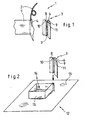
- the device 1 as illustrated in FIG. figure 1 , comprises a lace 2 and a smooth 3.
- the lace 2 is disposed inside a sheath 4 made of fabric which is part of a fabric 5.
- the lace 2 can be chosen from all types of laces, and preferably from elastic laces. Sandow®-type elastic laces can be used.
- the arm 3 is of elongate shape and comprises a cylinder 6 arranged along the rail 3.
- the cylinder 6 is intended to receive the lace 2 disposed in the sheath 4.
- the cylinder 6 is of substantially trapezoidal section, the trapezoid angles being rounded. It is further provided with a longitudinal groove 7, which merges with the small base of the trapezium, and which makes it possible to introduce the sleeve 4.
- the groove 7 is advantageously of width less than the width of the sleeve 4, which allows a good maintenance of the sleeve in the smooth 3.
- the cylinder 6 is secured to two large wings 8, 9 orthogonal via two small parallel wings 10, 11.
- the smooth 3 may be made of any material, including aluminum or plastic.
- the figure 2 illustrates an example of use of the device 1. This is the case of a false ceiling 12 with stretched fabric 13 in which a rectangular recess 14 has been made. Of course, it may be used to provide a lamp, or a ventilation system, or any other apparatus that it is desired to emerge from the false ceiling 12.
- the cover 15 is a cloth belt arranged vertically from on all four sides of the rectangle.
- the belt 15 is advantageously a single strip of fabric on which four equal distances have been fixed. canvas sleeves 4, as described in figure 1 . We then have a lace 2 in each sheath 4, then insert, at each corner of the rectangle, each sheath 4 containing the lace 2 in a smooth 3 in accordance with the figure 1 . For simplicity, only one fabric tensioning device has been represented out of the four used.
- Each arm 3 is fixed using fastening means, not shown, and which may for example be connected to the walls and / or the ceiling of the room.
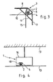
- the figure 3 illustrates a top view of an angle of the cache.
- the tensioning device 1 ensures the tension of the fabric 15 by means of the sheath 4 which contains the lace 2, the sheath 4-shoelace 2 being trapped in the cylinder 6 of the arm 3.
- the fabric tensioning device 1 ensures a cloth continuity 15 at the corners and airtightness and dust.
- the cover is also easy to assemble and has a particularly attractive appearance.
- the device 1 makes it possible to support a false stretched canvas ceiling 13.
- the principle is the same as explained above: the fabric 13 is provided with a sleeve 4 into which a lace 2 is inserted, and then the sleeve sheath 4-lace 2 is disposed in a cavity 18 of a smooth 16.
- the cavity 18 is for example identical to the cylinder 6 mentioned in the figure 1 .
- the arm 16 is also attached to a ceiling 17.
- This support of a false wall can in particular be applied to structures of circular shapes, or partially circular, as illustrated in FIG. figure 5 .
- the fabric 5 is stretched between two hooking rails 19, 20 in the shape of a circular arc.
- the rails 19, 20 may example be the smooth described in the patent FR 2 630 476 .
- the fabric 5 is provided in the middle of the fabric, or at any other desired location, with a sheath, not shown, which extends parallel to the two 19, 20.
- a sheath not shown, which extends parallel to the two 19, 20.
- a cord is placed, and the cord sheath assembly is inserted into a stringer 3 as illustrated in FIG. figure 1 , the beam 3 having the same shape in an arc of circle as the two fixing rails 19, 20.
- the fabric 5 is thus perfectly stretched between the two smooth 19, 20. It does not sag and the assembly formed by the fabric 5 and the smooth 3, 19, 20 is particularly aesthetic appearance.
Landscapes
- Engineering & Computer Science (AREA)
- Architecture (AREA)
- Physics & Mathematics (AREA)
- Electromagnetism (AREA)
- Civil Engineering (AREA)
- Structural Engineering (AREA)
- Braiding, Manufacturing Of Bobbin-Net Or Lace, And Manufacturing Of Nets By Knotting (AREA)
- Curtains And Furnishings For Windows Or Doors (AREA)
Description
- La présente invention concerne un faux plafond du type à toile tendue et son dispositif de tension de toile.
- Les faux plafonds comprennent classiquement une ou plusieurs lisses d'accrochage qui sont fixées sur chacun des murs d'une pièce, et d'une toile élastique, par exemple en polychlorure de vinyle (PVC), qui est déformée par tension afin que ses bords, pourvus de moyens d'accrochage, puissent venir se fixer aux lisses à l'aide de ces moyens d'accrochage.
- Une des principales difficultés rencontrée dans la technique de mise en place de ces faux plafonds est que cette toile, pour offrir un bel aspect, doit être fortement tendue sur les lisses. Or, les faux plafonds sont généralement disposés dans des pièces de surfaces relativement importantes, ce qui impose d'exercer sur chacun des côtés de la toile des forces de tension importantes.
- Une autre difficulté se pose lorsque l'on pratique une ouverture dans le faux plafond, par exemple pour y disposer une lampe, ou un système de ventilation, et que l'on souhaite créer au-dessus du faux plafond un cache avec des bandes de toile verticales, afin de masquer la partie comprise au-dessus du faux plafond aux personnes situées sous l'ouverture.
- Il est connu de relier ces bandes de toiles entre elles à l'aide de lisses. Ainsi, dans le cas d'une ouverture rectangulaire, chaque extrémité des quatre bandes de toile est fixée à une lisse. Il existe alors une discontinuité aux angles du cache, ce qui entraîne des problèmes d'étanchéité à l'air et à la poussière, et ce qui est peu esthétique. Par ailleurs, la fixation des quatre bandes de toile aux lisses est longue et difficile.
FR-A-2561690 - La présente invention propose une fausse paroi du type à toile tendue, et notamment pour faux-plafond et un dispositif de tension d'une toile, et notamment pour faux-plafond, permettant de remédier à ces inconvénients.
- En particulier, l'invention permet de tendre facilement et rapidement une toile pour fausse paroi, et ceci de manière étanche et esthétique dans le cas de réalisations impliquant des angles.
- Le dispositif selon l'invention permet également de soutenir une fausse paroi à n'importe quel endroit souhaité, et ceci de manière simple et rapide.
- L'invention a ainsi pour objet un faux-plafond du type à toile tendue, comprenant au moins un évidement polygonal réalisé dans la toile, remarquable en ce que chaque côté de l'évidemment est prolongé vers le haut par une bande de toile de façon à former une ceinture polygonale de toile au-dessus de l'évidemment, la ou les bandes de toile étant tendues à l'aide d'au moins un dispositif comprenant un lacet apte à être entouré, au moins partiellement, par une portion de la ou des bandes de toile et une lisse munie de moyens de préhension de l'ensemble constitué par la portion de la ou des bandes de toile et du lacet.
- La lisse est avantageusement de forme allongée et les moyens de préhension comprennent de préférence un cylindre disposé le long de la lisse et destiné à accueillir le lacet dans le sens de la longueur, ledit cylindre étant muni d'une rainure longitudinale de largeur suffisamment faible pour retenir le lacet lorsqu'il est enchâssé dans le cylindre, et de préférence inférieure à la largeur du lacet entouré par la portion de toile.
- De préférence, afin d'augmenter la préhension de l'ensemble constitué par la portion de toile et le lacet, la largeur de la rainure longitudinale est inférieure à la largeur du lacet.
- L'Homme du Métier pourra déterminer la largeur de la rainure en fonction de la taille et de la nature du cordon ainsi que la tension de toile souhaitée.
- Selon une variante de l'invention, le lacet est entouré complètement par la portion de toile. Ainsi, la portion de toile est de préférence un fourreau, ou une gaine ou une ganse, apte à envelopper le lacet. Le fourreau peut ainsi être collé, cousu ou fixé par tout autre moyen à la zone de la toile que l'on souhaite relier à la lisse.
- L'évidement peut notamment être rectangulaire.
- La ceinture est constituée par plusieurs bandes de toile, ou de préférence par une seule bande de toile, qui est maintenue aux angles du polygone à l'aide du cordon et de la lisse décrits ci-dessus.
- D'autres buts, caractéristiques et avantages de l'invention ressortiront à la lecture de la description suivante, donnée uniquement à titre d'exemple, et faite en référence aux dessins annexés, sur lesquels :
- la
figure 1 illustre les différents éléments d'un dispositif selon l'invention, - la
figure 2 illustre un faux plafond comprenant un évidement surmonté d'un cache en toile tendue à l'aide du dispositif, - la
figure 3 illustre une vue de détail d'une partie du faux plafond, - la
figure 4 illustre une partie d'un faux plafond soutenu à l'aide d'un dispositif selon l'invention, et - la
figure 5 illustre une fausse paroi soutenue par un dispositif selon l'invention en forme d'arc de cercle. - Le dispositif 1 selon l'invention, tel qu'illustré à la
figure 1 , comprend un lacet 2 et une lisse 3. Le lacet 2 est disposé à l'intérieur d'un fourreau 4 en toile qui fait partie d'une toile 5. - Le lacet 2 peut être choisi parmi tous types de lacets, et de préférence parmi les lacets élastiques. On peut notamment employer les lacets élastiques de type Sandow®.
- La lisse 3 est de forme allongée et comprend un cylindre 6 disposé le long de la lisse 3. Le cylindre 6 est destiné à accueillir le lacet 2 disposé dans le fourreau 4. Le cylindre 6 est de section sensiblement trapézoïdale, les angles du trapèze étant arrondis. Il est en outre muni d'une rainure longitudinale 7, qui se confond avec la petite base du trapèze, et qui permet d'introduire le fourreau 4. La rainure 7 est avantageusement de largeur inférieure à la largeur du fourreau 4, ce qui permet un bon maintien du fourreau dans la lisse 3. Le cylindre 6 est solidaire de deux grandes ailes 8, 9 orthogonales par l'intermédiaire de deux petites ailes parallèles 10, 11.
- La lisse 3 peut être réalisée en tout matériau, et notamment en aluminium ou en matière plastique.
- La
figure 2 , sur laquelle les éléments identiques portent les mêmes références, illustre un exemple d'utilisation du dispositif 1. Il s'agit du cas d'un faux-plafond 12 à toile tendue 13 dans lequel on a réalisé un évidement rectangulaire 14. L'évidemment 14 peut notamment servir à disposer une lampe, ou un système de ventilation, ou tout autre appareillage que l'on souhaite faire émerger du faux plafond 12. - Afin de masquer la partie située au-dessus de l'évidemment 14 pour les personnes situées sous le faux plafond 12, on dispose un cache 15 au-dessus de l'évidemment 14. Le cache 15 est une ceinture en toile disposée verticalement à partir des quatre côtés du rectangle.
- La ceinture 15 est avantageusement une unique bande de toile sur laquelle on a fixé, à égales distances, quatre fourreaux de toile 4, tel que décrit à la
figure 1 . On dispose ensuite un lacet 2 dans chaque fourreau 4, puis on insère, à chaque angle du rectangle, chaque fourreau 4 contenant le lacet 2 dans une lisse 3 conforme à lafigure 1 . Pour simplifier, on n'a représenté qu'un seul dispositif de tension de toile sur les quatre utilisés. - Chaque lisse 3 est fixée à l'aide de moyens de fixation, non représentés, et qui peuvent par exemple être reliés aux parois et/ou au plafond de la pièce.
- La
figure 3 , sur laquelle les éléments identiques à ceux de lafigure 1 portent les mêmes références, illustre une vue de dessus d'un angle du cache. Le dispositif 1 de tension assure la tension de la toile 15 à l'aide du fourreau 4 qui contient le lacet 2, l'ensemble fourreau 4-lacet 2 étant emprisonné dans le cylindre 6 de la lisse 3. - Ainsi, le dispositif 1 de tension de toile selon l'invention assure une continuité de toile 15 aux angles et une étanchéité à l'air et à la poussière. Le cache est en outre facile à monter et il est d'aspect particulièrement esthétique.
- Selon un autre mode de réalisation illustré à la
figure 4 , le dispositif 1 selon l'invention permet de soutenir un faux plafond à toile tendue 13. Le principe est le même qu'exposé ci-dessus : la toile 13 est munie d'un fourreau 4 dans lequel on insère un lacet 2, puis l'ensemble fourreau 4- lacet 2 est disposé dans une cavité 18 d'une lisse 16. La cavité 18 est par exemple identique au cylindre 6 mentionné à lafigure 1 . La lisse 16 est en outre fixée à un plafond 17. - Ce soutien d'une fausse paroi peut notamment s'appliquer à des structures de formes circulaires, ou partiellement circulaires, tel qu'illustré à la
figure 5 . La toile 5 est tendue entre deux lisses d'accrochage 19, 20 en forme d'arc de cercle. Les lisses 19, 20 peuvent par exemple être les lisses décrites dans le brevetFR 2 630 476 - Pour éviter que la toile 5 ne s'affaisse entre les deux lisses 19, 20, la toile 5 est munie en milieu de toile, ou à tout autre endroit souhaité, d'un fourreau, non représenté, qui s'étend parallèlement aux deux lisses 19, 20. On dispose dans le fourreau, comme décrit ci-dessus, un cordon, et on insère l'ensemble fourreau cordon dans une lisse 3 telle qu'illustrée à la
figure 1 , la lisse 3 présentant la même forme en arc de cercle que les deux lisses de fixation 19, 20. - La toile 5 est ainsi parfaitement tendue entre les deux lisses 19, 20. Elle ne s'affaisse pas et l'ensemble formé par la toile 5 et les lisses 3, 19, 20 est d'aspect particulièrement esthétique.
Claims (4)
- Faux-plafond (12) du type à toile (13) tendue, comprenant au moins un évidement polygonal (14) réalisé dans la toile (13), caractérisé en ce que chaque côté de l'évidemment (14) est prolongé vers le haut par une bande de toile (15) de façon à former une ceinture polygonale de toile (15) au-dessus de l'évidemment (14), la ou les bandes de toile (15) étant tendues à l'aide d'au moins un dispositif (1) comprenant un lacet (2) apte à être entouré, au moins partiellement, par une portion (4) de la ou des bandes de toile (15) et une lisse (13) munie de moyens de préhension (6) de l'ensemble constitué par la portion (4) de la ou des bandes de toile (15) et du lacet (2).
- Faux-plafond (12) selon la revendication 1, caractérisé en ce que la lisse (3) est de forme allongée et en ce que les moyens de préhension (6) comprennent un cylindre (6) disposé le long de la lisse (3) et destiné à accueillir le lacet (2) dans le sens de la longueur, ledit cylindre (6) étant muni d'une rainure longitudinale (7) de largeur inférieure à la largeur du lacet (2) entouré par la portion (4) de la ou des bandes de toile (15).
- Faux-plafond (12) selon la revendication 1 ou 2, caractérisé en ce que ladite portion (4) de la ou des bandes de toile (15) est un fourreau (4) apte à envelopper le lacet (2).
- Faux-plafond (12) selon l'une quelconque des revendications 1 à 3, caractérisé en ce que l'évidemment (14) est rectangulaire.
Applications Claiming Priority (1)
| Application Number | Priority Date | Filing Date | Title |
|---|---|---|---|
| FR0707869A FR2923506B1 (fr) | 2007-11-09 | 2007-11-09 | Dispositif de tension d'une toile pour fausse paroi et procede le mettant en oeuvre |
Publications (2)
| Publication Number | Publication Date |
|---|---|
| EP2058450A1 EP2058450A1 (fr) | 2009-05-13 |
| EP2058450B1 true EP2058450B1 (fr) | 2013-01-02 |
Family
ID=39540508
Family Applications (1)
| Application Number | Title | Priority Date | Filing Date |
|---|---|---|---|
| EP20080291052 Active EP2058450B1 (fr) | 2007-11-09 | 2008-11-10 | Dispositif de tension d'une toile pour faux plafond |
Country Status (2)
| Country | Link |
|---|---|
| EP (1) | EP2058450B1 (fr) |
| FR (1) | FR2923506B1 (fr) |
Family Cites Families (6)
| Publication number | Priority date | Publication date | Assignee | Title |
|---|---|---|---|---|
| FR1294901A (fr) * | 1961-04-19 | 1962-06-01 | Sous-plafond translucide | |
| FR2561690B1 (fr) * | 1984-03-21 | 1987-07-10 | Chenel Guy | Element de faux plafond |
| FR2630476B1 (fr) | 1988-04-22 | 1990-08-24 | Scherrer Fernand | Faux-plafond constitue par une nappe tendue accrochee, le long de ses bords, a un support fixe aux murs d'une piece d'un batiment |
| FR2715422A1 (fr) * | 1994-01-25 | 1995-07-28 | Joetzjer Andre | Système de variations de plans & volumes pour surface tendue élastique. |
| CA2190796C (fr) * | 1995-11-22 | 2002-07-02 | Wendell B. Colson | Materiau de plafond |
| FR2842227B1 (fr) * | 2002-07-09 | 2004-09-24 | Jean Paul Scherrer | Dispositif d'acces au volume interne d'un faux-plafond |
-
2007
- 2007-11-09 FR FR0707869A patent/FR2923506B1/fr active Active
-
2008
- 2008-11-10 EP EP20080291052 patent/EP2058450B1/fr active Active
Also Published As
| Publication number | Publication date |
|---|---|
| EP2058450A1 (fr) | 2009-05-13 |
| FR2923506A1 (fr) | 2009-05-15 |
| FR2923506B1 (fr) | 2016-09-09 |
Similar Documents
| Publication | Publication Date | Title |
|---|---|---|
| EP0588734B1 (fr) | Barre de seuil à montage simple | |
| EP2977518B1 (fr) | Lisse lumineuse pour fausse-paroi à toile tendue et fausse-paroi comprenant une telle lisse | |
| FR2998316A1 (fr) | Lisse eclairee pour une fausse paroi tendue, et fausse paroi tendue equipee d'une telle lisse | |
| FR2729068A1 (fr) | Dispositif de suspension de rideau de fenetre | |
| CA2768937C (fr) | Lisse a double enclenchement | |
| CA2556512C (fr) | Fausses parois en toile tendue reunies par une lisse separateur inclinee | |
| FR2627207A1 (fr) | Dispositif et outil de montage de plafonds tendus | |
| FR2970011A1 (fr) | Dispositif lumineux destine a etre integre a une fausse paroi et permettant d'obtenir un effet esthetique en trois dimensions | |
| FR3025233A1 (fr) | Lisse tubulaire lumineuse pour structure tridimensionnelle et structure tridimensionnelle en toile tendue comprenant une telle lisse | |
| WO2008113915A2 (fr) | Systeme de fixation de fausse paroi non parfaitement tendue | |
| WO2019115918A1 (fr) | Lisse a parties detachables | |
| EP2058450A1 (fr) | Dispositif de tension d'une toile pour faux plafond | |
| FR2699613A1 (fr) | Accessoire de maintien provisoire à faible distance d'une feuille souple à tendre entre deux supports. | |
| FR3103837A1 (fr) | Profilé de cadre pour la réalisation d’une fausse-paroi à toiles tendues offrant une fixation invisible des toiles et fausse-paroi réalisée avec un tel profilé de cadre | |
| WO2015036696A1 (fr) | Systeme de fixation pour la realisation de revetements tendus | |
| EP2610414B1 (fr) | Lisse corniche | |
| FR2685036A1 (fr) | Dispositif de jonction invisible, notamment pour toiles tendues. | |
| EP1494875B1 (fr) | Dispositif destine a assurer la tension et le libre acces a la face verso d'une toile tendue | |
| EP0034148A1 (fr) | Dispositif de fixation d'une feuille de revetement contre une paroi ou similaire | |
| FR2625666A1 (fr) | Ecran paravent | |
| EP3762918B1 (fr) | Procede de montage d'un revetement souple tendu sur un cadre de fixation et cadre de fixation pour la mise en oeuvre dudit procede | |
| FR2968331A1 (fr) | Abri pour bassin d'agrement et profile adapte | |
| FR2765181A1 (fr) | Embase de support d'accessoires sur la paroi souple d'un corps gonflable et embarcation pneumatique ainsi equipee | |
| EP0137086B1 (fr) | Dispositif de montage d'un faux plafond constitué d'une nappe tendue horizontalement | |
| FR2649433A1 (fr) | Baguette de fixation pour tenture murale |
Legal Events
| Date | Code | Title | Description |
|---|---|---|---|
| PUAI | Public reference made under article 153(3) epc to a published international application that has entered the european phase |
Free format text: ORIGINAL CODE: 0009012 |
|
| AK | Designated contracting states |
Kind code of ref document: A1 Designated state(s): AT BE BG CH CY CZ DE DK EE ES FI FR GB GR HR HU IE IS IT LI LT LU LV MC MT NL NO PL PT RO SE SI SK TR |
|
| AX | Request for extension of the european patent |
Extension state: AL BA MK RS |
|
| 17P | Request for examination filed |
Effective date: 20091106 |
|
| AKX | Designation fees paid |
Designated state(s): AT BE BG CH CY CZ DE DK EE ES FI FR GB GR HR HU IE IS IT LI LT LU LV MC MT NL NO PL PT RO SE SI SK TR |
|
| GRAP | Despatch of communication of intention to grant a patent |
Free format text: ORIGINAL CODE: EPIDOSNIGR1 |
|
| GRAS | Grant fee paid |
Free format text: ORIGINAL CODE: EPIDOSNIGR3 |
|
| GRAA | (expected) grant |
Free format text: ORIGINAL CODE: 0009210 |
|
| AK | Designated contracting states |
Kind code of ref document: B1 Designated state(s): AT BE BG CH CY CZ DE DK EE ES FI FR GB GR HR HU IE IS IT LI LT LU LV MC MT NL NO PL PT RO SE SI SK TR |
|
| REG | Reference to a national code |
Ref country code: GB Ref legal event code: FG4D Free format text: NOT ENGLISH |
|
| REG | Reference to a national code |
Ref country code: CH Ref legal event code: EP Ref country code: AT Ref legal event code: REF Ref document number: 591725 Country of ref document: AT Kind code of ref document: T Effective date: 20130115 |
|
| REG | Reference to a national code |
Ref country code: IE Ref legal event code: FG4D Free format text: LANGUAGE OF EP DOCUMENT: FRENCH |
|
| REG | Reference to a national code |
Ref country code: DE Ref legal event code: R096 Ref document number: 602008021324 Country of ref document: DE Effective date: 20130228 |
|
| REG | Reference to a national code |
Ref country code: AT Ref legal event code: MK05 Ref document number: 591725 Country of ref document: AT Kind code of ref document: T Effective date: 20130102 |
|
| REG | Reference to a national code |
Ref country code: NL Ref legal event code: VDEP Effective date: 20130102 |
|
| PG25 | Lapsed in a contracting state [announced via postgrant information from national office to epo] |
Ref country code: SI Free format text: LAPSE BECAUSE OF FAILURE TO SUBMIT A TRANSLATION OF THE DESCRIPTION OR TO PAY THE FEE WITHIN THE PRESCRIBED TIME-LIMIT Effective date: 20130102 |
|
| REG | Reference to a national code |
Ref country code: LT Ref legal event code: MG4D |
|
| PG25 | Lapsed in a contracting state [announced via postgrant information from national office to epo] |
Ref country code: CZ Free format text: LAPSE BECAUSE OF FAILURE TO SUBMIT A TRANSLATION OF THE DESCRIPTION OR TO PAY THE FEE WITHIN THE PRESCRIBED TIME-LIMIT Effective date: 20130102 Ref country code: NO Free format text: LAPSE BECAUSE OF FAILURE TO SUBMIT A TRANSLATION OF THE DESCRIPTION OR TO PAY THE FEE WITHIN THE PRESCRIBED TIME-LIMIT Effective date: 20130402 Ref country code: LT Free format text: LAPSE BECAUSE OF FAILURE TO SUBMIT A TRANSLATION OF THE DESCRIPTION OR TO PAY THE FEE WITHIN THE PRESCRIBED TIME-LIMIT Effective date: 20130102 Ref country code: AT Free format text: LAPSE BECAUSE OF FAILURE TO SUBMIT A TRANSLATION OF THE DESCRIPTION OR TO PAY THE FEE WITHIN THE PRESCRIBED TIME-LIMIT Effective date: 20130102 Ref country code: BG Free format text: LAPSE BECAUSE OF FAILURE TO SUBMIT A TRANSLATION OF THE DESCRIPTION OR TO PAY THE FEE WITHIN THE PRESCRIBED TIME-LIMIT Effective date: 20130402 Ref country code: IS Free format text: LAPSE BECAUSE OF FAILURE TO SUBMIT A TRANSLATION OF THE DESCRIPTION OR TO PAY THE FEE WITHIN THE PRESCRIBED TIME-LIMIT Effective date: 20130502 Ref country code: ES Free format text: LAPSE BECAUSE OF FAILURE TO SUBMIT A TRANSLATION OF THE DESCRIPTION OR TO PAY THE FEE WITHIN THE PRESCRIBED TIME-LIMIT Effective date: 20130413 Ref country code: SE Free format text: LAPSE BECAUSE OF FAILURE TO SUBMIT A TRANSLATION OF THE DESCRIPTION OR TO PAY THE FEE WITHIN THE PRESCRIBED TIME-LIMIT Effective date: 20130102 |
|
| PG25 | Lapsed in a contracting state [announced via postgrant information from national office to epo] |
Ref country code: LV Free format text: LAPSE BECAUSE OF FAILURE TO SUBMIT A TRANSLATION OF THE DESCRIPTION OR TO PAY THE FEE WITHIN THE PRESCRIBED TIME-LIMIT Effective date: 20130102 Ref country code: PT Free format text: LAPSE BECAUSE OF FAILURE TO SUBMIT A TRANSLATION OF THE DESCRIPTION OR TO PAY THE FEE WITHIN THE PRESCRIBED TIME-LIMIT Effective date: 20130502 Ref country code: PL Free format text: LAPSE BECAUSE OF FAILURE TO SUBMIT A TRANSLATION OF THE DESCRIPTION OR TO PAY THE FEE WITHIN THE PRESCRIBED TIME-LIMIT Effective date: 20130102 Ref country code: GR Free format text: LAPSE BECAUSE OF FAILURE TO SUBMIT A TRANSLATION OF THE DESCRIPTION OR TO PAY THE FEE WITHIN THE PRESCRIBED TIME-LIMIT Effective date: 20130403 Ref country code: NL Free format text: LAPSE BECAUSE OF FAILURE TO SUBMIT A TRANSLATION OF THE DESCRIPTION OR TO PAY THE FEE WITHIN THE PRESCRIBED TIME-LIMIT Effective date: 20130102 Ref country code: FI Free format text: LAPSE BECAUSE OF FAILURE TO SUBMIT A TRANSLATION OF THE DESCRIPTION OR TO PAY THE FEE WITHIN THE PRESCRIBED TIME-LIMIT Effective date: 20130102 |
|
| PG25 | Lapsed in a contracting state [announced via postgrant information from national office to epo] |
Ref country code: HR Free format text: LAPSE BECAUSE OF FAILURE TO SUBMIT A TRANSLATION OF THE DESCRIPTION OR TO PAY THE FEE WITHIN THE PRESCRIBED TIME-LIMIT Effective date: 20130102 |
|
| PG25 | Lapsed in a contracting state [announced via postgrant information from national office to epo] |
Ref country code: EE Free format text: LAPSE BECAUSE OF FAILURE TO SUBMIT A TRANSLATION OF THE DESCRIPTION OR TO PAY THE FEE WITHIN THE PRESCRIBED TIME-LIMIT Effective date: 20130102 Ref country code: SK Free format text: LAPSE BECAUSE OF FAILURE TO SUBMIT A TRANSLATION OF THE DESCRIPTION OR TO PAY THE FEE WITHIN THE PRESCRIBED TIME-LIMIT Effective date: 20130102 Ref country code: DK Free format text: LAPSE BECAUSE OF FAILURE TO SUBMIT A TRANSLATION OF THE DESCRIPTION OR TO PAY THE FEE WITHIN THE PRESCRIBED TIME-LIMIT Effective date: 20130102 Ref country code: RO Free format text: LAPSE BECAUSE OF FAILURE TO SUBMIT A TRANSLATION OF THE DESCRIPTION OR TO PAY THE FEE WITHIN THE PRESCRIBED TIME-LIMIT Effective date: 20130102 |
|
| PLBE | No opposition filed within time limit |
Free format text: ORIGINAL CODE: 0009261 |
|
| STAA | Information on the status of an ep patent application or granted ep patent |
Free format text: STATUS: NO OPPOSITION FILED WITHIN TIME LIMIT |
|
| PG25 | Lapsed in a contracting state [announced via postgrant information from national office to epo] |
Ref country code: CY Free format text: LAPSE BECAUSE OF FAILURE TO SUBMIT A TRANSLATION OF THE DESCRIPTION OR TO PAY THE FEE WITHIN THE PRESCRIBED TIME-LIMIT Effective date: 20130102 |
|
| 26N | No opposition filed |
Effective date: 20131003 |
|
| PG25 | Lapsed in a contracting state [announced via postgrant information from national office to epo] |
Ref country code: IT Free format text: LAPSE BECAUSE OF FAILURE TO SUBMIT A TRANSLATION OF THE DESCRIPTION OR TO PAY THE FEE WITHIN THE PRESCRIBED TIME-LIMIT Effective date: 20130102 |
|
| REG | Reference to a national code |
Ref country code: DE Ref legal event code: R097 Ref document number: 602008021324 Country of ref document: DE Effective date: 20131003 |
|
| BERE | Be: lapsed |
Owner name: NORMALU Effective date: 20131130 |
|
| REG | Reference to a national code |
Ref country code: CH Ref legal event code: PL |
|
| GBPC | Gb: european patent ceased through non-payment of renewal fee |
Effective date: 20131110 |
|
| PG25 | Lapsed in a contracting state [announced via postgrant information from national office to epo] |
Ref country code: MC Free format text: LAPSE BECAUSE OF FAILURE TO SUBMIT A TRANSLATION OF THE DESCRIPTION OR TO PAY THE FEE WITHIN THE PRESCRIBED TIME-LIMIT Effective date: 20130102 Ref country code: LI Free format text: LAPSE BECAUSE OF NON-PAYMENT OF DUE FEES Effective date: 20131130 Ref country code: CH Free format text: LAPSE BECAUSE OF NON-PAYMENT OF DUE FEES Effective date: 20131130 |
|
| REG | Reference to a national code |
Ref country code: IE Ref legal event code: MM4A |
|
| PG25 | Lapsed in a contracting state [announced via postgrant information from national office to epo] |
Ref country code: DE Free format text: LAPSE BECAUSE OF NON-PAYMENT OF DUE FEES Effective date: 20140603 |
|
| REG | Reference to a national code |
Ref country code: DE Ref legal event code: R119 Ref document number: 602008021324 Country of ref document: DE Effective date: 20140603 |
|
| PG25 | Lapsed in a contracting state [announced via postgrant information from national office to epo] |
Ref country code: BE Free format text: LAPSE BECAUSE OF NON-PAYMENT OF DUE FEES Effective date: 20131130 |
|
| PG25 | Lapsed in a contracting state [announced via postgrant information from national office to epo] |
Ref country code: IE Free format text: LAPSE BECAUSE OF NON-PAYMENT OF DUE FEES Effective date: 20131110 |
|
| PG25 | Lapsed in a contracting state [announced via postgrant information from national office to epo] |
Ref country code: GB Free format text: LAPSE BECAUSE OF NON-PAYMENT OF DUE FEES Effective date: 20131110 |
|
| PG25 | Lapsed in a contracting state [announced via postgrant information from national office to epo] |
Ref country code: TR Free format text: LAPSE BECAUSE OF FAILURE TO SUBMIT A TRANSLATION OF THE DESCRIPTION OR TO PAY THE FEE WITHIN THE PRESCRIBED TIME-LIMIT Effective date: 20130102 |
|
| PG25 | Lapsed in a contracting state [announced via postgrant information from national office to epo] |
Ref country code: HU Free format text: LAPSE BECAUSE OF FAILURE TO SUBMIT A TRANSLATION OF THE DESCRIPTION OR TO PAY THE FEE WITHIN THE PRESCRIBED TIME-LIMIT; INVALID AB INITIO Effective date: 20081110 Ref country code: LU Free format text: LAPSE BECAUSE OF NON-PAYMENT OF DUE FEES Effective date: 20131110 |
|
| PG25 | Lapsed in a contracting state [announced via postgrant information from national office to epo] |
Ref country code: MT Free format text: LAPSE BECAUSE OF FAILURE TO SUBMIT A TRANSLATION OF THE DESCRIPTION OR TO PAY THE FEE WITHIN THE PRESCRIBED TIME-LIMIT Effective date: 20130102 |
|
| REG | Reference to a national code |
Ref country code: FR Ref legal event code: PLFP Year of fee payment: 8 |
|
| REG | Reference to a national code |
Ref country code: FR Ref legal event code: PLFP Year of fee payment: 9 |
|
| REG | Reference to a national code |
Ref country code: FR Ref legal event code: PLFP Year of fee payment: 10 |
|
| REG | Reference to a national code |
Ref country code: FR Ref legal event code: PLFP Year of fee payment: 11 |
|
| PGFP | Annual fee paid to national office [announced via postgrant information from national office to epo] |
Ref country code: FR Payment date: 20250423 Year of fee payment: 17 |