EP2058090A2 - Manipulator apparatus and medical device system - Google Patents
Manipulator apparatus and medical device system Download PDFInfo
- Publication number
- EP2058090A2 EP2058090A2 EP08018811A EP08018811A EP2058090A2 EP 2058090 A2 EP2058090 A2 EP 2058090A2 EP 08018811 A EP08018811 A EP 08018811A EP 08018811 A EP08018811 A EP 08018811A EP 2058090 A2 EP2058090 A2 EP 2058090A2
- Authority
- EP
- European Patent Office
- Prior art keywords
- joint
- manipulator
- trajectory
- joints
- attitude
- Prior art date
- Legal status (The legal status is an assumption and is not a legal conclusion. Google has not performed a legal analysis and makes no representation as to the accuracy of the status listed.)
- Granted
Links
- 238000011282 treatment Methods 0.000 description 19
- 238000000034 method Methods 0.000 description 5
- 238000010586 diagram Methods 0.000 description 4
- 238000002674 endoscopic surgery Methods 0.000 description 4
- 238000003780 insertion Methods 0.000 description 3
- 230000037431 insertion Effects 0.000 description 3
- 230000008407 joint function Effects 0.000 description 2
- 238000001356 surgical procedure Methods 0.000 description 2
- 239000013598 vector Substances 0.000 description 2
- 238000005452 bending Methods 0.000 description 1
- 230000008859 change Effects 0.000 description 1
- 238000002192 cholecystectomy Methods 0.000 description 1
- 238000013329 compounding Methods 0.000 description 1
- 230000001419 dependent effect Effects 0.000 description 1
- 238000002224 dissection Methods 0.000 description 1
- 230000006870 function Effects 0.000 description 1
- 239000012212 insulator Substances 0.000 description 1
- 210000004072 lung Anatomy 0.000 description 1
- 238000012986 modification Methods 0.000 description 1
- 230000004048 modification Effects 0.000 description 1
- 230000000704 physical effect Effects 0.000 description 1
- 230000009467 reduction Effects 0.000 description 1
- 238000002271 resection Methods 0.000 description 1
- 230000004044 response Effects 0.000 description 1
- 230000000007 visual effect Effects 0.000 description 1
Images


Classifications
-
- A—HUMAN NECESSITIES
- A61—MEDICAL OR VETERINARY SCIENCE; HYGIENE
- A61B—DIAGNOSIS; SURGERY; IDENTIFICATION
- A61B34/00—Computer-aided surgery; Manipulators or robots specially adapted for use in surgery
- A61B34/30—Surgical robots
- A61B34/37—Master-slave robots
-
- A—HUMAN NECESSITIES
- A61—MEDICAL OR VETERINARY SCIENCE; HYGIENE
- A61B—DIAGNOSIS; SURGERY; IDENTIFICATION
- A61B34/00—Computer-aided surgery; Manipulators or robots specially adapted for use in surgery
- A61B34/30—Surgical robots
-
- A—HUMAN NECESSITIES
- A61—MEDICAL OR VETERINARY SCIENCE; HYGIENE
- A61B—DIAGNOSIS; SURGERY; IDENTIFICATION
- A61B34/00—Computer-aided surgery; Manipulators or robots specially adapted for use in surgery
- A61B34/70—Manipulators specially adapted for use in surgery
- A61B34/71—Manipulators operated by drive cable mechanisms
-
- B—PERFORMING OPERATIONS; TRANSPORTING
- B25—HAND TOOLS; PORTABLE POWER-DRIVEN TOOLS; MANIPULATORS
- B25J—MANIPULATORS; CHAMBERS PROVIDED WITH MANIPULATION DEVICES
- B25J9/00—Programme-controlled manipulators
- B25J9/16—Programme controls
- B25J9/1628—Programme controls characterised by the control loop
- B25J9/1633—Programme controls characterised by the control loop compliant, force, torque control, e.g. combined with position control
-
- B—PERFORMING OPERATIONS; TRANSPORTING
- B25—HAND TOOLS; PORTABLE POWER-DRIVEN TOOLS; MANIPULATORS
- B25J—MANIPULATORS; CHAMBERS PROVIDED WITH MANIPULATION DEVICES
- B25J9/00—Programme-controlled manipulators
- B25J9/16—Programme controls
- B25J9/1628—Programme controls characterised by the control loop
- B25J9/1643—Programme controls characterised by the control loop redundant control
-
- A—HUMAN NECESSITIES
- A61—MEDICAL OR VETERINARY SCIENCE; HYGIENE
- A61B—DIAGNOSIS; SURGERY; IDENTIFICATION
- A61B17/00—Surgical instruments, devices or methods, e.g. tourniquets
- A61B17/00234—Surgical instruments, devices or methods, e.g. tourniquets for minimally invasive surgery
- A61B2017/00292—Surgical instruments, devices or methods, e.g. tourniquets for minimally invasive surgery mounted on or guided by flexible, e.g. catheter-like, means
- A61B2017/003—Steerable
- A61B2017/00305—Constructional details of the flexible means
- A61B2017/00314—Separate linked members
-
- A—HUMAN NECESSITIES
- A61—MEDICAL OR VETERINARY SCIENCE; HYGIENE
- A61B—DIAGNOSIS; SURGERY; IDENTIFICATION
- A61B34/00—Computer-aided surgery; Manipulators or robots specially adapted for use in surgery
- A61B34/30—Surgical robots
- A61B2034/305—Details of wrist mechanisms at distal ends of robotic arms
- A61B2034/306—Wrists with multiple vertebrae
-
- A—HUMAN NECESSITIES
- A61—MEDICAL OR VETERINARY SCIENCE; HYGIENE
- A61B—DIAGNOSIS; SURGERY; IDENTIFICATION
- A61B90/00—Instruments, implements or accessories specially adapted for surgery or diagnosis and not covered by any of the groups A61B1/00 - A61B50/00, e.g. for luxation treatment or for protecting wound edges
- A61B90/06—Measuring instruments not otherwise provided for
- A61B2090/064—Measuring instruments not otherwise provided for for measuring force, pressure or mechanical tension
-
- A—HUMAN NECESSITIES
- A61—MEDICAL OR VETERINARY SCIENCE; HYGIENE
- A61B—DIAGNOSIS; SURGERY; IDENTIFICATION
- A61B90/00—Instruments, implements or accessories specially adapted for surgery or diagnosis and not covered by any of the groups A61B1/00 - A61B50/00, e.g. for luxation treatment or for protecting wound edges
- A61B90/36—Image-producing devices or illumination devices not otherwise provided for
- A61B90/361—Image-producing devices, e.g. surgical cameras
Definitions
- the present invention relates to a manipulator apparatus and a medical device system, and in particular to a manipulator apparatus having a plurality of joints driven efficiently in a manner dependent on a target treatment and to a medical device system which includes the manipulator apparatus.
- endoscopic surgery for performing various treatments inside a body cavity has become widespread.
- the endoscopic surgery is performed by opening an insertion hole in a body wall and inserting an endoscope and treatment instruments percutaneously into a body cavity through the insertion hole.
- This type of technique does not require a large dissection and is widely applied as a minimally invasive technique for cholecystectomy or resection of a part of the lung.
- a master-slave type medical manipulator apparatus has been proposed.
- Japanese Patent Application Laid-Open Publication No. H9-66056 discloses a medical manipulator system for use in surgery in which a plurality of medical manipulator apparatuses are used and which can cope quickly if a fault of some kind occurs in one or more of the manipulator apparatuses.
- the manipulator system provides a high degree of safety and operability, and allows a reduction in operating time and in the level of invasiveness to the patient.
- inverse kinematic calculations are used to find target values for the attitude and position of manipulator distal end.
- inverse kinematic calculations are used to calculate joint angle trajectories for each joint.
- the number of joints to be driven is large, overall driving error increases due to the compounding of errors at each joint.
- Japanese Patent Application Laid-Open Publication No. H3-12709 discloses a method which makes use of fuzzy inference to calculate the joint angle trajectories which allow the target values to be reached with the minimum number of driven joints.
- a medical device system which makes use of one or more highly accurate and highly efficient miniature manipulators projecting from the distal end portion is also desired.
- the manipulator apparatus of the present invention includes a manipulator having a plurality of joints, parameter storing means for storing joint parameters, including a largest available force, of each joint of the plurality of joints; trajectory inputting means for inputting, as a trajectory plan, trajectories for moving a distal end of the manipulator from a current position and attitude to a target position and attitude; and trajectory setting means for setting a joint angle trajectory for each joint providing a largest available force from among joint angle trajectories which allow movement to the target position and attitude with a minimum number of driven joints based on a largest available force parameter for the each joint stored in the parameter storing means and the trajectory plan.
- the medical device system of the present invention includes the manipulator apparatus.
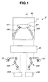
- Fig. 1 is a schematic view for explaining an outline of a medical device system 2 of an embodiment of the invention.
- a display screen of a display apparatus 60 which is display means, displays a pickup image 61 of inside a living body 10 picked up using a CCD 51, which is image pickup means, of the endoscope apparatus 50 which is described in a later section.
- the pickup image 61 includes manipulators 100 and 200, each of which has two joints, for performing treatment on a diseased portion 11 within the living body 10.
- a hand arm is provided at a distal end portion 101 of the manipulator 100, and a knife arm is provided at the distal end portion 201 of the manipulator 200.
- the operator operates the left and right master-slave apparatuses 42A and 42B using his or her left and right hands 12 and 13.
- the master-slave apparatuses 42A and 42B are trajectory inputting means 42 for inputting trajectories for moving the distal end portions 101 and 201 of the manipulators 100 and 200 to a target position and attitude from a current position and attitude.
- a manipulator control apparatus 48 drives the manipulators 100 and 200 based on trajectory information inputted by trajectory inputting means 42.
- the medical device system 2 shown in Fig. 1 has a configuration which is basically the same as that of the present embodiment whether the manipulator apparatus has two manipulators, the manipulator apparatus has a single manipulator, or three or more manipulators.
- the medical device system 2 includes degree-of-freedom selecting means 43A and 43B for selecting degrees of freedom of the manipulators and limiting non-selected degrees of freedom.
- the manipulator of the present embodiment includes a plurality of joints and has a high number of degrees of freedom, in the medical device system 2 a manipulator with a fewer degrees of freedom may offer better operability, and safer and more reliable processing for some types of treatment.
- the operator is able to limit the number of degrees of freedom of the manipulators 100 and 200 according to the treatment by using the degree-of-freedom selecting means 43A and 43B.
- the operations of the degree-of-freedom selecting means 43 of are described in a later section.
- Fig. 1 shows a master-slave type arrangement as the trajectory inputting means 42
- the invention is not limited to such a configuration, and another known type of inputting means which permits input of desired trajectories, such as a keyboard, a touch pen or a joystick may be used.
- Fig. 2 is an external view showing the exterior of the medical device system 2 of the present embodiment.
- the two manipulators 100 and 200 protrude from the forceps holes 57 and 58 of the distal end portion 56 of the endoscope 55.
- a CCD 51 which is image pickup means and an illuminating portion 52B which is illuminating means are provided in the distal end portion 56.
- a hand arm is provided at the distal end portion 101 of the manipulator 100 and a knife arm is provided at the distal end portion 201 of the other manipulator 200.
- the manipulator of the present embodiment is a miniature manipulator for projection from the distal end portion of the endoscope, and, with a diameter of approximately 2 mm to 5 mm, is extremely compact. Hence, the manipulator differs from the majority of known manipulators, making it difficult to execute the target treatment unless the manipulator is driven efficiently.
- Fig. 3A and Fig. 3B are drawings for explaining functions of the joints of the manipulator 200.
- Fig. 4 is an external perspective view of the manipulator 200.
- Fig. 5 is a cross-sectional view of the manipulator 200.
- Fig. 6 is a cross-sectional view for explaining the operations of the manipulator 200.
- Fig. 3A shows the joints of the manipulator 200.
- the manipulator 200 includes, in order starting with the manipulator proximal end portion 210 (coordinates: x0, y0, z0), a straight-line motion driving joint 211 (coordinates: x1, y1, z1), and a roll driving joint 212 (coordinates: x2, y2, z2) a yaw driving joint 213 (coordinates: x3, y3, z3), pitch driving joint 214 (coordinates: x4, y4, z4), yaw driving joint 215 (coordinates: x5, y5, z5) and pitch driving joint 216 (coordinates: x6, y6, z6), which are rotationally driven joints.
- the knife arm is provided at the distal end portion 201 of the manipulator 200.
- Fig. 3B shows the joints manipulator 200 in a driven state.
- the yaw driving joint 213 has introduced a bend of -3 ⁇ and the yaw driving joint 215 has introduced a bend of 5 ⁇ .
- the manipulator 200 is able to move the distal end portion 201 from a current position and attitude to a target position and attitude by adjusting the joint angles of the plurality of joints. It is to be noted that the manipulator 200 has a higher number of degrees of freedom than are required to achieve the target position and attitude. In other words, since the manipulator 200 has a higher number of degrees of freedom than is demanded by the work, a plurality of joint angle trajectories exist for moving to the target position and attitude. Moreover, the accuracy and efficiency of the manipulator apparatus 1 differ according to which joint angle trajectories are selected.
- the manipulator 200 has five joint sections 251 to 255 joined by four joints 216 to 219. Each joint is fixed using rivets 260 in two locations and allows rotation in one direction.
- the manipulator 200 has two pitch driving joints 216 and 214 and two yaw driving joints 215 and 213. Each joint is fixed at two diagonal points with ends of a pair of angle wires 270.
- the joint sections 251 to 255 can be bent at the respective joints by operations on the angle wires 270 using driving means 23 (not shown).
- the manipulator 200 has a knife arm at the distal end portion 201 thereof, and position and attitude of the knife arm are changed by driving the manipulator 200.
- Fig. 5 is a cross-sectional view of the manipulator 200 shown in Fig. 4 .
- an operation wire 272 of the knife arm is provided within a flexible tube 271 which is an insulator.
- the operation wire 272 allows high frequency electrical currents to be to be transmitted and is electrically connected to the knife arm.
- Fig. 6 shows a state in which the knife arm is housed in the manipulator 200.
- the angle wires (not shown) are pulling the pitch driving joint 216, introducing a bend at the bending section 251 at the most distal end portion of the manipulator 200.
- the manipulator apparatus 1 makes use of the angle wires to drive the manipulator 200 and can therefore have a structure which is simple, reliable and miniaturized.
- Fig. 7 is a block diagram showing a configuration of the medical device system 2 of the present embodiment.
- the following describes a medical device system 2 having a single manipulator 200.
- the basic configuration is the same when the medical device system 2 has a plurality of manipulator apparatuses 1.
- the only difference is the inclusion, in the case of the medical device system 2 having a plurality of manipulator apparatuses 1, of components for each manipulator apparatus.
- Fig. 7 shows a configuration of a medical device system 2 featuring a manipulator (not shown) having a driving portion 20 for driving the manipulator within the living body 10.
- the manipulator includes a load sensor 21, a position sensor 22 and driving means 23.
- the load sensor 21 is for detecting loads generated on each of the joints when the joints of the manipulator are driven to perform a desired operation.
- the load is expressed as torque (N/m) when a rotation driving joint is loaded and as force (N) when a straight-line motion driving joint is loaded.
- One way of detecting the load when wire driving is used is to measure the tension in the wire. Another possibility is to detect the load with a strain gage or the like. Further, when the wire is driven using a motor, the load can be detected from the power consumption of the motor. Note that a new sensor does not necessarily have to be included in the manipulator.
- the components already present in the manipulator can, in some cases, be used to output load information to load detecting means 40.
- the position sensor 22 is a sensor for detecting the position and attitude of each of the joints using a magnetic sensor or the like. Note that, like the load sensor 21, the position sensor 22 does not necessarily have to include a sensor in the manipulator. It is possible instead to detect the change in position and attitude of each joint caused by the driving means 23 using an encoder and output the resulting position information to the position calculating means 41.
- Trajectory setting means 45 sets the joint angle trajectory of each joint based on information from the position calculating means 41, the trajectory inputting means 42 and the degree-of-freedom selecting means 43 and on joint parameters inputted from parameter inputting means 44 and stored in parameter storing means 46.
- Drive controlling means 47 drives the driving means 23 of the joints of the manipulator in accordance with joint angle trajectories set by the trajectory setting means 45.
- the endoscope apparatus 50 includes image pickup means 51, which is a CCD or the like provided on a distal end portion of an insertion portion (not shown), illuminating means 52 for illuminating portions within the living body 10, an image pickup controlling portion 53 for performing processing and the like on the images picked up by the image pickup means 51, and an endoscope controlling portion 54 for controlling the entire endoscope.
- image pickup means 51 which is a CCD or the like provided on a distal end portion of an insertion portion (not shown)
- illuminating means 52 for illuminating portions within the living body 10
- an image pickup controlling portion 53 for performing processing and the like on the images picked up by the image pickup means 51
- an endoscope controlling portion 54 for controlling the entire endoscope.
- a display apparatus 60 displays the image picked up by the endoscope apparatus 50, and can be also used as a touch panel for inputting manipulator trajectories and the like.
- the load sensor 21, the load detecting means 40, the position sensor 22 and the position calculating means 41 need not be provided for all of the plurality of joints.
- the straight-line motion driving joint 211 and roll driving joint 212 may be driven by hand.
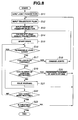
- Fig. 8 is a flow chart for explaining the flow of operations of the manipulator apparatus 1.
- the manipulator apparatus 1 receives input of joint parameters for each joint using the parameter inputting means 44, and stores the inputted parameters in the parameter storing means 46. Note that, if the joint parameters have been inputted in advance, there is no need to input parameters each time the manipulator apparatus is used.
- Joint parameters are pieces of joint information necessary for driving the joints of the manipulator.
- joint parameters may include DH parameters (initial coordinates, length, direction and the like), joint motion ranges (angle range, straight-line motion range, and the like), and joint operation accuracy (response speed and the like).
- the joint parameters in the medical device system 2 further include a largest available force parameter of the joints and a permissible load parameter for the joints.
- the largest available force of a given joint is the maximum force which can be generated by that joint and, for rotationally driven joints, may be expressed in terms of torque (N/m) or driving motor electrical power (W).
- the permissible load of a given joint is the maximum load which can be applied to that joint. If a load which exceeds the permissible load is applied to any joint, there is a risk of damage to the joint or driving wires.
- the permissible load is again expressed in terms of a torque or an electrical power value of the driving motor.
- the speed of the processing by the trajectory inputting means 42 from step S12 onwards may be increased by arranging the joint parameters stored in the parameter storing means 46 in order of available force or permissible load.
- a trajectory plan for moving the distal end of the manipulator from a current position and attitude to a target position and attitude is inputted using the trajectory inputting means 42.
- the manipulator of the present embodiment has six degrees of freedom and can therefore be freely positioned with any attitude in three-dimensional space.
- Fig. 9 is a pickup image 61 from the endoscope and shows a treatment in which a scalpel at the distal end portion 201 of the manipulator 200 dissects a diseased portion 11.
- the distal end portion 201 is preferably moved from right left to left along the straight line 11 B, as shown by the arrow A, to the position of the distal end portion 201B.
- unnecessary motion in the pitch and roll directions sometimes occurs, even if the operator was very careful when operating the master-slave apparatus (trajectory inputting means 42).
- the number of degrees of freedom in the pitch and roll directions can be limited when performing the above-described treatment using the degree-of-freedom selecting means 43.
- the roll direction degree of freedom is not generally required.
- the degree-of-freedom limiting information from the degree-of-freedom selecting means 43 is used to cancel out inputs of the limited direction to the trajectory setting means 45, which is described in a later section.
- the motion directions are expressed using vectors, to "cancel out” the input means to remove the vector component in the limited direction.
- the manipulator apparatus 1 is able to perform safer and more reliable processing.
- the trajectory setting means 45 sets the joint angle trajectories of each joint based on the joint parameters and the trajectory plan.
- the trajectory setting means 45 sets the joint angle trajectories providing the largest available force among the joint angle trajectories which allow movement to the target position and attitude with the minimum number of driven joints, based on the largest available force parameters for the joints stored in the parameter storing means 46. Note that setting the joint angle trajectories to provide largest available forces does not necessarily mean to set the joint angle trajectories by selecting the joints which generate the largest forces but mean to set such joint angle trajectories as to generate the largest forces by giving precedence to the joints capable of generating the large force when selecting the joints.
- the manipulator apparatus 1 of the present embodiment when the joint angle trajectories are set using inverse kinematic calculations, the number of joints is minimized to prioritize operation accuracy.
- the manipulator apparatus 1 of the present embodiment selects, as a secondary priority, the joint angle trajectories which provide the largest available force.
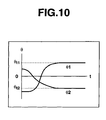
- Fig. 10 shows an example of the joint angle trajectories set by the trajectory setting means 45.
- Fig. 10 shows the joint angle trajectory of two rotationally driven joints.
- the manipulator In the miniature manipulator apparatus for medical use, accuracy is most important. However, due to its small size, the manipulator can only generate small forces and is not always capable of executing the desired treatment.
- the manipulator apparatus 1 of the present embodiment can perform safer and more reliable processing.
- the drive controlling means 47 starts to drive the driving means 23 of each joint in accordance with the joint angle trajectories set by the trajectory setting means 45.
- the load detecting means 40 calculates the load on each joint based on information from the load sensor 21.
- the trajectory setting means 45 compares the load on each joint with the permissible load parameter for each joint stored in the parameter storing means 46, and, when the load on every joint is less than the permissible load, the driving means 23 continues to drive the distal end portion of the manipulator until reaching the target position and attitude.
- the trajectory setting means 45 When, on the other hand, a load on any of the joints equals or exceeds the permissible load, the trajectory setting means 45 performs the following processing to set new joint angle trajectories.
- the trajectory setting means 45 proceeds to step S18 and changes the joints to be driven.
- the joint angle trajectories are then recalculated.
- the trajectory setting means 45 When there are no joints not currently being driven for which the permissible load parameter is larger than that of joints currently in use (No), the trajectory setting means 45 performs processing from step S 19 onwards.
- the trajectory setting means 45 proceeds to step S20 and increments the number of joints to be driven by 1. The trajectory setting means 45 then recalculates the joint angle trajectories.
- step S 19 when all of the joints are being driven (No), the trajectory setting means 45 cannot move the manipulator distal end portion to the target position and attitude along the inputted trajectories, and therefore uses the warning means 70 to issue a warning to inform the operator.
- the warning can make use of a known method such as a sound, vibration or a visual display on the display apparatus 60.
- the operator can continue the treatment by inputting a new set of new trajectories.
- the drive controlling means 47 drives the driving means 23 of each joint in accordance with the joint angle trajectories set by the trajectory setting means 45 until the manipulator distal end portion has moved to the target position and attitude.
- the manipulator apparatus 1 then continues to operate until a signal indicating the end of treatment is received in step S23.
- the manipulator apparatus 1 of the present embodiment is highly accurate because only the minimum number of joints is driven. Moreover, the manipulator apparatus 1 generates a large force despite the miniature size of the manipulator. The manipulator can therefore be driven accurately and efficiently.
- the medical device system 2 including the manipulator apparatus 1 of the present embodiment can therefore drive the treatment instrument accurately, efficiently and reliably.
Abstract
Description
- The present invention relates to a manipulator apparatus and a medical device system, and in particular to a manipulator apparatus having a plurality of joints driven efficiently in a manner dependent on a target treatment and to a medical device system which includes the manipulator apparatus.
- In recent years endoscopic surgery for performing various treatments inside a body cavity has become widespread. The endoscopic surgery is performed by opening an insertion hole in a body wall and inserting an endoscope and treatment instruments percutaneously into a body cavity through the insertion hole. This type of technique does not require a large dissection and is widely applied as a minimally invasive technique for cholecystectomy or resection of a part of the lung. To improve operability in this type of surgery, a master-slave type medical manipulator apparatus has been proposed.
- Japanese Patent Application Laid-Open Publication No.
H9-66056 - When controlling multi-joint manipulators, inverse kinematic calculations are used to find target values for the attitude and position of manipulator distal end. In other words, when a trajectory plan is provided, inverse kinematic calculations are used to calculate joint angle trajectories for each joint. When, in the calculation of joint angle trajectories, the number of joints to be driven is large, overall driving error increases due to the compounding of errors at each joint. To deal with this problem, Japanese Patent Application Laid-Open Publication No.
H3-12709 - In one type of endoscopic surgery even less invasive than conventional endoscopic surgery, treatment is performed using a medical instrument provided at a distal end portion of the endoscope. However, a treatment instrument which passes through the forceps channel of the endoscope and projects from distal end portion has poor operability, and so methods which make use of a miniature manipulator to increase the number of degrees of freedom and capabilities of the treatment instrument have been considered. Although it is difficult for such a miniature manipulator which projects from the distal end portion to have a complex structure due to size constraints, high levels of accuracy and efficiency are demanded. However, with this type of miniature manipulator apparatus, it is difficult to achieve both high accuracy and high efficiency.
- A medical device system which makes use of one or more highly accurate and highly efficient miniature manipulators projecting from the distal end portion is also desired.
- It is an object of present invention to provide a manipulator apparatus having a plurality of joints which are driven with high accuracy and high efficiency, and a medical device system equipped with the manipulator apparatus.
- To achieve the object, the manipulator apparatus of the present invention includes a manipulator having a plurality of joints, parameter storing means for storing joint parameters, including a largest available force, of each joint of the plurality of joints; trajectory inputting means for inputting, as a trajectory plan, trajectories for moving a distal end of the manipulator from a current position and attitude to a target position and attitude; and trajectory setting means for setting a joint angle trajectory for each joint providing a largest available force from among joint angle trajectories which allow movement to the target position and attitude with a minimum number of driven joints based on a largest available force parameter for the each joint stored in the parameter storing means and the trajectory plan. Further, the medical device system of the present invention includes the manipulator apparatus.
-
-
Fig. 1 is a schematic view for explaining an outline of a medical device system; -
Fig. 2 is an external view showing an exterior of the medical device system; -
Fig. 3A is a diagram for explaining joint functions of a manipulator; -
Fig. 3B is a diagram for explaining the joint functions of the manipulator; -
Fig. 4 is an external perspective view of the manipulator; -
Fig. 5 is a cross-sectional view of the manipulator; -
Fig. 6 is a cross-sectional view for explaining an operation of the manipulator; -
Fig. 7 is a block diagram of the medical device system; -
Fig. 8 is a flow chart for explaining the flow of operations of the manipulator apparatus; -
Fig. 9 is an endoscope pick up image showing a treatment using the manipulator; and -
Fig. 10 shows an example of set joint angle trajectories. - The following describes embodiments of the invention with reference to the accompanying drawings.
-
Fig. 1 is a schematic view for explaining an outline of amedical device system 2 of an embodiment of the invention. InFig. 1 , a display screen of adisplay apparatus 60, which is display means, displays apickup image 61 of inside aliving body 10 picked up using aCCD 51, which is image pickup means, of theendoscope apparatus 50 which is described in a later section. Thepickup image 61 includesmanipulators diseased portion 11 within theliving body 10. A hand arm is provided at adistal end portion 101 of themanipulator 100, and a knife arm is provided at thedistal end portion 201 of themanipulator 200. - The operator operates the left and right master-
slave apparatuses right hands slave apparatuses distal end portions manipulators manipulator control apparatus 48 drives themanipulators - Note that the
medical device system 2 shown inFig. 1 has a configuration which is basically the same as that of the present embodiment whether the manipulator apparatus has two manipulators, the manipulator apparatus has a single manipulator, or three or more manipulators. - Note also that the
medical device system 2 includes degree-of-freedom selecting means 43A and 43B for selecting degrees of freedom of the manipulators and limiting non-selected degrees of freedom. Although the manipulator of the present embodiment includes a plurality of joints and has a high number of degrees of freedom, in the medical device system 2 a manipulator with a fewer degrees of freedom may offer better operability, and safer and more reliable processing for some types of treatment. The operator is able to limit the number of degrees of freedom of themanipulators - Note that although
Fig. 1 shows a master-slave type arrangement as the trajectory inputting means 42, the invention is not limited to such a configuration, and another known type of inputting means which permits input of desired trajectories, such as a keyboard, a touch pen or a joystick may be used. -
Fig. 2 is an external view showing the exterior of themedical device system 2 of the present embodiment. InFig. 2 , the twomanipulators forceps holes distal end portion 56 of theendoscope 55. ACCD 51 which is image pickup means and anilluminating portion 52B which is illuminating means are provided in thedistal end portion 56. Further, in the same way as inFig. 1 , a hand arm is provided at thedistal end portion 101 of themanipulator 100 and a knife arm is provided at thedistal end portion 201 of theother manipulator 200. - The manipulator of the present embodiment is a miniature manipulator for projection from the distal end portion of the endoscope, and, with a diameter of approximately 2 mm to 5 mm, is extremely compact. Hence, the manipulator differs from the majority of known manipulators, making it difficult to execute the target treatment unless the manipulator is driven efficiently.
- The following describes the structure of the manipulator of the present embodiment with reference to
Fig. 3 to Fig. 6 .Fig. 3A andFig. 3B are drawings for explaining functions of the joints of themanipulator 200.Fig. 4 is an external perspective view of themanipulator 200.Fig. 5 is a cross-sectional view of themanipulator 200.Fig. 6 is a cross-sectional view for explaining the operations of themanipulator 200. -
Fig. 3A shows the joints of themanipulator 200. Themanipulator 200 includes, in order starting with the manipulator proximal end portion 210 (coordinates: x0, y0, z0), a straight-line motion driving joint 211 (coordinates: x1, y1, z1), and a roll driving joint 212 (coordinates: x2, y2, z2) a yaw driving joint 213 (coordinates: x3, y3, z3), pitch driving joint 214 (coordinates: x4, y4, z4), yaw driving joint 215 (coordinates: x5, y5, z5) and pitch driving joint 216 (coordinates: x6, y6, z6), which are rotationally driven joints. The knife arm is provided at thedistal end portion 201 of themanipulator 200. -
Fig. 3B shows thejoints manipulator 200 in a driven state. Here, the yaw driving joint 213 has introduced a bend of -3θ and the yaw driving joint 215 has introduced a bend of 5θ. - The
manipulator 200 is able to move thedistal end portion 201 from a current position and attitude to a target position and attitude by adjusting the joint angles of the plurality of joints. It is to be noted that themanipulator 200 has a higher number of degrees of freedom than are required to achieve the target position and attitude. In other words, since themanipulator 200 has a higher number of degrees of freedom than is demanded by the work, a plurality of joint angle trajectories exist for moving to the target position and attitude. Moreover, the accuracy and efficiency of themanipulator apparatus 1 differ according to which joint angle trajectories are selected. - The following describes the structure of the
manipulator 200 in detail with reference toFig. 4 andFig. 5 . As shown in the perspective view ofFig. 4 , themanipulator 200 has fivejoint sections 251 to 255 joined by fourjoints 216 to 219. Each joint is fixed usingrivets 260 in two locations and allows rotation in one direction. Thus, themanipulator 200 has twopitch driving joints yaw driving joints angle wires 270. Thejoint sections 251 to 255 can be bent at the respective joints by operations on theangle wires 270 using driving means 23 (not shown). Themanipulator 200 has a knife arm at thedistal end portion 201 thereof, and position and attitude of the knife arm are changed by driving themanipulator 200. -
Fig. 5 is a cross-sectional view of themanipulator 200 shown inFig. 4 . Within a central portion of themanipulator 200, anoperation wire 272 of the knife arm is provided within aflexible tube 271 which is an insulator. Theoperation wire 272 allows high frequency electrical currents to be to be transmitted and is electrically connected to the knife arm. -
Fig. 6 shows a state in which the knife arm is housed in themanipulator 200. In this state, the angle wires (not shown) are pulling the pitch driving joint 216, introducing a bend at thebending section 251 at the most distal end portion of themanipulator 200. - The
manipulator apparatus 1 makes use of the angle wires to drive themanipulator 200 and can therefore have a structure which is simple, reliable and miniaturized. - The following describes a configuration of the
medical device system 2 of the present embodiment with reference toFig. 7. Fig. 7 is a block diagram showing a configuration of themedical device system 2 of the present embodiment. For the sake of simplicity, the following describes amedical device system 2 having asingle manipulator 200. However, the basic configuration is the same when themedical device system 2 has a plurality ofmanipulator apparatuses 1. The only difference is the inclusion, in the case of themedical device system 2 having a plurality ofmanipulator apparatuses 1, of components for each manipulator apparatus. -
Fig. 7 shows a configuration of amedical device system 2 featuring a manipulator (not shown) having a drivingportion 20 for driving the manipulator within the livingbody 10. The manipulator includes aload sensor 21, aposition sensor 22 and driving means 23. - The
load sensor 21 is for detecting loads generated on each of the joints when the joints of the manipulator are driven to perform a desired operation. The load is expressed as torque (N/m) when a rotation driving joint is loaded and as force (N) when a straight-line motion driving joint is loaded. One way of detecting the load when wire driving is used is to measure the tension in the wire. Another possibility is to detect the load with a strain gage or the like. Further, when the wire is driven using a motor, the load can be detected from the power consumption of the motor. Note that a new sensor does not necessarily have to be included in the manipulator. The components already present in the manipulator can, in some cases, be used to output load information to load detectingmeans 40. - The
position sensor 22 is a sensor for detecting the position and attitude of each of the joints using a magnetic sensor or the like. Note that, like theload sensor 21, theposition sensor 22 does not necessarily have to include a sensor in the manipulator. It is possible instead to detect the change in position and attitude of each joint caused by the driving means 23 using an encoder and output the resulting position information to the position calculating means 41. - Trajectory setting means 45 sets the joint angle trajectory of each joint based on information from the position calculating means 41, the trajectory inputting means 42 and the degree-of-
freedom selecting means 43 and on joint parameters inputted from parameter inputting means 44 and stored in parameter storing means 46. - Drive controlling means 47 drives the driving means 23 of the joints of the manipulator in accordance with joint angle trajectories set by the trajectory setting means 45.
- The
endoscope apparatus 50 includes image pickup means 51, which is a CCD or the like provided on a distal end portion of an insertion portion (not shown), illuminating means 52 for illuminating portions within the livingbody 10, an imagepickup controlling portion 53 for performing processing and the like on the images picked up by the image pickup means 51, and anendoscope controlling portion 54 for controlling the entire endoscope. - A
display apparatus 60 displays the image picked up by theendoscope apparatus 50, and can be also used as a touch panel for inputting manipulator trajectories and the like. - Note that the
load sensor 21, theload detecting means 40, theposition sensor 22 and the position calculating means 41 need not be provided for all of the plurality of joints. In particular, the straight-line motion driving joint 211 and roll driving joint 212 may be driven by hand. - The following describes operations of the
manipulator apparatus 1 with reference to the flowchart ofFig. 8. Fig. 8 is a flow chart for explaining the flow of operations of themanipulator apparatus 1. - The
manipulator apparatus 1 receives input of joint parameters for each joint using the parameter inputting means 44, and stores the inputted parameters in the parameter storing means 46. Note that, if the joint parameters have been inputted in advance, there is no need to input parameters each time the manipulator apparatus is used. - Joint parameters are pieces of joint information necessary for driving the joints of the manipulator. In the
medical device system 2, joint parameters may include DH parameters (initial coordinates, length, direction and the like), joint motion ranges (angle range, straight-line motion range, and the like), and joint operation accuracy (response speed and the like). The joint parameters in themedical device system 2 further include a largest available force parameter of the joints and a permissible load parameter for the joints. - The largest available force of a given joint is the maximum force which can be generated by that joint and, for rotationally driven joints, may be expressed in terms of torque (N/m) or driving motor electrical power (W). The permissible load of a given joint is the maximum load which can be applied to that joint. If a load which exceeds the permissible load is applied to any joint, there is a risk of damage to the joint or driving wires. For the rotationally driven joints, the permissible load is again expressed in terms of a torque or an electrical power value of the driving motor.
- Note that the speed of the processing by the trajectory inputting means 42 from step S12 onwards may be increased by arranging the joint parameters stored in the parameter storing means 46 in order of available force or permissible load.
- A trajectory plan for moving the distal end of the manipulator from a current position and attitude to a target position and attitude is inputted using the trajectory inputting means 42.
- Information for limiting the number of degrees of freedom of the manipulator is inputted by the degree-of-
freedom selecting means 43. The manipulator of the present embodiment has six degrees of freedom and can therefore be freely positioned with any attitude in three-dimensional space. -
Fig. 9 is apickup image 61 from the endoscope and shows a treatment in which a scalpel at thedistal end portion 201 of themanipulator 200 dissects adiseased portion 11. In this case, thedistal end portion 201 is preferably moved from right left to left along thestraight line 11 B, as shown by the arrow A, to the position of thedistal end portion 201B. However, unnecessary motion in the pitch and roll directions sometimes occurs, even if the operator was very careful when operating the master-slave apparatus (trajectory inputting means 42). - In the case of the
manipulator apparatus 1, however, the number of degrees of freedom in the pitch and roll directions can be limited when performing the above-described treatment using the degree-of-freedom selecting means 43. When the distal end portion is a scalpel arm, the roll direction degree of freedom is not generally required. - The degree-of-freedom limiting information from the degree-of-
freedom selecting means 43 is used to cancel out inputs of the limited direction to the trajectory setting means 45, which is described in a later section. Here, if the motion directions are expressed using vectors, to "cancel out" the input means to remove the vector component in the limited direction. - By limiting the number of degrees of freedom using the degree-of-
freedom selecting means 43 themanipulator apparatus 1 is able to perform safer and more reliable processing. - The trajectory setting means 45 sets the joint angle trajectories of each joint based on the joint parameters and the trajectory plan. The trajectory setting means 45 sets the joint angle trajectories providing the largest available force among the joint angle trajectories which allow movement to the target position and attitude with the minimum number of driven joints, based on the largest available force parameters for the joints stored in the parameter storing means 46. Note that setting the joint angle trajectories to provide largest available forces does not necessarily mean to set the joint angle trajectories by selecting the joints which generate the largest forces but mean to set such joint angle trajectories as to generate the largest forces by giving precedence to the joints capable of generating the large force when selecting the joints.
- Thus, in the
manipulator apparatus 1 of the present embodiment, when the joint angle trajectories are set using inverse kinematic calculations, the number of joints is minimized to prioritize operation accuracy. Themanipulator apparatus 1 of the present embodiment then selects, as a secondary priority, the joint angle trajectories which provide the largest available force. -
Fig. 10 shows an example of the joint angle trajectories set by the trajectory setting means 45.Fig. 10 shows the joint angle trajectory of two rotationally driven joints. - In the miniature manipulator apparatus for medical use, accuracy is most important. However, due to its small size, the manipulator can only generate small forces and is not always capable of executing the desired treatment.
- Since the trajectory setting means 45 sets the joint angle trajectory according to the above-described standards, the
manipulator apparatus 1 of the present embodiment can perform safer and more reliable processing. - The drive controlling means 47 starts to drive the driving means 23 of each joint in accordance with the joint angle trajectories set by the trajectory setting means 45.
- When the driving of the driving means 23 of the joints starts, a load is generated at each joint. When using the
manipulator apparatus 1 of themedical device system 2, it is difficult to predict the loads on each joint before starting the treatment because the physical properties of the tissue to be treated, such as hardness, elasticity and the like, depend on the site of the treatment and vary from person to person. - Hence, when the driving means 23 begins driving, the
load detecting means 40 calculates the load on each joint based on information from theload sensor 21. The trajectory setting means 45 then compares the load on each joint with the permissible load parameter for each joint stored in the parameter storing means 46, and, when the load on every joint is less than the permissible load, the driving means 23 continues to drive the distal end portion of the manipulator until reaching the target position and attitude. - When, on the other hand, a load on any of the joints equals or exceeds the permissible load, the trajectory setting means 45 performs the following processing to set new joint angle trajectories.
- When there are joints not currently being driven for which the permissible load parameter is larger than that of the joints currently in use (Yes), the trajectory setting means 45 proceeds to step S18 and changes the joints to be driven. The joint angle trajectories are then recalculated.
- When there are no joints not currently being driven for which the permissible load parameter is larger than that of joints currently in use (No), the trajectory setting means 45 performs processing from
step S 19 onwards. - In the case that not all of the joints are being driven (Yes), the trajectory setting means 45 proceeds to step S20 and increments the number of joints to be driven by 1. The trajectory setting means 45 then recalculates the joint angle trajectories.
- In
step S 19, when all of the joints are being driven (No), the trajectory setting means 45 cannot move the manipulator distal end portion to the target position and attitude along the inputted trajectories, and therefore uses the warning means 70 to issue a warning to inform the operator. The warning can make use of a known method such as a sound, vibration or a visual display on thedisplay apparatus 60. - On receiving the warning, the operator can continue the treatment by inputting a new set of new trajectories.
- In the
manipulator apparatus 1, the drive controlling means 47 drives the driving means 23 of each joint in accordance with the joint angle trajectories set by the trajectory setting means 45 until the manipulator distal end portion has moved to the target position and attitude. Themanipulator apparatus 1 then continues to operate until a signal indicating the end of treatment is received in step S23. - The
manipulator apparatus 1 of the present embodiment is highly accurate because only the minimum number of joints is driven. Moreover, themanipulator apparatus 1 generates a large force despite the miniature size of the manipulator. The manipulator can therefore be driven accurately and efficiently. Themedical device system 2 including themanipulator apparatus 1 of the present embodiment can therefore drive the treatment instrument accurately, efficiently and reliably. - Having described the preferred embodiments of the invention referring to the accompanying drawings, it should be understood that the present invention is not limited to those precise embodiments and various changes and modifications thereof could be made by one skilled in the art without departing from the spirit or scope of the invention as defined in the appended claims.
Claims (7)
- A manipulator apparatus, comprising:a manipulator including a plurality of joints;parameter storing means for storing joint parameters, including a largest available force, of each joint of the plurality of joints;trajectory inputting means for inputting, as a trajectory plan, trajectories for moving a distal end of the manipulator from a current position and attitude to a target position and attitude; andtrajectory setting means for setting a joint angle trajectory for each joint providing a largest available force from among joint angle trajectories which allow movement to the target position and attitude with a minimum number of driven joints based on a largest available force parameter for the each joint stored in the parameter storing means and the trajectory plan.
- The manipulator apparatus according to claim 1, further comprising:load detecting means for detecting a load on the each joint, whereinbased on a permissible load parameter for the each joint stored in the parameter storing means, the trajectory setting means sets a joint angle trajectory so that the load on the each joint does not exceed a permissible load on the each joint.
- The manipulator apparatus according to claim 1, further comprising:degree-of-freedom selecting means for selecting a manipulator degree-of-freedom which is to be limited, whereinthe trajectory setting means cancels out an input of the trajectory inputting means in a degree-of-freedom direction which has been limited.
- A medical device system comprising:a manipulator for use inside a living body, the manipulator including a plurality of joints;parameter storing means for storing joint parameters, including a largest available force, of each joint of the plurality of joints;trajectory inputting means for inputting, as a trajectory plan, trajectories for moving a distal end of the manipulator from a current position and attitude to a target position and attitude;trajectory setting means for setting a joint angle trajectory for each joint providing a largest available force from among joint angle trajectories which allow movement to the target position and attitude with a minimum number of driven joints based on a largest available force parameter for the each joint stored in the parameter storing means and the trajectory plan.
- The medical device system according to claim 4, further comprising:load detecting means for detecting a load on the each joint, whereinbased on a permissible load parameter for the each joint stored in the parameter storing means, the trajectory setting means sets a joint angle trajectory so that the load on the each joint does not exceed a permissible load on the each joint.
- The medical device system according to claim 4, further comprising:degree-of-freedom selecting means for selecting a manipulator degree-of-freedom which is to be limited, whereinthe trajectory setting means cancels out an input of the trajectory inputting means in a degree-of-freedom direction which has been limited.
- The medical device system according to claim 6, wherein
the manipulator projects from a distal end portion of an endoscope into the living body to be used.
Applications Claiming Priority (1)
| Application Number | Priority Date | Filing Date | Title |
|---|---|---|---|
| JP2007282144A JP5028219B2 (en) | 2007-10-30 | 2007-10-30 | Manipulator device and medical device system |
Publications (3)
| Publication Number | Publication Date |
|---|---|
| EP2058090A2 true EP2058090A2 (en) | 2009-05-13 |
| EP2058090A3 EP2058090A3 (en) | 2017-09-06 |
| EP2058090B1 EP2058090B1 (en) | 2019-01-02 |
Family
ID=40473663
Family Applications (1)
| Application Number | Title | Priority Date | Filing Date |
|---|---|---|---|
| EP08018811.3A Active EP2058090B1 (en) | 2007-10-30 | 2008-10-28 | Manipulator apparatus and medical device system |
Country Status (4)
| Country | Link |
|---|---|
| US (1) | US8388605B2 (en) |
| EP (1) | EP2058090B1 (en) |
| JP (1) | JP5028219B2 (en) |
| CN (1) | CN101422901B (en) |
Cited By (19)
| Publication number | Priority date | Publication date | Assignee | Title |
|---|---|---|---|---|
| WO2012020386A1 (en) | 2010-08-11 | 2012-02-16 | Ecole Polytechnique Federale De Lausanne (Epfl) | Mechanical positioning system for surgical instruments |
| WO2012049623A1 (en) | 2010-10-11 | 2012-04-19 | Ecole Polytechnique Federale De Lausanne (Epfl) | Mechanical manipulator for surgical instruments |
| US8915940B2 (en) | 2010-12-02 | 2014-12-23 | Agile Endosurgery, Inc. | Surgical tool |
| CN109551478A (en) * | 2018-11-16 | 2019-04-02 | 重庆邮电大学 | A kind of dual robot principal and subordinate's control method for coordinating based on Distributed Control System |
| US10265129B2 (en) | 2014-02-03 | 2019-04-23 | Distalmotion Sa | Mechanical teleoperated device comprising an interchangeable distal instrument |
| EP3328308B1 (en) * | 2016-09-27 | 2019-05-29 | Brainlab AG | Efficient positioning of a mechatronic arm |
| US10325072B2 (en) | 2011-07-27 | 2019-06-18 | Ecole Polytechnique Federale De Lausanne (Epfl) | Mechanical teleoperated device for remote manipulation |
| US10357320B2 (en) | 2014-08-27 | 2019-07-23 | Distalmotion Sa | Surgical system for microsurgical techniques |
| US10363055B2 (en) | 2015-04-09 | 2019-07-30 | Distalmotion Sa | Articulated hand-held instrument |
| US10413374B2 (en) | 2018-02-07 | 2019-09-17 | Distalmotion Sa | Surgical robot systems comprising robotic telemanipulators and integrated laparoscopy |
| US10548680B2 (en) | 2014-12-19 | 2020-02-04 | Distalmotion Sa | Articulated handle for mechanical telemanipulator |
| US10568709B2 (en) | 2015-04-09 | 2020-02-25 | Distalmotion Sa | Mechanical teleoperated device for remote manipulation |
| US10646294B2 (en) | 2014-12-19 | 2020-05-12 | Distalmotion Sa | Reusable surgical instrument for minimally invasive procedures |
| US10786272B2 (en) | 2015-08-28 | 2020-09-29 | Distalmotion Sa | Surgical instrument with increased actuation force |
| US10864052B2 (en) | 2014-12-19 | 2020-12-15 | Distalmotion Sa | Surgical instrument with articulated end-effector |
| US10864049B2 (en) | 2014-12-19 | 2020-12-15 | Distalmotion Sa | Docking system for mechanical telemanipulator |
| US11039820B2 (en) | 2014-12-19 | 2021-06-22 | Distalmotion Sa | Sterile interface for articulated surgical instruments |
| US11058503B2 (en) | 2017-05-11 | 2021-07-13 | Distalmotion Sa | Translational instrument interface for surgical robot and surgical robot systems comprising the same |
| US11844585B1 (en) | 2023-02-10 | 2023-12-19 | Distalmotion Sa | Surgical robotics systems and devices having a sterile restart, and methods thereof |
Families Citing this family (32)
| Publication number | Priority date | Publication date | Assignee | Title |
|---|---|---|---|---|
| JP5509673B2 (en) * | 2009-05-22 | 2014-06-04 | 株式会社Ihi | Robot control apparatus and control method thereof |
| CN102469927A (en) * | 2009-10-09 | 2012-05-23 | 奥林巴斯医疗株式会社 | Endoscope device |
| CN102236336B (en) * | 2010-04-26 | 2013-08-28 | 鸿富锦精密工业(深圳)有限公司 | Motion control system and method |
| JP5612971B2 (en) * | 2010-09-07 | 2014-10-22 | オリンパス株式会社 | Master-slave manipulator |
| US9119655B2 (en) * | 2012-08-03 | 2015-09-01 | Stryker Corporation | Surgical manipulator capable of controlling a surgical instrument in multiple modes |
| US9921712B2 (en) | 2010-12-29 | 2018-03-20 | Mako Surgical Corp. | System and method for providing substantially stable control of a surgical tool |
| CN102528802B (en) * | 2010-12-31 | 2014-12-03 | 北京中科广视科技有限公司 | Motion driving method for robot with nine degrees of freedom |
| JP5796982B2 (en) * | 2011-03-31 | 2015-10-21 | オリンパス株式会社 | SURGERY SYSTEM CONTROL DEVICE AND CONTROL METHOD |
| EP3705242A1 (en) | 2011-10-21 | 2020-09-09 | Intuitive Surgical Operations, Inc. | Grip force control for robotic surgical instrument end effector |
| KR101289785B1 (en) * | 2011-12-28 | 2013-07-26 | 한국과학기술원 | System for generating optimal trajectory of robot manipulator that minimized the joint torque variation and method therefor |
| JP5938954B2 (en) * | 2012-03-06 | 2016-06-22 | 株式会社ジェイテクト | Robot calibration method and calibration apparatus |
| JP6083076B2 (en) * | 2012-04-04 | 2017-02-22 | 大平 猛 | Motion memory type small diameter surgical robot system |
| US9226796B2 (en) | 2012-08-03 | 2016-01-05 | Stryker Corporation | Method for detecting a disturbance as an energy applicator of a surgical instrument traverses a cutting path |
| KR102397265B1 (en) | 2012-08-03 | 2022-05-12 | 스트리커 코포레이션 | Systems and methods for robotic surgery |
| US9820818B2 (en) | 2012-08-03 | 2017-11-21 | Stryker Corporation | System and method for controlling a surgical manipulator based on implant parameters |
| WO2014199413A1 (en) * | 2013-06-13 | 2014-12-18 | テルモ株式会社 | Medical manipulator, and control method therefor |
| CN105934215B (en) * | 2014-01-24 | 2019-11-26 | 皇家飞利浦有限公司 | The robot of imaging device with optic shape sensing controls |
| JP6270537B2 (en) * | 2014-02-27 | 2018-01-31 | オリンパス株式会社 | Medical system |
| CA3193139A1 (en) | 2014-05-05 | 2015-11-12 | Vicarious Surgical Inc. | Virtual reality surgical device |
| JP6169049B2 (en) * | 2014-06-19 | 2017-07-26 | オリンパス株式会社 | Manipulator control method, manipulator, and manipulator system |
| JP6416560B2 (en) | 2014-09-11 | 2018-10-31 | 株式会社デンソー | Positioning control device |
| WO2016161444A1 (en) * | 2015-04-03 | 2016-10-06 | Think Surgical, Inc. | Robotic system with intuitive motion control |
| JP6532531B2 (en) * | 2015-06-09 | 2019-06-19 | オリンパス株式会社 | Medical manipulator control device |
| DE102015009048B3 (en) | 2015-07-13 | 2016-08-18 | Kuka Roboter Gmbh | Controlling a compliant controlled robot |
| WO2018112025A1 (en) | 2016-12-16 | 2018-06-21 | Mako Surgical Corp. | Techniques for modifying tool operation in a surgical robotic system based on comparing actual and commanded states of the tool relative to a surgical site |
| CN106667534A (en) * | 2017-01-07 | 2017-05-17 | 吕海 | Minimally invasive surgery system used for excising lesion lumbar interverbral tissues causing lumbar intervertebral disc herniation |
| EP3735196A4 (en) * | 2018-01-04 | 2022-01-12 | Covidien LP | Robotic surgical instrument including high articulation wrist assembly with torque transmission and mechanical manipulation |
| JP7064190B2 (en) * | 2018-01-23 | 2022-05-10 | 国立大学法人東海国立大学機構 | Surgical instrument control device and surgical instrument control method |
| CN110251277B (en) * | 2019-05-29 | 2022-02-08 | 广东工业大学 | Method for manufacturing personalized acetabulum prosthesis and auxiliary method for total hip replacement |
| US11771507B2 (en) * | 2019-08-21 | 2023-10-03 | Cilag Gmbh International | Articulable wrist with flexible member and pivot guides |
| CN110559082B (en) * | 2019-09-10 | 2020-07-31 | 深圳市精锋医疗科技有限公司 | Surgical robot and control method and control device for mechanical arm of surgical robot |
| KR102616257B1 (en) * | 2021-10-18 | 2023-12-22 | 주식회사 로엔서지컬 | Hysteresis compensation apparatus of flexible tube and method thereof |
Family Cites Families (21)
| Publication number | Priority date | Publication date | Assignee | Title |
|---|---|---|---|---|
| JPS59175987A (en) * | 1983-03-26 | 1984-10-05 | 株式会社東芝 | Multi-joint robot device |
| JPS626306A (en) * | 1985-07-03 | 1987-01-13 | Hitachi Ltd | Control method for articulated arm |
| JPS62232006A (en) * | 1986-04-02 | 1987-10-12 | Yokogawa Electric Corp | Robot system |
| US4835710A (en) * | 1987-07-17 | 1989-05-30 | Cincinnati Milacron Inc. | Method of moving and orienting a tool along a curved path |
| JP2698660B2 (en) * | 1989-06-12 | 1998-01-19 | 株式会社日立製作所 | Manipulator control method and control device, and manipulator device |
| JP3012709B2 (en) * | 1991-08-07 | 2000-02-28 | 株式会社リコー | Facsimile machine |
| US5515478A (en) | 1992-08-10 | 1996-05-07 | Computer Motion, Inc. | Automated endoscope system for optimal positioning |
| JPH06342121A (en) | 1993-04-06 | 1994-12-13 | Olympus Optical Co Ltd | Micromanipulator |
| JP3717552B2 (en) | 1995-09-01 | 2005-11-16 | オリンパス株式会社 | Medical manipulator system |
| SE505981C2 (en) * | 1996-02-14 | 1997-10-27 | Asea Brown Boveri | Procedure for controlling an industrial robot with regard to torque and load |
| US6493608B1 (en) * | 1999-04-07 | 2002-12-10 | Intuitive Surgical, Inc. | Aspects of a control system of a minimally invasive surgical apparatus |
| JP4422257B2 (en) * | 1999-11-24 | 2010-02-24 | オリンパス株式会社 | Manipulator control device |
| US7035716B2 (en) * | 2001-01-29 | 2006-04-25 | The Acrobot Company Limited | Active-constraint robots |
| AU2003257309A1 (en) * | 2002-08-13 | 2004-02-25 | Microbotics Corporation | Microsurgical robot system |
| JP3934524B2 (en) * | 2002-10-09 | 2007-06-20 | 株式会社日立製作所 | Surgical manipulator |
| US7930065B2 (en) * | 2005-12-30 | 2011-04-19 | Intuitive Surgical Operations, Inc. | Robotic surgery system including position sensors using fiber bragg gratings |
| EP1815949A1 (en) * | 2006-02-03 | 2007-08-08 | The European Atomic Energy Community (EURATOM), represented by the European Commission | Medical robotic system with manipulator arm of the cylindrical coordinate type |
| EP1815950A1 (en) * | 2006-02-03 | 2007-08-08 | The European Atomic Energy Community (EURATOM), represented by the European Commission | Robotic surgical system for performing minimally invasive medical procedures |
| KR101477121B1 (en) * | 2006-06-13 | 2014-12-29 | 인튜어티브 서지컬 인코포레이티드 | Minimally invasive surgical system |
| CA3068216C (en) * | 2006-06-22 | 2023-03-07 | Board Of Regents Of The University Of Nebraska | Magnetically coupleable robotic devices and related methods |
| JP4891823B2 (en) * | 2007-03-29 | 2012-03-07 | オリンパスメディカルシステムズ株式会社 | Endoscope device |
-
2007
- 2007-10-30 JP JP2007282144A patent/JP5028219B2/en active Active
-
2008
- 2008-10-24 CN CN2008101749426A patent/CN101422901B/en active Active
- 2008-10-28 EP EP08018811.3A patent/EP2058090B1/en active Active
- 2008-10-29 US US12/260,437 patent/US8388605B2/en active Active
Cited By (28)
| Publication number | Priority date | Publication date | Assignee | Title |
|---|---|---|---|---|
| WO2012020386A1 (en) | 2010-08-11 | 2012-02-16 | Ecole Polytechnique Federale De Lausanne (Epfl) | Mechanical positioning system for surgical instruments |
| US11076922B2 (en) | 2010-10-11 | 2021-08-03 | Ecole Polytechnique Federale De Lausanne (Epfl) | Mechanical manipulator for surgical instruments |
| WO2012049623A1 (en) | 2010-10-11 | 2012-04-19 | Ecole Polytechnique Federale De Lausanne (Epfl) | Mechanical manipulator for surgical instruments |
| US10092359B2 (en) | 2010-10-11 | 2018-10-09 | Ecole Polytechnique Federale De Lausanne | Mechanical manipulator for surgical instruments |
| US8915940B2 (en) | 2010-12-02 | 2014-12-23 | Agile Endosurgery, Inc. | Surgical tool |
| US11200980B2 (en) | 2011-07-27 | 2021-12-14 | Ecole Polytechnique Federale De Lausanne (Epfl) | Surgical teleoperated device for remote manipulation |
| US10510447B2 (en) | 2011-07-27 | 2019-12-17 | Ecole Polytechnique Federale De Lausanne (Epfl) | Surgical teleoperated device for remote manipulation |
| US10325072B2 (en) | 2011-07-27 | 2019-06-18 | Ecole Polytechnique Federale De Lausanne (Epfl) | Mechanical teleoperated device for remote manipulation |
| US10265129B2 (en) | 2014-02-03 | 2019-04-23 | Distalmotion Sa | Mechanical teleoperated device comprising an interchangeable distal instrument |
| US10357320B2 (en) | 2014-08-27 | 2019-07-23 | Distalmotion Sa | Surgical system for microsurgical techniques |
| US10864052B2 (en) | 2014-12-19 | 2020-12-15 | Distalmotion Sa | Surgical instrument with articulated end-effector |
| US10548680B2 (en) | 2014-12-19 | 2020-02-04 | Distalmotion Sa | Articulated handle for mechanical telemanipulator |
| US10646294B2 (en) | 2014-12-19 | 2020-05-12 | Distalmotion Sa | Reusable surgical instrument for minimally invasive procedures |
| US11571195B2 (en) | 2014-12-19 | 2023-02-07 | Distalmotion Sa | Sterile interface for articulated surgical instruments |
| US11478315B2 (en) | 2014-12-19 | 2022-10-25 | Distalmotion Sa | Reusable surgical instrument for minimally invasive procedures |
| US10864049B2 (en) | 2014-12-19 | 2020-12-15 | Distalmotion Sa | Docking system for mechanical telemanipulator |
| US11039820B2 (en) | 2014-12-19 | 2021-06-22 | Distalmotion Sa | Sterile interface for articulated surgical instruments |
| US10363055B2 (en) | 2015-04-09 | 2019-07-30 | Distalmotion Sa | Articulated hand-held instrument |
| US10568709B2 (en) | 2015-04-09 | 2020-02-25 | Distalmotion Sa | Mechanical teleoperated device for remote manipulation |
| US10786272B2 (en) | 2015-08-28 | 2020-09-29 | Distalmotion Sa | Surgical instrument with increased actuation force |
| US11337716B2 (en) | 2015-08-28 | 2022-05-24 | Distalmotion Sa | Surgical instrument with increased actuation force |
| US11944337B2 (en) | 2015-08-28 | 2024-04-02 | Distalmotion Sa | Surgical instrument with increased actuation force |
| EP3328308B1 (en) * | 2016-09-27 | 2019-05-29 | Brainlab AG | Efficient positioning of a mechatronic arm |
| US11058503B2 (en) | 2017-05-11 | 2021-07-13 | Distalmotion Sa | Translational instrument interface for surgical robot and surgical robot systems comprising the same |
| US11510745B2 (en) | 2018-02-07 | 2022-11-29 | Distalmotion Sa | Surgical robot systems comprising robotic telemanipulators and integrated laparoscopy |
| US10413374B2 (en) | 2018-02-07 | 2019-09-17 | Distalmotion Sa | Surgical robot systems comprising robotic telemanipulators and integrated laparoscopy |
| CN109551478A (en) * | 2018-11-16 | 2019-04-02 | 重庆邮电大学 | A kind of dual robot principal and subordinate's control method for coordinating based on Distributed Control System |
| US11844585B1 (en) | 2023-02-10 | 2023-12-19 | Distalmotion Sa | Surgical robotics systems and devices having a sterile restart, and methods thereof |
Also Published As
| Publication number | Publication date |
|---|---|
| CN101422901A (en) | 2009-05-06 |
| US8388605B2 (en) | 2013-03-05 |
| EP2058090A3 (en) | 2017-09-06 |
| JP2009107074A (en) | 2009-05-21 |
| EP2058090B1 (en) | 2019-01-02 |
| JP5028219B2 (en) | 2012-09-19 |
| US20090112316A1 (en) | 2009-04-30 |
| CN101422901B (en) | 2011-12-14 |
Similar Documents
| Publication | Publication Date | Title |
|---|---|---|
| US8388605B2 (en) | Manipulator apparatus and medical device system | |
| US20230218354A1 (en) | Surgery supporting apparatus for controlling motion of robot arm | |
| US11576735B2 (en) | Controllable steerable instrument | |
| JP4672031B2 (en) | Medical instruments | |
| KR102095949B1 (en) | Robotic arm joints and surgical instruments | |
| EP2123210A1 (en) | Endoscope system for controlling the position of treatment tool and method of controlling the position thereof | |
| WO2009097461A1 (en) | Apparatus and methods for automatically controlling an endoscope | |
| US9283047B2 (en) | Control device and control method for surgical system | |
| US9974620B2 (en) | Manipulator system, and medical system | |
| JP5084139B2 (en) | Endoscope device | |
| EP3316759A1 (en) | Method and apparatus for controlling manipulator | |
| CN110035707B (en) | Medical system and control method thereof | |
| US11850017B2 (en) | Service life management for an instrument of a robotic surgery system | |
| Vaida et al. | Orientation module for surgical instruments—a systematical approach | |
| JP2020065904A (en) | Surgery assistance apparatus | |
| Yamashita et al. | Handheld laparoscopic forceps manipulator using multi-slider linkage mechanisms | |
| Chen et al. | Disposable endoscope tip actuation design and robotic platform | |
| JP2020065910A (en) | Surgery assistance apparatus | |
| US11926062B2 (en) | Methods and apparatus for controlling a continuum robot | |
| JPWO2020105616A1 (en) | Bending mechanism and medical equipment | |
| US20220401088A1 (en) | Method for controlling an articulating instrument | |
| WO2022172697A1 (en) | Manipulator system and control device for manipulator | |
| Hwang et al. | A portable endoscopic tool handler (PETH) with its ex-vivo ESD trials | |
| Li et al. | Single-port multichannel multi-degree-of-freedom robot with variable stiffness for natural orifice transluminal endoscopic surgery | |
| WO2022096624A1 (en) | Endodevice |
Legal Events
| Date | Code | Title | Description |
|---|---|---|---|
| PUAI | Public reference made under article 153(3) epc to a published international application that has entered the european phase |
Free format text: ORIGINAL CODE: 0009012 |
|
| AK | Designated contracting states |
Kind code of ref document: A2 Designated state(s): AT BE BG CH CY CZ DE DK EE ES FI FR GB GR HR HU IE IS IT LI LT LU LV MC MT NL NO PL PT RO SE SI SK TR |
|
| AX | Request for extension of the european patent |
Extension state: AL BA MK RS |
|
| RAP1 | Party data changed (applicant data changed or rights of an application transferred) |
Owner name: OLYMPUS CORPORATION |
|
| RAP1 | Party data changed (applicant data changed or rights of an application transferred) |
Owner name: OLYMPUS CORPORATION |
|
| RAP1 | Party data changed (applicant data changed or rights of an application transferred) |
Owner name: OLYMPUS CORPORATION |
|
| PUAL | Search report despatched |
Free format text: ORIGINAL CODE: 0009013 |
|
| AK | Designated contracting states |
Kind code of ref document: A3 Designated state(s): AT BE BG CH CY CZ DE DK EE ES FI FR GB GR HR HU IE IS IT LI LT LU LV MC MT NL NO PL PT RO SE SI SK TR |
|
| AX | Request for extension of the european patent |
Extension state: AL BA MK RS |
|
| RIC1 | Information provided on ipc code assigned before grant |
Ipc: B25J 18/02 20060101ALI20170728BHEP Ipc: B25J 9/16 20060101AFI20170728BHEP Ipc: A61B 17/00 20060101ALI20170728BHEP |
|
| 17P | Request for examination filed |
Effective date: 20180306 |
|
| RBV | Designated contracting states (corrected) |
Designated state(s): AT BE BG CH CY CZ DE DK EE ES FI FR GB GR HR HU IE IS IT LI LT LU LV MC MT NL NO PL PT RO SE SI SK TR |
|
| AKX | Designation fees paid |
Designated state(s): DE |
|
| AXX | Extension fees paid |
Extension state: RS Extension state: AL Extension state: BA Extension state: MK |
|
| GRAJ | Information related to disapproval of communication of intention to grant by the applicant or resumption of examination proceedings by the epo deleted |
Free format text: ORIGINAL CODE: EPIDOSDIGR1 |
|
| GRAP | Despatch of communication of intention to grant a patent |
Free format text: ORIGINAL CODE: EPIDOSNIGR1 |
|
| RIC1 | Information provided on ipc code assigned before grant |
Ipc: A61B 17/00 20060101ALI20180627BHEP Ipc: B25J 9/16 20060101AFI20180627BHEP Ipc: A61B 34/30 20160101ALI20180627BHEP Ipc: A61B 34/00 20160101ALI20180627BHEP Ipc: B25J 18/02 20060101ALI20180627BHEP Ipc: A61B 34/37 20160101ALI20180627BHEP Ipc: A61B 90/00 20160101ALI20180627BHEP |
|
| GRAP | Despatch of communication of intention to grant a patent |
Free format text: ORIGINAL CODE: EPIDOSNIGR1 |
|
| INTG | Intention to grant announced |
Effective date: 20180807 |
|
| GRAS | Grant fee paid |
Free format text: ORIGINAL CODE: EPIDOSNIGR3 |
|
| GRAA | (expected) grant |
Free format text: ORIGINAL CODE: 0009210 |
|
| AK | Designated contracting states |
Kind code of ref document: B1 Designated state(s): DE |
|
| REG | Reference to a national code |
Ref country code: DE Ref legal event code: R096 Ref document number: 602008058553 Country of ref document: DE |
|
| REG | Reference to a national code |
Ref country code: DE Ref legal event code: R097 Ref document number: 602008058553 Country of ref document: DE |
|
| PLBE | No opposition filed within time limit |
Free format text: ORIGINAL CODE: 0009261 |
|
| STAA | Information on the status of an ep patent application or granted ep patent |
Free format text: STATUS: NO OPPOSITION FILED WITHIN TIME LIMIT |
|
| 26N | No opposition filed |
Effective date: 20191003 |
|
| P01 | Opt-out of the competence of the unified patent court (upc) registered |
Effective date: 20230528 |
|
| PGFP | Annual fee paid to national office [announced via postgrant information from national office to epo] |
Ref country code: DE Payment date: 20231020 Year of fee payment: 16 |