JP3717552B2 - Medical manipulator system - Google Patents
Medical manipulator system Download PDFInfo
- Publication number
- JP3717552B2 JP3717552B2 JP22541495A JP22541495A JP3717552B2 JP 3717552 B2 JP3717552 B2 JP 3717552B2 JP 22541495 A JP22541495 A JP 22541495A JP 22541495 A JP22541495 A JP 22541495A JP 3717552 B2 JP3717552 B2 JP 3717552B2
- Authority
- JP
- Japan
- Prior art keywords
- manipulator
- control means
- articulated
- operating
- treatment
- Prior art date
- Legal status (The legal status is an assumption and is not a legal conclusion. Google has not performed a legal analysis and makes no representation as to the accuracy of the status listed.)
- Expired - Fee Related
Links
- 238000011282 treatment Methods 0.000 claims description 114
- 238000001727 in vivo Methods 0.000 claims description 10
- 230000007246 mechanism Effects 0.000 claims description 9
- 238000012545 processing Methods 0.000 description 31
- 230000033001 locomotion Effects 0.000 description 27
- 238000010586 diagram Methods 0.000 description 18
- 210000000013 bile duct Anatomy 0.000 description 10
- 210000000056 organ Anatomy 0.000 description 10
- 238000003780 insertion Methods 0.000 description 9
- 230000037431 insertion Effects 0.000 description 9
- 238000000034 method Methods 0.000 description 9
- 238000001356 surgical procedure Methods 0.000 description 9
- 238000001514 detection method Methods 0.000 description 6
- 238000013459 approach Methods 0.000 description 5
- 238000003708 edge detection Methods 0.000 description 4
- 210000000683 abdominal cavity Anatomy 0.000 description 3
- 230000000694 effects Effects 0.000 description 3
- 230000007257 malfunction Effects 0.000 description 3
- 238000004458 analytical method Methods 0.000 description 2
- 238000006243 chemical reaction Methods 0.000 description 2
- 230000008602 contraction Effects 0.000 description 2
- 230000004043 responsiveness Effects 0.000 description 2
- 238000005070 sampling Methods 0.000 description 2
- 238000005452 bending Methods 0.000 description 1
- 210000004204 blood vessel Anatomy 0.000 description 1
- 238000004364 calculation method Methods 0.000 description 1
- 238000002192 cholecystectomy Methods 0.000 description 1
- 238000004891 communication Methods 0.000 description 1
- 230000003247 decreasing effect Effects 0.000 description 1
- 230000000994 depressogenic effect Effects 0.000 description 1
- 230000006866 deterioration Effects 0.000 description 1
- 238000003745 diagnosis Methods 0.000 description 1
- 238000002674 endoscopic surgery Methods 0.000 description 1
- 239000000284 extract Substances 0.000 description 1
- 238000000605 extraction Methods 0.000 description 1
- 238000007429 general method Methods 0.000 description 1
- 238000011540 hip replacement Methods 0.000 description 1
- 230000010365 information processing Effects 0.000 description 1
- 238000007912 intraperitoneal administration Methods 0.000 description 1
- 230000009545 invasion Effects 0.000 description 1
- 210000004072 lung Anatomy 0.000 description 1
- 230000003287 optical effect Effects 0.000 description 1
- 230000002093 peripheral effect Effects 0.000 description 1
- 238000011160 research Methods 0.000 description 1
- 238000002271 resection Methods 0.000 description 1
- 230000004044 response Effects 0.000 description 1
- 230000035945 sensitivity Effects 0.000 description 1
- 239000013598 vector Substances 0.000 description 1
Images


Landscapes
- Endoscopes (AREA)
- Surgical Instruments (AREA)
Description
【0001】
【産業上の属する技術分野】
本発明は、生体の例えば体腔内に挿入したマニピュレータを操作手段によって遠隔的に操作し、診断・処置等の手術を行なう医療用マニピュレータシステムに関する。
【0002】
【従来の技術】
近年、医療施設の省人化を図るため、ロボットによる医療処置の研究が行なわれている。特に、外科分野では、多自由度マニピュレータによって患者の人口股関節置換を精密に処置する手術用ロボットシステムが提案されている(特開平4−231034号公報等)。また、患者の体腔内の位置情報を正確に得るために、内視鏡的に手術を行なうロボットシステムも提案されている。(特願平5−90989号)。
【0003】
また、近年、腹腔等の体壁に挿入孔を開け、この挿入孔を通じて内視鏡や処置具を経皮的に体腔内に挿入することにより、体腔内で様々な処置を行なう内視鏡下外科手術が盛んに行なわれている。こうした術式は、大きな切開を要しない低侵襲なものとして、胆嚢摘出手術や肺の一部を摘出除去する手術等で広く行なわれている。そして、こうした術式における操作性を向上させるために、マスタースレーブ方式による医療用マニピュレータが考案されている。例えば、特願平5−354039号に開示されたマスタースレーブ方式のマニピュレータでは、その操作手段を携帯可能なものとし、これによって、操作者による操作の自由度を増大させている。
【0004】
【発明が解決しようとする課題】
ところで、複雑多岐にわたる手術では、複数の医療用マニピュレータが使用されることとなる。
しかしながら、複数の医療用マニピュレータを使用した手術では、例えば一部のマニピュレータが意図しない動作を行なった場合、そのマニピュレータが暴走して術者や患者に無理な力を加えないよう何等かの処置を講じる必要がある。例えば、どのマニピュレータ制御装置をシステムダウンするべきかを術者が判断しなければならない。このような判断を術中に行なうことは、非常に煩雑である。また、刻々と進行する手術においては、術者の速やかな対処が必要となる。
【0005】
本発明は上記事情に着目してなされたものであり、その目的とするところは、複数の医療用マニピュレータを使用した手術においてマニピュレータに何等かの動作不良が生じた場合、それに対して速やかに対処できる安全性および操作性に優れた医療用マニピュレータシステムを提供することにある。
【0006】
【課題を解決するための手段】
上記課題を解決するために、本発明の医療用マニピュレータシステムは、生体内組織部位の観察と処置との少なくとも一方を行う器具を保持する第1の多関節手術用マニピュレータと、生体内組織部位の観察と処置との少なくとも一方を行う器具を保持する第2の多関節手術用マニピュレータと、前記第1の多関節手術用マニピュレータを操作するための第1の操作手段と、前記第2の多関節手術用マニピュレータを操作するための第2の操作手段と、前記第1の操作手段からの操作情報に基づいて前記第1の多関節手術用マニピュレータの動作を制御する第1の制御手段と、前記第2の制御手段からの操作情報に基づいて前記第2の多関節手術用マニピュレータの動作を制御する第2の制御手段と、操作者の操作可能な部位に設けられ、前記第1及び第2の操作手段による操作を可能とする入力を発生する手段と組み合わせて配置され、前記多関節手術用マニピュレータを停止させるための信号を発生して前記第1の制御手段に出力する強制停止入力手段と、を有し、前記第1の制御手段は、前記強制停止入力手段の出力信号に基づき、前記第1の多関節手術用マニピュレータの動作を強制的に停止させるとともに、前記第2の制御手段に対して前記第2の多関節手術用マニピュレータの動作を強制的に停止させる信号を送出することを特徴とする。
また、本発明の医療用マニピュレータシステムは、生体内組織部位の観察と処置との少なくとも一方を行う器具を保持する第1の多関節手術用マニピュレータと、生体内組織部位の観察と処置との少なくとも一方を行う器具を保持する第2の多関節手術用マニピュレータと、前記第1の多関節手術用マニピュレータを操作するための第1の操作手段と、前記第2の多関節手術用マニピュレータを操作するための第2の操作手段と、前記第1の操作手段からの操作情報に基づいて前記第1の多関節手術用マニピュレータの動作を制御する第1の制御手段と、前記第2の制御手段からの操作情報に基づいて前記第2の多関節手術用マニピュレータの動作を制御する第2の制御手段と、操作者の操作可能な部位に設けられ、前記第1及び第2の操作手段による操作を可能とする入力を発生する手段と組み合わせて配置され、前記多関節手術用マニピュレータを停止させるための信号を発生して前記第1の制御手段に出力する強制停止入力手段と、を有し、前記第1の制御手段は、前記強制停止入力手段の出力信号に基づき、前記第1の多関節手術用マニピュレータの動作を強制的に停止させるか、又は前記第2の制御手段に対して前記第2の多関節手術用マニピュレータの動作を強制的に停止させる信号を送出することを特徴とする。
また、本発明の医療用マニピュレータシステムは、生体内組織部位の観察と処置との少なくとも一方を行う器具を保持する第1の多関節手術用マニピュレータと、生体内組織部位の観察と処置との少なくとも一方を行う器具を保持する第2の多関節手術用マニピュレータと、前記第1の多関節手術用マニピュレータを操作するための第1の操作手段と、前記第2の多関節手術用マニピュレータを操作するための第2の操作手段と、前記第1の操作手段からの操作情報に基づいて前記第1の多関節手術用マニピュレータの動作を制御する第1の制御手段と、前記第2の制御手段からの操作情報に基づいて前記第2の多関節手術用マニピュレータの動作を制御する第2の制御手段と、操作者の操作可能な部位に設けられ、前記第1及び第2の操作手段による操作を可能とする入力を発生する手段と組み合わせて配置され、前記多関節手術用マニピュレータを停止させるための信号を発生して前記第1の制御手段に出力する強制停止入力手段と、を有し、前記第1の制御手段は、前記強制停止入力手段の出力信号に基づき、前記第1の多関節手術用マニピュレータの動作を強制的に停止させるか、又は前記第2の制御手段に対して前記第2の多関節手術用マニピュレータの動作を強制的に停止させる信号を送出するかのうちの少なくともいずれかを行うことを特徴とする。
また、本発明の医療用マニピュレータシステムは、生体内組織部位の観察と処置との少なくとも一方を行う器具を保持する複数の多関節手術用マニピュレータと、動作させることにより前記多関節手術用マニピュレータを操作するための操作手段と、前記操作手段の動作を可能にする動作可能入力手段と、前記動作可能入力手段と組み合わせて配置され、前記多関節手術用マニピュレータの動作を強制停止させるための入力を行う強制停止入力手段と、前記動作可能入力手段により動作可能入力がされているときに、前記操作手段の操作に応じて前記多関節手術用マニピュレータを操作し、前記強制停止入力手段による停止入力がされたときは、前記複数の多関節手術用マニピュレータの動作を強制的に停止させる制御手段と、を具備することを特徴とする。
【0007】
【発明の実施の形態】
以下、図面を参照しつつ本発明の実施形態について説明する。図1ないし図3は本発明の第1の実施形態を示している。
図2は本実施形態の医療用マニピュレータシステムの一例を示すものである。図2中、1は患者の観察・処置を行なうための手術台であり、2は患者である。手術台1の両側にはベッドサイドレール3が設けられている。このベッドサイドレール3には、処置具4およびスコープ6を患者の体腔内において位置決めするための処置用アーム5および観察用アーム7が着脱自在に取り付けられている。なお、処置具4およびスコープ6は、患者2の体壁に開けられた挿入孔2aから体腔内に挿入される。
【0008】
処置用アーム5と処置具4との接続および観察用アーム7とスコープ6との接続は、複数の自由度を有する関節部であるフリー関節機構19によって行なわれる。これは、患者が例えば術中に動いて挿入孔2aの位置がずれるようなことがあっても、挿入孔2aに無理な力が加わらないようにするためである。
【0009】
処置用アーム5および観察用アーム7は、上下伸縮動作(図2中に示すa方向)、回転動作(図2中に示すb方向)あるいは、左右伸縮動作(図2中に示すc方向)を機構的に行なうことができるように構成されている。このような動きを実現するために、アーム内にはアクチュエータ(図示しない)が配置されている。なお、このアクチュエータとしては、ロボットの位置決めに用いられているサーボモータを使用している。
【0010】
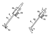
処置用アーム5の先端に取り付けられている処置具4の挿入部4aと観察用アーム7の先端に取り付けられているスコープ6の挿入部6aはそれぞれ、その先端部が図1中に示すa方向及びb方向に湾曲駆動できるようになっている。このような湾曲駆動は、処置具4のサーボモータ収納部4bおよびスコープ6のサーボモータ収納部6b内にそれぞれ設けられたサーボモータ(図示しない)を駆動させて挿入部4a,6a内に挿通配置されたワイヤー(図示しない)を牽引することによって行なわれる。
【0011】
また、処置具4とスコープ6は図1中に示すc方向に回転駆動できるようになっている。このような回転駆動は、フリー関節アームジョイント部4c,6c内に設けられたサーボモータ4d,6dを駆動させて図示しない回転機構を作動させることにより行なわれる。特に、処置具4の先端鉗子部4eにはこの鉗子部4eを開閉させる開閉機構が設けられており、この開閉機構は、サーボモータ収納部4b内に設けられたサーボモータ(図示しない)を駆動させて挿入部4a内に挿通配置されたロッドもしくはワイヤ部材を押し引き操作することにより作動される。
【0012】
ここで、処置具4と処置用アーム5とを組み合わせたものを処置用スレーブマニピュレータと称し、スコープ6と観察用アーム7とを組み合わせたものを観察用スレーブマニピュレータと称することにする。
【0013】
処置用スレーブマニピュレータの入力手段であるマスターアーム8と、観察用スレーブマニピュレータの入力手段であるヘッドマウントディスプレイ9(以下、HMDという。)とが図2に示されている。
【0014】
マスターアーム8は複数のリンク機構で構成されている。リンク機構を構成する各リンクには位置検知用のエンコーダ(図示しない)が設けられている。このエンコーダによって各リンクの動作を検知することで、マスターアーム8の移動量を検知できる。
【0015】
また、操作者がマスターアーム8から手を離した場合にマスターアーム8がその自重によって勝手に動作しないように、マスターアーム8の各アームリンクには電磁クラッチ(図示しない)が取り付けられている。つまり、マスターアーム8は、この電磁クラッチによって、必要以外の時には動かないようにその動作が制限される。また、マスタースレーブモードで実際に処置用スレーブマニピュレータを動かす際、前記電磁クラッチは、フットスイッチ12を踏む動作によって、その作動が制御される。つまり、マスターアーム8の動作のロック及びこのロック状態の解除がフットスイッチ12によって行なえるようになっている。なお、フットスイッチ12は例えば2つのスイッチ12a,12bを有している。
【0016】
ここで、マスタースレーブモードとは、入力手段であるマスターアーム8の動きが処置用スレーブマニピュレータに伝達され得るモード、すなわち、処置用スレーブマニピュレータがマスターアーム8の動きに追従できるモードをいう(後述するHMD9と観察用スレーブマニピュレータとの場合についても同様。)。
【0017】
一方、HMD9は、スコープ6によって観察された映像を表示するディスプレイ(図示しない)を備えている。このディスプレイは、HMD9を術者の頭部に装着した際に術者の目の位置にセットされるように設けられている。また、HMD9は、術者の頭がどのように動いても、スコープ6の先端でとらえられた映像を前記ディスプレイによって常に観察できるような構成になっている。このような構成のHMD9によれば、従来のように処置中に術者が手術室に設置されたTVモニターの方に視線を移すといった煩わしい動作を行なわなくて済むため、操作性が向上する。また、患部から視線を外すことなく常に患部の映像を明確に観察することができるから、安全な手術を行なうことができる。
【0018】
術者の頭部の空間的な移動量は磁気センサー10によって検知される。磁気センサー10は、一様な磁場を発生する磁気センサーソース部10bと、磁気センサーソース部10bからの磁場を検知する磁気センサーセンス部10aとからなる。このうち磁気センサーセンス部10aがHMD9のほぼ中央部に取り付けられている。
【0019】
術者の頭部の動きはこうした磁気センサー10によって検知されるが、その検知方法を簡単に説明すると、HMD9以外の所定の場所にセットされた磁気センサーソース部10bから発生される一様な磁場を磁気センサーセンス部10aで検知し、頭部の動きに伴う磁場の変化分の情報を処理することによって、ソース部10bとセンス部10aとの空間的絶対移動量およびセンス部10aの傾斜であるオイラー角(ロール、ピッチ、ヨー)を求めて、術者の頭部の移動量および傾き量を検知するというものである。
【0020】
次に、処置用スレーブマニピュレータと観察用スレーブマニピュレータの動作を制御する制御装置11について説明する。
図2に示すように、制御装置11は、前記各スレーブマニピュレータを動作させるために必要ないくつかの機能モジュールを具備している。すなわち、図中、11aは、制御装置11の機能モジュールを統括制御する上位CPUであるマイクロコントローラである。11eはマスターアーム8に設けられた前記エンコーダの動作量を保持しておくためのアップダウンカウンタである。当然のことながら、このアップダウンカウンタ11eは、マスターアーム8に取り付けられたエンコーダ分の入力ポートを有している。また、このアップダウンカウンタ11eは、具体的には、マスターアーム8のエンコーダからの相対的移動量に対して初期設定時(制御装置11の電源を立ち上げた時)に予め設定したカウンタ値の増減を行なわすものである。
【0021】
11dは、HMD9に取り付けられた磁気センサーセンス部10aからの情報を検知するための磁気センサーデータインターフェイス回路である。この磁気センサーインターフェイス回路11dには磁気センサー10の絶対位置情報とオイラー角の情報とが磁気センサーセンス部10aから入力される。
【0022】
11fは、キーボード13から入力された情報を受け取るためのキーボードインターフェイス部である。11iは、本実施例におけるマニピュレータシステムの動作情報をフロッピーディスクに記憶するためのフロッピーディスクドライブである。11hはフロッピィディスクドライブ11iをコントロールするためのフロッピィディスクコントローラである。なお、フロッピィディスクに保存される情報としては、観察用・処置用スレーブマニピュレータの教示データや、スケール比、感度等の制御パラメータが挙げられる。ここでは、フロッピィディスクに保存する例を示しているが、当然のことながら、ハードディスク、光磁気ディスクの情報処理装置周辺機器で使用される記憶媒体、あるいは、簡単な素子レベルのEEPROM、バッテリバックアップ付きRAM等を用いても構わない。
【0023】
11gはフットスイッチ12の入力情報を検知するためのフットスイッチインターフェイス部である。11bは、スレーブ側の各構成要素である処置用アーム5、観察用アーム7、処置具4、スコープ6のそれぞれを駆動するためのサーボインターフェイスであり、サーボの高速演算処理を行なうためのディジタルシグナルプロセッサ(以下、DSPという。)を有する。また、11cは、前記DSP11bの処理結果の信号を実際にモータを駆動するために必要なパワーまで増幅するためのサーボドライバである。
【0024】
次に、各機能モジュールのインターフェイスについて説明する。
図2中、制御装置11内に示されている11mはデータバスラインである。このデータバスライン11mは、マイクロコントローラ11aからDSP11bに位置指令を送ったり、スレーブアーム側のサーボ部のエンコーダフィードバック情報を読みとったり、アップダウンカウンタ11e、磁気センサー移動量インターフェイス11d、キーボードインターフェイス部11f、フットスイッチインターフェイス部11g、フロッピーディスクインターフェイス部11hのそれぞれからのデータをマイクロコントローラ11aに取り込んだりするラインである。
【0025】
11jは、DSP11bで得られた制御演算結果をサーボドライバ11cに送るためのアナログ指令ラインである。11kは、サーボドライバ11cからのパワー信号を供給するラインおよびサーボ部フィードバックエンコーダラインである。11uは、フロッピーディスクドライブ11iとフロッピーディスクドライブコントローラ11hとの間でのデータのやりとりを行なうためのデータラインである。11tは、フットスイッチ12とフットスイッチインターフェイス部11gとの間でのデータラインである。11sは、キーボード13とキーボードインターフェイス部11fとの通信を行なうためのデータラインである。
【0026】
なお、前記インターフェイスにおいては、データの受け渡しを行なうデータバスライン11mしか示さなかったが、前記各機能モジュールを選択するためのアドレスバスやコントロールライン等が付加されていることはいうまでもない。また、観察用スレーブマニピュレータと処置用スレーブマニピュレータのサーボ系を駆動するための11jラインおよび11kラインは、アナログ指令ラインのものしか示さなかったが、DSP11bでPID制御則などの制御アルゴリズムを実行するためのエンコーダフィードバック信号ラインも存在する。
【0027】
以上の構成によって、術者の頭の動き(HMD9の動き)に追従(対応)して観察用スレーブマニピュレータが動作されるマスタースレーブ動作が行なわれ、マスターアーム8の操作に追従(対応)して処置用スレーブマニピュレータが動作されるマスタースレーブ動作が行なわれる。
【0028】
すなわち、処置用のマスタースレーブ側では、マスターアーム8に設けられたエンコーダの情報がデータライン11qを介してアップダウンカウンタ11eで読み取られる。このアップダウンカウンタ11eでは、初めにアップダウンカウンタ11eに設定されたデータに対して移動量を増減させるので、絶対的な移動量(マスターアーム8の移動量)が検知できる。このアップダウンカウンタ11e内に保持されているデータはサンプリング毎にマイクロコントローラ11a内にデータバス11mを介して取り込まれる。マイクロコントローラ11a内では、前記移動量に対して処置用スレーブマニピュレータの各軸をどのように動作させるかを決定するための座標変換処理が行なわれる。
【0029】
一方、観察用のマスタースレーブ側でも、HMD9からの情報がデータライン11rを介して磁気センサーデータインターフェイス回路11dに送られ、処置用のマスタースレーブ側とほぼ同様の処理がなされる。
【0030】
さて、このような医療用マニピュレータシステムを腹腔内外科手術に適用した例が図3に示されている。図3は、手術室内における器材のレイアウトを示している。実際には患者の腹腔内を膨らませるための気腹器等の器具が備え付けてあるが、ここでは省略して示している。
【0031】
図示のように、患者2が載置された手術台1のレール3には、手術を行なうために必要な1組の観察用スレーブマニピュレータ27と、2組の処置用スレーブマニピュレータ25a,25bの合計3つのスレーブマニピュレータが設置されている。観察用マニピュレータ27の先端には、先端が電動湾曲する内視鏡6が接続されており、各処置用マニピュレータ25a,25bの先端には、先端が電動で湾曲し且つ開閉動作する処置具4a,4bが接続されている。
【0032】
このような3組のスレーブマニピュレータを制御するために、制御装置11´,11´´が図3に示すように配置されている。すなわち、制御装置11´,11´´は、操作者38によって操作されるマスターマニピュレータ8a,8bおよびHMD9の動作に追従するように、駆動ライン36a,36bを介して各スレームマニピュレータ25a,25b,27の動作を制御している。
【0033】
制御装置11´は、操作者の右手によって操作されるマスターマニピュレータ8aの動きを判断して処置用スレーブマニピュレータ25aを制御するとともに、HMD9によって操作者38の頭の動きを判断して観察用スレーブマニピュレータ27を制御する。また、制御装置11´´は、操作者の左手によって操作されるマスターマニピュレータ8bの動きを判断して処置用スレーブマニピュレータ25bを制御する。
【0034】
すなわち、操作者38の頭にはHMD9が装着されており、このHMD9には磁気センサのセンス部10aが取り付けられている。磁気センサのソース部10bはマスターマニピュレータ8aの所定部位に配置されている。この構成によって、操作者38の頭の動きが検知され、検知された位置情報が信号ライン35を介して制御装置11´に送られる。また、操作者38の右手の動きは、マスターマニピュレータ8aの各関節に設けられたエンコーダ情報としてライン37aを介して制御装置11´に取り込まれる。操作者38の左手の動きは、マスターマニピュレータ8bの各関節に設けられたエンコーダ情報としてライン37bを介して制御装置11´´に取り込まれる。
【0035】
操作者38の足元付近には、2連のフットスイッチ12が配置されている。このフットスイッチ12はライン33を介して制御装置11´に電気的に接続されており、フットスイッチ12の一方のスイッチ12aを踏むことによってマスターマニピュレータ8a,8bの動作が可能となるうような制御が制御装置11´によってなされている。また、フットスイッチ12の他方のスイッチ12bは緊急停止用のスイッチであり、このスイッチ12bを踏むことによって制御装置11´がシステムダウンされ、各スレーブマニピュレータ25a,25b,27の動作が強制的に停止されるようになっている。
【0036】
こうしたスイッチ12a,12bのON/OFF信号は、信号ライン33を介して制御装置11´に送られ、制御装置11´内の処理回路(図示しない)で解析処理される。そして、制御装置11´は、例えば緊急停止状態が生じた時(スイッチ12bが踏まれた時)には、各スレーブマニピュレータ25a,25b,27を同時に停止させるために、信号ライン34を介して制御装置11´をシステムダウンさせる。これによって、制御装置11´によって制御されるスレーブマニピュレータ25a,27の動作は勿論、制御装置11´´によって制御されるスレーブマニピュレータ25bの動作も強制的に停止される。
【0037】
以上説明したように、本実施形態の医療用マニピュレータシステムによれば、観察・処置中にスレーブマニピュレータ25a,25b,27のいずれかが動作不良や暴走を起こした場合に、単なるフットスイッチ12bの踏み操作のみで全てのスレーブマニピュレータ25a,25b,27を確実に停止させることができる。したがって、安全性および操作性が向上する。
【0038】
すなわち、一般に、マニピュレータは、観察・処置中に操作者38の動きに対応して忠実に動作するので、操作者38が意図しない動作を行なった場合に、患者に負担をかけてしまう可能性がある。その場合には、マスタースレーブ動作を行なわせるためのフットスイッチ12aをOFFにすれば良いが、例えば、動作中に各スレーブマニピュレータ25a,25b,27が干渉し合った場合、マスタースレーブモード(フットスイッチ12a)をOFFにしても、マニピュレータのサーボ処理の都合上、指令偏差が残ってしまうため、スレーブマニピュレータ25a,25b,27が動作を行なってしまう可能性がある。しかしながら、こうした場合、本実施形態の医療用マニピュレータシステムでは、フットスイッチ12の緊急スイッチ12bを踏むことによって、全てのスレーブマニピュレータ25a,25b,27の動作を制御している制御装置11´,11´´を強制的にシステムダウンしてしまうため、スレーブマニピュレータ25a,25b,27の干渉による暴走を避けることができるようになる。
【0039】
なお、本実施形態では、緊急停止スイッチがフットスイッチ12の他方のスイッチ12bであったが、操作者が操作するマスターマニピュレータ8a,8bの操作把持部に設けられたハンドスイッチであっても良い。
【0040】
また、各スレーブマニピュレータ25a,25b,27を別個に停止させる複数のフットスイッチを設ければ、全てのスレーブマニピュレータを停止させる必要がなくなり、各スレーブマニピュレータのシステムダウンからの復帰作業に時間をかけなくても済むようになる。この場合、警告ランプ(例えば、緊急停止が生じた時に赤点滅するランプ)を、操作者が見やすい位置、例えば、マニピュレータの近傍や制御装置の近傍等に設置しても良い。また、警告ランプでは大げさであるという場合には、LEDによる表示を行なうようにしても良い。
【0041】
図4は、本発明の第2の実施形態を示すものである。本実施形態の医療用マニピュレータシステムは、第1の実施形態の構成および作用効果に加え、操作者の意図しない動きを制限するもでき、これによって、安全性を向上させることができる。以下、具体的に説明する。
【0042】
図4に示すように、本実施形態の医療用マニピュレータシステムは、第1の実施形態で示した構成(図2および図3参照)に加え、画像処理回路14を備えている。この画像処理回路14は、ペン入力モニター15からの入力情報によって、モニター15の画面上に表示されている範囲内外での処置具4の動作範囲を制限させ、安全性を向上させようとするものである。
【0043】
ペン入力モニター15には、観察用スレーブマニピュレータのスコープ6から信号ライン14aを介して体腔内の画像が写し出される。操作者は、この表示された画像に対し、入力ペン15aでモニター15の画面上をなぞることによって、制限範囲を設定する。ただし、この制限範囲を画像処理回路14に正確に認識させるため、操作者は、制限範囲を示す線(以下、制限線という。)が閉じるようにペン入力する必要がある。
【0044】
このようにして描かれた制限線の情報は、信号ライン15cを介して、画像処理回路14に送信される。画像処理回路14は、この情報に基づいて、制限線によって示された制限範囲がペン入力モニター15のどこの画面の画素に対応しているかを認識するとともに、制限対象となる領域(動作可能領域)がその閉じた制限線の内側の領域か或いは外側の領域かを判断する。これによって、処置用スレーブマニピュレータの先端の動作範囲が制限される。
【0045】
処置具4の先端にはマーキングがついており、画像処理回路14は、これを色抽出することにより、処置具4のマーキング部が画面のどの場所にきているかを認識する。そして、このマーキングの位置が動作可能領域であるか否か(制限線によって囲まれた領域の内側か外側か)を判断し、設定の条件に応じて処置具4を動作・停止させる。それ以外の構成および作用効果は第1の実施形態と同一である。
【0046】
なお、制御装置11のフロッピィディスクFに今回の情報(観察用マニピュレータの位置や動作制限範囲等の情報)を記憶させても良い。これによって、使用毎に設定し直すという煩わしさを解消することができる。また、情報記憶媒体は、フロッピィディスクFである必要はなく、例えばメモリカードや光CD等の媒体であっても良い。
【0047】
以上説明したように、本実施形態の医療用マニピュレータシステムは、処置用スレーブマニピュレータを選択された領域でのみ動作させることによって、操作者の意図しない動作により対象部位以外の生体部位に無理な力をかけてしまうといった事態を回避することができる。したがって、術中の安全性が確保される。
【0048】
図5ないし図9は本発明の第3の実施形態を示すものである。第2の実施形態では、ペン入力によって動作範囲を制限できたが、本実施形態では、画像処理のエッジ検出を用いることによって、対象臓器等の部位での動作限定を行なわすことができる。
【0049】
図5は本実施形態の医療用マニピュレータシステムの構成を示している。図示のように、この医療用マニピュレータシステムには画像処理回路39が設けられており、スコープ6で検出された画像データが画像処理回路39に直接に入力されるようになっている。それ以外の構成は第1の実施形態と同一である。
【0050】
スコープ6で得られた画像データは信号ライン39aを介して画像処理回路39に取り込まれる。取り込まれた画像データは、画像処理の領域分割法(原画像上におけるクラスタリング)によって処理される。この処理は、画像全体を開始点として一定の特徴を持たない領域を細分化していくものであり、最終的に均一な領域になった時点で領域の細分化を停止する。具体的には、4分木(Quad tree)の方法を用い、画像をそれぞれの節点が最大4個の子を持つ木によって表現するものである。なお、これは、画像領域の分割を行なう極めて一般的な方法であるが、その他、原画像上のクラスタリングによるもの、特徴空間におけるクラスタリングによるもの、エッジ検出、さらにはテクスチャ解析によるもの等を用いても構わない。
【0051】
図6に原画像が示されている。この原画像には画像処理回路39によって前述した領域分割が施され、領域分割された画像には各領域に対して番号が付与される。この状態は、信号ライン39bを介して、HMD8の画面に図7のように表示される。
【0052】
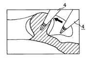
次に、領域のどの部分(臓器や血管等)に対して動作範囲の制限を行なうかを選択決定するために、領域選択が行なわれる。ここでは、図7に示した番号と同じ数値をキーボード入力することによって領域の選択が行なわれる。例えば領域4の選択がなされると、処置具4の先端に配置されたマーキングの位置が図8に示された斜線部領域内(領域4内)に入るように、すなわち、処置具4の先端が図8の矢印の方向に移動するように、処置用スレーブマニピュレータの動作を制御する。なお、この移動は、操作者の操作によるマスタースレーブ動作であっても良いし、制御装置11側のプログラムによる自動的なものであっても良い。
【0053】
以上の作業が終了したら、第2の実施形態と同様に、画像上の処置具4の先端のマーキングの位置と選択された分割領域の範囲位置とを比較することによって、処置用スレーブマニピュレータの動作範囲が限定される。
【0054】
なお、以上は一つの領域部位における動作制限について説明したが、図9に示すように、複数の領域部位を選択し、かつ、斜線領域外でのみ処置用スレーブマニピュレータを動作させるようにすることもできる。
【0055】
以上の一連の動作の一例を以下に示す。
(1)操作者が、キーボード入力により本実施形態で示す動作のコマンドを選択する。その後、画像の領域分割が行なわれ、操作者が装着しているHMDの画面に、分割された画像が表示される。操作者は、その画像を観察し、キーボードの数値キー入力によって、選択したい領域を選択する。
【0056】
(2)次に、操作者が処置用スレーブマニピュレータを動作させ、選択した領域に処置具4の先端のマーキングが入るように処置具4を誘導する。
(3)指定領域に処置具4を挿入した後、マスタースレーブ動作を開始させる。
【0057】
以上説明したように、本実施形態の医療用マニピュレータシステムによれば、任意の臓器を選択し、その臓器の輪郭内外で処置用マニピュレータを動作させることができ、目的とする部位へのアプローチのみを行なうことが可能になる。したがって、意図しない動きを防止することができ、安全性が向上する。
【0058】
図10は本発明の第4の実施形態を示すものである。図10の(a)は、処置用スレーブマニピュレータの先端の処置具4がステープラである場合を示している。この実施例形態のマニピュレータシステムは、画像処理によって胆管の太さを認識し、その胆管にあったステープラ(処置具4)を自動的に選択して処置を行なおうとするものである。
【0059】
本実施形態では、第3の実施形態で示したと同一の画像処理によって形状認識がなされるが、それに加え、胆管Sの太さを抽出することが行なわれる。まず、胆管のどのあたりを切除するかを選択するために、図10の(b)に示すようにHMD9の画面上に表示された円状のポインタPを所望の部位まで誘導する。このポインタPは、例えば制御装置11のキーボードの矢印キーによって、画面の上下左右に移動される。
【0060】
このポインタPが胆管Sの所望の部位を囲むような場所に位置したら、そのポインタPの円の内部にある胆管Sに対してエッジ検出を行なう。そして、このエッジ検出情報から、エッジで囲まれ斜線部分(図10の(d)参照)の矢印で示された方向の距離(胆管Sの太さ)を求める。これは、画面において何画素分であるかを求めることによって実現される。なお、この画素情報では、実際の距離が求められないため、予め決められた尺度と比較する必要がある。そのため、例えば、図10の(b)に示すように、処置具4の鉗子部のグリッパ4aの長さaを画像処理によって抽出し、その時の長さaが何画素分かを求める。この場合、グリッパ4aの長さaは既知であるので、1画素に対してどのくらいの長さであるかを計算することによって現在の胆管Sの太さがおおよそどのくらいかを認識することができる。
【0061】
認識された情報により、ステープラの大きさを選択し、それによって、胆管切除術を行なうことができる(図10の(c)参照)。なお、処置具4のグリッパ4aの長さaを出来るだけ正確に画面の画素に対応させるために、処置具4の長手方向のベクトルを画面に水平になるように配置することが望ましい。
【0062】
以上説明したように、本実施形態の医療用マニピュレータシステムによれば、対象部位の処置に最適な処置具を選択することができるため、例えばステープラを経験的に選択して処置を行なっていた従来よりも操作性の向上を図ることができる。
【0063】
図11および図12は本発明の第5の実施形態を示すものである。本実施形態の医療用マニピュレータシステムは、第2および第3の実施形態のように処置用スレーブマニピュレータの動作範囲を制限することもできるが、それ以外の手段によっても安全性の向上を図ることができる。
【0064】
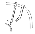
例えば、マスタースレーブモード動作時に、モニタ画面に表示されていない生体内領域に処置用スレーブマニピュレータが位置した場合、操作者は処置具4がどのような状態にあるのかを認識することができない。そこで、本実施形態では、図11に示すように、処置具4の先端に赤外線センサー41を設け、これによって処置具4の位置状態を認識することができる。
【0065】
本実施形態の医療用マニピュレータシステムの構成が図12に示されている。図12に示すように、赤外線センサー41からのデータは、信号ライン51を介して、制御装置11に設けられたセンサー処理回路52に入力されるようになっている。それ以外の構成は第3の実施形態と同一である。
【0066】
赤外線センサー41は、対象部位の発する赤外を検知するためのものであり、処置具4の先端が臓器に近付くと赤外線の量を多く検知することができる。そこで、本実施形態では、赤外線センサー41が所定量の赤外線を検知した場合に、センサー処理回路52がそれを認識し、処置用スレーブマニピュレータの動作が停止されるようになっている。具体的には、例えば、赤外線センサー41からの検知データ値が予め設定された閾値以上であるとセンサー処理回路52で判断された場合には、センサー処理回路52から処置用スレーブマニピュレータを実際に制御しているサーボ処理回路11bに停止命令が送られ、処置用スレーブマニピュレータの動作が停止される。したがって、処置具4の先端が意図しない臓器に接触することを防ぐことができる。
【0067】
なお、本実施形態では、赤外線検知によって臓器に対する処置具4の先端の過度の接近を回避するようにしているが、例えば超音波センサーを用い、超音波の反射波から処置具4の先端の臓器に対する接近度を認識し、処置具4の先端が臓器にある一定距離以上近付きすぎないように制御しても良い。
【0068】
以上説明したように、本実施形態の医療用マニピュレータシステムによれば、操作者が観察できない領域に処置具4が位置した場合でも、処置用スレーブマニピュレータの動作を自動的に停止することができるため、安全性が向上する。
【0069】
ところで、一般に、観察・処置を行なうための器具はその種類が無数にあり、それら全てに対応したマニピュレータをラインアップすることは極めて困難である。そこで、以下、スコープおよび処置具の部分だけを交換することができる医療用マニピュレータシステムについて説明することとする。
【0070】
図13の(a)は、観察・処置用マニピュレータによる内視鏡下外科手術を行なう医療用マニピュレータシステムの構成を示している。図中101は、観察用スコープ102あるいは処置具103を先端に配置可能なロボットアームである。104は患者ベッドで、105は患者である。ロボットアーム101には電動で各関節を駆動させるためのサーボモータが内蔵されており(図示しない)、これらのサーボモータによって、スコープ102および処置具103が所望の位置および方向に動作できるようになっている。また、図中106は、ロボットアーム101とスコープ102あるいは処置具103とを連結させるための機構部であり、ネジ止め式になっている。
【0071】
ところで、ロボットアーム101は、サーボ処理による位置決めを行なっているが、一般にスコープ102の重さと処置具103の重さとはかなり異なっているため、マニピュレータのサーボゲインを最適にするために、ロボットアーム101に取り付ける対象器具によってゲイン調整を行なう必要がある。もし、この調整を行なわないと、マニピュレータの応答性を向上させることができなくなり、強いては操作性が低下してしまう。
【0072】
そこで、本実施形態では、ロボットアーム101のサーボ処理系に自動ゲイン調整手段を設け、常に最適なゲインによるロボットアーム101の駆動を行なわせることができるようにしている。
【0073】
図13の(b)にロボットアーム101の簡単な制御ブロック線図が示されている。図中sはラプラス演算子であり、KP1は比例ゲイン、KI1は積分ゲイン、K2はアンプゲイン、Tは制御対象(ここではモータ)時定数である。
また、θ1は入力位置指令、θ2は位置出力値である。図中点線で囲まれた部分は、第1の実施形態で示したDSPで実現している。そして、このDSPの内部メモリ(図示しない)には、スコープ102を駆動する場合のループゲイン定数(比例ゲイン、積分ゲイン)と処置具103を駆動する場合のループゲイン定数とが予め各々記憶させてあり、動作を行なわせる際に、ループゲイン定数の選択を行なうようになっている。この選択は、制御装置のキーボードからのコマンドによって行われる。
【0074】
ループゲイン定数の選択がされると、DSP側でどのコマンドが設定されたかが認識され、そのコマンドに合うループゲインが選択される。その後、位置決めのためのサーボ処理が行なわれる。また、途中で器具を交換するような事態に対応するために、コマンドの認識は定期的にDSP側で確認される。
【0075】
以上のような制御によれば、簡単な構成で各医療器具に合ったロボットアームのゲイン調整を行なうことができるようになり、常に最適な応答性でロボットアームを駆動させることができ、操作性が向上する。
【0076】
なお、図13の構成では、操作者が自分自身でループゲインの設定を行なわなければならないが、人間による操作では常にヒューマンエラーによる設定ミスが予測されるため、制御装置自身が負荷の推定を行ない、制御装置自身でループゲインを設定する制御構成について以下説明することとする。
【0077】
図14の(a)にそのブロック線図を示す。図中K2はアンプゲイン、Jはモータのイナーシャ、K1はモータトルク定数である。図中点線で囲まれた111はモータ部を示している。110はDSPである。ただし、アンプは、指令通りの電流をモータに流せるようになっている。具体的には、電流フィードバックが設けられる。図中、θ1が入力指令であり、θ2が出力値である。図に示すように、θ2はライン112を介してDSP110側にフィードバックされている。
【0078】
図14(b)は、図14(a)の系のモータ電流指令(i)と位置出力との間に、図中点線の部分のブロック線図を追加してものである。また、図中dは、モータ軸にかかる外乱を表わしている。
【0079】
この構成において、ライン115から出力される外乱トルクdは、
(J/J)(K1+d)−K1 …………(1)
という演算から求められる。ここで、モータ軸換算負荷がJからJ1に変化したとすると、
(J/J1)(K1+d)−K1 …………(2)
から求められる外乱トルクdがライン115から出力される。
【0080】
実際には、ブロック線図の点線内は、DSP等による高速サンプリングを行なっているため、外乱トルクdが急激に変化しない(ライン115の出力が変わらない)。したがって、モータ軸換算イナーシャは上式(1)および(2)より、
J=J1
となる。
【0081】
これによって、負荷がどの程度変わったかが認識されるため、例えば、DSPのメモリに各取り付け器具の換算イナーシャJを記憶しておき比較することによって、自動的に取り付け器具の推定が可能になる。これによって、DSP側で自動的に負荷にあったゲイン調整が可能となる。
【0082】
以上説明した制御によれば、ヒューマンエラーを自動的になくすことが可能であるため、誤操作による操作性低下を防ぐことができる。
なお、以上説明してきた態様により、以下の項で示す各種の構成が得られる。また、以下の項で示す各種の構成は、任意に組み合わせても良い。
【0083】
1.生体内組織部位の観察と処置の少なくとも一方を行なう器具を保持する複数の多関節手術用マニピュレータと、
前記多関節手術用マニピュレータを操作するための操作手段と、
前記操作手段からの操作情報に基づいて前記多関節手術用マニピュレータの動作を制御する制御手段と、
操作者の操作可能な部位に設けられ、前記多関節手術用マニピュレータの少なくとも1つの動作を強制的に停止させる強制停止手段と、
とを具備することを特徴とする医療用マニピュレータシステム。
【0084】
2.前記強制停止手段は、全てのマニピュレータの動作を停止させることを特徴とする第1項に記載の医療用マニピュレータシステム。
3.前記強制停止手段は、所望のマニピュレータの動作を選択的に停止させることを特徴とする第1項に記載の医療用マニピュレータシステム。
【0085】
4.前記強制停止手段が個々のマニピュレータの近傍に設けられていることを特徴とする第3項に記載の医療用マニピュレータシステム。
5.前記強制停止手段が個々のマニピュレータを制御する制御装置の近傍に設けられていることを特徴とする第3項に記載の医療用マニピュレータシステム。
【0086】
6.前記強制停止手段がハンドスイッチであることを特徴とする第2項ないし第5項のいずれか1項に記載の医療用マニピュレータシステム。
7.前記強制停止手段がフットスイッチであることを特徴とする第2項ないし第5項のいずれか1項に記載の医療用マニピュレータシステム。
【0087】
8.マニピュレータが停止した時に点滅する警告手段を個々のマニピュレータの近傍に設けたことを特徴とする第1項に記載の医療用マニピュレータシステム。
【0088】
9.前記警告手段が色付きランプであることを特徴とする第8項に記載の医療用マニピュレータシステム。
10.前記警告手段がLEDであることを特徴とする第8項に記載の医療用マニピュレータシステム。
【0089】
11.生体内組織部位の観察を行なう観察器具を保持する観察用多関節マニピュレータと、
生体内組織部位の処置を行なう処置器具を保持する少なくとも1つの処置用多関節マニピュレータと、
前記多関節マニピュレータの両者を操作するための操作手段と、
前記操作手段からの操作情報に基づいて前記多関節マニピュレータの動作を制御する制御手段と、
前記観察器具からの情報を画像情報として出力する表示手段と、
前記表示手段に表示された画像の任意の範囲を選択するための画像選択手段とを具備し、
前記多関節マニピュレータに保持された少なくとも観察または処置を行うための器具の先端近傍部が前記画像選択手段によって選択された範囲内にある時にのみマニピュレータの動作を可能とする動作判断手段が設けられていることを特徴とする医療用マニピュレータシステム。
【0090】
12.前記画像選択手段は、前記表示手段によって表示された観察画像上にペン入力によって選択することを特徴とする第11項に記載の医療用マニピュレータシステム。
【0091】
13.前記動作判断手段は、画像処理による色抽出によるものであることを特徴とする第11項に記載の医療用マニピュレータシステム。
14.生体内組織部位の観察器具を保持する多関節手術用マニピュレータと、この多関節手術用マニピュレータを操作するための操作手段と、この操作手段からの操作情報に基づいて前記多関節手術用マニピュレータの動作を制御する制御手段と、前記観察器具からの情報を画像情報として出力する表示手段と、表示手段に表示された画像の任意の範囲を選択するための画像選択手段とを有する医療用マニピュレータシステムにおいて、前記画像選択手段が画像処理の領域選択によるものであることを特徴とする医療用マニピュレータシステム。
【0092】
15.前記領域選択手段が原画像上におけるクラスタリングを用いることを特徴とする第14項に記載の医療用マニピュレータシステム。
16.前記領域選択手段が特徴空間におけるクラスタリングを用いることを特徴とする第14項に記載の医療用マニピュレータシステム。
【0093】
17.前記領域選択手段が原画像中のエッジを用いることを特徴とする第14項に記載の医療用マニピュレータシステム。
18.前記領域選択手段がテクスチャ解析を用いることを特徴とする第14項に記載の医療用マニピュレータシステム。
【0094】
19.生体内組織部位の観察と処置の少なくとも一方の器具を保持する多関節手術用マニピュレータと、この多関節手術用マニピュレータを操作するための操作手段と、この操作手段からの操作情報に基づいて前記多関節手術用マニピュレータの動作を制御する制御手段とを有する医療用マニピュレータシステムにおいて、前記処置器具先端近傍が臓器付近に近付いた時にマニピュレータの動作を停止させるための動作制御判断手段を設けたことを特徴とする医療用マニピュレータシステム。
【0095】
20.前記動作制御判断手段は、処置器具に取り付けられたセンサーと、センサから出力された情報が一定値を超えたら動作停止させるための処理回路とからなることを特徴とする第19項に記載の医療用マニピュレータシステム。
【0096】
21.前記センサが圧電素子センサであることを特徴とする第20項に記載の医療用マニピュレータシステム。
22.前記センサが赤外線検知センサであることを特徴とする第20項に記載の医療用マニピュレータシステム。
【0097】
23.生体内組織部位の観察と処置の少なくとも一方の器具を保持する多関節手術用マニピュレータと、この多関節手術用マニピュレータを操作するための操作手段と、この操作手段からの操作情報に基づいて前記多関節手術用マニピュレータの動作を制御する位置決めサーボ制御手段とを有する医療用マニピュレータシステムにおいて、前記器具に応じて前記マニピュレータのサーボゲインの値に切換え可能なサーボゲイン切換え手段を有する。
【0098】
24.生体内組織部位の観察と処置の少なくとも一方の器具を保持する多関節手術用マニピュレータと、この多関節手術用マニピュレータを操作するための操作手段と、この操作手段からの操作情報に基づいて前記多関節手術用マニピュレータの動作を制御する位置決めサーボ制御手段と、前記器具に応じて前記マニピュレータのサーボゲインの値に切換え可能なサーボゲイン切換え手段とを有する医療用マニピュレータシステムにおいて、
前記マニピュレータのサーボゲイン切換え手段は、予め設定された観察器具のサーボゲインと処置器具のサーボゲインとを切り換える切り換え手段であることを特徴とする医療用マニピュレータシステム。
【0099】
25.前記切り換え手段は、自動的に切り換わるように自動識別手段を有していることを特徴とする第23項に記載の医療用マニピュレータシステム。
26.前記自動識別手段が負荷の慣性を識別することによる識別装置であることを特徴とする第23項に記載の医療用マニピュレータシステム。
【0100】
【発明の効果】
以上説明したように、本発明の医療用マニピュレータシステムによれば、
複数の医療用マニピュレータを使用した手術においてマニピュレータに何等かの動作不良が生じた場合でも、それに対して速やかに対処できる。したがって、安全性および操作性に優れ、手術時間を短縮でき、患者に対する侵襲を低くすることができる。
【図面の簡単な説明】
【図1】本発明の第1の実施形態に係る医療用マニピュレータシステムを構成するマニピュレータの処置具およびスコープの作動機構を概略的に示す構成図である。
【図2】本発明の第1の実施形態に係る医療用マニピュレータシステムの構成図である。
【図3】本発明の第1の実施形態に係る医療用マニピュレータシステムの具体例を示す構成図である。
【図4】本発明の第2の実施形態に係る医療用マニピュレータシステムの構成図である。
【図5】本発明の第3の実施形態に係る医療用マニピュレータシステムの構成図である。
【図6】スコープによって得られた原画像である。
【図7】領域分割された図6の原画像の各領域に対して番号が付与された表示例を示す図である。
【図8】処置具の先端に配置されたマーキングの位置が原画像の一定の領域内に入る様子を示す図である
【図9】複数の制限領域が指定された画像表示例を示す図である。
【図10】本発明の第4の実施形態を示し、胆管の太さを抽出して切除する一連の過程を示す図である。
【図11】本発明の第5の実施形態に係わり、赤外線センサを用いた動作制限の態様を示す図である。
【図12】本発明の第5の実施形態に係る医療用マニピュレータシステムの構成図である。
【図13】(a)はスコープおよび処置具の部分だけを交換することができる医療用マニピュレータシステムの一例を示す図、(b)は(a)のシステムの制御ブロック線図である。
【図14】制御装置自身でループゲインを設定するようにしたシステムのブロック線図である。
【符号の説明】
4…処置具、5…処置用アーム(多関節手術用マニピュレータ)、6…スコープ、7…観察用アーム(多関節手術用マニピュレータ)、8…マスターアーム(操作手段)、9…HMD(操作手段)、12b…フットスイッチ。[0001]
[Industrial technical field]
The present invention relates to a medical manipulator system in which a manipulator inserted into, for example, a body cavity of a living body is remotely operated by an operating means to perform a diagnosis or treatment operation.
[0002]
[Prior art]
In recent years, research on medical treatment using robots has been conducted in order to save labor in medical facilities. In particular, in the surgical field, a surgical robot system has been proposed in which a hip replacement of a patient is precisely treated by a multi-degree-of-freedom manipulator (Japanese Patent Laid-Open No. Hei 4-231034). In addition, a robot system that performs an operation endoscopically in order to accurately obtain position information in a patient's body cavity has also been proposed. (Japanese Patent Application No. 5-90989).
[0003]
In recent years, an insertion hole is formed in a body wall such as an abdominal cavity, and an endoscope or a treatment tool is percutaneously inserted into the body cavity through the insertion hole, thereby performing various treatments in the body cavity. Surgery is actively performed. Such a technique is widely performed as a minimally invasive technique that does not require a large incision, such as a cholecystectomy operation or an operation that removes and removes a part of the lung. And in order to improve the operativity in such an operation method, the medical manipulator by a master slave system is devised. For example, in the master-slave manipulator disclosed in Japanese Patent Application No. 5-354039, the operation means is portable, thereby increasing the degree of freedom of operation by the operator.
[0004]
[Problems to be solved by the invention]
By the way, a plurality of medical manipulators are used in complicated and diverse operations.
However, in surgery using a plurality of medical manipulators, for example, if some manipulators perform unintended operations, take some measures to prevent the manipulators from running away and applying excessive force to the operator or patient. It is necessary to take. For example, the operator must determine which manipulator control device should be brought down. Making such a determination during the operation is very complicated. Further, in an operation that progresses momentarily, it is necessary to promptly deal with the surgeon.
[0005]
The present invention has been made paying attention to the above circumstances, and the purpose of the present invention is to promptly cope with any malfunction in the manipulator during surgery using a plurality of medical manipulators. An object of the present invention is to provide a medical manipulator system that is excellent in safety and operability.
[0006]
[Means for Solving the Problems]
In order to solve the above-described problems, a medical manipulator system according to the present invention includes a first multi-joint surgical manipulator that holds an instrument that performs at least one of observation and treatment of an in vivo tissue site, and an in vivo tissue site. A second multi-joint surgical manipulator for holding an instrument for performing at least one of observation and treatment; first operating means for operating the first multi-joint surgical manipulator; and the second multi-joint Second operating means for operating the surgical manipulator, first control means for controlling the operation of the first articulated surgical manipulator based on operation information from the first operating means, A second control means for controlling the operation of the second articulated surgical manipulator based on operation information from the second control means, and a part operable by the operator; Arranged in combination with means for generating an input enabling operation by the first and second operating means, A forced stop input means for generating a signal for stopping the articulated manipulator and outputting the signal to the first control means, wherein the first control means outputs the forced stop input means. A signal for forcibly stopping the operation of the first multi-joint surgical manipulator based on the signal and forcing the second control means to stop the operation of the second multi-joint surgical manipulator Is transmitted.
The medical manipulator system according to the present invention includes a first multi-joint surgical manipulator that holds an instrument that performs at least one of observation and treatment of a living tissue site, and at least observation and treatment of a living tissue site. A second multi-joint surgical manipulator holding an instrument for performing one; a first operating means for operating the first multi-joint surgical manipulator; and operating the second multi-joint surgical manipulator A second control means for controlling the operation of the first multi-joint surgical manipulator based on operation information from the first control means, and a second control means Second control means for controlling the operation of the second multi-joint surgical manipulator based on the operation information, and provided in a part operable by the operator, Arranged in combination with means for generating an input enabling operation by the first and second operating means, A forced stop input means for generating a signal for stopping the articulated manipulator and outputting the signal to the first control means, wherein the first control means outputs the forced stop input means. Based on the signal, the operation of the first articulated surgical manipulator is forcibly stopped, or the operation of the second articulated surgical manipulator is forcibly stopped by the second control means. A signal is transmitted.
The medical manipulator system according to the present invention includes a first multi-joint surgical manipulator that holds an instrument that performs at least one of observation and treatment of a living tissue site, and at least observation and treatment of a living tissue site. A second multi-joint surgical manipulator holding an instrument for performing one; a first operating means for operating the first multi-joint surgical manipulator; and operating the second multi-joint surgical manipulator A second control means for controlling the operation of the first multi-joint surgical manipulator based on operation information from the first control means, and a second control means Second control means for controlling the operation of the second multi-joint surgical manipulator based on the operation information, and provided in a part operable by the operator, Arranged in combination with means for generating an input enabling operation by the first and second operating means, A forced stop input means for generating a signal for stopping the articulated manipulator and outputting the signal to the first control means, wherein the first control means outputs the forced stop input means. Based on the signal, the operation of the first articulated surgical manipulator is forcibly stopped, or the operation of the second articulated surgical manipulator is forcibly stopped by the second control means. It is characterized by performing at least one of sending a signal.
Further, the medical manipulator system of the present invention operates a plurality of articulated surgical manipulators that operate a plurality of articulated surgical manipulators that hold an instrument that performs at least one of observation and treatment of a tissue part in a living body, thereby operating the articulated surgical manipulator. Operating means for performing, operable input means for enabling operation of the operating means, Arranged in combination with the operable input means, Forced stop input means for performing an input for forcibly stopping the operation of the articulated surgical manipulator, and when the operable input is made by the operable input means, the articulated joint according to the operation of the operating means Control means for forcibly stopping the operations of the plurality of articulated surgical manipulators when a surgical manipulator is operated and a stop input is made by the forced stop input means.
[0007]
DETAILED DESCRIPTION OF THE INVENTION
Hereinafter, embodiments of the present invention will be described with reference to the drawings. 1 to 3 show a first embodiment of the present invention.
FIG. 2 shows an example of the medical manipulator system of this embodiment. In FIG. 2, 1 is an operating table for observing and treating a patient, and 2 is a patient.
[0008]
The connection between the
[0009]
The
[0010]
The insertion portion 4a of the treatment instrument 4 attached to the distal end of the
[0011]
Further, the treatment instrument 4 and the scope 6 can be driven to rotate in the direction c shown in FIG. Such rotation driving is performed by driving
[0012]
Here, a combination of the treatment instrument 4 and the
[0013]
FIG. 2 shows a master arm 8 which is an input means of the treatment slave manipulator and a head mounted display 9 (hereinafter referred to as HMD) which is an input means of the observation slave manipulator.
[0014]
The master arm 8 is composed of a plurality of link mechanisms. Each link constituting the link mechanism is provided with an encoder (not shown) for position detection. By detecting the operation of each link by this encoder, the amount of movement of the master arm 8 can be detected.
[0015]
In addition, an electromagnetic clutch (not shown) is attached to each arm link of the master arm 8 so that the master arm 8 does not operate freely due to its own weight when the operator releases his hand from the master arm 8. That is, the operation of the master arm 8 is restricted by this electromagnetic clutch so that it does not move when it is not necessary. Further, when the treatment slave manipulator is actually moved in the master-slave mode, the operation of the electromagnetic clutch is controlled by the operation of stepping on the
[0016]
Here, the master-slave mode refers to a mode in which the movement of the master arm 8 as an input means can be transmitted to the treatment slave manipulator, that is, a mode in which the treatment slave manipulator can follow the movement of the master arm 8 (described later). The same applies to the case of the
[0017]
On the other hand, the
[0018]
The amount of spatial movement of the operator's head is detected by the
[0019]
The movement of the surgeon's head is detected by such a
[0020]
Next, the control device 11 that controls the operations of the treatment slave manipulator and the observation slave manipulator will be described.
As shown in FIG. 2, the control device 11 includes several functional modules necessary for operating the slave manipulators. That is, in the figure, 11a is a microcontroller that is a host CPU that performs overall control of the functional modules of the control device 11. Reference numeral 11e denotes an up / down counter for holding the operation amount of the encoder provided in the master arm 8. As a matter of course, the up / down counter 11e has an input port for an encoder attached to the master arm 8. In addition, the up / down counter 11e has a counter value set in advance at the time of initial setting (when the control device 11 is turned on) with respect to the relative movement amount of the master arm 8 from the encoder. Increase or decrease.
[0021]
Reference numeral 11d denotes a magnetic sensor data interface circuit for detecting information from the magnetic sensor sense unit 10a attached to the
[0022]
Reference numeral 11 f denotes a keyboard interface unit for receiving information input from the
[0023]
11 g is a foot switch interface unit for detecting input information of the
[0024]
Next, the interface of each functional module will be described.
In FIG. 2, 11m shown in the control device 11 is a data bus line. The data bus line 11m sends a position command from the microcontroller 11a to the DSP 11b, reads the encoder feedback information of the slave arm servo section, the up / down counter 11e, the magnetic sensor movement amount interface 11d, the keyboard interface section 11f, This is a line for fetching data from the foot switch interface unit 11g and the floppy disk interface unit 11h into the microcontroller 11a.
[0025]
11j is an analog command line for sending the control calculation result obtained by the DSP 11b to the servo driver 11c. 11k is a line for supplying a power signal from the servo driver 11c and a servo unit feedback encoder line. Reference numeral 11u denotes a data line for exchanging data between the floppy disk drive 11i and the floppy disk drive controller 11h. 11t is a data line between the
[0026]
In the interface, only the data bus line 11m for exchanging data is shown, but it goes without saying that an address bus and a control line for selecting each functional module are added. Further, the 11j line and 11k line for driving the servo system of the observation slave manipulator and the treatment slave manipulator only show analog command lines, but the DSP 11b executes a control algorithm such as a PID control rule. There are also encoder feedback signal lines.
[0027]
With the above configuration, a master slave operation is performed in which the observation slave manipulator is operated following (corresponding to) the movement of the operator's head (the movement of the HMD 9), and following (corresponding) the operation of the master arm 8. A master-slave operation is performed in which the treatment slave manipulator is operated.
[0028]
That is, on the master slave side for treatment, information of the encoder provided in the master arm 8 is read by the up / down counter 11e via the data line 11q. In the up / down counter 11e, the movement amount is increased or decreased with respect to the data initially set in the up / down counter 11e, so that the absolute movement amount (movement amount of the master arm 8) can be detected. The data held in the up / down counter 11e is taken into the microcontroller 11a via the data bus 11m every sampling. In the microcontroller 11a, a coordinate conversion process is performed to determine how to operate each axis of the treatment slave manipulator with respect to the movement amount.
[0029]
On the other hand, on the observation master / slave side, information from the
[0030]
An example in which such a medical manipulator system is applied to intraperitoneal surgery is shown in FIG. FIG. 3 shows the layout of the equipment in the operating room. Actually, an instrument such as an abdominal cavity for inflating the abdominal cavity of the patient is provided, but is omitted here.
[0031]
As shown in the figure, the
[0032]
In order to control such three sets of slave manipulators, control devices 11 'and 11''are arranged as shown in FIG. That is, the control devices 11 ′ and 11 ″ are configured to follow the operations of the
[0033]
The control device 11 'determines the movement of the master manipulator 8a operated by the operator's right hand to control the treatment slave manipulator 25a, and also determines the movement of the head of the
[0034]
In other words, the
[0035]
Two foot switches 12 are arranged near the foot of the
[0036]
Such ON / OFF signals of the
[0037]
As described above, according to the medical manipulator system of the present embodiment, when any of the
[0038]
That is, in general, since the manipulator operates faithfully in response to the movement of the
[0039]
In the present embodiment, the emergency stop switch is the
[0040]
In addition, if a plurality of foot switches for individually stopping the
[0041]
FIG. 4 shows a second embodiment of the present invention. The medical manipulator system of the present embodiment can limit unintended movement of the operator in addition to the configuration and operational effects of the first embodiment, thereby improving safety. This will be specifically described below.
[0042]
As shown in FIG. 4, the medical manipulator system of this embodiment includes an
[0043]
On the pen input monitor 15, an image in the body cavity is projected from the scope 6 of the observation slave manipulator through the signal line 14a. The operator sets a limit range for the displayed image by tracing the screen of the
[0044]
Information on the restriction line drawn in this way is transmitted to the
[0045]
The distal end of the treatment instrument 4 is marked, and the
[0046]
The current information (information such as the position of the manipulator for observation and the operation restriction range) may be stored in the floppy disk F of the control device 11. Thereby, the troublesomeness of resetting every use can be eliminated. The information storage medium does not have to be the floppy disk F, and may be a medium such as a memory card or an optical CD.
[0047]
As described above, the medical manipulator system according to the present embodiment operates the slave slave manipulator for treatment only in a selected region, thereby applying an unreasonable force to a living body part other than the target part due to an operation not intended by the operator. It is possible to avoid such a situation. Therefore, intraoperative safety is ensured.
[0048]
5 to 9 show a third embodiment of the present invention. In the second embodiment, the operation range can be limited by pen input. However, in this embodiment, it is possible to limit the operation in a region such as a target organ by using edge detection of image processing.
[0049]
FIG. 5 shows the configuration of the medical manipulator system of this embodiment. As shown in the figure, this medical manipulator system is provided with an
[0050]
Image data obtained by the scope 6 is taken into the
[0051]
The original image is shown in FIG. The original image is subjected to the above-described region division by the
[0052]
Next, region selection is performed in order to select and determine which part (organ, blood vessel, etc.) of the region the operation range is limited. Here, the area is selected by inputting the same numerical value as the number shown in FIG. For example, when the region 4 is selected, the position of the marking arranged at the distal end of the treatment instrument 4 is within the shaded area (in the region 4) shown in FIG. Controls the operation of the treatment slave manipulator so as to move in the direction of the arrow in FIG. This movement may be a master-slave operation by an operator's operation, or may be automatic by a program on the control device 11 side.
[0053]
When the above operation is completed, as in the second embodiment, the operation of the treatment slave manipulator is performed by comparing the marking position of the tip of the treatment instrument 4 on the image with the range position of the selected divided region. The range is limited.
[0054]
In the above, the operation restriction in one region part has been described. However, as shown in FIG. 9, it is also possible to select a plurality of region parts and operate the treatment slave manipulator only outside the shaded area. it can.
[0055]
An example of the above series of operations is shown below.
(1) An operator selects an operation command shown in this embodiment by keyboard input. Thereafter, the image is divided into regions, and the divided images are displayed on the screen of the HMD worn by the operator. The operator observes the image and selects an area to be selected by numerical key input on the keyboard.
[0056]
(2) Next, the operator operates the treatment slave manipulator to guide the treatment tool 4 so that the marking at the tip of the treatment tool 4 enters the selected region.
(3) After the treatment instrument 4 is inserted into the designated area, the master-slave operation is started.
[0057]
As described above, according to the medical manipulator system of the present embodiment, an arbitrary organ can be selected and the treatment manipulator can be operated within and outside the contour of the organ, and only an approach to a target site can be performed. It becomes possible to do. Therefore, unintended movement can be prevented and safety is improved.
[0058]
FIG. 10 shows a fourth embodiment of the present invention. FIG. 10A shows a case where the treatment tool 4 at the tip of the treatment slave manipulator is a stapler. The manipulator system according to this embodiment recognizes the thickness of a bile duct by image processing, and automatically selects a stapler (treatment instrument 4) suitable for the bile duct to perform a treatment.
[0059]
In this embodiment, shape recognition is performed by the same image processing as shown in the third embodiment, but in addition, the thickness of the bile duct S is extracted. First, in order to select which part of the bile duct is to be excised, a circular pointer P displayed on the screen of the
[0060]
When the pointer P is positioned so as to surround a desired part of the bile duct S, edge detection is performed on the bile duct S inside the circle of the pointer P. Then, from this edge detection information, the distance (thickness of the bile duct S) in the direction indicated by the arrow in the hatched portion (see FIG. 10D) surrounded by the edge is obtained. This is realized by determining how many pixels are on the screen. In this pixel information, since the actual distance cannot be obtained, it is necessary to compare it with a predetermined scale. Therefore, for example, as shown in FIG. 10 (b), the length a of the gripper 4a of the forceps portion of the treatment instrument 4 is extracted by image processing, and how many pixels the length a at that time is obtained. In this case, since the length a of the gripper 4a is known, it is possible to recognize the approximate thickness of the current bile duct S by calculating the length of one pixel.
[0061]
Based on the recognized information, the size of the stapler can be selected, thereby performing a bile duct resection (see FIG. 10C). In order to make the length a of the gripper 4a of the treatment instrument 4 correspond to the pixels of the screen as accurately as possible, it is desirable to arrange the vectors in the longitudinal direction of the treatment instrument 4 so as to be horizontal to the screen.
[0062]
As described above, according to the medical manipulator system of the present embodiment, since it is possible to select a treatment instrument that is optimal for the treatment of the target site, for example, the conventional treatment has been performed by selecting a stapler empirically. Therefore, the operability can be improved.
[0063]
11 and 12 show a fifth embodiment of the present invention. The medical manipulator system of the present embodiment can limit the operation range of the treatment slave manipulator as in the second and third embodiments, but the safety can be improved by other means. it can.
[0064]
For example, when the treatment slave manipulator is positioned in an in-vivo region that is not displayed on the monitor screen during the master-slave mode operation, the operator cannot recognize what state the treatment instrument 4 is in. Therefore, in the present embodiment, as shown in FIG. 11, an
[0065]
The configuration of the medical manipulator system of this embodiment is shown in FIG. As shown in FIG. 12, data from the
[0066]
The
[0067]
In the present embodiment, excessive detection of the distal end of the treatment instrument 4 with respect to the organ is avoided by infrared detection. However, for example, an ultrasonic sensor is used to detect the organ at the distal end of the treatment instrument 4 from the reflected wave of the ultrasonic wave. The degree of approach may be recognized, and control may be performed so that the distal end of the treatment instrument 4 does not approach the organ more than a certain distance.
[0068]
As described above, according to the medical manipulator system of the present embodiment, the operation of the treatment slave manipulator can be automatically stopped even when the treatment tool 4 is located in an area where the operator cannot observe. , Improve safety.
[0069]
By the way, in general, there are innumerable types of instruments for observation and treatment, and it is extremely difficult to line up manipulators corresponding to all of them. Therefore, hereinafter, a medical manipulator system capable of exchanging only the scope and the treatment instrument will be described.
[0070]
FIG. 13A shows the configuration of a medical manipulator system that performs endoscopic surgery using an observation / treatment manipulator. In the figure,
[0071]
By the way, the
[0072]
Therefore, in the present embodiment, an automatic gain adjusting means is provided in the servo processing system of the
[0073]
FIG. 13B shows a simple control block diagram of the
Θ1 is an input position command, and θ2 is a position output value. A portion surrounded by a dotted line in the figure is realized by the DSP shown in the first embodiment. In the DSP internal memory (not shown), a loop gain constant (proportional gain, integral gain) for driving the
[0074]
When the loop gain constant is selected, it is recognized which command is set on the DSP side, and a loop gain suitable for the command is selected. Thereafter, servo processing for positioning is performed. In addition, in order to cope with a situation in which the instrument is changed on the way, the recognition of the command is periodically confirmed on the DSP side.
[0075]
According to the control as described above, the gain adjustment of the robot arm suitable for each medical instrument can be performed with a simple configuration, and the robot arm can always be driven with the optimum responsiveness. Will improve.
[0076]
In the configuration shown in FIG. 13, the operator must set the loop gain by himself. However, since a setting error due to a human error is always predicted in a human operation, the control device itself estimates the load. The control configuration in which the control device itself sets the loop gain will be described below.
[0077]
FIG. 14A shows a block diagram thereof. In the figure, K2 is an amplifier gain, J is a motor inertia, and K1 is a motor torque constant. In the figure, 111 surrounded by a dotted line indicates a motor unit. 110 is a DSP. However, the amplifier can pass a current as commanded to the motor. Specifically, current feedback is provided. In the figure, θ1 is an input command, and θ2 is an output value. As shown in the figure, θ2 is fed back to the
[0078]
FIG. 14B is a diagram in which a block diagram of a dotted line portion is added between the motor current command (i) and the position output in the system of FIG. Further, d in the figure represents a disturbance applied to the motor shaft.
[0079]
In this configuration, the disturbance torque d output from the
(J / J) (K1 + d) −K1 (1)
It is calculated from the operation. Here, if the motor shaft conversion load changes from J to J1,
(J / J1) (K1 + d) −K1 (2)
The disturbance torque d obtained from the above is output from the
[0080]
Actually, the disturbance torque d does not change abruptly (the output of the
J = J1
It becomes.
[0081]
As a result, it is recognized how much the load has changed. For example, by storing and comparing the converted inertia J of each attachment device in the memory of the DSP, the attachment device can be automatically estimated. As a result, gain adjustment suitable for the load can be automatically performed on the DSP side.
[0082]
According to the control described above, since it is possible to automatically eliminate human errors, it is possible to prevent operability deterioration due to erroneous operations.
In addition, according to the aspect demonstrated above, the various structure shown by the following items is obtained. The various configurations shown in the following sections may be arbitrarily combined.
[0083]
1. A plurality of multi-joint surgical manipulators holding an instrument for performing at least one of observation and treatment of a tissue site in a living body;
Operating means for operating the articulated manipulator;
Control means for controlling the operation of the articulated manipulator based on operation information from the operation means;
A forced stop means provided at a site operable by an operator and forcibly stopping at least one operation of the articulated manipulator;
A medical manipulator system comprising:
[0084]
2. The medical manipulator system according to
3. The medical manipulator system according to
[0085]
4). 4. The medical manipulator system according to
5. 4. The medical manipulator system according to
[0086]
6). The medical manipulator system according to any one of
7. The medical manipulator system according to any one of
[0087]
8). 2. The medical manipulator system according to
[0088]
9. 9. The medical manipulator system according to claim 8, wherein the warning means is a colored lamp.
10. The medical manipulator system according to claim 8, wherein the warning means is an LED.
[0089]
11. A multi-joint manipulator for observation holding an observation instrument for observing a tissue part in a living body;
At least one treatment articulated manipulator holding a treatment instrument for treating a tissue site in vivo;
Operating means for operating both of the articulated manipulators;
Control means for controlling the operation of the articulated manipulator based on operation information from the operation means;
Display means for outputting information from the observation instrument as image information;
Image selection means for selecting an arbitrary range of the image displayed on the display means,
Operation determining means is provided that enables operation of the manipulator only when the vicinity of the distal end of the instrument for performing at least observation or treatment held by the articulated manipulator is within the range selected by the image selection means. A medical manipulator system characterized by comprising:
[0090]
12 The medical manipulator system according to claim 11, wherein the image selection means selects the observation image displayed by the display means by pen input.
[0091]
13. 12. The medical manipulator system according to item 11, wherein the operation determining means is based on color extraction by image processing.
14 A multi-joint surgical manipulator that holds an observation instrument for a tissue part in a living body, an operation means for operating the multi-joint surgical manipulator, and an operation of the multi-joint surgical manipulator based on operation information from the operation means A medical manipulator system comprising: control means for controlling the display; display means for outputting information from the observation instrument as image information; and image selection means for selecting an arbitrary range of the image displayed on the display means. The medical manipulator system is characterized in that the image selection means is based on image processing area selection.
[0092]
15. 15. The medical manipulator system according to
16. 15. The medical manipulator system according to
[0093]
17. 15. The medical manipulator system according to
18. 15. The medical manipulator system according to
[0094]
19. A multi-joint surgical manipulator that holds at least one instrument for observing and treating in-vivo tissue sites, an operating means for operating the multi-jointed surgical manipulator, and the multi-joint surgical manipulator based on operation information from the operating means. A medical manipulator system having a control means for controlling the operation of a manipulator for joint surgery, comprising an operation control determining means for stopping the operation of the manipulator when the vicinity of the distal end of the treatment instrument approaches the vicinity of an organ. Medical manipulator system.
[0095]
20.
[0096]
21. 21. The medical manipulator system according to
22. 21. The medical manipulator system according to
[0097]
23. A multi-joint surgical manipulator that holds at least one instrument for observing and treating in-vivo tissue sites, an operating means for operating the multi-jointed surgical manipulator, and the multi-joint surgical manipulator based on operation information from the operating means. A medical manipulator system having a positioning servo control means for controlling the operation of the manipulator for joint surgery has a servo gain switching means capable of switching to a servo gain value of the manipulator according to the instrument.
[0098]
24. A multi-joint surgical manipulator that holds at least one instrument for observing and treating in-vivo tissue sites, an operating means for operating the multi-jointed surgical manipulator, and the multi-joint surgical manipulator based on operation information from the operating means. In a medical manipulator system having positioning servo control means for controlling the operation of a manipulator for joint surgery, and servo gain switching means that can be switched to a servo gain value of the manipulator according to the instrument,
The manipulator servo gain switching means is a switching means for switching between a preset servo gain of an observation instrument and a servo gain of a treatment instrument.
[0099]
25. 24. The medical manipulator system according to item 23, wherein the switching means has automatic identification means so as to automatically switch.
26. 24. The medical manipulator system according to item 23, wherein the automatic identification means is an identification device for identifying inertia of a load.
[0100]
【The invention's effect】
As explained above, according to the medical manipulator system of the present invention,
Even if any malfunction occurs in the manipulator in an operation using a plurality of medical manipulators, it can be dealt with promptly. Therefore, it is excellent in safety and operability, the operation time can be shortened, and the invasion to the patient can be reduced.
[Brief description of the drawings]
BRIEF DESCRIPTION OF DRAWINGS FIG. 1 is a configuration diagram schematically showing a manipulator treatment tool and a scope operating mechanism constituting a medical manipulator system according to a first embodiment of the present invention.
FIG. 2 is a configuration diagram of the medical manipulator system according to the first embodiment of the present invention.
FIG. 3 is a configuration diagram showing a specific example of the medical manipulator system according to the first embodiment of the present invention.
FIG. 4 is a configuration diagram of a medical manipulator system according to a second embodiment of the present invention.
FIG. 5 is a configuration diagram of a medical manipulator system according to a third embodiment of the present invention.
FIG. 6 is an original image obtained by a scope.
7 is a diagram illustrating a display example in which a number is assigned to each region of the original image of FIG. 6 which is divided into regions.
FIG. 8 is a diagram illustrating a state in which a marking position arranged at the distal end of a treatment instrument enters a certain region of an original image.
FIG. 9 is a diagram illustrating an image display example in which a plurality of restricted areas are designated.
FIG. 10 shows a fourth embodiment of the present invention and shows a series of processes for extracting and excising the thickness of the bile duct.
FIG. 11 is a diagram illustrating a mode of operation restriction using an infrared sensor according to a fifth embodiment of the present invention.
FIG. 12 is a configuration diagram of a medical manipulator system according to a fifth embodiment of the present invention.
FIG. 13A is a diagram showing an example of a medical manipulator system capable of exchanging only a scope and a treatment instrument, and FIG. 13B is a control block diagram of the system of FIG.
FIG. 14 is a block diagram of a system in which a loop gain is set by a control device itself.
[Explanation of symbols]
4 ... treatment tool, 5 ... treatment arm (manipulator for articulated surgery), 6 ... scope, 7 ... observation arm (manipulator for articulated surgery), 8 ... master arm (operation means), 9 ... HMD (operation means) ), 12b. Foot switch.
Claims (7)
生体内組織部位の観察と処置との少なくとも一方を行う器具を保持する第2の多関節手術用マニピュレータと、
前記第1の多関節手術用マニピュレータを操作するための第1の操作手段と、
前記第2の多関節手術用マニピュレータを操作するための第2の操作手段と、
前記第1の操作手段からの操作情報に基づいて前記第1の多関節手術用マニピュレータの動作を制御する第1の制御手段と、
前記第2の制御手段からの操作情報に基づいて前記第2の多関節手術用マニピュレータの動作を制御する第2の制御手段と、
操作者の操作可能な部位に設けられ、前記第1及び第2の操作手段による操作を可能とする入力を発生する手段と組み合わせて配置され、前記多関節手術用マニピュレータを停止させるための信号を発生して前記第1の制御手段に出力する強制停止入力手段と、
を有し、
前記第1の制御手段は、前記強制停止入力手段の出力信号に基づき、前記第1の多関節手術用マニピュレータの動作を強制的に停止させるとともに、前記第2の制御手段に対して前記第2の多関節手術用マニピュレータの動作を強制的に停止させる信号を送出することを特徴とする医療用マニピュレータシステム。A first articulated surgical manipulator that holds an instrument that performs at least one of observation and treatment of a tissue site in a living body;
A second articulated surgical manipulator that holds an instrument that performs at least one of observation and treatment of a tissue site in vivo;
First operating means for operating the first multi-joint surgical manipulator;
Second operating means for operating the second multi-joint surgical manipulator;
First control means for controlling operation of the first articulated manipulator based on operation information from the first operation means;
Second control means for controlling the operation of the second articulated manipulator based on operation information from the second control means;
A signal for stopping the multi-joint surgical manipulator is provided in a portion operable by the operator and arranged in combination with means for generating an input enabling operation by the first and second operating means. Forced stop input means that is generated and output to the first control means;
Have
The first control means forcibly stops the operation of the first articulated manipulator based on the output signal of the forced stop input means, and the second control means performs the second operation on the second control means. A medical manipulator system which sends a signal for forcibly stopping the operation of the multi-joint surgical manipulator.
生体内組織部位の観察と処置との少なくとも一方を行う器具を保持する第2の多関節手術用マニピュレータと、
前記第1の多関節手術用マニピュレータを操作するための第1の操作手段と、
前記第2の多関節手術用マニピュレータを操作するための第2の操作手段と、
前記第1の操作手段からの操作情報に基づいて前記第1の多関節手術用マニピュレータの動作を制御する第1の制御手段と、
前記第2の制御手段からの操作情報に基づいて前記第2の多関節手術用マニピュレータの動作を制御する第2の制御手段と、
操作者の操作可能な部位に設けられ、前記第1及び第2の操作手段による操作を可能とする入力を発生する手段と組み合わせて配置され、前記多関節手術用マニピュレータを停止させるための信号を発生して前記第1の制御手段に出力する強制停止入力手段と、
を有し、
前記第1の制御手段は、前記強制停止入力手段の出力信号に基づき、前記第1の多関節手術用マニピュレータの動作を強制的に停止させるか、又は前記第2の制御手段に対して前記第2の多関節手術用マニピュレータの動作を強制的に停止させる信号を送出することを特徴とする医療用マニピュレータシステム。A first articulated surgical manipulator that holds an instrument that performs at least one of observation and treatment of a tissue site in a living body;
A second articulated surgical manipulator that holds an instrument that performs at least one of observation and treatment of a tissue site in vivo;
First operating means for operating the first multi-joint surgical manipulator;
Second operating means for operating the second multi-joint surgical manipulator;
First control means for controlling operation of the first articulated manipulator based on operation information from the first operation means;
Second control means for controlling the operation of the second articulated manipulator based on operation information from the second control means;
A signal for stopping the multi-joint surgical manipulator is provided in a portion operable by the operator and arranged in combination with means for generating an input enabling operation by the first and second operating means. Forced stop input means that is generated and output to the first control means;
Have
The first control means forcibly stops the operation of the first articulated surgical manipulator based on the output signal of the forced stop input means, or the first control means performs the first control means with respect to the second control means. A medical manipulator system that sends a signal for forcibly stopping the operation of the multi-joint surgical manipulator.
生体内組織部位の観察と処置との少なくとも一方を行う器具を保持する第2の多関節手術用マニピュレータと、
前記第1の多関節手術用マニピュレータを操作するための第1の操作手段と、
前記第2の多関節手術用マニピュレータを操作するための第2の操作手段と、
前記第1の操作手段からの操作情報に基づいて前記第1の多関節手術用マニピュレータの動作を制御する第1の制御手段と、
前記第2の制御手段からの操作情報に基づいて前記第2の多関節手術用マニピュレータの動作を制御する第2の制御手段と、
操作者の操作可能な部位に設けられ、前記第1及び第2の操作手段による操作を可能とする入力を発生する手段と組み合わせて配置され、前記多関節手術用マニピュレータを停止させるための信号を発生して前記第1の制御手段に出力する強制停止入力手段と、
を有し、
前記第1の制御手段は、前記強制停止入力手段の出力信号に基づき、前記第1の多関節手術用マニピュレータの動作を強制的に停止させるか、又は前記第2の制御手段に対して前記第2の多関節手術用マニピュレータの動作を強制的に停止させる信号を送出するかのうちの少なくともいずれかを行うことを特徴とする医療用マニピュレータシステム。A first articulated surgical manipulator that holds an instrument that performs at least one of observation and treatment of a tissue site in a living body;
A second articulated surgical manipulator that holds an instrument that performs at least one of observation and treatment of a tissue site in vivo;
First operating means for operating the first multi-joint surgical manipulator;
Second operating means for operating the second multi-joint surgical manipulator;
First control means for controlling operation of the first articulated manipulator based on operation information from the first operation means;
Second control means for controlling the operation of the second articulated manipulator based on operation information from the second control means;
A signal for stopping the multi-joint surgical manipulator is provided in a portion operable by the operator and arranged in combination with means for generating an input enabling operation by the first and second operating means. Forced stop input means that is generated and output to the first control means;
Have
The first control means forcibly stops the operation of the first articulated surgical manipulator based on the output signal of the forced stop input means, or the first control means performs the first control means with respect to the second control means. A medical manipulator system that performs at least one of sending a signal for forcibly stopping the operation of the multi-joint surgical manipulator.
動作させることにより前記多関節手術用マニピュレータを操作するための操作手段と、
前記操作手段の動作を可能にする動作可能入力手段と、
前記動作可能入力手段と組み合わせて配置され、前記多関節手術用マニピュレータの動作を強制停止させるための入力を行う強制停止入力手段と、
前記動作可能入力手段により動作可能入力がされているときに、前記操作手段の操作に応じて前記多関節手術用マニピュレータを操作し、前記強制停止入力手段による停止入力がされたときは、前記複数の多関節手術用マニピュレータの動作を強制的に停止させる制御手段と、
を具備することを特徴とする医療用マニピュレータシステム。A plurality of multi-joint surgical manipulators holding an instrument for performing at least one of observation and treatment of a tissue site in a living body;
Operating means for operating the articulated surgical manipulator by operating;
Operable input means for enabling the operation means;
A forced stop input means that is arranged in combination with the operable input means and that performs an input to forcibly stop the operation of the articulated manipulator;
When the operable input is performed by the operable input means, the multi-joint surgical manipulator is operated according to the operation of the operating means, and when the stop input by the forced stop input means is performed, the plurality of Control means for forcibly stopping the operation of the multi-joint surgical manipulator,
A medical manipulator system comprising:
Priority Applications (1)
| Application Number | Priority Date | Filing Date | Title |
|---|---|---|---|
| JP22541495A JP3717552B2 (en) | 1995-09-01 | 1995-09-01 | Medical manipulator system |
Applications Claiming Priority (1)
| Application Number | Priority Date | Filing Date | Title |
|---|---|---|---|
| JP22541495A JP3717552B2 (en) | 1995-09-01 | 1995-09-01 | Medical manipulator system |
Related Child Applications (1)
| Application Number | Title | Priority Date | Filing Date |
|---|---|---|---|
| JP2005200300A Division JP4488312B2 (en) | 2005-07-08 | 2005-07-08 | Medical manipulator system |
Publications (2)
| Publication Number | Publication Date |
|---|---|
| JPH0966056A JPH0966056A (en) | 1997-03-11 |
| JP3717552B2 true JP3717552B2 (en) | 2005-11-16 |
Family
ID=16829004
Family Applications (1)
| Application Number | Title | Priority Date | Filing Date |
|---|---|---|---|
| JP22541495A Expired - Fee Related JP3717552B2 (en) | 1995-09-01 | 1995-09-01 | Medical manipulator system |
Country Status (1)
| Country | Link |
|---|---|
| JP (1) | JP3717552B2 (en) |
Cited By (2)
| Publication number | Priority date | Publication date | Assignee | Title |
|---|---|---|---|---|
| WO2011118074A1 (en) | 2010-03-23 | 2011-09-29 | オリンパス株式会社 | Medical manipulator system |
| WO2012124651A1 (en) | 2011-03-15 | 2012-09-20 | オリンパス株式会社 | Surgical system |
Families Citing this family (18)
| Publication number | Priority date | Publication date | Assignee | Title |
|---|---|---|---|---|
| US6132368A (en) * | 1996-12-12 | 2000-10-17 | Intuitive Surgical, Inc. | Multi-component telepresence system and method |
| JP2002263109A (en) * | 2001-03-12 | 2002-09-17 | Olympus Optical Co Ltd | Surgical treating tool |
| JP4500310B2 (en) * | 2004-05-14 | 2010-07-14 | オリンパス株式会社 | Insertion device and endoscope system |
| JP4916114B2 (en) * | 2005-01-04 | 2012-04-11 | オリンパス株式会社 | Endoscope device |
| US8273076B2 (en) | 2005-06-30 | 2012-09-25 | Intuitive Surgical Operations, Inc. | Indicator for tool state and communication in multi-arm robotic telesurgery |
| EP3395508A1 (en) | 2005-06-30 | 2018-10-31 | Intuitive Surgical Operations Inc. | Indicator for tool state communication in multi-arm robotic telesurgery |
| JP5084139B2 (en) * | 2005-12-12 | 2012-11-28 | オリンパスメディカルシステムズ株式会社 | Endoscope device |
| JP5028219B2 (en) | 2007-10-30 | 2012-09-19 | オリンパスメディカルシステムズ株式会社 | Manipulator device and medical device system |
| JP5744455B2 (en) * | 2010-09-29 | 2015-07-08 | オリンパス株式会社 | Master / slave manipulator control device and control method thereof |
| WO2012122389A1 (en) * | 2011-03-08 | 2012-09-13 | Cohen Todd J | Ablation catheter system with safety features |
| FR2980683B1 (en) * | 2011-09-30 | 2014-11-21 | Univ Paris Curie | DEVICE FOR GUIDING A MEDICAL INSTRUMENT INSERTED IN A NATURAL PATH OR AN ARTIFICIAL PATH OF A PATIENT |
| JP5766150B2 (en) * | 2012-05-29 | 2015-08-19 | 国立大学法人東京工業大学 | Endoscope operation system |
| EP2979605A4 (en) * | 2013-03-29 | 2016-11-23 | Tokyo Inst Tech | ENDOSCOPIC OPERATING SYSTEM AND ENDOSCOPIC OPERATING PROGRAM |
| EP4413943A3 (en) | 2016-01-20 | 2024-11-13 | Intuitive Surgical Operations, Inc. | System for rapid halt and recovery of motion deviations in medical device repositionable arms |
| WO2017130567A1 (en) * | 2016-01-25 | 2017-08-03 | ソニー株式会社 | Medical safety-control apparatus, medical safety-control method, and medical assist system |
| EP3568783A4 (en) | 2017-01-11 | 2020-11-11 | Magic Leap, Inc. | MEDICAL ASSISTANT |
| CN111433711A (en) * | 2017-11-07 | 2020-07-17 | 皇家飞利浦有限公司 | Augmented reality triggers for devices |
| KR20240163121A (en) * | 2022-03-17 | 2024-11-18 | 아우리스 헬스, 인코포레이티드 | Continuous remote operation by support master control |
-
1995
- 1995-09-01 JP JP22541495A patent/JP3717552B2/en not_active Expired - Fee Related
Cited By (3)
| Publication number | Priority date | Publication date | Assignee | Title |
|---|---|---|---|---|
| WO2011118074A1 (en) | 2010-03-23 | 2011-09-29 | オリンパス株式会社 | Medical manipulator system |
| WO2012124651A1 (en) | 2011-03-15 | 2012-09-20 | オリンパス株式会社 | Surgical system |
| US9585724B2 (en) | 2011-03-15 | 2017-03-07 | Olympus Corporation | Surgical system |
Also Published As
| Publication number | Publication date |
|---|---|
| JPH0966056A (en) | 1997-03-11 |
Similar Documents
| Publication | Publication Date | Title |
|---|---|---|
| JP4488312B2 (en) | Medical manipulator system | |
| JP3717552B2 (en) | Medical manipulator system | |
| EP2550926B1 (en) | Medical manipulator system | |
| US11717309B2 (en) | Medical manipulator and method of controlling the same | |
| US20250176809A1 (en) | Endoscope for sensing trocars, compatible cannulas, instruments and accessories | |
| US11950870B2 (en) | Computer-assisted tele-operated surgery systems and methods | |
| JP3339953B2 (en) | Medical master-slave manipulator | |
| EP3346940B1 (en) | Robotic surgical system control scheme for manipulating robotic end effctors | |
| US9844416B2 (en) | Medical manipulator and method of controlling the same | |
| JP4354042B2 (en) | Medical manipulator device | |
| JP3986099B2 (en) | Surgical manipulator system | |
| US9283047B2 (en) | Control device and control method for surgical system | |
| JPH0871072A (en) | Manipulator system for operation | |
| JPH08215205A (en) | Medical manipulator | |
| JP2006312079A (en) | Medical manipulator | |
| US20220401088A1 (en) | Method for controlling an articulating instrument | |
| Kwon et al. | Intelligent laparoscopic assistant robot through surgery task model: how to give intelligence to medical robots |
Legal Events
| Date | Code | Title | Description |
|---|---|---|---|
| A131 | Notification of reasons for refusal |
Free format text: JAPANESE INTERMEDIATE CODE: A131 Effective date: 20040817 |
|
| A521 | Request for written amendment filed |
Free format text: JAPANESE INTERMEDIATE CODE: A523 Effective date: 20041015 |
|
| A02 | Decision of refusal |
Free format text: JAPANESE INTERMEDIATE CODE: A02 Effective date: 20050510 |
|
| A521 | Request for written amendment filed |
Free format text: JAPANESE INTERMEDIATE CODE: A523 Effective date: 20050708 |
|
| A911 | Transfer to examiner for re-examination before appeal (zenchi) |
Free format text: JAPANESE INTERMEDIATE CODE: A911 Effective date: 20050713 |
|
| TRDD | Decision of grant or rejection written | ||
| A01 | Written decision to grant a patent or to grant a registration (utility model) |
Free format text: JAPANESE INTERMEDIATE CODE: A01 Effective date: 20050823 |
|
| A61 | First payment of annual fees (during grant procedure) |
Free format text: JAPANESE INTERMEDIATE CODE: A61 Effective date: 20050831 |
|
| FPAY | Renewal fee payment (event date is renewal date of database) |
Free format text: PAYMENT UNTIL: 20080909 Year of fee payment: 3 |
|
| FPAY | Renewal fee payment (event date is renewal date of database) |
Free format text: PAYMENT UNTIL: 20090909 Year of fee payment: 4 |
|
| FPAY | Renewal fee payment (event date is renewal date of database) |
Free format text: PAYMENT UNTIL: 20090909 Year of fee payment: 4 |
|
| FPAY | Renewal fee payment (event date is renewal date of database) |
Free format text: PAYMENT UNTIL: 20100909 Year of fee payment: 5 |
|
| FPAY | Renewal fee payment (event date is renewal date of database) |
Free format text: PAYMENT UNTIL: 20110909 Year of fee payment: 6 |
|
| FPAY | Renewal fee payment (event date is renewal date of database) |
Free format text: PAYMENT UNTIL: 20120909 Year of fee payment: 7 |
|
| LAPS | Cancellation because of no payment of annual fees |