EP2058071A1 - Combined processing lathe and its tool post - Google Patents
Combined processing lathe and its tool post Download PDFInfo
- Publication number
- EP2058071A1 EP2058071A1 EP07791747A EP07791747A EP2058071A1 EP 2058071 A1 EP2058071 A1 EP 2058071A1 EP 07791747 A EP07791747 A EP 07791747A EP 07791747 A EP07791747 A EP 07791747A EP 2058071 A1 EP2058071 A1 EP 2058071A1
- Authority
- EP
- European Patent Office
- Prior art keywords
- tool
- turret
- axis
- rotating
- turrets
- Prior art date
- Legal status (The legal status is an assumption and is not a legal conclusion. Google has not performed a legal analysis and makes no representation as to the accuracy of the status listed.)
- Granted
Links
Images


Classifications
-
- B—PERFORMING OPERATIONS; TRANSPORTING
- B23—MACHINE TOOLS; METAL-WORKING NOT OTHERWISE PROVIDED FOR
- B23B—TURNING; BORING
- B23B29/00—Holders for non-rotary cutting tools; Boring bars or boring heads; Accessories for tool holders
- B23B29/24—Tool holders for a plurality of cutting tools, e.g. turrets
-
- B—PERFORMING OPERATIONS; TRANSPORTING
- B23—MACHINE TOOLS; METAL-WORKING NOT OTHERWISE PROVIDED FOR
- B23B—TURNING; BORING
- B23B3/00—General-purpose turning-machines or devices, e.g. centre lathes with feed rod and lead screw; Sets of turning-machines
- B23B3/16—Turret lathes for turning individually-chucked workpieces
- B23B3/164—Turret lathes for turning individually-chucked workpieces lathe with one toolslide carrying two or more turret heads
- B23B3/165—Arrangements for performing other machining operations, e.g. milling, drilling
-
- B—PERFORMING OPERATIONS; TRANSPORTING
- B23—MACHINE TOOLS; METAL-WORKING NOT OTHERWISE PROVIDED FOR
- B23B—TURNING; BORING
- B23B29/00—Holders for non-rotary cutting tools; Boring bars or boring heads; Accessories for tool holders
-
- B—PERFORMING OPERATIONS; TRANSPORTING
- B23—MACHINE TOOLS; METAL-WORKING NOT OTHERWISE PROVIDED FOR
- B23B—TURNING; BORING
- B23B3/00—General-purpose turning-machines or devices, e.g. centre lathes with feed rod and lead screw; Sets of turning-machines
- B23B3/16—Turret lathes for turning individually-chucked workpieces
-
- B—PERFORMING OPERATIONS; TRANSPORTING
- B23—MACHINE TOOLS; METAL-WORKING NOT OTHERWISE PROVIDED FOR
- B23Q—DETAILS, COMPONENTS, OR ACCESSORIES FOR MACHINE TOOLS, e.g. ARRANGEMENTS FOR COPYING OR CONTROLLING; MACHINE TOOLS IN GENERAL CHARACTERISED BY THE CONSTRUCTION OF PARTICULAR DETAILS OR COMPONENTS; COMBINATIONS OR ASSOCIATIONS OF METAL-WORKING MACHINES, NOT DIRECTED TO A PARTICULAR RESULT
- B23Q16/00—Equipment for precise positioning of tool or work into particular locations not otherwise provided for
- B23Q16/02—Indexing equipment
- B23Q16/022—Indexing equipment in which only the indexing movement is of importance
- B23Q16/025—Indexing equipment in which only the indexing movement is of importance by converting a continuous movement into a rotary indexing movement
-
- B—PERFORMING OPERATIONS; TRANSPORTING
- B23—MACHINE TOOLS; METAL-WORKING NOT OTHERWISE PROVIDED FOR
- B23Q—DETAILS, COMPONENTS, OR ACCESSORIES FOR MACHINE TOOLS, e.g. ARRANGEMENTS FOR COPYING OR CONTROLLING; MACHINE TOOLS IN GENERAL CHARACTERISED BY THE CONSTRUCTION OF PARTICULAR DETAILS OR COMPONENTS; COMBINATIONS OR ASSOCIATIONS OF METAL-WORKING MACHINES, NOT DIRECTED TO A PARTICULAR RESULT
- B23Q39/00—Metal-working machines incorporating a plurality of sub-assemblies, each capable of performing a metal-working operation
- B23Q39/02—Metal-working machines incorporating a plurality of sub-assemblies, each capable of performing a metal-working operation the sub-assemblies being capable of being brought to act at a single operating station
- B23Q39/021—Metal-working machines incorporating a plurality of sub-assemblies, each capable of performing a metal-working operation the sub-assemblies being capable of being brought to act at a single operating station with a plurality of toolheads per workholder, whereby the toolhead is a main spindle, a multispindle, a revolver or the like
- B23Q39/022—Metal-working machines incorporating a plurality of sub-assemblies, each capable of performing a metal-working operation the sub-assemblies being capable of being brought to act at a single operating station with a plurality of toolheads per workholder, whereby the toolhead is a main spindle, a multispindle, a revolver or the like with same working direction of toolheads on same workholder
- B23Q39/024—Metal-working machines incorporating a plurality of sub-assemblies, each capable of performing a metal-working operation the sub-assemblies being capable of being brought to act at a single operating station with a plurality of toolheads per workholder, whereby the toolhead is a main spindle, a multispindle, a revolver or the like with same working direction of toolheads on same workholder consecutive working of toolheads
-
- B—PERFORMING OPERATIONS; TRANSPORTING
- B23—MACHINE TOOLS; METAL-WORKING NOT OTHERWISE PROVIDED FOR
- B23Q—DETAILS, COMPONENTS, OR ACCESSORIES FOR MACHINE TOOLS, e.g. ARRANGEMENTS FOR COPYING OR CONTROLLING; MACHINE TOOLS IN GENERAL CHARACTERISED BY THE CONSTRUCTION OF PARTICULAR DETAILS OR COMPONENTS; COMBINATIONS OR ASSOCIATIONS OF METAL-WORKING MACHINES, NOT DIRECTED TO A PARTICULAR RESULT
- B23Q39/00—Metal-working machines incorporating a plurality of sub-assemblies, each capable of performing a metal-working operation
- B23Q39/02—Metal-working machines incorporating a plurality of sub-assemblies, each capable of performing a metal-working operation the sub-assemblies being capable of being brought to act at a single operating station
- B23Q39/028—Metal-working machines incorporating a plurality of sub-assemblies, each capable of performing a metal-working operation the sub-assemblies being capable of being brought to act at a single operating station with a plurality of workholder per toolhead in operating position
-
- B—PERFORMING OPERATIONS; TRANSPORTING
- B23—MACHINE TOOLS; METAL-WORKING NOT OTHERWISE PROVIDED FOR
- B23Q—DETAILS, COMPONENTS, OR ACCESSORIES FOR MACHINE TOOLS, e.g. ARRANGEMENTS FOR COPYING OR CONTROLLING; MACHINE TOOLS IN GENERAL CHARACTERISED BY THE CONSTRUCTION OF PARTICULAR DETAILS OR COMPONENTS; COMBINATIONS OR ASSOCIATIONS OF METAL-WORKING MACHINES, NOT DIRECTED TO A PARTICULAR RESULT
- B23Q39/00—Metal-working machines incorporating a plurality of sub-assemblies, each capable of performing a metal-working operation
- B23Q2039/004—Machines with tool turrets
-
- Y—GENERAL TAGGING OF NEW TECHNOLOGICAL DEVELOPMENTS; GENERAL TAGGING OF CROSS-SECTIONAL TECHNOLOGIES SPANNING OVER SEVERAL SECTIONS OF THE IPC; TECHNICAL SUBJECTS COVERED BY FORMER USPC CROSS-REFERENCE ART COLLECTIONS [XRACs] AND DIGESTS
- Y10—TECHNICAL SUBJECTS COVERED BY FORMER USPC
- Y10T—TECHNICAL SUBJECTS COVERED BY FORMER US CLASSIFICATION
- Y10T29/00—Metal working
- Y10T29/51—Plural diverse manufacturing apparatus including means for metal shaping or assembling
- Y10T29/5104—Type of machine
- Y10T29/5109—Lathe
-
- Y—GENERAL TAGGING OF NEW TECHNOLOGICAL DEVELOPMENTS; GENERAL TAGGING OF CROSS-SECTIONAL TECHNOLOGIES SPANNING OVER SEVERAL SECTIONS OF THE IPC; TECHNICAL SUBJECTS COVERED BY FORMER USPC CROSS-REFERENCE ART COLLECTIONS [XRACs] AND DIGESTS
- Y10—TECHNICAL SUBJECTS COVERED BY FORMER USPC
- Y10T—TECHNICAL SUBJECTS COVERED BY FORMER US CLASSIFICATION
- Y10T29/00—Metal working
- Y10T29/51—Plural diverse manufacturing apparatus including means for metal shaping or assembling
- Y10T29/5124—Plural diverse manufacturing apparatus including means for metal shaping or assembling with means to feed work intermittently from one tool station to another
-
- Y—GENERAL TAGGING OF NEW TECHNOLOGICAL DEVELOPMENTS; GENERAL TAGGING OF CROSS-SECTIONAL TECHNOLOGIES SPANNING OVER SEVERAL SECTIONS OF THE IPC; TECHNICAL SUBJECTS COVERED BY FORMER USPC CROSS-REFERENCE ART COLLECTIONS [XRACs] AND DIGESTS
- Y10—TECHNICAL SUBJECTS COVERED BY FORMER USPC
- Y10T—TECHNICAL SUBJECTS COVERED BY FORMER US CLASSIFICATION
- Y10T29/00—Metal working
- Y10T29/51—Plural diverse manufacturing apparatus including means for metal shaping or assembling
- Y10T29/5152—Plural diverse manufacturing apparatus including means for metal shaping or assembling with turret mechanism
- Y10T29/5153—Multiple turret
-
- Y—GENERAL TAGGING OF NEW TECHNOLOGICAL DEVELOPMENTS; GENERAL TAGGING OF CROSS-SECTIONAL TECHNOLOGIES SPANNING OVER SEVERAL SECTIONS OF THE IPC; TECHNICAL SUBJECTS COVERED BY FORMER USPC CROSS-REFERENCE ART COLLECTIONS [XRACs] AND DIGESTS
- Y10—TECHNICAL SUBJECTS COVERED BY FORMER USPC
- Y10T—TECHNICAL SUBJECTS COVERED BY FORMER US CLASSIFICATION
- Y10T29/00—Metal working
- Y10T29/51—Plural diverse manufacturing apparatus including means for metal shaping or assembling
- Y10T29/5152—Plural diverse manufacturing apparatus including means for metal shaping or assembling with turret mechanism
- Y10T29/5154—Plural diverse manufacturing apparatus including means for metal shaping or assembling with turret mechanism tool turret
- Y10T29/5155—Rotary tool holder
-
- Y—GENERAL TAGGING OF NEW TECHNOLOGICAL DEVELOPMENTS; GENERAL TAGGING OF CROSS-SECTIONAL TECHNOLOGIES SPANNING OVER SEVERAL SECTIONS OF THE IPC; TECHNICAL SUBJECTS COVERED BY FORMER USPC CROSS-REFERENCE ART COLLECTIONS [XRACs] AND DIGESTS
- Y10—TECHNICAL SUBJECTS COVERED BY FORMER USPC
- Y10T—TECHNICAL SUBJECTS COVERED BY FORMER US CLASSIFICATION
- Y10T82/00—Turning
- Y10T82/25—Lathe
- Y10T82/2508—Lathe with tool turret
-
- Y—GENERAL TAGGING OF NEW TECHNOLOGICAL DEVELOPMENTS; GENERAL TAGGING OF CROSS-SECTIONAL TECHNOLOGIES SPANNING OVER SEVERAL SECTIONS OF THE IPC; TECHNICAL SUBJECTS COVERED BY FORMER USPC CROSS-REFERENCE ART COLLECTIONS [XRACs] AND DIGESTS
- Y10—TECHNICAL SUBJECTS COVERED BY FORMER USPC
- Y10T—TECHNICAL SUBJECTS COVERED BY FORMER US CLASSIFICATION
- Y10T82/00—Turning
- Y10T82/25—Lathe
- Y10T82/2585—Tool rest
- Y10T82/2587—Turret type holder [e.g., multiple tools, etc.]
Definitions
- the invention relates to a combined processing lathe (multiple turning center) performing a plurality of different kinds of processings (machinings) on a workpiece and a tool post being equipped in the lathe and selectably holding a plurality of tools used for the processings.
- a lathe generally performs processing by abutting a tool such as a cutting tool being a cutter against a workpiece for machining which is rotationally driven by a main spindle. Further, a lathe which performs a plurality of different kinds of processings, namely, combined processing on a workpiece is also in wide use, and various types of lathes or machine tools such as disclosed in, for example, Patent Documents 1 to 5 are known.
- a combined processing lathe disclosed in Patent Document 1 is a lathe having a tool magazine holding a plurality of kinds of cutting tools mounted thereon, and capable of performing combined processing while successively changing the tool held by a tool spindle being a single spindle with the use of a tool changer in accordance with the processing contents.
- a tool used in such a combined processing lathe there are various types of tools such as "cutting tool (tool bit)” used for turning in which processing is performed without rotating the tool spindle, “drill” used by rotating the tool spindle, “milling cutter” which performs surface processing, and “grindstone tool” which performs grinding.
- a flat turret and a rotary turret are used in a multifunction lathe disclosed in, for example, Patent Document 2.
- the flat turret arranges a plurality of tools (cutters) linearly and in a comb-teeth shape, and by moving the tool post (tool bit) in the arranged direction, it can select either one of the tools attached to the tool post so as to correspond the tool to a workpiece for machining.
- the rotary turret arranges, on respective side surfaces of a rotatable turret having a polygonal column shape, each of tools (cutters) in a radial manner with respect to a rotary shaft, and by dividedly rotating the turret, it can select either one of the tools attached to the turret so as to correspond the tool to a workpiece for machining. It is also conducted that the processing time is reduced by independently or simultaneously performing the processings with these two kinds of tool posts.
- each the aforementioned flat turret and rotary turret can selectively attach the plurality of tools, if the plurality of tools used for the processings are attached to the respective turrets, there is no need to change the tools and the necessary tools can be selected in a short period of time, resulting that the processing time for the workpiece can be reduced. Since the flat turret selects the tool by its linear movement, the selection speed thereof is fast, and when a tool used for an immediately preceding processing and a tool to be used for the following processing are adjacently attached, the tool to be used for the following processing can be selected in a quite short period of time. However, if the tools are attached separately in the vicinity of both end portions of the turret, there is a problem that a movement stroke becomes long and the selection time also becomes long.
- the tool post head can select, same as the rotary turret, the tool attached to the same stage on the side surface by being dividedly rotated (turned) around the rotary shaft, and can select, same as the flat turret, either of the plurality of tools attached to the different stage on the same side surface of the tool post head by linearly moving in the direction along the rotary shaft.
- the tool post with this structure has both functions of the rotary turret and the flat turret, and it can select, when the tool used for the immediately preceding processing and the tool to be used for the following processing are attached to the different stages on the same side surface of the tool post head, the tool to be used for the following processing in a quite short period of time only by linearly moving the tool post head in the direction of rotary shaft.
- Patent Documents 4 and 5 examples where a plurality of turrets are disposed in an automatic lathe while being shifted to the positions in a direction of rotary shaft thereof are also disclosed in Patent Documents 4 and 5.
- two turrets rotary tables
- it is structured such that both the turrets are fixed, together with their cutters (tools), to fixed positions with respect to a housing during a cutting operation, and the respective turrets can be dividedly rotated independently during a change of cutters.
- a cutter (tool) it is not possible to previously select, during when the processing is performed using the cutter (tool) of one of the turrets, a cutter (tool) to be used for the following processing by dividedly rotating the other turret.
- Patent Document 5 discloses that the number of usable tools is increased without enlarging turrets, by integrating two turres and disposing them in series in a state where they are shifted by predetermined angles in rotational directions thereof, and that rotating tools attached to either of the turrets can be rotated by one common driving shaft.
- the turrets cannot be dividedly rotated separately and independently, so that also in this case, it is not possible to previously select, during when the processing is performed using the tool of one of the turrets, a tool to be used for the following processing by dividedly rotating the other turret. Accordingly, each of these turrets cannot fully reduce the time taken for selecting the tools, namely, the unprocessing time, resulting that the reduction in the processing time per one workpiece cannot be fully realized. Further, there are a lot of restrictions on the flexibility of processing.
- each of the conventional combined processing lathes cannot achieve a sufficient reduction in time for selecting the tools performed by its tool post and a sufficient flexibility of processing, so that there are limitations in reducing the processing time per one workpiece.
- the invention has been made in view of such circumstances, and an object thereof is to enable to largely reduce a processing time per one workpiece by constantly minimizing the time for selecting tools performed by a tool post in a combined processing lathe to minimize an unprocessing time, as well as by lowering the restrictions on the flexibility of processing.
- a tool post according to the invention is characterized in that it is provided with a plurality of turrets each capable of being rotated around a common axis and having a plurality of tool attachment parts on an outer peripheral surface thereof disposed along the axis, and separate turret drive mechanisms dividedly rotating each of the plurality of turrets.
- the common axis may be an axis along the Y-axis.
- Each of the respective separate turret drive mechanisms may be provided with a turret rotary shaft rotated by a motor, and a gear mechanism transmitting a rotation of the turret rotary shaft to a corresponding turret. Further, the respective separate turret drive mechanisms are preferably capable of controlling dividedly rotated positions of the plurality of respective turrets so that positions of the respective tool attachment parts in the dividedly rotated direction coincide with each other and the positions are mutually displaced by an arbitrary angle.
- At least one of the plurality of tool attachment parts of the plurality of respective turrets is a rotating tool attachment part, and a rotating tool drive mechanism rotating a plurality of rotating tools to be attached to the respective rotating tool attachment parts using a common rotary shaft can be provided.
- a rotating tool drive mechanism rotating the rotating tools to be attached to the respective rotating tool attachment parts of the plurality of respective turrets by each turret using separate rotary shafts driven by separate rotating tool driving motors.
- a combined processing lathe according to the invention is a combined processing lathe provided with a tool post having three axes of Z-axis being parallel to a main spindle, X-axis being perpendicular to the Z-axis, and Y-axis being orthogonal to a plane including the Z-axis and the X-axis, and the tool post being either of the aforementioned tool posts.
- a combined processing lathe provided with a tool post according to the invention can previously select, during when a workpiece is machined by a tool attached to one of a plurality of turrets of the tool post, a tool necessary for the following processing attached to another turret, and can move the tool necessary for the following processing attached to another turret to a processing position in a minimum period of time by linearly moving the tool post in a Y-axis direction right after the completion of the current processing, to thereby start the following processing.
- each of the turrets can be turned at an arbitrary angle to perform processings, so that it also becomes possible to perform, on the workpiece held by the first spindle and the workpiece held by the second spindle, boring using drills having different and arbitrary inclinations with respect to center axes of the respective workpieces, processing of a groove and a surface with the use of milling, turning and boring, and the like, which results in largely extending the flexibility of processing. Accordingly, it is possible to minimize the unprocessing time and to lower the restrictions on the flexibility of processing, which enables to remarkably reduce the processing time per one workpiece.
- FIG. 1 is a schematic front view showing an entire configuration of the combined processing lathe
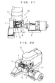
- FIG. 2 is a view showing a relation between a turret and a main spindle of the tool post seen from a direction indicated by an arrow A in FIG. 1
- FIG. 3 shows an internal configuration of an entire tool post by enlarging its longitudinal section taken along III-III line in FIG. 2 .
- a headstock 2 supporting a rotatable main spindle 3 is mounted on a headstock supporting part 1a of a bed 1.
- the headstock 2 can be moved in a Z-axis direction being orthogonal to the paper surface of by a not-shown drive mechanism.
- the main spindle 3 holds a workpiece W for machining using a chuck via a guide bush provided therein, and is rotated by a not-shown spindle motor.
- a rotation speed thereof can be varied from high speed to low speed.
- a tool post 10 Various types of tools to be used for processing the workpiece W are held by a tool post 10. All composing members of the tool post 10 are assembled in a fork-shaped turret housing 100, and in a hollow portion of the turret housing 100, two turrets 11 and 12 are arranged in upper and lower stages along an axis y-y in a Y-axis direction.
- each of the turrets 11 and 12 has the same regular quadranglar board shape in which respective corners are chamfered, tool attachment parts 11a and 12a are provided on respective surfaces of outer peripheral surfaces of the respective turrets 11 and 12 formed of four surfaces being mutually parallel or perpendicular, and each of arbitrary tools can be attached to the tool attachment parts 11a and 12a.
- FIG. 2 shows a state where the respective tool attachment parts 11a and 12a of the turrets 11 and 12 are in the same rotational position and are just overlapped with each other.
- all of the tool attachment parts 11a and 12a are supposed to be rotating tool attachment parts, and a rotating tool 15 such as a drill is attached to each of the rotating tool attachment parts.
- a rotating tool 15 such as a drill is attached to each of the rotating tool attachment parts.
- these respective rotating tools 15 differ in their diameters and their usage, and a thread-cutting rotating tool and the like are also included in the rotating tool 15.
- the turrets 11 and 12 capable of rotating around the axis y-y along the Y-axis are disposed along the axis y-y and each of which is dividedly rotated independently by separate turret driving motors 13 and 14 provided at the back of the turret housing 100. Further, all of the rotating tools 15 attached to the turrets 11 and 12 are rotationally driven by a common rotating tool driving motor 17. Details of these rotating mechanisms will be described later with reference to FIG. 3 .
- the turret housing 100 of the tool post 10 is attached to an X-axis carriage 20 by fiting a pair of sliders 18 fixedly provided to a side surface of the turret housing 100 with a slide rail 21 fixedly provided to a side surface of the X-axis carriage 20 so that the turret housing 100 can be moved in the Y-axis direction by a Y-axis motor 19 and a not-shown feed screw and nut.
- the X-axis carriage 20 is attached to a Z-axis carriage 30 by fiting a pair of sliders 22 fixedly provided to a bottom surface of the X-axis carriage 20 with a slide rail 31 fixedly provided to an upper surface of the Z-axis carriage 30 so that the X-axis carriage 20 can be moved in the X-axis direction by an X-axis motor 23 and a not-shown feed screw and nut.
- the Z-axis carriage 30 is attached to the bed 1 by fiting a pair of sliders 32 fixedly provided to a bottom surface of the Z-axis carriage 30 with a slide rail 1c fixedly provided to a slanted surface of a tool post supporting part 1b of the bed 1 so that the Z-axis carriage 30 can be moved in the Z-axis direction being orthogonal to the paper surface of FIG. 1 (direction indicated by an arrow Z in FIG. 2 ) by a Z-axis motor 33 provided at the back thereof and a not-shown feed screw and nut.
- the Z-axis is an axis being parallel to the main spindle 3 of the combined processing lathe, the X-axis is perpendicular to the Z-axis, and the Y-axis is an axis being orthogonal to a plane including the Z-axis and the X-axis. Therefore, the tool post 10 has three axes of X-axis, Y-axis and Z-axis each being orthogonal to one another, and can be moved three-dimensionally in a composite direction of moving directions along the respective axes.
- a rotary shaft 103 is rotatably supported by a fixed end plate 104 at a side of the arm portion 101 and a rotary end plate 105 composed of two members at a side of the arm portion 102 via ball bearings 106 and 107.
- a center axis of the rotary shaft 103 is the axis y-y.
- the turrets 11 and 12 are separately and rotatably arranged around the axis y-y in upper and lower stages through which the rotary shaft 103 penetrates.
- an upper turret rotary shaft 110 and a lower turret rotary shaft 120 respectively extending in the Z-axis direction being orthogonal to the paper surface of are rotatably inserted, and each of the turret rotary shafts is separately rotated by the turret driving motors 13 and 14 described in FIG. 1 .
- Worm gears 110g and 120g are respectively formed on the upper turret rotary shaft 110 and the lower turret rotary shaft 120.
- a cylindrical rotor 111 is provided in a rotatable manner inside the arm portion 101 via a cross roller bearing (roller bearing) 112 and oil seals 113, 114 and 115, and a worm wheel 111g formed on an outer periphery of the cylindrical rotor 111 rotates by engaging with the worm gear 110g of the upper turret rotary shaft 110.
- the cylindrical rotor 111 is integrally coupled to the upper stage of turret 11 in the rotational direction, so that the cylindrical rotor 111 and the turret 11 integrally rotate around the axis y-y.
- a cylindrical rotor 121 is provided in a rotatable manner inside the arm portion 102 via a cross roller bearing (roller bearing) 122 and oil seals 123 and 124, and a worm wheel 121g formed on an outer periphery of the cylindrical rotor 121 rotates by engaging with the worm gear 120g of the lower turret rotary shaft 120.
- the cylindrical rotor 121 is integrally coupled to the rotary end plate 105 and the lower stage of turret 12 in the rotational direction, so that the cylindrical rotor 121 and the turret 12 integrally rotate around the axis y-y.
- the turrets 11 and 12 are fitted via a ball bearing 108 so as to be relatively rotated with each other.
- each of the tool attachment parts 11 a and 12a is provided to the respective plane portions of the outer peripheral surfaces of the turrets 11 and 12, and in the illustrated example, each of the tool attachment parts 11a and 12a is a rotating tool attachment part. Accordingly, in the respective tool attachment parts 11 a and 12a, bevel gears 131 each provided with a shaft hole 131a for inserting the rotating tool 15 and having an integral shaft are inserted from inner peripheral surface sides of the turrets 11 and 12 in a rotatable manner via ball bearings 132.
- a bevel gear 135 engaging with all the bevel gears 131 in the upper stage of turret 11 and a bevel gear 136 engaging with all the bevel gears 131 in the lower stage of turret 12 are respectively spline-connected to the rotary shaft 103, in which they are biased and locked by springs at predetermined positions in a direction along the axis y-y.
- this tool post 10 With the use of this tool post 10, by rotating the upper turret rotary shaft 110 or the lower turret rotary shaft 120 using the turret driving motors 13 or 14 shown in FIG. 1 , it is possible to dividedly rotate (turn) the respective rotating tools 15 at desired positions by independently rotating the respective upper stage of turret 11 or the lower stage of turret 12 by an arbitrary rotation angle.
- the mechanism for dividedly rotating the turrets 11 and 12 independently using rotations of the upper turret rotary shaft 110 and the lower turret rotary shaft 120 via the worm gears 110g and 120g, the cylindrical rotor 111 having the worm wheel 111g, the cylindrical rotor 121 having the worm wheel 121g and the like, is the turret drive mechanism.
- the turret drive mechanism it is possible to control the dividedly rotated positions of the plurality of respective turrets 11 and 12 so that positions of the respective tool attachment parts 11 a and 12a in the dividedly rotated direction coincide with each other and the positions are mutually displaced by an arbitrary angle. Note that since it is possible to dividedly rotate the turret by drive-controlling the respective turrets 11 and 12, similar to the conventional turret type tool post, a detailed explanation regarding the above will be omitted.
- the combined processing lathe provided with the tool post 10 it is possible to perform the boring processing and the like on the workpiece W by selecting the rotating tool 15 of either of the turrets 11 and 12, which is, for example, the rotating tool 15 of the turret 11, and rotating it to the processing position, moving the tool post 10 in the composite direction of X-axis, Y-axis and Z-axis, positioning the rotating tool 15 with respect to the workpiece W held by the main spindle 3 shown in FIG. 1 and FIG. 2 , and rotating all of the tools including the rotating tool 15 by rotating the rotary shaft 103.
- FIG. 4 shows the workpiece processing step performed by a lathe such as disclosed in the aforementioned Patent Document 1 which is provided with a tool post with a single spindle on which a conventional tool magazine is mounted.
- a lathe such as disclosed in the aforementioned Patent Document 1 which is provided with a tool post with a single spindle on which a conventional tool magazine is mounted.
- the tool 1 is then automatically changed to the tool 2 to be used for the following processing by the tool changer, and the processing with the tool 2 is started by positioning and turning the tool 2. Therefore, it is necessary to provide three steps of unprocessing time between the processing with the tool 1 and the processing with the tool 2.
- FIG. 4 shows the workpiece processing step performed by a lathe such as disclosed in the aforementioned Patent Document 3 in which a conventional turret capable of attaching tools at a plurality of stages is provided.
- a lathe such as disclosed in the aforementioned Patent Document 3 in which a conventional turret capable of attaching tools at a plurality of stages is provided.
- the retreat operation of the tool post is conducted, and the tool 2 to be used for the following processing is then selected and positioned by the turret, to thereby start the processing with the tool 2. Therefore, it is still necessary to provide two steps of unprocessing time between the processing with the tool 1 and the processing with the tool 2.
- FIG. 4 shows the workpiece processing step performed by the aforementioned combined processing lathe of the present invention.
- the tool 2 to be used for the following processing is previously selected and an angle position thereof is previously decided, and when the processing with the tool 1 is completed, the processing with the tool 2 is started right after the positioning of the tool 2. Therefore, the unprocessing time between the processing with the tool 1 and the processing with the tool 2 is only the time required for positioning the tool 2.
- the tool post according to the invention and the combined processing lathe provided with the tool post are used, it is possible to minimize the unprocessing time by constantly minimizing the time for selecting tools performed by the tool post, which enables to largely reduce the processing time per one workpiece. Further, since it is possible to respectively and independently rotate (turn) the plurality of turrets by an arbitrary angle, the flexibility of processing is increased and a variety of processings can be realized, which will be described later.
- FIG. 5 to FIG. 8 In these drawings, only substantial parts of the turrets and the spindles holding workpieces to be processed are shown in plan views.
- Each of the turrets in the embodiment has a regular hexagonal shape and tools are respectively attached to six surfaces of an outer peripheral surface thereof, in which the same reference numerals 11 and 12 as in the aforementioned embodiment are used for the sake of convenience, and the turrets are set to be an upper turret 11 and a lower turret 12 by being distinguished into an upper stage and a lower stage.
- a drill 5 being a rotating tool and a cutting tool 6 being a turning tool are supposed to be used.
- the main spindle 3 supported by the headstock 2 is set to be a front spindle, and further, a back spindle 4 supported by a rear headstock (back spindle head) 8 is also used.
- FIG. 5 shows an example where the upper turret 11 and the lower turret 12 are dividedly rotated while positions of tool attachment parts of the upper turret 11 and the lower turret 12 are coincided with each other, in which the tools are radially arranged, when seen planarly, in a state of being vertically overlapped with each other with each 60 degree interval between the centers of the respective tools. Subsequently, the drill 5 of the upper turret 11 and the cutting tool 6 of the lower turret 12 are dividedly rotated to selected positions and faced to a workpiece W1 held by the front spindle 3.
- FIG. 6 shows an example where the upper turret 11 and the lower turret 12 are dividedly rotated while the positions of the tool attachment parts of the upper turret 11 and the lower turret 12 are shifted by 30 degrees to each other, in which the tools are radially arranged, when seen planarly, with each 30 degree interval between the centers of the respective tools.
- a certain drill 5 of the lower turret 12 is dividedly rotated to a selected position, and is faced to a workpiece W2 held by the back spindle 4 supported by the rear headstock 8 in a direction orthogonal to the workpiece W2.
- FIG. 8 shows an example where the upper turret 11 and the lower turret 12 are to be dividedly rotated while the positions of the tool attachment parts of the upper turret 11 and the lower turret 12 are shifted by 15 degrees to each other.
- the back spindle 4 follows the movement, and also makes the necessary movement for performing the diagonal boring processing on the workpiece W2.
- FIG. 9 to FIG. 22 various types of processings performed by another embodiment of the combined processing lathe according to the invention will be further described with reference to FIG. 9 to FIG. 22 .
- the same reference numerals are attached to the portions corresponding to those shown in the aforementioned respective drawings, even if the shapes are more or less different from each other.
- a drill 7 attached horizontally is also used for the rotating tools to be attached to the upper turret 11 and the lower turret 12.
- those represented by odd numerals are front views and those represented by even numerals are perspective views, and each pair of the drawings shows the same situations.
- the workpiece W1 held by the front spindle 3 is referred to as "front workpiece W1”
- the workpiece W2 held by the back spindle 4 is referred to as "rear workpiece W2".
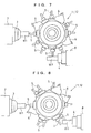
- FIG. 9 and FIG. 10 show states where edge boring processing on the front workpiece W1 using a certain drill 5 of the upper turret 11 of the tool post 10 and edge boring processing on the rear workpiece W2 using another drill 5 of the same upper turret 11 are simultaneously performed.
- FIG. 11 and FIG. 12 show states where the end face boring processing on the front workpiece W1 using the drill 5 of the upper turret 11 and the edge boring processing on the rear workpiece W2 using the drill 7 attached horizontally of the lower turret 12 are simultaneously performed.
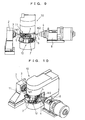
- FIG. 13 and FIG. 14 show states where the tool necessary for the following processing is indexed (dividedly rotated to the selected position) by the lower turret 12, while the end face boring processing on the front workpiece W1 is performed by the drill 5 of the upper turret 11.
- FIG. 15 and FIG. 16 show states where the turning on the rear workpiece W2 is started after the completion of the positioning of the cutting tool 6 of the lower turret turret 12 during when the end face boring processing on the front workpiece W1 is similarly performed by the drill 5 of the upper turret 11.
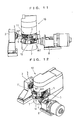
- FIG. 17 and FIG. 18 show states where the end face boring processing on the front workpiece W1 is finished from the above state, and the front workpiece W1 is retreated by the front spindle 3.
- FIG. 19 and FIG. 20 show states where the upper turret 11 is indexing, from that state, the tool to be used next.
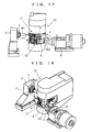
- FIG. 21 and FIG. 22 show states where the upper turret 11 completes the indexing of the drill 5 and starts the cross boring processing on the front workpiece W1 during when the turning on the rear workpiece W2 is performed by the cutting tool 6 of the lower turret 12.
- the plurality of stages of respective turrets can perform the cutting processing while turning at arbitrary angles. Accordingly, it becomes possible to perform boring processing using drills having different and arbitrary inclinations with respect to respective center lines of the workpiece held by the front spindle and the workpiece held by the back spindle, processing of grooves and surfaces with the use of milling cutters, simultaneous processings of turning using cutting tools and boring processing using drills, and the like, which results in largely extending the flexibility of processing.
- the headstock 2 and the front spindle 3 are replaced with a guide bush support table and a guide bush, and the front spindle supported by the headstock is provided at a position in the further rear of the guide bush support table (in the left direction in the drawings represented by odd numerals such as FIG. 9 ).
- the guide bush does not move in the Z-axis direction (in the left and right directions in the drawings represented by odd numerals such as FIG. 9 )
- the tool post 10 is only required to be designed to move in the Z-axis direction.
- the aforementioned movements along the X-axis, Y-axis and Z-axis are the relative movements between the tool post 10 and the workpiece W, it is only required that at least either one of the tool post 10 and the main spindle or the guide bush holding the workpiece W can be moved, with respect to the other one, in the directions of respective axes. Further, it is also possible that the tool post 10 is designed to rotate around the X-axis.
- FIG. 23 is a longitudinal sectional view showing an internal configuration of the tool post, and it corresponds to FIG. 3 showing the internal configuration of the aforementioned tool post. Therefore, the parts similar to the respective parts in FIG. 3 are designated by the same reference numerals, and a detailed explanation thereof will be omitted.
- a housing 500 of a tool post 50 corresponding to the turret housing 100 in FIG 3 also serves as a housing for two rotating tool driving motors 510 and 520 for rotationally driving the respective rotating tools 15 attached to the respective turrets 11 and 12.
- a rotary shaft corresponding to the rotary shaft 103 in FIG. 3 is composed of a first rotary shaft 511 having a pipe shape and being rotatably supported between the rotary end plate 105 and a bearing plate 501 fixed to an outer surface of the housing 500 (detailed illustration is omitted) and a second rotary shaft 521 formed of an outer cylinder rotatably engaged with an outer peripheral surface of the first rotary shaft 511 and supported by the fixed end plate 104 via the ball bearing 106.
- a belt pulley 512 is fixed to an upper end portion of the first rotary shaft 511, and a belt 514 is stretched between the belt pulley 512 and a belt pulley 513 fixed to a rotary shaft of the rotating tool driving motor 510.
- a belt pulley 522 is fixed to an upper end portion of the second rotary shaft 521, and a belt 524 is stretched between the belt pulley 522 and a belt pulley 523 fixed to a rotary shaft of the rotating tool driving motor 520. All of the above are provided inside a driving system cover 502.
- a bevel gear 515 engaging with all the bevel gears 131 in the lower stage of turret 12 and a bevel gear 525 engaging with all the bevel gears 131 in the upper stage of turret 11 are spline-connected to a lower end portion of the first rotary shaft 511 and to a lower end portion of the second rotary shaft 521, respectively, in which they are biased and locked by springs at predetermined positions in a direction along the axis y-y.
- the respective rotating tools 15 inserted into the tool attachment parts 11 a of the upper stage of turret 11 and the respective rotating tools 15 inserted into the tool attachment parts 12a of the lower stage of turret 12 can be respectively and independently rotationally driven when necessary.
- the tool post according to the invention which has been described above has the plurality of turrets independently provided on one moving tool post, so that it has both advantages of the turret and the flat turret, which are, regarding the tool arrangement on multiple faces as well as the arbitrary positioning of the turning angle of the tool, and a rapidity for selecting and changing the tool, respectively. Therefore, it becomes possible that while one of the turrets performs processing, the other turret performs a preparation operation for selecting the tool, and further, the time for selecting and switching tools being the unprocessing time can be largely reduced by a combination of selection/change of the tools from one of the tool posts to the other one realized by the movement of the entire tool post in the axial direction. In addition, it becomes possible to increase the number of tools that can be selected.
- the tools are simultaneously positioned at arbitrary angles with respect to each of workpieces held by a plurality of spindles, and the tools perform processing on each of the workpieces while respectively and independently moving at arbitrary angles.
- the turrets are provided in two stages, but, the example is not limited thereto, and if the turrets in three stages or more capable of being dividedly rotated respectively and independently are provided, it becomes possible to rapidly select a greater variety of different tools.
- the tool post having a tool magazine additionally provided therein it also becomes possible to automatically change the tool, during when one of the tool posts performs processing, as a preparation operation of the other turret turret, so that the number of tools which can be used largely increases, resulting that a combined processing lathe having a largely extended flexibility in comparison with any conventional lathes can be provided.
- the invention can be applied to a combined processing lathe which performs a plurality of different kinds of processings on a workpiece for machining, and to a tool post equipped in the lathe and selectably holding a plurality of tools to be used for the processings. Further, the invention can also be applied to various types of machine tools.
Landscapes
- Engineering & Computer Science (AREA)
- Mechanical Engineering (AREA)
- Turning (AREA)
- Cutting Tools, Boring Holders, And Turrets (AREA)
Abstract
Description
- The invention relates to a combined processing lathe (multiple turning center) performing a plurality of different kinds of processings (machinings) on a workpiece and a tool post being equipped in the lathe and selectably holding a plurality of tools used for the processings.
- A lathe generally performs processing by abutting a tool such as a cutting tool being a cutter against a workpiece for machining which is rotationally driven by a main spindle.
Further, a lathe which performs a plurality of different kinds of processings, namely, combined processing on a workpiece is also in wide use, and various types of lathes or machine tools such as disclosed in, for example,Patent Documents 1 to 5 are known. -
- Patent Document 1:
JP H11-138374 A - Patent Document 2:
JP H10-15702 A - Patent Document 3:
EP 1270145 A2 - Patent Document 4:
JP S62-236607 A - Patent Document 5:
JP H7-227704 A - A combined processing lathe disclosed in
Patent Document 1 is a lathe having a tool magazine holding a plurality of kinds of cutting tools mounted thereon, and capable of performing combined processing while successively changing the tool held by a tool spindle being a single spindle with the use of a tool changer in accordance with the processing contents. As a tool used in such a combined processing lathe, there are various types of tools such as "cutting tool (tool bit)" used for turning in which processing is performed without rotating the tool spindle, "drill" used by rotating the tool spindle, "milling cutter" which performs surface processing, and "grindstone tool" which performs grinding. - However, in such a combined processing lathe in which the tool held by the tool spindle being the single spindle is changed by the tool changer according to each processing content, although the flexibility regarding the number of tools and a processing method conducted by the combined processing lathe is high, since the tool has to be changed at every processing step in which a different tool is used, the time for changing tools, namely, an unprocessing time has to be provided, which brings a limitation to the reduction in the processing time per one workpiece.
- In order to enable to change the tools in such a lathe in a short period of time, a flat turret and a rotary turret (turning tool post) are used in a multifunction lathe disclosed in, for example,
Patent Document 2. The flat turret arranges a plurality of tools (cutters) linearly and in a comb-teeth shape, and by moving the tool post (tool bit) in the arranged direction, it can select either one of the tools attached to the tool post so as to correspond the tool to a workpiece for machining. - Meanwhile, the rotary turret arranges, on respective side surfaces of a rotatable turret having a polygonal column shape, each of tools (cutters) in a radial manner with respect to a rotary shaft, and by dividedly rotating the turret, it can select either one of the tools attached to the turret so as to correspond the tool to a workpiece for machining.
It is also conducted that the processing time is reduced by independently or simultaneously performing the processings with these two kinds of tool posts. - Since each the aforementioned flat turret and rotary turret can selectively attach the plurality of tools, if the plurality of tools used for the processings are attached to the respective turrets, there is no need to change the tools and the necessary tools can be selected in a short period of time, resulting that the processing time for the workpiece can be reduced.
Since the flat turret selects the tool by its linear movement, the selection speed thereof is fast, and when a tool used for an immediately preceding processing and a tool to be used for the following processing are adjacently attached, the tool to be used for the following processing can be selected in a quite short period of time. However, if the tools are attached separately in the vicinity of both end portions of the turret, there is a problem that a movement stroke becomes long and the selection time also becomes long. - Meanwhile, although it rather takes time for the rotary turret to dividedly rotate the turret, even if the tool used for the immediately preceding processing and the tool to be used for the following processing are attached in separate positions, by selecting the rotating direction, the difference in selection time does not become considerably large.
Accordingly, in a machine tool disclosed in, for instance,Patent Document 3, respective side surfaces of a tool post head corresponding to the turret are divided into a plurality of parts (hereinafter, referred to as "stage") having intervals therebetween in a direction along a rotary shaft of the tool post head, each stage has a different kind of tool attached thereto, and the tool post head can be integrally and linearly moved in the direction along the rotary shaft. - Therefore, the tool post head can select, same as the rotary turret, the tool attached to the same stage on the side surface by being dividedly rotated (turned) around the rotary shaft, and can select, same as the flat turret, either of the plurality of tools attached to the different stage on the same side surface of the tool post head by linearly moving in the direction along the rotary shaft.
- Specifically, the tool post with this structure has both functions of the rotary turret and the flat turret, and it can select, when the tool used for the immediately preceding processing and the tool to be used for the following processing are attached to the different stages on the same side surface of the tool post head, the tool to be used for the following processing in a quite short period of time only by linearly moving the tool post head in the direction of rotary shaft.
- However, if the tool to be used for the following processing is attached to the different stage at the different dividedly rotated position of the tool post head, there is a need that the tool post head is dividedly rotated as well as moved linearly. Accordingly, the time for selecting the tool, namely, the unprocessing time has to be provided, resulting that the reduction in the processing time per one workpiece cannot be fully realized. Further, since disposition angles of the tools are decided depending on the number of divisions of the side surfaces of the tool post head in its rotational direction, there are a lot of restrictions on flexibility of processing in such a case where, for example, processing on a workpiece held by a first spindle and processing on a workpiece held by a second spindle are simultaneously conducted, and the tool post cannot be used effectively, which also results in creating a problem when reducing the processing time per one workpiece.
- In addition, examples where a plurality of turrets are disposed in an automatic lathe while being shifted to the positions in a direction of rotary shaft thereof are also disclosed in
Patent Documents Patent Document 4, two turrets (rotary tables) are provided in which they can be independently rotated and one of them can be shifted in an axial direction with respect to the other one. Further, it is structured such that both the turrets are fixed, together with their cutters (tools), to fixed positions with respect to a housing during a cutting operation, and the respective turrets can be dividedly rotated independently during a change of cutters.
However, it is not possible to previously select, during when the processing is performed using the cutter (tool) of one of the turrets, a cutter (tool) to be used for the following processing by dividedly rotating the other turret. -
Patent Document 5 discloses that the number of usable tools is increased without enlarging turrets, by integrating two turres and disposing them in series in a state where they are shifted by predetermined angles in rotational directions thereof, and that rotating tools attached to either of the turrets can be rotated by one common driving shaft. - However, the turrets cannot be dividedly rotated separately and independently, so that also in this case, it is not possible to previously select, during when the processing is performed using the tool of one of the turrets, a tool to be used for the following processing by dividedly rotating the other turret.
Accordingly, each of these turrets cannot fully reduce the time taken for selecting the tools, namely, the unprocessing time, resulting that the reduction in the processing time per one workpiece cannot be fully realized. Further, there are a lot of restrictions on the flexibility of processing. - As described above, each of the conventional combined processing lathes cannot achieve a sufficient reduction in time for selecting the tools performed by its tool post and a sufficient flexibility of processing, so that there are limitations in reducing the processing time per one workpiece.
The invention has been made in view of such circumstances, and an object thereof is to enable to largely reduce a processing time per one workpiece by constantly minimizing the time for selecting tools performed by a tool post in a combined processing lathe to minimize an unprocessing time, as well as by lowering the restrictions on the flexibility of processing. - In order to achieve the aforementioned object, a tool post according to the invention is characterized in that it is provided with a plurality of turrets each capable of being rotated around a common axis and having a plurality of tool attachment parts on an outer peripheral surface thereof disposed along the axis, and separate turret drive mechanisms dividedly rotating each of the plurality of turrets.
- If the tool post has three axes of Z-axis being parallel to a main spindle of a combined processing lathe, X-axis being perpendicular to the Z-axis, and Y-axis being orthogonal to a plane including the Z-axis and the X-axis, the common axis may be an axis along the Y-axis.
- Each of the respective separate turret drive mechanisms may be provided with a turret rotary shaft rotated by a motor, and a gear mechanism transmitting a rotation of the turret rotary shaft to a corresponding turret.
Further, the respective separate turret drive mechanisms are preferably capable of controlling dividedly rotated positions of the plurality of respective turrets so that positions of the respective tool attachment parts in the dividedly rotated direction coincide with each other and the positions are mutually displaced by an arbitrary angle. - In these tool posts, at least one of the plurality of tool attachment parts of the plurality of respective turrets is a rotating tool attachment part, and a rotating tool drive mechanism rotating a plurality of rotating tools to be attached to the respective rotating tool attachment parts using a common rotary shaft can be provided.
Alternately, it is also possible to provide a rotating tool drive mechanism rotating the rotating tools to be attached to the respective rotating tool attachment parts of the plurality of respective turrets by each turret using separate rotary shafts driven by separate rotating tool driving motors. - Further, a combined processing lathe according to the invention is a combined processing lathe provided with a tool post having three axes of Z-axis being parallel to a main spindle, X-axis being perpendicular to the Z-axis, and Y-axis being orthogonal to a plane including the Z-axis and the X-axis, and the tool post being either of the aforementioned tool posts.
- A combined processing lathe provided with a tool post according to the invention can previously select, during when a workpiece is machined by a tool attached to one of a plurality of turrets of the tool post, a tool necessary for the following processing attached to another turret, and can move the tool necessary for the following processing attached to another turret to a processing position in a minimum period of time by linearly moving the tool post in a Y-axis direction right after the completion of the current processing, to thereby start the following processing.
Further, it also becomes possible to simultaneously conduct processings in such a manner that the processing is performed on a workpiece held by a first spindle using a tool held by a certain turret while the processing is performed on another workpiece held by a second spindle using atool 2 held by another turret. - In addition, each of the turrets can be turned at an arbitrary angle to perform processings, so that it also becomes possible to perform, on the workpiece held by the first spindle and the workpiece held by the second spindle, boring using drills having different and arbitrary inclinations with respect to center axes of the respective workpieces, processing of a groove and a surface with the use of milling, turning and boring, and the like, which results in largely extending the flexibility of processing.
Accordingly, it is possible to minimize the unprocessing time and to lower the restrictions on the flexibility of processing, which enables to remarkably reduce the processing time per one workpiece. -
-
FIG. 1 is a front view showing a schematic configuration of an entire combined processing lathe provided with a tool post being one embodiment of the invention; -
FIG. 2 is a view showing a relation between a turret and a main spindle of the tool post seen from a direction indicated by an arrow A inFIG. 1 ; -
FIG. 3 is a longitudinal sectional view of the tool post taken along III-III line inFIG. 2 ; -
FIGS. 4 is showing process charts drawing parallel between workpiece processing steps conducted by a conventional combined processing lathe and that conducted by the combined processing lathe according to the invention; -
FIG. 5 is substantial plan view showing a state before the processing using the combined processing lathe according to the invention; -
FIG. 6 is a substantial plan view showing a state where a front workpiece is being processed; -
FIG. 7 is a substantial plan view showing a state where the front workpiece and a rear workpiece are being simultaneously processed; -
FIG. 8 is a substantial plan view showing another state where the front workpiece and the rear workpiece are being simultaneously processed; -
FIG. 9 is a front view showing a state where end face boring processing on a front workpiece and end face boring processing on a rear workpiece are simultaneously performed by an upper turret of another embodiment of the combined processing lathe according to the invention; -
FIG. 10 is a perspective view ofFIG. 9 ; -
FIG. 11 is a front view showing a state where end face boring processing on the front workpiece using the upper turret and end face boring on the rear workpiece using a lower turret of the same embodiment are simultaneously performed; -
FIG. 12 is a perspective view ofFIG. 11 ; -
FIG. 13 is a front view showing a state where the lower turret of the same embodiment is being indexed; -
FIG. 14 is a perspective view ofFIG. 13 ; -
FIG. 15 is a front view showing a state where turning on the rear workpiece is performed after positioning the lower turret of the same embodiment; -
FIG. 16 is a perspective view ofFIG. 15 ; -
FIG. 17 is a front view showing a state where the front workpiece of the same embodiment is retreated; -
FIG. 18 is a perspective view ofFIG. 17 ; -
FIG. 19 is a front view showing a state where the upper turret of the same embodiment is being indexed; -
FIG. 20 is a perspective view ofFIG. 19 ; -
FIG. 21 is a front view showing a state where the upper turret of the same embodiment performs cross boring processing on the front workpiece; -
FIG. 22 is a perspective view ofFIG. 21 ; and -
FIG. 23 is a longitudinal sectional view showing an internal configuration of another embodiment of the tool post according to the invention. - 1: bed 2: headstock 3: main spindle (front spindle)
4: back spindle 5: drill (rotating tool)
6: cutting tool (turning tool or tool bit)
7: drill attached horizontally (rotating drill)
8: rear headstock (back spindle head)
10, 50:tool post 11, 12: turret
11a, 12a:tool attachment part 13, 14: turret driving motor
15: rotating tool (drill) 17: rotating tool driving motor
18, 22, 32: slider 19: Y-axis motor 20: X-axis carriage
21, 31, 1c: slide rail 23: X-axis motor
30: Z-axis carriage 33: Z-axis motor
100:turret housing 100a: hollow portion
101, 102: arm portion 103: rotary shaft (for rotating tool)
104: fixed end plate 105: rotary end plate
106, 107, 108, 132: ball bearing
110: upper turret rotary shaft 120: lower turret rotary shaft
110g, 120g:worm gear 111, 121: cylindrical rotor
111g, 121 g:worm wheel 112, 122: cross roller bearing
113, 114, 115, 123, 124: oil seal
131, 135, 136: bevel gear 501: bearing plate
510, 520: rotating tool driving motor 511: first rotary shaft
521: secondrotary shaft
514, 524:belt 515, 525: bevel gear - Hereinafter, preferred embodiments of the present invention will be described with reference to the attached drawings.
First, with reference toFIG. 1 to FIG. 3 , explanations will be made regarding a configuration example of a combined processing lathe according to the invention and a basic configuration example of a tool post according to the invention included in the combined processing lathe.
FIG. 1 is a schematic front view showing an entire configuration of the combined processing lathe, andFIG. 2 is a view showing a relation between a turret and a main spindle of the tool post seen from a direction indicated by an arrow A inFIG. 1 .FIG. 3 shows an internal configuration of an entire tool post by enlarging its longitudinal section taken along III-III line inFIG. 2 . - In
FIG. 1 , aheadstock 2 supporting a rotatablemain spindle 3 is mounted on aheadstock supporting part 1a of abed 1. Theheadstock 2 can be moved in a Z-axis direction being orthogonal to the paper surface of by a not-shown drive mechanism.
Further, themain spindle 3 holds a workpiece W for machining using a chuck via a guide bush provided therein, and is rotated by a not-shown spindle motor. A rotation speed thereof can be varied from high speed to low speed. - Various types of tools to be used for processing the workpiece W are held by a
tool post 10. All composing members of thetool post 10 are assembled in a fork-shapedturret housing 100, and in a hollow portion of theturret housing 100, twoturrets - In this example, each of the
turrets tool attachment parts respective turrets tool attachment parts FIG. 2 shows a state where the respectivetool attachment parts turrets - In this example, in order to simplify the explanation, all of the
tool attachment parts rotating tool 15 such as a drill is attached to each of the rotating tool attachment parts. Actually, these respectiverotating tools 15 differ in their diameters and their usage, and a thread-cutting rotating tool and the like are also included in therotating tool 15. - The
turrets turret driving motors turret housing 100. Further, all of therotating tools 15 attached to theturrets tool driving motor 17. Details of these rotating mechanisms will be described later with reference toFIG. 3 . - The
turret housing 100 of thetool post 10 is attached to anX-axis carriage 20 by fiting a pair ofsliders 18 fixedly provided to a side surface of theturret housing 100 with aslide rail 21 fixedly provided to a side surface of theX-axis carriage 20 so that theturret housing 100 can be moved in the Y-axis direction by a Y-axis motor 19 and a not-shown feed screw and nut.
TheX-axis carriage 20 is attached to a Z-axis carriage 30 by fiting a pair ofsliders 22 fixedly provided to a bottom surface of theX-axis carriage 20 with aslide rail 31 fixedly provided to an upper surface of the Z-axis carriage 30 so that theX-axis carriage 20 can be moved in the X-axis direction by anX-axis motor 23 and a not-shown feed screw and nut. - Further, the Z-
axis carriage 30 is attached to thebed 1 by fiting a pair ofsliders 32 fixedly provided to a bottom surface of the Z-axis carriage 30 with aslide rail 1c fixedly provided to a slanted surface of a toolpost supporting part 1b of thebed 1 so that the Z-axis carriage 30 can be moved in the Z-axis direction being orthogonal to the paper surface ofFIG. 1 (direction indicated by an arrow Z inFIG. 2 ) by a Z-axis motor 33 provided at the back thereof and a not-shown feed screw and nut. - The Z-axis is an axis being parallel to the
main spindle 3 of the combined processing lathe, the X-axis is perpendicular to the Z-axis, and the Y-axis is an axis being orthogonal to a plane including the Z-axis and the X-axis. Therefore, thetool post 10 has three axes of X-axis, Y-axis and Z-axis each being orthogonal to one another, and can be moved three-dimensionally in a composite direction of moving directions along the respective axes.
Note that it is possible to attach to the respectivetool attachment parts respective turrets - Next, an internal configuration of the
tool post 10 will be described with reference toFIG. 3 .
In the fork-shapedturret housing 100, there is formed ahollow portion 100a between upper andlower arm portions lower arm portions rotary shaft 103 is rotatably supported by afixed end plate 104 at a side of thearm portion 101 and arotary end plate 105 composed of two members at a side of thearm portion 102 viaball bearings rotary shaft 103 is the axis y-y. - Inside the
hollow portion 100a of theturret housing 100, theturrets rotary shaft 103 penetrates.
In the upper andlower arm portions rotary shaft 110 and a lowerturret rotary shaft 120 respectively extending in the Z-axis direction being orthogonal to the paper surface of are rotatably inserted, and each of the turret rotary shafts is separately rotated by theturret driving motors FIG. 1 .
Worm gears 110g and 120g are respectively formed on the upper turretrotary shaft 110 and the lowerturret rotary shaft 120. - Further, a
cylindrical rotor 111 is provided in a rotatable manner inside thearm portion 101 via a cross roller bearing (roller bearing) 112 andoil seals worm wheel 111g formed on an outer periphery of thecylindrical rotor 111 rotates by engaging with theworm gear 110g of the upper turretrotary shaft 110. Thecylindrical rotor 111 is integrally coupled to the upper stage ofturret 11 in the rotational direction, so that thecylindrical rotor 111 and theturret 11 integrally rotate around the axis y-y. - Meanwhile, a
cylindrical rotor 121 is provided in a rotatable manner inside thearm portion 102 via a cross roller bearing (roller bearing) 122 andoil seals worm wheel 121g formed on an outer periphery of thecylindrical rotor 121 rotates by engaging with theworm gear 120g of the lowerturret rotary shaft 120. Thecylindrical rotor 121 is integrally coupled to therotary end plate 105 and the lower stage ofturret 12 in the rotational direction, so that thecylindrical rotor 121 and theturret 12 integrally rotate around the axis y-y.
Theturrets ball bearing 108 so as to be relatively rotated with each other. - As described above, each of the
tool attachment parts turrets tool attachment parts tool attachment parts bevel gears 131 each provided with ashaft hole 131a for inserting the rotatingtool 15 and having an integral shaft are inserted from inner peripheral surface sides of theturrets ball bearings 132. - Further, a
bevel gear 135 engaging with all thebevel gears 131 in the upper stage ofturret 11 and abevel gear 136 engaging with all thebevel gears 131 in the lower stage ofturret 12 are respectively spline-connected to therotary shaft 103, in which they are biased and locked by springs at predetermined positions in a direction along the axis y-y. - Therefore, when the
rotary shaft 103 is rotated as indicated by an arrow B by the rotatingtool driving motor 17 shown inFIG. 1 , all thebevel gears 131 engaging with thebevel gears rotating tools 15 inserted into the respectivetool attachment parts turrets
If thetool attachment parts bevel gears 131 and theball bearings 132 are not provided to thetool attachment parts - With the use of this
tool post 10, by rotating the upper turretrotary shaft 110 or the lowerturret rotary shaft 120 using theturret driving motors FIG. 1 , it is possible to dividedly rotate (turn) the respectiverotating tools 15 at desired positions by independently rotating the respective upper stage ofturret 11 or the lower stage ofturret 12 by an arbitrary rotation angle. - As described above, the mechanism for dividedly rotating the
turrets rotary shaft 110 and the lowerturret rotary shaft 120 via the worm gears 110g and 120g, thecylindrical rotor 111 having theworm wheel 111g, thecylindrical rotor 121 having theworm wheel 121g and the like, is the turret drive mechanism. - According to the turret drive mechanism, it is possible to control the dividedly rotated positions of the plurality of
respective turrets tool attachment parts
Note that since it is possible to dividedly rotate the turret by drive-controlling therespective turrets - In the combined processing lathe provided with the
tool post 10, it is possible to perform the boring processing and the like on the workpiece W by selecting the rotatingtool 15 of either of theturrets tool 15 of theturret 11, and rotating it to the processing position, moving thetool post 10 in the composite direction of X-axis, Y-axis and Z-axis, positioning the rotatingtool 15 with respect to the workpiece W held by themain spindle 3 shown inFIG. 1 and FIG. 2 , and rotating all of the tools including therotating tool 15 by rotating therotary shaft 103. - If it is designed such that the
other turret 12 previously selects and rotates, during the processing, the rotatingtool 15 to be used for the following processing to the processing position, it is possible to start the following processing using the previously selected rotatingtool 15 only by moving thetool post 10 for a predetermined stroke in the Y-axis direction right after the completion of the current processing. - Here, by citing a workpiece processing step using two types of tools as an example, an explanation will be made by comparing a case where the workpiece processing step is conducted by a conventional combined processing lathe with a case where it is conducted by a combined processing lathe of the present invention, by using
FIG. 4 Regarding the indication of operating axes in the drawing, X, Y and Z represent operations along the aforementioned X-axis, Y-axis and Z-axis, B represents a turning operation of the tool post, and ATC represents an automatic tool changing operation performed by a tool changer, respectively. Note that "tool 1" and "tool 2" used here represent "tool to be used for a certain processing" and "tool to be used for the following processing". - (a) in
FIG. 4 shows the workpiece processing step performed by a lathe such as disclosed in theaforementioned Patent Document 1 which is provided with a tool post with a single spindle on which a conventional tool magazine is mounted. In this case, when the processing with thetool 1 is completed, the retreat operation of the tool post is conducted, thetool 1 is then automatically changed to thetool 2 to be used for the following processing by the tool changer, and the processing with thetool 2 is started by positioning and turning thetool 2. Therefore, it is necessary to provide three steps of unprocessing time between the processing with thetool 1 and the processing with thetool 2. - (b) in
FIG. 4 shows the workpiece processing step performed by a lathe such as disclosed in theaforementioned Patent Document 3 in which a conventional turret capable of attaching tools at a plurality of stages is provided. In this case, when the processing with thetool 1 is completed, the retreat operation of the tool post is conducted, and thetool 2 to be used for the following processing is then selected and positioned by the turret, to thereby start the processing with thetool 2.
Therefore, it is still necessary to provide two steps of unprocessing time between the processing with thetool 1 and the processing with thetool 2. - (c) in
FIG. 4 shows the workpiece processing step performed by the aforementioned combined processing lathe of the present invention. In this case, during the processing with thetool 1, thetool 2 to be used for the following processing is previously selected and an angle position thereof is previously decided, and when the processing with thetool 1 is completed, the processing with thetool 2 is started right after the positioning of thetool 2.
Therefore, the unprocessing time between the processing with thetool 1 and the processing with thetool 2 is only the time required for positioning thetool 2. - As described above, if the tool post according to the invention and the combined processing lathe provided with the tool post are used, it is possible to minimize the unprocessing time by constantly minimizing the time for selecting tools performed by the tool post, which enables to largely reduce the processing time per one workpiece.
Further, since it is possible to respectively and independently rotate (turn) the plurality of turrets by an arbitrary angle, the flexibility of processing is increased and a variety of processings can be realized, which will be described later. - Next, processing examples performed by using the combined processing lathe according to the invention will be described with reference to
FIG. 5 to FIG. 8 .
In these drawings, only substantial parts of the turrets and the spindles holding workpieces to be processed are shown in plan views. Each of the turrets in the embodiment has a regular hexagonal shape and tools are respectively attached to six surfaces of an outer peripheral surface thereof, in which thesame reference numerals upper turret 11 and alower turret 12 by being distinguished into an upper stage and a lower stage. To make the description concrete, for the tools, adrill 5 being a rotating tool and acutting tool 6 being a turning tool are supposed to be used. Themain spindle 3 supported by theheadstock 2 is set to be a front spindle, and further, aback spindle 4 supported by a rear headstock (back spindle head) 8 is also used. -
FIG. 5 shows an example where theupper turret 11 and thelower turret 12 are dividedly rotated while positions of tool attachment parts of theupper turret 11 and thelower turret 12 are coincided with each other, in which the tools are radially arranged, when seen planarly, in a state of being vertically overlapped with each other with each 60 degree interval between the centers of the respective tools. Subsequently, thedrill 5 of theupper turret 11 and thecutting tool 6 of thelower turret 12 are dividedly rotated to selected positions and faced to a workpiece W1 held by thefront spindle 3. Accordingly, similar to the flat turret, only by linearly moving the tool post in the Y-axis direction being orthogonal to the paper surface, it is possible to perform the cross boring processing using thedrill 5 or the turning using thecutting tool 6 on the workpiece W1 by positioning either one of the tools to the processing position. -
FIG. 6 shows an example where theupper turret 11 and thelower turret 12 are dividedly rotated while the positions of the tool attachment parts of theupper turret 11 and thelower turret 12 are shifted by 30 degrees to each other, in which the tools are radially arranged, when seen planarly, with each 30 degree interval between the centers of the respective tools. Subsequently, while the boring processing is performed on an end face of the workpiece W1 held by the main (front)spindle 3 using acertain drill 5 of theupper turret 11, acertain drill 5 of thelower turret 12 is dividedly rotated to a selected position, and is faced to a workpiece W2 held by theback spindle 4 supported by therear headstock 8 in a direction orthogonal to the workpiece W2. - When the
back spindle 4 is moved from this state in the X-axis direction shown inFIG. 1 , namely, to an upper direction inFIG. 6 , it is possible to simultaneously conduct the cross boring processing on the workpiece W2 held by theback spindle 4 while performing the boring processing on the end face of the workpiece W1 held by thefront spindle 3, as shown inFIG. 7 . At this time, when the tool post is moved in a direction of the end face of the workpiece W1 in accordance with the boring processing, theback spindle 4 follows the movement, and also makes the necessary movement for performing the cross boring processing on the workpiece W2. -
FIG. 8 shows an example where theupper turret 11 and thelower turret 12 are to be dividedly rotated while the positions of the tool attachment parts of theupper turret 11 and thelower turret 12 are shifted by 15 degrees to each other. In this case, similar to the example shown inFIG. 7 , it is possible to simultaneously conduct diagonal boring processing on the workpiece W2 held by theback spindle 4 using acertain drill 5 of thelower turret 12 while performing the boring processing on the end face of the workpiece W1 held by thefront spindle 3 using acertain drill 5 of theupper turret 11. Also at this time, when the tool post is moved in the direction of the end face of the workpiece W1 in accordance with the boring processing, theback spindle 4 follows the movement, and also makes the necessary movement for performing the diagonal boring processing on the workpiece W2. - Next, various types of processings performed by another embodiment of the combined processing lathe according to the invention will be further described with reference to
FIG. 9 to FIG. 22 . Also in these drawings, the same reference numerals are attached to the portions corresponding to those shown in the aforementioned respective drawings, even if the shapes are more or less different from each other. In addition, for the rotating tools to be attached to theupper turret 11 and thelower turret 12, adrill 7 attached horizontally is also used. Further, among these drawings, those represented by odd numerals are front views and those represented by even numerals are perspective views, and each pair of the drawings shows the same situations.
In the description hereinbelow, the workpiece W1 held by thefront spindle 3 is referred to as "front workpiece W1", and the workpiece W2 held by theback spindle 4 is referred to as "rear workpiece W2". -
FIG. 9 and FIG. 10 show states where edge boring processing on the front workpiece W1 using acertain drill 5 of theupper turret 11 of thetool post 10 and edge boring processing on the rear workpiece W2 using anotherdrill 5 of the sameupper turret 11 are simultaneously performed.
FIG. 11 and FIG. 12 show states where the end face boring processing on the front workpiece W1 using thedrill 5 of theupper turret 11 and the edge boring processing on the rear workpiece W2 using thedrill 7 attached horizontally of thelower turret 12 are simultaneously performed. -
FIG. 13 and FIG. 14 show states where the tool necessary for the following processing is indexed (dividedly rotated to the selected position) by thelower turret 12, while the end face boring processing on the front workpiece W1 is performed by thedrill 5 of theupper turret 11.
FIG. 15 and FIG. 16 show states where the turning on the rear workpiece W2 is started after the completion of the positioning of thecutting tool 6 of thelower turret turret 12 during when the end face boring processing on the front workpiece W1 is similarly performed by thedrill 5 of theupper turret 11. -
FIG. 17 and FIG. 18 show states where the end face boring processing on the front workpiece W1 is finished from the above state, and the front workpiece W1 is retreated by thefront spindle 3.
FIG. 19 and FIG. 20 show states where theupper turret 11 is indexing, from that state, the tool to be used next.
FIG. 21 and FIG. 22 show states where theupper turret 11 completes the indexing of thedrill 5 and starts the cross boring processing on the front workpiece W1 during when the turning on the rear workpiece W2 is performed by thecutting tool 6 of thelower turret 12. - As described above, in the tool post according to the invention, the plurality of stages of respective turrets can perform the cutting processing while turning at arbitrary angles. Accordingly, it becomes possible to perform boring processing using drills having different and arbitrary inclinations with respect to respective center lines of the workpiece held by the front spindle and the workpiece held by the back spindle, processing of grooves and surfaces with the use of milling cutters, simultaneous processings of turning using cutting tools and boring processing using drills, and the like, which results in largely extending the flexibility of processing.
- In the combined processing lathe shown in
FIG. 9 to FIG. 22 , it is also possible that theheadstock 2 and thefront spindle 3 are replaced with a guide bush support table and a guide bush, and the front spindle supported by the headstock is provided at a position in the further rear of the guide bush support table (in the left direction in the drawings represented by odd numerals such asFIG. 9 ). In such a case, since the guide bush does not move in the Z-axis direction (in the left and right directions in the drawings represented by odd numerals such asFIG. 9 ), thetool post 10 is only required to be designed to move in the Z-axis direction. - Since the aforementioned movements along the X-axis, Y-axis and Z-axis are the relative movements between the
tool post 10 and the workpiece W, it is only required that at least either one of thetool post 10 and the main spindle or the guide bush holding the workpiece W can be moved, with respect to the other one, in the directions of respective axes.
Further, it is also possible that thetool post 10 is designed to rotate around the X-axis. - Next, another embodiment of the tool post according to the invention will be described using
FIG. 23. FIG. 23 is a longitudinal sectional view showing an internal configuration of the tool post, and it corresponds toFIG. 3 showing the internal configuration of the aforementioned tool post. Therefore, the parts similar to the respective parts inFIG. 3 are designated by the same reference numerals, and a detailed explanation thereof will be omitted. However, ahousing 500 of atool post 50 corresponding to theturret housing 100 inFIG 3 also serves as a housing for two rotatingtool driving motors rotating tools 15 attached to therespective turrets - A rotary shaft corresponding to the
rotary shaft 103 inFIG. 3 is composed of a firstrotary shaft 511 having a pipe shape and being rotatably supported between therotary end plate 105 and abearing plate 501 fixed to an outer surface of the housing 500 (detailed illustration is omitted) and a secondrotary shaft 521 formed of an outer cylinder rotatably engaged with an outer peripheral surface of the firstrotary shaft 511 and supported by thefixed end plate 104 via theball bearing 106.
Abelt pulley 512 is fixed to an upper end portion of the firstrotary shaft 511, and abelt 514 is stretched between thebelt pulley 512 and abelt pulley 513 fixed to a rotary shaft of the rotatingtool driving motor 510. Further, abelt pulley 522 is fixed to an upper end portion of the secondrotary shaft 521, and abelt 524 is stretched between thebelt pulley 522 and abelt pulley 523 fixed to a rotary shaft of the rotatingtool driving motor 520.
All of the above are provided inside a drivingsystem cover 502. - Further, a
bevel gear 515 engaging with all thebevel gears 131 in the lower stage ofturret 12 and abevel gear 525 engaging with all thebevel gears 131 in the upper stage ofturret 11 are spline-connected to a lower end portion of the firstrotary shaft 511 and to a lower end portion of the secondrotary shaft 521, respectively, in which they are biased and locked by springs at predetermined positions in a direction along the axis y-y. - Therefore, when the first
rotary shaft 511 is rotated as indicated by the arrow B by the rotatingtool driving motor 510, all thebevel gears 131 engaging with thebevel gear 515 constituting the gear mechanism rotate, which results in rotating the respectiverotating tools 15 inserted into thetool attachment parts 12a of the lower stage ofturret 12. Further, when the secondrotary shaft 521 is rotated as indicated by the arrow B by the rotatingtool driving motor 520, all thebevel gears 131 engaging with thebevel gear 525 constituting the gear mechanism rotate, which results in rotating the respectiverotating tools 15 inserted into thetool attachment parts 11a of the upper stage ofturret 11. - As described above, in the
tool post 50, the respectiverotating tools 15 inserted into thetool attachment parts 11 a of the upper stage ofturret 11 and the respectiverotating tools 15 inserted into thetool attachment parts 12a of the lower stage ofturret 12 can be respectively and independently rotationally driven when necessary. - Note that also with the use of the
tool post 50, by rotating the upper turretrotary shaft 110 or the lowerturret rotary shaft 120 using each of the separate driving motors, it is possible to dividedly rotate (turn) the respectiverotating tools 15 at desired positions by independently rotating the respective upper stage ofturret 11 or the lower stage ofturret 12 by an arbitrary rotation angle, similar to the aforementioned embodiment. - The tool post according to the invention which has been described above has the plurality of turrets independently provided on one moving tool post, so that it has both advantages of the turret and the flat turret, which are, regarding the tool arrangement on multiple faces as well as the arbitrary positioning of the turning angle of the tool, and a rapidity for selecting and changing the tool, respectively.
Therefore, it becomes possible that while one of the turrets performs processing, the other turret performs a preparation operation for selecting the tool, and further, the time for selecting and switching tools being the unprocessing time can be largely reduced by a combination of selection/change of the tools from one of the tool posts to the other one realized by the movement of the entire tool post in the axial direction. In addition, it becomes possible to increase the number of tools that can be selected. - Further, it also becomes possible that the tools are simultaneously positioned at arbitrary angles with respect to each of workpieces held by a plurality of spindles, and the tools perform processing on each of the workpieces while respectively and independently moving at arbitrary angles.
In the aforementioned respective embodiments, an example where the turrets are provided in two stages has been explained, but, the example is not limited thereto, and if the turrets in three stages or more capable of being dividedly rotated respectively and independently are provided, it becomes possible to rapidly select a greater variety of different tools. - Further, if the tool post having a tool magazine additionally provided therein is used, it also becomes possible to automatically change the tool, during when one of the tool posts performs processing, as a preparation operation of the other turret turret, so that the number of tools which can be used largely increases, resulting that a combined processing lathe having a largely extended flexibility in comparison with any conventional lathes can be provided.
- The invention can be applied to a combined processing lathe which performs a plurality of different kinds of processings on a workpiece for machining, and to a tool post equipped in the lathe and selectably holding a plurality of tools to be used for the processings. Further, the invention can also be applied to various types of machine tools.
Claims (13)
- A tool post, comprising:a plurality of turrets each capable of being rotated around a common axis and having a plurality of tool attachment parts on an outer peripheral surface thereof disposed along the axis; andseparate turret drive mechanisms dividedly rotating each of said plurality of respective turrets.
- The tool post according to claim 1,
wherein said tool post has three axes of Z-axis being parallel to a main spindle of a combined processing lathe, X-axis being perpendicular to the Z-axis, and Y-axis being orthogonal to a plane including the Z-axis and the X-axis, and the common axis is an axis along the Y-axis. - The tool post according to claim 1,
wherein each of said separate turret drive mechanisms comprises a turret rotary shaft rotated by a motor and a gear mechanism transmitting a rotation of the turret rotary shaft to said turret corresponding to the turret rotary shaft. - The tool post according to claim 2,
wherein each of said respective separate turret drive mechanisms comprises a turret rotary shaft rotated by a motor and a gear mechanism transmitting a rotation of the turret rotary shaft to said turret corresponding to the turret rotary shaft. - The tool post according to any one of claims 1 to 4,
wherein each of said separate turret drive mechanisms can control dividedly rotated positions of said plurality of turrets respectively so that positions of said tool attachment parts in the dividedly rotated direction coincide with each other and the positions shifted by an arbitrary angle each other. - The tool post according to any one of claims 1 to 4,
wherein at least one of said plurality of tool attachment parts of each of said plurality of turrets is a rotating tool attachment part; and
further comprising a rotating tool drive mechanism rotating a plurality of rotating tools to be attached to each of the rotating tool attachment parts using a common rotary shaft. - The tool post according to any one of claims 1 to 4,
wherein at least one of said plurality of tool attachment parts of each of said plurality of turrets is a rotating tool attachment part; and
further comprising a rotating tool drive mechanism rotating rotating tools to be attached to said rotating tool attachment parts of said plurality of turrets by each turret using separate rotary shafts driven by separate rotating tool driving motors. - A combined processing lathe, comprising
a tool post having three axes of Z-axis being parallel to a main spindle, X-axis being perpendicular to the Z-axis, and Y-axis being orthogonal to a plane including the Z-axis and the X-axis,
wherein said tool post comprising:a plurality of turrets each capable of being rotated around an axis along the Y-axis and having a plurality of tool attachment parts on an outer peripheral surface thereof disposed along the axis; andseparate turret drive mechanisms dividedly rotating respectively each of said plurality of turrets. - The combined processing lathe according to claim 8,
wherein each of said separate turret drive mechanisms comprises a turret rotary shaft rotated respectively by a motor and a gear mechanism transmitting a rotation of the turret rotary shaft to said turret corresponding to the turret rotary shaft. - The combined processing lathe according to claim 8,
wherein each of said separate turret drive mechanisms can control dividedly rotated positions of said plurality of turrets respectively so that positions of said tool attachment parts in the dividedly rotated direction coincide with each other and the positions are shifted by an arbitrary angle each other. - The combined processing lathe according to claim 9,
wherein each of said separate turret drive mechanisms can control dividedly rotated positions of said plurality of turrets respectively so that positions of said tool attachment parts in the dividedly rotated direction coincide with each other and the positions are shifted by an arbitrary angle each other. - The combined processing lathe according to any one of claims 8 to 11,
wherein at least one of said plurality of tool attachment parts of each of said plurality of turrets is a rotating tool attachment part; and
wherein said tool post has a rotating tool drive mechanism rotating a plurality of rotating tools to be attached to each of the rotating tool attachment parts using a common rotary shaft. - The tool post according to any one of claims 8 to 11,
wherein at least one of said plurality of tool attachment parts of each of said plurality of respective turrets is a rotating tool attachment part; and
wherein said tool post has a rotating tool drive mechanism rotating a rotating tool to be attached to said rotating tool attachment part of said plurality of turrets respectively by each turret using separate rotary shafts driven by separate rotating tool driving motors.
Priority Applications (1)
| Application Number | Priority Date | Filing Date | Title |
|---|---|---|---|
| EP11192646.5A EP2428295B1 (en) | 2006-08-04 | 2007-08-01 | Tool post |
Applications Claiming Priority (2)
| Application Number | Priority Date | Filing Date | Title |
|---|---|---|---|
| JP2006213985 | 2006-08-04 | ||
| PCT/JP2007/065066 WO2008016076A1 (en) | 2006-08-04 | 2007-08-01 | Combined processing lathe and its tool post |
Related Child Applications (2)
| Application Number | Title | Priority Date | Filing Date |
|---|---|---|---|
| EP11192646.5A Division EP2428295B1 (en) | 2006-08-04 | 2007-08-01 | Tool post |
| EP11192646.5 Division-Into | 2011-12-08 |
Publications (3)
| Publication Number | Publication Date |
|---|---|
| EP2058071A1 true EP2058071A1 (en) | 2009-05-13 |
| EP2058071A4 EP2058071A4 (en) | 2009-07-22 |
| EP2058071B1 EP2058071B1 (en) | 2012-04-11 |
Family
ID=38997251
Family Applications (2)
| Application Number | Title | Priority Date | Filing Date |
|---|---|---|---|
| EP07791747A Not-in-force EP2058071B1 (en) | 2006-08-04 | 2007-08-01 | Tool post |
| EP11192646.5A Not-in-force EP2428295B1 (en) | 2006-08-04 | 2007-08-01 | Tool post |
Family Applications After (1)
| Application Number | Title | Priority Date | Filing Date |
|---|---|---|---|
| EP11192646.5A Not-in-force EP2428295B1 (en) | 2006-08-04 | 2007-08-01 | Tool post |
Country Status (7)
| Country | Link |
|---|---|
| US (1) | US8297158B2 (en) |
| EP (2) | EP2058071B1 (en) |
| JP (1) | JP5100652B2 (en) |
| KR (1) | KR101098690B1 (en) |
| CN (2) | CN103223504B (en) |
| ES (1) | ES2488622T3 (en) |
| WO (1) | WO2008016076A1 (en) |
Cited By (8)
| Publication number | Priority date | Publication date | Assignee | Title |
|---|---|---|---|---|
| EP2199012A2 (en) * | 2008-12-17 | 2010-06-23 | SMS Meer GmbH | Machine tool for processing a tubular workpiece |
| WO2012163699A1 (en) * | 2011-05-31 | 2012-12-06 | Gildemeister Italiana S.P.A. | Machine tool |
| WO2012163701A1 (en) * | 2011-05-31 | 2012-12-06 | Gildemeister Italiana S.P.A. | Machine tool |
| US9687912B2 (en) | 2011-05-31 | 2017-06-27 | Gildemeister Italiana S.P.A. | Tool carrier and machine tool having a tool carrier |
| EP3112060A4 (en) * | 2014-02-27 | 2017-12-13 | Murata Machinery, Ltd. | Machine tool |
| EP3257629A1 (en) * | 2016-06-15 | 2017-12-20 | WENDT GmbH | Grinding machine |
| EP3530386A1 (en) * | 2018-02-21 | 2019-08-28 | Tornos SA | Machining lathe with numerical control |
| EP3663025A4 (en) * | 2017-10-24 | 2021-04-28 | Star Micronics Co., Ltd. | Lathe with tool unit mounted thereto |
Families Citing this family (35)
| Publication number | Priority date | Publication date | Assignee | Title |
|---|---|---|---|---|
| JP2011079069A (en) * | 2009-10-02 | 2011-04-21 | Okuma Corp | Machine tool and method of working inner diameter |
| WO2011118338A1 (en) * | 2010-03-25 | 2011-09-29 | シチズンホールディングス株式会社 | Machine tool |
| JP2011235412A (en) * | 2010-05-12 | 2011-11-24 | Honda Motor Co Ltd | Clamping device |
| KR101726447B1 (en) * | 2011-01-21 | 2017-04-12 | 두산공작기계 주식회사 | A High-rigidity Multipurpose Manufacturing Device |
| DE102011076834A1 (en) * | 2011-05-31 | 2012-12-06 | Gildemeister Italiana S.P.A. | MACHINE TOOL |
| DE102012012331B4 (en) * | 2011-07-28 | 2016-03-03 | Emag Holding Gmbh | machine tool |
| JP5682966B2 (en) * | 2011-11-21 | 2015-03-11 | 旭精機工業株式会社 | Wire forming machine |
| JP5854811B2 (en) * | 2011-12-19 | 2016-02-09 | Dmg森精機株式会社 | Machine Tools |
| TWI555606B (en) * | 2012-03-26 | 2016-11-01 | Citizen Holdings Co Ltd | Working machine |
| JP5891107B2 (en) * | 2012-05-18 | 2016-03-22 | 株式会社ツガミ | Machine Tools |
| DE102012014747A1 (en) * | 2012-07-26 | 2014-01-30 | Winema Maschinenbau Gmbh | Rotary transfer machine |
| US9352396B2 (en) * | 2013-03-05 | 2016-05-31 | Oberg Industries | Lathe for machining a workpiece and related methods and toolholders |
| DE102013013276A1 (en) * | 2013-08-08 | 2015-02-12 | Liebherr-Verzahntechnik Gmbh | Machine tool and method for machining workpieces with at least two separate machining units |
| CN103706806B (en) * | 2013-12-13 | 2015-12-09 | 宁波海天精工股份有限公司 | The safety zone control method of boring cutter on a kind of lathe |
| US20160138299A1 (en) * | 2014-10-20 | 2016-05-19 | John Powers, III | Multiple driver head post driving system |
| EP3040145B1 (en) * | 2014-12-29 | 2018-04-04 | Freni Brembo S.p.A. | Milling method for making grooves along a cavity which extends in a workpiece |
| KR102324412B1 (en) * | 2015-03-09 | 2021-11-11 | 두산공작기계 주식회사 | Turret tool post and tool machine having the same |
| JP6656558B2 (en) * | 2015-11-30 | 2020-03-04 | 株式会社 神崎高級工機製作所 | Vertical lathe |
| ITUB20160244A1 (en) * | 2016-01-28 | 2017-07-28 | Tecprocess Sa | MACHINE TOOL. |
| CA2960613C (en) * | 2016-10-31 | 2019-02-26 | Yves Nelson | Gantry and quick connect mechanism for interchanging drilling and bolting assemblies and method of interchanging bolting assemblies |
| US10596691B2 (en) * | 2017-01-30 | 2020-03-24 | Stuart Topp | Devices and methods of using them to assemble two or more workpieces to each other |
| KR101954352B1 (en) * | 2017-04-05 | 2019-03-11 | 주식회사 금호엔티시 | multiple rotation convertible complex grinding apparatus |
| JP6829675B2 (en) * | 2017-10-23 | 2021-02-10 | Dmg森精機株式会社 | Tool holder for lathes and lathes equipped with this tool holder |
| JP7025631B2 (en) * | 2017-10-24 | 2022-02-25 | スター精密株式会社 | lathe |
| TWM561592U (en) * | 2018-01-29 | 2018-06-11 | Yu Zhu Neng | CNC Milling complex processing machine |
| EP3778079A4 (en) * | 2018-03-30 | 2021-12-22 | Citizen Watch Co., Ltd. | Machine tool |
| JP7140651B2 (en) * | 2018-11-28 | 2022-09-21 | シチズン時計株式会社 | Machine Tools |
| JP6778311B1 (en) * | 2019-11-01 | 2020-10-28 | Dmg森精機株式会社 | Tool post and machine tools |
| CN110756831A (en) * | 2019-11-26 | 2020-02-07 | 金华市彩橙机床有限公司 | Movable tool rest for machine tool |
| JP6828867B1 (en) * | 2020-04-17 | 2021-02-10 | 大久保歯車工業株式会社 | Automatic tool changer |
| CN111975070A (en) * | 2020-08-21 | 2020-11-24 | 新昌白云机床设备有限公司 | Bearing ring double-spindle three-tool-rest turning machine tool |
| US11833630B2 (en) | 2021-05-28 | 2023-12-05 | Yamazaki Mazak Corporation | Machine tool with removable workpiece support |
| KR102619995B1 (en) | 2021-12-27 | 2024-01-02 | (주)대성하이텍 | Turning center with ultrasonic vibration cutting structure |
| WO2024185584A1 (en) * | 2023-03-06 | 2024-09-12 | シチズン時計株式会社 | Rotating tool device, and machine tool |
| CN118438200B (en) * | 2024-07-04 | 2024-08-30 | 常州市特洛伊机电有限公司 | Drilling, tapping and milling intelligent lathe for spindle motor machining |
Citations (4)
| Publication number | Priority date | Publication date | Assignee | Title |
|---|---|---|---|---|
| GB1304245A (en) * | 1969-10-16 | 1973-01-24 | ||
| DE19528404A1 (en) * | 1995-08-02 | 1997-02-06 | Spinner Werkzeugmaschinenfabri | Dual workpiece machine tool with simultaneous swarf removal - has twin rotating workpiece holder and revolving tool holder rotating orthogonal to workpiece holder's axes |
| EP1452269A1 (en) * | 2003-02-25 | 2004-09-01 | Bacci Paolino Di Bacci Agostino | Toolhead for machine tools or work centers and machine comprising said head |
| US20040211301A1 (en) * | 2002-03-18 | 2004-10-28 | Takeo Kobayashi | Machine tool assembly |
Family Cites Families (24)
| Publication number | Priority date | Publication date | Assignee | Title |
|---|---|---|---|---|
| US2051720A (en) * | 1935-04-11 | 1936-08-18 | Kingsbury Edward Joslin | Composite machine tool for multiple operations |
| US3203071A (en) * | 1962-11-19 | 1965-08-31 | Hitachiseiki Kabushiki Kaisha | Dual turret heads type horizontal boring machine |
| JPS4946359B1 (en) * | 1969-10-15 | 1974-12-09 | ||
| US4182205A (en) * | 1978-04-27 | 1980-01-08 | Baker Gary L | Turret type metal working machine |
| JPS5916882B2 (en) * | 1978-05-04 | 1984-04-18 | 株式会社大隈「鉄」工所 | lathe turret |
| JPS56134101A (en) * | 1980-03-18 | 1981-10-20 | Ikegai Corp | Machine tool |
| DE3427245C2 (en) * | 1984-07-24 | 1986-07-17 | Maschinenfabrik Diedesheim GmbH, 6950 Mosbach | Machine tool |
| JPS62236607A (en) | 1986-04-03 | 1987-10-16 | 荘 国輝 | Turret with double carriage in automatic lathe |
| DE3633639A1 (en) * | 1986-10-03 | 1988-04-14 | Index Werke Kg Hahn & Tessky | LATHE |
| US5175914A (en) * | 1987-04-28 | 1993-01-05 | Yamazaki Mazak Corporation | Machine tool having dual spindles and tool rests |
| JPS6415702A (en) | 1987-07-10 | 1989-01-19 | Asahi Glass Co Ltd | Plastic lens with high refractive index |
| DE3734687C2 (en) * | 1987-10-14 | 1994-11-17 | Index Werke Kg Hahn & Tessky | Method for loading and unloading the main spindle of a lathe and lathe for performing this method |
| JPH01138374A (en) | 1987-11-25 | 1989-05-31 | Fuji Electric Co Ltd | Runaway speed limitter for movable vane waterwheel |
| JPH071201Y2 (en) * | 1989-02-23 | 1995-01-18 | 三菱自動車工業株式会社 | Lathe |
| US5127140A (en) * | 1989-12-18 | 1992-07-07 | Hitachi Seiki Co., Ltd. | Numerically-controlled lathe, numerically-controlled device therefor and processing procedure thereby |
| JPH07227704A (en) | 1994-02-16 | 1995-08-29 | Star Micronics Co Ltd | Turret type tool rest of automatic lathe |
| JPH1015702A (en) * | 1996-07-02 | 1998-01-20 | Star Micronics Co Ltd | Multifunctional lathe |
| WO1998057777A1 (en) * | 1997-06-17 | 1998-12-23 | Witzig & Frank Gmbh | Highly flexible machine tool |
| JPH11138374A (en) | 1997-09-04 | 1999-05-25 | Mori Seiki Co Ltd | Combined processing type lathe |
| DE10116994A1 (en) * | 2001-04-05 | 2002-10-17 | Index Werke Kg Hahn & Tessky | machine tool |
| EP1270145A3 (en) * | 2001-06-22 | 2004-02-11 | Traub Drehmaschinen GmbH | Machine tool with rotatable multi-tool holder |
| ITTO20010821A1 (en) * | 2001-08-21 | 2003-02-21 | O M V Ohg Venete S R L | NUMERIC CONTROL MILLING MACHINE. |
| DE10213777A1 (en) * | 2002-03-22 | 2003-10-16 | Traub Drehmaschinen Gmbh | machine tool |
| JP2006150574A (en) | 2004-12-01 | 2006-06-15 | Tong-Tai Machine & Tool Co Ltd | Machine tool for turning work |
-
2007
- 2007-08-01 KR KR1020097000870A patent/KR101098690B1/en active IP Right Grant
- 2007-08-01 US US12/376,218 patent/US8297158B2/en active Active
- 2007-08-01 CN CN201310130830.1A patent/CN103223504B/en not_active Expired - Fee Related
- 2007-08-01 CN CN2007800291611A patent/CN101500738B/en not_active Expired - Fee Related
- 2007-08-01 JP JP2008527770A patent/JP5100652B2/en not_active Expired - Fee Related
- 2007-08-01 EP EP07791747A patent/EP2058071B1/en not_active Not-in-force
- 2007-08-01 EP EP11192646.5A patent/EP2428295B1/en not_active Not-in-force
- 2007-08-01 ES ES11192646.5T patent/ES2488622T3/en active Active
- 2007-08-01 WO PCT/JP2007/065066 patent/WO2008016076A1/en active Application Filing
Patent Citations (4)
| Publication number | Priority date | Publication date | Assignee | Title |
|---|---|---|---|---|
| GB1304245A (en) * | 1969-10-16 | 1973-01-24 | ||
| DE19528404A1 (en) * | 1995-08-02 | 1997-02-06 | Spinner Werkzeugmaschinenfabri | Dual workpiece machine tool with simultaneous swarf removal - has twin rotating workpiece holder and revolving tool holder rotating orthogonal to workpiece holder's axes |
| US20040211301A1 (en) * | 2002-03-18 | 2004-10-28 | Takeo Kobayashi | Machine tool assembly |
| EP1452269A1 (en) * | 2003-02-25 | 2004-09-01 | Bacci Paolino Di Bacci Agostino | Toolhead for machine tools or work centers and machine comprising said head |
Non-Patent Citations (1)
| Title |
|---|
| See also references of WO2008016076A1 * |
Cited By (11)
| Publication number | Priority date | Publication date | Assignee | Title |
|---|---|---|---|---|
| EP2199012A2 (en) * | 2008-12-17 | 2010-06-23 | SMS Meer GmbH | Machine tool for processing a tubular workpiece |
| EP2199012A3 (en) * | 2008-12-17 | 2014-04-16 | SMS Meer GmbH | Machine tool for processing a tubular workpiece |
| WO2012163699A1 (en) * | 2011-05-31 | 2012-12-06 | Gildemeister Italiana S.P.A. | Machine tool |
| WO2012163701A1 (en) * | 2011-05-31 | 2012-12-06 | Gildemeister Italiana S.P.A. | Machine tool |
| US9126266B2 (en) | 2011-05-31 | 2015-09-08 | Gildemeister Italiana S.P.A. | Machine tool |
| US9687912B2 (en) | 2011-05-31 | 2017-06-27 | Gildemeister Italiana S.P.A. | Tool carrier and machine tool having a tool carrier |
| EP3112060A4 (en) * | 2014-02-27 | 2017-12-13 | Murata Machinery, Ltd. | Machine tool |
| EP3257629A1 (en) * | 2016-06-15 | 2017-12-20 | WENDT GmbH | Grinding machine |
| WO2017218318A1 (en) * | 2016-06-15 | 2017-12-21 | 3M Innovative Properties Company | Grinding machine |
| EP3663025A4 (en) * | 2017-10-24 | 2021-04-28 | Star Micronics Co., Ltd. | Lathe with tool unit mounted thereto |
| EP3530386A1 (en) * | 2018-02-21 | 2019-08-28 | Tornos SA | Machining lathe with numerical control |
Also Published As
| Publication number | Publication date |
|---|---|
| US8297158B2 (en) | 2012-10-30 |
| EP2428295A1 (en) | 2012-03-14 |
| ES2488622T3 (en) | 2014-08-28 |
| KR20090031905A (en) | 2009-03-30 |
| EP2058071B1 (en) | 2012-04-11 |
| KR101098690B1 (en) | 2011-12-23 |
| EP2428295B1 (en) | 2014-05-07 |
| CN103223504A (en) | 2013-07-31 |
| CN103223504B (en) | 2015-09-02 |
| JP5100652B2 (en) | 2012-12-19 |
| US20090308214A1 (en) | 2009-12-17 |
| JPWO2008016076A1 (en) | 2009-12-24 |
| EP2058071A4 (en) | 2009-07-22 |
| WO2008016076A1 (en) | 2008-02-07 |
| CN101500738B (en) | 2013-05-22 |
| CN101500738A (en) | 2009-08-05 |
Similar Documents
| Publication | Publication Date | Title |
|---|---|---|
| EP2428295B1 (en) | Tool post | |
| EP0375783B1 (en) | Machine tool | |
| US5020201A (en) | Machine tool | |
| US7117773B2 (en) | Turret for turret lathe | |
| EP2450134A1 (en) | Composite working lathe | |
| JP2001198702A (en) | Composite working machine | |
| US20200180035A1 (en) | Lathe | |
| US6640678B2 (en) | Lathe with two-opposed spindles | |
| CA3190394A1 (en) | Machine tool | |
| CN110605582A (en) | Double-spindle turning and milling composite machine tool | |
| US20200180036A1 (en) | Lathe with tool unit mounted thereto | |
| JP2007075922A (en) | Multispindle lathe | |
| JP4256098B2 (en) | 2-spindle facing lathe | |
| CN210818384U (en) | Double-spindle turning and milling composite machine tool | |
| JP2007061937A (en) | Two-spindle three-turret lathe | |
| JPH079201A (en) | Lathe and processing method by lathe | |
| US20190118268A1 (en) | Tool Holder for Lathe and Lathe Provided with the Tool Holder | |
| JP2003311501A (en) | Simultaneous machining method for opposed works on twin opposed-spindle lathe | |
| CN209614819U (en) | A kind of combined type multi-panel machining tool | |
| KR20230134806A (en) | Indexing device for machine tools | |
| JPH03234402A (en) | Lathe | |
| JP2936330B2 (en) | Tool stand for multi-axis machine tools | |
| JPS582762B2 (en) | NC lathe for complex machining | |
| JPH06126502A (en) | Machine tool | |
| JPH05345202A (en) | Composite nc lathe |
Legal Events
| Date | Code | Title | Description |
|---|---|---|---|
| PUAI | Public reference made under article 153(3) epc to a published international application that has entered the european phase |
Free format text: ORIGINAL CODE: 0009012 |
|
| 17P | Request for examination filed |
Effective date: 20090218 |
|
| AK | Designated contracting states |
Kind code of ref document: A1 Designated state(s): AT BE BG CH CY CZ DE DK EE ES FI FR GB GR HU IE IS IT LI LT LU LV MC MT NL PL PT RO SE SI SK TR |
|
| AX | Request for extension of the european patent |
Extension state: AL BA HR MK RS |
|
| A4 | Supplementary search report drawn up and despatched |
Effective date: 20090619 |
|
| RIC1 | Information provided on ipc code assigned before grant |
Ipc: B23B 3/16 20060101AFI20090615BHEP Ipc: B23Q 39/02 20060101ALI20090615BHEP |
|
| DAX | Request for extension of the european patent (deleted) | ||
| RBV | Designated contracting states (corrected) |
Designated state(s): CH DE ES FR IT LI |
|
| 17Q | First examination report despatched |
Effective date: 20091209 |
|
| REG | Reference to a national code |
Ref country code: DE Ref legal event code: R079 Ref document number: 602007021958 Country of ref document: DE Free format text: PREVIOUS MAIN CLASS: B23B0029240000 Ipc: B23B0003160000 |
|
| RIC1 | Information provided on ipc code assigned before grant |
Ipc: B23Q 16/02 20060101ALI20110808BHEP Ipc: B23Q 39/02 20060101ALI20110808BHEP Ipc: B23B 3/16 20060101AFI20110808BHEP |
|
| RTI1 | Title (correction) |
Free format text: TOOL POST |
|
| GRAP | Despatch of communication of intention to grant a patent |
Free format text: ORIGINAL CODE: EPIDOSNIGR1 |
|
| GRAS | Grant fee paid |
Free format text: ORIGINAL CODE: EPIDOSNIGR3 |
|
| GRAA | (expected) grant |
Free format text: ORIGINAL CODE: 0009210 |
|
| AK | Designated contracting states |
Kind code of ref document: B1 Designated state(s): CH DE ES FR IT LI |
|
| REG | Reference to a national code |
Ref country code: CH Ref legal event code: NV Representative=s name: NOVAGRAAF INTERNATIONAL SA Ref country code: CH Ref legal event code: EP |
|
| REG | Reference to a national code |
Ref country code: DE Ref legal event code: R096 Ref document number: 602007021958 Country of ref document: DE Effective date: 20120606 |
|
| PLBE | No opposition filed within time limit |
Free format text: ORIGINAL CODE: 0009261 |
|
| STAA | Information on the status of an ep patent application or granted ep patent |
Free format text: STATUS: NO OPPOSITION FILED WITHIN TIME LIMIT |
|
| 26N | No opposition filed |
Effective date: 20130114 |
|
| PG25 | Lapsed in a contracting state [announced via postgrant information from national office to epo] |
Ref country code: ES Free format text: LAPSE BECAUSE OF FAILURE TO SUBMIT A TRANSLATION OF THE DESCRIPTION OR TO PAY THE FEE WITHIN THE PRESCRIBED TIME-LIMIT Effective date: 20120722 |
|
| REG | Reference to a national code |
Ref country code: DE Ref legal event code: R097 Ref document number: 602007021958 Country of ref document: DE Effective date: 20130114 |
|
| REG | Reference to a national code |
Ref country code: FR Ref legal event code: ST Effective date: 20130430 |
|
| PG25 | Lapsed in a contracting state [announced via postgrant information from national office to epo] |
Ref country code: FR Free format text: LAPSE BECAUSE OF NON-PAYMENT OF DUE FEES Effective date: 20120831 |
|
| REG | Reference to a national code |
Ref country code: CH Ref legal event code: PFA Owner name: CITIZEN WATCH CO., LTD., JP Free format text: FORMER OWNER: CITIZEN HOLDINGS CO., LTD., JP |
|
| REG | Reference to a national code |
Ref country code: DE Ref legal event code: R082 Ref document number: 602007021958 Country of ref document: DE Representative=s name: PRUEFER & PARTNER MBB PATENTANWAELTE RECHTSANW, DE Ref country code: DE Ref legal event code: R081 Ref document number: 602007021958 Country of ref document: DE Owner name: CITIZEN WATCH CO., LTD., NISHITOKYO-SHI, JP Free format text: FORMER OWNER: CITIZEN HOLDINGS CO., LTD., TOKYO, JP |
|
| PGFP | Annual fee paid to national office [announced via postgrant information from national office to epo] |
Ref country code: IT Payment date: 20210712 Year of fee payment: 15 |
|
| PGFP | Annual fee paid to national office [announced via postgrant information from national office to epo] |
Ref country code: CH Payment date: 20210816 Year of fee payment: 15 Ref country code: DE Payment date: 20210630 Year of fee payment: 15 |
|
| REG | Reference to a national code |
Ref country code: DE Ref legal event code: R119 Ref document number: 602007021958 Country of ref document: DE |
|
| REG | Reference to a national code |
Ref country code: CH Ref legal event code: PL |
|
| PG25 | Lapsed in a contracting state [announced via postgrant information from national office to epo] |
Ref country code: LI Free format text: LAPSE BECAUSE OF NON-PAYMENT OF DUE FEES Effective date: 20220831 Ref country code: CH Free format text: LAPSE BECAUSE OF NON-PAYMENT OF DUE FEES Effective date: 20220831 |
|
| PG25 | Lapsed in a contracting state [announced via postgrant information from national office to epo] |
Ref country code: IT Free format text: LAPSE BECAUSE OF NON-PAYMENT OF DUE FEES Effective date: 20220801 Ref country code: DE Free format text: LAPSE BECAUSE OF NON-PAYMENT OF DUE FEES Effective date: 20230301 |