EP2057782B1 - Méthode d'attribution de ressources dans un réseau sans fil. - Google Patents
Méthode d'attribution de ressources dans un réseau sans fil. Download PDFInfo
- Publication number
- EP2057782B1 EP2057782B1 EP07851188A EP07851188A EP2057782B1 EP 2057782 B1 EP2057782 B1 EP 2057782B1 EP 07851188 A EP07851188 A EP 07851188A EP 07851188 A EP07851188 A EP 07851188A EP 2057782 B1 EP2057782 B1 EP 2057782B1
- Authority
- EP
- European Patent Office
- Prior art keywords
- message
- ctb
- channel resources
- channel
- coordinator
- Prior art date
- Legal status (The legal status is an assumption and is not a legal conclusion. Google has not performed a legal analysis and makes no representation as to the accuracy of the status listed.)
- Not-in-force
Links
Images


Classifications
-
- H—ELECTRICITY
- H04—ELECTRIC COMMUNICATION TECHNIQUE
- H04W—WIRELESS COMMUNICATION NETWORKS
- H04W72/00—Local resource management
- H04W72/20—Control channels or signalling for resource management
- H04W72/29—Control channels or signalling for resource management between an access point and the access point controlling device
-
- H—ELECTRICITY
- H04—ELECTRIC COMMUNICATION TECHNIQUE
- H04W—WIRELESS COMMUNICATION NETWORKS
- H04W72/00—Local resource management
- H04W72/20—Control channels or signalling for resource management
-
- H—ELECTRICITY
- H04—ELECTRIC COMMUNICATION TECHNIQUE
- H04W—WIRELESS COMMUNICATION NETWORKS
- H04W72/00—Local resource management
- H04W72/20—Control channels or signalling for resource management
- H04W72/23—Control channels or signalling for resource management in the downlink direction of a wireless link, i.e. towards a terminal
Definitions
- the present invention relates to a wireless network, and more particularly, to a method of allocating instant channel resources in a wireless network.
- a large-scaled network such as wire or wireless Internet, which connects the whole world, exists while a small-scaled wire or wireless network exists, which connects digital devices in limited places such as general homes or companies.
- various interfacing techniques have been also developed, which connect networks or devices with each other to perform communication between them.
- the reserved region is used to allow a device, to which a channel time is allocated by the coordinator in accordance with a channel time allocation request of the device, to transmit data to another device. Commands, data streams, asynchronous data, etc. can be transmitted through the reserved region.
- the unreserved region can be used to transmit control information, MAC command or asynchronous data between the coordinator and the device or between the devices. To avoid data collision between the devices in the unreserved region, a carrier sense multiple access (CSMA) mode or a slotted Aloha mode can be used.
- CSMA carrier sense multiple access
- the length and the number of reserved regions and unreserved regions in each superframe may depend on superframe and may be controlled by the coordinator.
- a specific device in the WVAN transmits a bandwidth request command to the coordinator so that the device can be allocated with channel resources for data transmission.
- the coordinator checks whether there are channel resources to be allocated to the device. If there are channel resources to be allocated to the device, the coordinator allocates the requested channel resources to the device. At this time, information of the channel resources allocated to the device, i.e., timing allocation information is forwarded to the devices within the WVAN through a beacon which will be transmitted later.
- the device in order that a random device is allocated with channel resources by requesting the coordinator of the channel resources and transmits data by using the allocated channel resources, the device should wait for the time to receive at least next beacon.
- This method of allocating channel resources may have a problem when instant data transmission is required.
- message exchange between two devices is instantly required, for example, if there is a previously set timing constraint to receive a response message to a message transmitted from a specific device to another device, a problem occurs in that the method of allocating channel resources according to the related art cannot fulfill the timing constraint.
- message exchange through a contention interval without allocation of channel resources may be considered.
- the contention based message exchange may cause collision between devices, a problem occurs in that it is impossible to ensure certainty in message transmission and reception.
- US 2005/0180385 A1 discloses a wireless media access method on a wireless network synchronized by a synchronizing signal broadcasted from a coordinator.
- priority is assigned to a plurality of devices interconnected over the wireless network for securing wireless resources in accordance with application characteristics of a packet to be transmitted, and if the devices request communication, dividing at least one slot within a superframe into a plurality of minislots.
- Minislots are then allocated to the devices, respectively, according to the priority, and information about the allocated minislots is inserted into the synchronizing signal. The information is then broadcast, thereby allowing each of the devices with the allocated minislots to exclusively use the allocated minislot for data communication.
- US 6,747,959 B1 relates to a protocol for voice-data integrated multiaccess to FDD (frequency division duplex) or TDD (time division duplex) local- or wide-area networks.
- FDD frequency division duplex
- TDD time division duplex
- the present invention is directed to a method of allocating channel resources in a wireless network, which substantially obviates one or more problems due to limitations and disadvantages of the related art.
- An object of the present invention is to provide a method of allocating instant channel resources if necessary in a state that channel resources are already allocated.
- Another object of the present invention is to provide a method of allocating channel resources in a wireless network, in which delay in message transmission between a wire network and a wireless network or between two devices can be avoided, whereby desirable communication can be performed.
- a method of allocating instant channel resources in a wireless network includes receiving channel resource allocation information of a specific superframe, which includes timing information of at least one reserved duration and at least one unreserved duration, from a coordinator of the wireless network, requesting the coordinator to allocate instant channel resources for an unreserved duration of the specific superframe identified by the channel resource allocation information, and receiving allocation information of the instant channel resources, which are allocated within the unreserved duration of the specific superframe, from the coordinator.
- a method of allocating instant channel resources in a coordinator of a wireless network includes broadcasting channel resource allocation information of a specific superframe to the wireless network, receiving a first message requesting allocation of instant channel resources for an unreserved duration of the specific superframe from a specific device of the wireless network, and broadcasting a second message to the wireless network, the second message announcing allocation of the instant channel resources within the unreserved duration of the specific superframe.
- a method of allocating instant channel resources in a coordinator of a wireless network includes receiving a first message requesting channel resources for transmission or reception of data from at least one device, broadcasting channel resource allocation information of a specific superframe, which is scheduled considering request of channel resources from the at least one device, to the wireless network through a beacon, receiving a second message from a specific device of the wireless network, the second message requesting allocation of instant channel resources for an unreserved duration of the specific superframe, and broadcasting a third message to the wireless network, the third message announcing allocation of the instant channel resources within the unreserved duration of the specific superframe.
- the wireless network is a wireless video area network (WVAN), and the channel resource allocation information is received by being included in a beacon.
- the instant channel resource allocation request can be performed through LRP channel of HRP channel and LRP channel which are used in the WVAN. Also, allocation information of the instant channel resources can be received through the LRP channel.
- the instant channel resources include a first channel resource for transmitting a specific message and a second channel resource for receiving a response message to the specific message.
- the first channel resource and the second channel resource are successively located or spaced apart from each other at a predetermined interval.
- a method of allocating instant channel resources in a wireless network which performs using a first channel and a second channel includes receiving a beacon, which includes channel resource allocation information of a specific superframe, from a coordinator of the wireless network through the second channel, transmitting a first message to the coordinator through the second channel, the first message requesting allocation of instant channel resources which include a predetermined bandwidth on at least one of the first channel and the second channel within an unreserved duration of the specific superframe identified by the channel resource allocation information, and receiving allocation information of instant channel resources, which are allocated within the unreserved duration of the specific superframe, from the coordinator through the second channel.
- a method of forwarding a message in a first interface device connected with a source device includes receiving a first message from the source device, the first message being transmitted to a destination device, allocating instant channel resources within a corresponding superframe from a coordinator to receive a response message to the first message from a second interface device connected with the destination device, transmitting a second message, which includes the first message, to the second interface device, receiving a response message to the second message from the second interface device through the allocated instant channel resources, and transmitting the response message to the first message to the source device.
- the allocating step of instant channel resources includes transmitting an instant channel resource allocation request message to the coordinator of the wireless network, and receiving an instant channel resource allocation announcement message from the coordinator.
- the second message is broadcasted to the wireless network.
- the instant channel resource allocation request message and the instant channel resource allocation announcement message are transmitted through the LRP channel.
- the first message is a consumer electronics control (CEC) message or a vendor specific data.
- the response message to the first message is an acknowledgement (ACK) signal.
- CEC consumer electronics control
- ACK acknowledgement
- the wireless network is a wireless video area network (WVAN), and the channel resource scheduling information is received by being included in a beacon.
- the instant channel resource allocation request and reception of the announcement message can be performed through the LRP channel.
- a WVAN is a wireless network configured between digital devices within a limited place, such as home, within 10m to ensure throughput of 4.5 Gbps or greater at a bandwidth of about 7 GHz, thereby supporting non-compression transmission of 1080p A/V streams.
- the WVAN supports physical layers, i.e., a high-rate physical (HRP) layer and a low-rate physical (LRP) layer.
- the HRP layer is a physical layer which supports a data transmission speed of 1Gb/s or greater while the LRP layer is a physical layer which supports a data transmission speed of several Mb/s.
- the HRP layer is highly directional, and is used to transmit isochronous data streams, asynchronous data, MAC command, and A/V control data through unicast connection.
- the LRP layer supports a directional or omni-directional mode, and is used to transmit a beacon, asynchronous data, and MAC command through unicast or broadcast.
- FIG. 3 illustrates a frequency band of HRP channels and LRP channels used in the WVAN.
- the HRP layer uses four channels of a bandwidth of 2.0 GHz in a band of 57-66 GHz, and the LRP uses three channels of a bandwidth of 92 MHz.
- the HRP channels and the LRP channels commonly use a frequency band and are used respectively by a time divisional multiplexing (TDMA) mode.
- TDMA time divisional multiplexing
- FIG. 4 illustrates an example of a structure of superframes used in the WVAN.
- each superframe includes a beacon region to which a beacon is transmitted, a reserved channel time block (CTB) region, and an unreserved channel time block region.
- the beacon is periodically transmitted by the coordinator to identify a start part of each superframe.
- the beacon includes scheduled timing information and management and control information of the WVAN.
- a specific device in the WVAN transmits a bandwidth request command to the coordinator so that the device can be allocated with channel resources for data transmission.
- the coordinator checks whether there are channel resources to be allocated to the device.
- the coordinator broadcasts information of channel resources allocated to the device, i.e., timing allocation information to the devices within the WVAN through a beacon which will be transmitted later.
- Each device can perform data exchange in the network through timing information and management/control information included in the beacon.
- the reserved CTB region is used to allow a device, to which a channel time is allocated by the coordinator in accordance with a channel time allocation request of the device, to transmit data to another device. Commands, data streams, asynchronous data, etc. can be transmitted through the reserved CTB region. If a specific device transmits data to another device through the reserved CTB region, the HRP channels can be used. If a device which receives data transmits an acknowledgement or negative acknowledgement (ACK/NACK) signal in response to the received data, the LRP channels can be used.
- ACK/NACK acknowledgement or negative acknowledgement
- the unreserved CTB region can be used to transmit control information, MAC command or asynchronous data between the coordinator and the device or between the devices.
- a carrier sense multiple access (CSMA) mode or a slotted Aloha mode can be used.
- CSMA carrier sense multiple access
- data can be transmitted through the LRP channels only. If there are provided a lot of commands or control information to be transmitted, a reserved region may be set in the LRP channels. The length and the number of reserved regions and unreserved regions in each superframe may depend on superframe and may be controlled by the coordinator.
- a contention-based control period (CBCP) may be located next to the beacon to transmit instant control/management message. The length of the CBCP is set so as not to exceed a given threshold value mMAXCBCPLen.
- FIG. 5 illustrates a structure of a protocol layer implemented in a device of the WVAN.
- a communication module of each device included in the WVAN can be divided into at least two layers depending on its function.
- the communication module includes a PHY layer 31 and a MAC layer 30.
- the communication module includes entities which manage each layer, wherein a MAC layer management entity (MLME) 300 manages the MAC layer and a PHY layer management entity (PLME) 310 manages the PHY layer.
- MLME MAC layer management entity
- PLME PHY layer management entity
- the communication module further includes a device management entity (DME) 320 which collects state information of each device and serves as a control interface between a host and a radio device.
- DME device management entity
- FIG. 6 illustrates an example of a structure of superframes according to the embodiment of the present invention.
- One superframe in the WVAN includes a beacon region, at least one reserved CTB region, and at least one unreserved CTB region.
- a superframe first scheduled by the coordinator includes two unreserved CTB regions (regions 'a' and 'c') and one reserved CTB region (region 'b').
- Detailed timing information of the unreserved CTB regions and the reserved CTB region is included in a beacon located at a starting part of the superframe.
- Each device within the WVAN transmits or receives required data in accordance with a contention mode through the reserved or unreserved CTB region allocated to itself, as described with reference to FIG. 4 , by using information included in the beacon.
- a specific device needs to be instantly allocated with a CTB within the superframe, it transmits an instant channel resource request message (INS_CTB_REQ Command) through the region ⁇ A' of FIG. 6 to request the coordinator instant channel resources, i.e., instant CTB within the unreserved CTB region.
- Table 1 illustrates an example of a format of the instant channel resource request command.
- 'instant channel resources' or 'instant CTB' are used to identify 'channel resources' and 'CTB' allocated from the coordinator through the beacon in accordance with a general method.
- a 'Command ID' field includes an identifier for identifying types of messages, and a 'Length' field includes length information of the other part of the instant channel resource request command.
- a 'Target ID' field includes an identifier of a device to which messages will be transmitted using requested channel resources, and a 'Source ID' field includes an identifier of a device which will transmit messages using requested channel resources. In case of the device which will transmit messages using the requested channel resources, the 'Source ID' field may include Broadcast ID before setup.
- a 'Usage Code' field includes an object of reservation of channel resources.
- a 'Start Limit' field includes timing constraint information to which channel resources should be allocated.
- the channel resources should be allocated within the range of the timing constraint included in the 'Start Limit' field.
- the 'Start Limit' field may include the fastest start timing or the latest start timing for allocating instant channel resources which are requested, or information related to both the fastest start timing and the latest start timing.
- the instant channel resources allocated in case of the latest start timing information should not be allocated to be started at a timing point later than that indicated by the start timing information within the superframe.
- An 'Instant CTB duration' field includes requested channel resources, i.e., length information of a CTB duration requested for message transmission.
- the coordinator checks whether the instant CTB can be allocated. If possible, the coordinator broadcasts an instant channel resource allocation announcement command (INS_CTB_ANC Command) from the region 'B' of FIG. 6 through the WVAN to notify allocation of the instant CTB.
- INS_CTB_ANC Command instant channel resource allocation announcement command
- Table 2 illustrates an example of a data format of the instant channel resource allocation announcement command.
- a 'Target ID' field and a 'Source ID' field include the same details as those of the 'Target ID' field and the 'Source ID' field in Table 1.
- a 'Start Offset' field includes start location information of a CTB which is allocated. For example, the 'Start Offset' field includes information as to whether a start point of an allocated CTB starts from a point indicating how long the point is located away from a specific reference point.
- An 'Instant CTB Duration' field includes information of channel resources which are allocated, i.e., duration length information of an instant CTB which is allocated.
- the devices within the WVAN which have received the instant channel resource allocation message, regard the allocated instant CTB region as the reserved region.
- the region 'C' of FIG. 6 is an instant CTB region allocated in accordance with the above procedure, and the specific device which has requested allocation of the instant channel resources can exchange data with another device through the instant CTB region.
- Allocation request and allocation announcement of the instant CTB can be performed through the LRP channels.
- the instant CTB region includes a bandwidth duration corresponding to any one of the LRP and HRP channels. In other words, a specific bandwidth of any one of the LRP channel and the HRP channel may be used as the instant CTB region, or a specific bandwidth of both of them may be used as the instant CTB region.
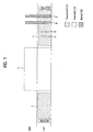
- FIG. 7 illustrates another example of a structure of superframes according to the embodiment of the present invention.
- the embodiment of FIG. 7 is different from that of FIG. 6 in that the instant CTB region is divided into two regions ('D' and 'E'). For example, if a specific device within the WVAN instantly should transmit a message to another device and receive a response message to the transmitted message and if there is a time constraint which requires that transmission of the message and reception of the response message should be performed within a previously set time period, one instant CTB region can be allocated for transmission of the message, and another instant CTB region can be allocated for reception of the response message.
- the device which requests allocation of the instant CTB can transmit the instant channel resource request command to the coordinator, wherein the instant channel resource request command includes information related to an allocation request of the two divided instant CTB regions and information related to the minimum and/or maximum space between the CTB regions in addition to the information included in Table 1.
- the coordinator After receiving the instant channel resource request command, the coordinator checks whether instant channel resources can be allocated. If possible, the coordinator broadcasts an instant channel resource allocation announcement command shown in Table 2 through the WVAN. At this time, the 'Start Offset' field of the instant channel resource allocation announcement command includes start location information of each instant CTB region, and the 'Instant CTB duration' field includes duration length information of each instant CTB region.
- FIG. 8 is a flow chart illustrating a method of allocating instant channel resources in accordance with the embodiment of the present invention.
- DEV 1 is allocated with instant channel resources to transmit a first message to DEV 2 and receives a second message from the DEV 2 in response to the first message.
- DME of the DEV 1 forwards MLME_INS_CTB.req primitive to MAC/MLME of the DEV 1 to command a request for allocation of instant channel resources [S81].
- the MAC/MLME of the DEV 1 transmits an instant channel resource request message (INS_CTB_REQ Command) to the coordinator to request allocation of the instant channel resources [S82].
- An example of the instant channel resource request message is the same as described with reference to Table 1.
- MAC/MLME of the coordinator forwards MLME_INS_CTB.ind primitive to DME of the coordinator to notify the fact that the instant channel resources have been requested from the DEV 1 [S83].
- the DME of the coordinator checks channel resources within a corresponding superframe to check whether instant channel resources of the DEV 1 can be allocated to the DEV 1 [S84]. If possible, the DME of the coordinator forwards MLME_INS_CTB.rsp primitive to the MAC/MLME of the coordinator to notify the fact that the instant channel resources can be allocated to the DEV 1 [S85].
- the MAC/MLME of the coordinator broadcasts an instant channel resource allocation announcement message (INS_CTB_ANC Command) to the wireless network to notify the fact that the instant channel resources have been allocated to the DEV 1 [S86].
- An example of the instant channel resource allocation announcement message is the same as described with reference to Table 2.
- the MAC/MLME of the DEV 1 forwards MLME_INS_CTB.cfm primitive to DME of the DEV 1 to notify the fact that the instant channel resources have been allocated [S87].
- the DME of the DEV 1 forwards the MLME_message.req primitive to the MAC/MLME of the DEV 1 to command the MAC/MLME of the DEV 1 to transmit the first message to the DEV 2 by using the allocated instant channel resources [S88].
- the MAC/MLME of the DEV 1 transmits the first message to the DEV 2 in a unicast or broadcast mode by using the allocated instant channel resources [S89].
- the MAC/MLME of the DEV 2 forwards MLME.message.ind primitive to the DME of the DEV 2 to notify reception of the first message [S90].
- the DME of the DEV 2 forwards the MLME-message.req primitive to the MAC/MLME of the DEV 2 to command the MAC/MLME of the DEV 2 to transmit the second message to the DEV 1 in response to the first message [S91].
- the MAC/MLME of the DEV 2 transmits the second message to the DEV 1 by using the allocated instant channel resources [S92].
- the MAC/MLME of the DEV 1 forwards the MLME.message.ind primitive to the DME of the DEV 1 to notify reception of the second message [S94].
- a given time constraint is set between the transmission time and the reception time of two primitives or a specific message and a response message to the specific message in accordance with the above method, it is possible to completely ensure a process within the time constraint through allocation of the instant channel resources.
- the transmission time and the reception time correspond to the time from a transmission timing point of MLME_INS_CTB.req primitive from to a reception timing point of MLME_message.ind primitive in the DME of the DEV 1, the time from a transmission timing point of MLME_message.req primitive to a reception timing point of MLME_message.ind primitive in the DME of the DEV 1, or the time from a transmission timing point of the first message to a reception timing point of the second message in the MAC/MLME of the DEV 1.
- 'mICRWT' means a maximum Instant CTB Request Waiting Time
- 'Instant CTB Duration' means a duration length of allocated instant channel resources.
- the 'Instant CTB Duration' is a value set so that the DME of the DEV 1 forwards MLME_message.req primitive to the MAC/MLME of the DEV 1 within the instant CTB duration and receives MLME_message.cfm primitive from the MAC/MLME of the DEV 1.
- a value obtained by adding 'mICRWT' to 'Instant CTB Duration' should be smaller than 'mAWT' which means the maximum waiting time.
- the first message may be transmitted and the second message in response to the first message is received for the 'Instant CTB duration.
- separate channel resources spaced apart from each other at a certain interval can be allocated for transmission of the first message and reception of the second message.
- the technical features of the present invention are applied to a method of transmitting and receiving a message for interfacing a high-definition multimedia interface (HDMI) network which is a kind of a wire network and a wireless video area network (WVAN) which is a kind of a wireless network (WPAN).
- HDMI high-definition multimedia interface
- WVAN wireless video area network
- WPAN wireless network
- the embodiment of the present invention relates to a method of transmitting a consumer electronics control (CEC) message from a specific device of the HDMI network to another device of the WVAN.
- CEC consumer electronics control
- the HDMI is a multimedia interface which can transmit full digital audio/video data, which are not compressed.
- the HDMI provides a wire interface between random audio/video devices such as set-top boxes, DVD players, monitors, and digital TVs.
- the HDMI supports multichannel digital audio on a single cable along with improved high definition video. In other words, it means that the HDMI can transmit every ATSC HDTV and also transmit eight-channel digital audio having a sufficient bandwidth.
- HDMI standard document, "High-Definition Multimedia Interface Specification Version 1.2a, Dec. 14, 2005” can be referred to so as to obtain the detailed description of the HDMI.
- FIG. 9 illustrates a schematic view according to the embodiment of the present invention.
- an HDMI device 40 and an interface device 50 are connected with each other by a connector 45.
- the interface device 50 receives A/V data streams and control information from the HDMI device 40 and transmits them to a specific device (not shown) of the WVAN through a wireless interface, so that the HDMI network is connected with the WVAN.
- the HDMI device 40 includes a main processor 41, an HDMI transmission chip 42, and a CEC signaling processor 43.
- the interface device 50 includes an HDMI reception chip 51, a format conversion processor 52, a MAC/PHY entity 53, and an RF module 54. Audio and video data and their assistant data transmitted from the HDMI transmission chip 42 of the HDMI device 40 are transmitted to the HDIM reception chip 51 of the interface device through three TMDS channels.
- a video pixel clock is transmitted through a clock channel of the TMDS channel, and the HDMI reception chip 51 uses the video pixel clock as a frequency reference signals for data recovery on the three TDMS data channels.
- the HDMI reception chip 51 forwards A/V streams transmitted from the HDMI transmission chip 42 to the MAC/PHY entity 53.
- the format conversion processor 52 converts a format of control information forwarded from the HDMI device 40 and forwards the converted format to the MAC/PHY entity 53.
- the MAC/PHY entity 53 processes the received data in accordance with a protocol, and the RF module 54 performs wireless signal processing, such as wireless modulation, up-converting, and signal amplification, for the received data, and transmits the processed data through an antenna (not shown).
- FIG. 10A illustrates a data format of the CEC message used in the HDMI system.
- a CEC protocol provides a high-level control function between all kinds of visual devices under a user environment. Examples of main CEC functions include one-touch play, system standby, one-touch record, and device menu control.
- the HDMI standard document, "High-Definition Multimedia Interface Specification Version 1.2a, Dec. 14, 2005" can be referred to so as to obtain the details of the CEC functions.
- an information bits field can include data, operation code, or address information.
- An end of message (EOM) bit indicates whether a corresponding bit corresponds to the end of a message, and an acknowledgement (ACK) bit is used to indicate whether a message receiving side has received data or header block.
- the ACK bit is set to ⁇ 1' by a source device which transmits the CEC message. If a destination device successfully receives the CEC message, ⁇ 0' is transmitted to the source device as an ACK signal.
- FIG. 10B illustrates a data format of a header block.
- the header block includes EOM bit, ACK bit, an 'Initiator' field (source ID) for identifying the source device which has transmitted the CEC message, and a 'Destination field' (destination ID) for identifying a destination device which should receive the CEC message.
- a starting bit is located at the front of the header block.
- the header block may be used as a 'Ping' message for checking whether other devices are in an active state.
- FIG. 11 illustrates a pulse format of each bit constituting the CEC message.
- (a) is a pulse format of ⁇ 0' bit
- (b) is a pulse format of ⁇ 1' bit.
- a pulse which expresses one bit has a length of 2.75ms.
- FIG. 12A illustrates a structure of a system according to the embodiment of the present invention.
- a source device 70 and a destination device 100 are interfaced with each other through a first interface device 80 and a second interface device 90.
- the first interface device 80 and the second interface device 100 may be implemented physically to form a single body with the source device 70 and the destination device 100, respectively.
- the first interface device 80 and the second interface device 100 may physically be separated from the source device 70 and the destination device 100, respectively, and may respectively be connected with the source device 70 and the destination device 100 through a connector.
- the first interface device 80 and the second interface device 100 perform communication through an air interface in accordance with WVAN protocol.
- the first interface device 80 includes a CEC interface (I/F) module 81, an upper layer entity 82, and a MAC/PHY layer entity 83.
- the second interface device 90 includes a CEC interface module 92, an upper layer entity 93, and a MAC/PHY layer entity 94.
- FIG. 12B illustrates a structure of another system according to the embodiment of the present invention.
- the system according to the embodiment of FIG 12B includes a source device 110, an interface device 120, and a destination device 130.
- the system according to the embodiment of FIG. 12B is different from that of FIG. 12A in that a second interface device (corresponding to 90 of FIG. 12A ) has been integrated into the destination device 130.
- a processor 131 of the destination device 130 implements the function of the CEC IF module 92 of the second interface device 90 in the system of FIG. 12A
- an upper layer entity 132 and a MAC/PHY entity of the destination device 130 integrally implement the functions of the upper layer entity 93 and the MAC/PHY entity 94 of the second interface device 90.
- FIG. 13 is a flow chart illustrating a procedure according to the embodiment of the present invention.
- the CEC message is transmitted from a source device DEV A to a destination device DEV B through the WVAN.
- the WVAN may include a coordinator, DEV 1, DEV 2, and other devices.
- the DEV 1 and the DEV 2 are interface devices, and receive the CEC message from the DEV A and forward the received CEC message to the DEV B through the WVAN.
- the DEV 1 and the DEV 2 forward ACK, which is transmitted from the DEV 2 in response to the CEC message, to the DEV A.
- the DEV 1 and the DEV 2 include a CEC I/F module.
- the DEV A corresponds to the source device 70
- the DEV B corresponds to the destination device 100
- the DEV 1 and the DEV 2 correspond to the first interface device 80 and the second interface device 90, respectively.
- the DEV A performs signaling of the CEC message to the CEC I/F module of the DEV 1 [S101 ⁇ S102]. If the DEV 1 receives the EOM bit of the CEC message, the DME of the DEV 2 forwards MLME_INS_CTB.req primitive to the MAC/MLME of the DEV 1 to request allocation of channel resources [S103].
- the DEV 2 If the DEV 1 transmits a predetermined message, which includes the CEC message, to the DEV 2, the DEV 2 requires resources to transmit a response message to the predetermined message, wherein the resources mean the channel resources. Since collision may occur if the DEV 2 transmits the response message in accordance with a contention based method without allocating separate channel resources, it is preferable that the DEV 2 is allocated with channel resources in advance. It is preferable that request and allocation of the channel resources are instantly performed within a corresponding superframe in accordance with the method described with reference to FIG. 7 or FIG. 8 . In other words, if the channel resources are allocated in accordance with a general method, an arrival time limit of ACK/NACK in response to the CEC message of 2.75ms may pass. Accordingly, allocation of channel resources is requested from the DEV 1 within a corresponding superframe, and the coordinator allocates channel resources, i.e., several unreserved CTBs within the corresponding superframe.
- the MAC/MLME of the DEV 1 transmits the instant channel resource request message (INS_CTB_REQ Command) shown in Table 1 to the MAC/MLME of the coordinator to request allocation of the channel resources [S104].
- the MAC/MLME of the coordinator forwards MLME_INS_CTB.ind primitive of the coordinator to notify that the channel resources have been requested from the DEV 1 [S105].
- the DME of the coordinator checks whether there are channel resources to be allocated [S106].
- the DME of the coordinator forwards MLME_INS_CTB.rsp primitive to the MAC/MLME of the coordinator to command the MAC/MLME of the coordinator to transmit information of channel resources, which are to be allocated, to the devices of the WVAN [S107].
- the MAC/MLME of the coordinator broadcasts the instant channel resource announcement message (INS_CTB_ANC Command) illustrated in Table 2 through the WVAN to notify the devices of the WVAN of information of the channel resources which are to be allocated [S108].
- the MAC/MLME of the devices of the WVAN including the DEV 1 and the DEV 2 forwards MLME_INS_CTB.cfm primitive to the DME to notify the fact of allocation of the channel resources [S109, S110].
- the DME of the DEV 1 forwards MLME_VD_CMD.req primitive to the MAC/MLME of the DEV 1 to command the MAC/MLME of the DEV 1 to transmit the CEC message to the DEV 2 [S111].
- the MAC/MLME of the DEV 1 constitutes a vendor specific request message (VD_CMD_REQ Command) which includes the CEC message, and broadcasts the vendor specific request message through the WVAN [S112].
- a 'Vendor OUI' field includes information of vendor OUI (Organizational Unique Identifier) information
- a 'Vendor Specification Data' field includes a message which is to be forwarded, i.e., the CEC message in FIG. 13 .
- the 'Vendor Specification Data' field may include a message or control information, which is not defined in WiHD standard document. At this time, data may be included in the 'Vendor Specification Data' byte unit.
- the CEC message includes 1 byte from bit 7 to bit 0, and then may additionally include bit information indicating EOM.
- the MAC/MLME of the DEV 1 can directly broadcast the message or control information, which is not defined by the WiHD standard document, i.e., the CEC message through the WVAN without including the message in the vendor specific request message (VD_CMD_REQ Command).
- VD_CMD_REQ Command vendor specific request message
- a packet may be constituted in a byte unit and then broadcasted.
- the MAC/MLME of the DEV 2 forwards MLME_VD_CMD.ind primitive to the DME of the DEV 2 to notify that the vendor specific request message has been received [S113].
- the CEC I/F module of the DEV 2 starts signaling of the CEC message included in the vendor specific request message to forward the CEC message to HDMI devices connected with the DEV 2 [S114].
- the DEV 2 performs an address resolution procedure after starting signaling of the CEC message [S115]. In other words, the DEV 2 checks, through the address resolution procedure, whether there is a destination device, i.e., DEV B, to which the CEC message is to be forwarded, among the HDMI devices connected with the DEV 2.
- the DEV 2 If the DME of the DEV 2 checks, through the address resolution procedure, that the DEV B has been connected with the DEV 2, the DEV 2 transmits ACK signal to the CEC message to the DEV 1 even before ending signaling of the CEC message.
- the MAC/MLME of the DEV 2 constitutes the vendor specific request response message (VD_CMD_RSP Command) which includes ACK in response to the CEC message, and transmits the vendor specific request response message to the DEV 1 [S117].
- the DME of the DEV 2 may end forwarding of the CEC message.
- the vendor specific request response message is transmitted through the channel resources allocated in the steps S104 ⁇ S108 for allocation of the channel resources.
- the MAC/MLME of the DEV 1 forwards MLME_VD_CMD.cfm primitive to the DME of the DEV 1 to notify the fact that the vendor specific request response message has been received [S118].
- the CEC I/F module of the DEV 1 transmits ACK to the DEV A based on the vendor specific request response message [S119].
- the DEV B After receiving the EOM bit of the CEC message [S120], the DEV B transmits ACK or NACK to the DEV 2 depending on the presence of receiving error [S121]. If the DEV 2 receives ACK from the DEV B, transmission of the CEC message ends. However, if the DEV 2 receives NACK, the DEV 2 should re-transmit the CEC message to the DEV B.
- 'mICRWT' means a maximum Instant CTB Request Waiting Time
- 'Instant CTB Duration' means a waiting time set such that the DME of the DEV 1 forwards MLME_VD_CMD.req primitive to the MAC/MLME of the DEV 1 and receives MLME_VD_CMD.cfm primitive from the MAC/MLME of the DEV 1.
- a value obtained by adding ⁇ mICRWT' to 'Instant CTB Duration' should be smaller than 'mAWT' which means the maximum ACK/NACK waiting time.
- the CEC message has ⁇ mAWT' of 2.75ms.
- the device may be replaced with a user device (or apparatus) or station
- the coordinator may be replaced with a coordinating apparatus (or control apparatus), a coordinating device (or control device), a coordinating station (or control station), or piconet coordinator (PNC).
- PNC piconet coordinator
- the embodiments according to the present invention may be implemented by various means, for example, hardware, firmware, software, or their combination. If the embodiment according to the present invention is implemented by hardware, it may be implemented by one or more application specific integrated circuits (ASICs), digital signal processors (DSPs), digital signal processing devices (DSPDs), programmable logic devices (PLDs), field programmable gate arrays (FPGAs), processors, controllers, microcontrollers, microprocessors, etc.
- ASICs application specific integrated circuits
- DSPs digital signal processors
- DSPDs digital signal processing devices
- PLDs programmable logic devices
- FPGAs field programmable gate arrays
- processors controllers, microcontrollers, microprocessors, etc.
- the embodiment according to the present invention is implemented by firmware or software, it may be implemented by a type of a module, a procedure, or a function, which performs functions or operations described as above.
- a software code may be stored in a memory unit and then may be driven by a processor.
- the memory unit may be located inside or outside the processor to transmit and receive data to and from the processor through various means which are well known.
- delay in message transmission between the wire network and the wireless network or between two devices can be avoided, whereby desirable communication can be performed.
- the present invention is applicable to a wireless network system.
Landscapes
- Engineering & Computer Science (AREA)
- Computer Networks & Wireless Communication (AREA)
- Signal Processing (AREA)
- Mobile Radio Communication Systems (AREA)
Claims (15)
- Procédé d'attribution de ressources de voies dans un premier dispositif d'un réseau sans fil, le procédé comprenant :la transmission (S82) d'un message demandant des ressources de voies du premier dispositif vers un coordinateur ; etla réception (S86) d'une information d'attribution de ressources de voies pour attribuer les ressources de voies par le premier dispositif en provenance du coordinateur,caractérisé en ce que les ressources de voies comprennent un premier bloc temporel de voie, appelé ci-après premier CTB, par lequel un premier message doit être transmis du premier dispositif à un deuxième dispositif, et un deuxième bloc temporel de voie, appelé ci-après deuxième CTB, par lequel un deuxième message, qui est une réponse au premier message, doit être reçu par le premier dispositif en provenance du deuxième dispositif, dans lequel le deuxième message doit être reçu au cours d'un intervalle de temps prédéterminé après la transmission du premier message.
- Procédé selon la revendication 1, dans lequel l'information d'attribution de ressources de voies est reçue en étant incluse dans une balise.
- Procédé selon la revendication 1, dans lequel le message demandant des ressources de voies comprend une information se rapportant à des espaces minimum et maximum entre le premier CTB et le deuxième CTB.
- Dispositif permettant l'attribution de ressources de voies dans un réseau sans fil, comprenant :un émetteur adapté pour transmettre (S82) un message servant à demander des ressources de voies à un coordinateur ; etun récepteur adapté pour recevoir (S86) une information d'attribution de ressources de voies pour attribuer les ressources de voies en provenance du coordinateur,caractérisé en ce que les ressources de voies comprennent un premier bloc temporel de voie, appelé ci-après premier CTB, par lequel un premier message doit être transmis du dispositif à un deuxième dispositif, et un deuxième bloc temporel de voie, appelé ci-après deuxième CTB, par lequel un deuxième message, qui est une réponse au premier message, doit être reçu du deuxième dispositif, dans lequel le deuxième message doit être reçu au cours d'un intervalle de temps prédéterminé après la transmission du premier message.
- Dispositif selon la revendication 4, dans lequel le message demandant des ressources de voies comprend une information se rapportant à des espaces minimum et maximum entre le premier CTB et le deuxième CTB.
- Dispositif selon la revendication 4, dans lequel le message demandant des ressources de voies comprend une information qui indique une heure de début à partir de laquelle le premier CTB doit être attribué.
- Procédé d'attribution de ressources de voies dans un coordinateur d'un réseau sans fil, le procédé comprenant :la réception (S82), par le coordinateur, d'un message demandant des ressources de voies provenant d'un premier dispositif ; etla transmission (S86) d'une information d'attribution de ressources de voies pour attribuer les ressources de voies du coordinateur vers le premier dispositif,caractérisé en ce que les ressources de voies comprennent un premier bloc temporel de voie, appelé ci-après premier CTB, par lequel un premier message doit être transmis du premier dispositif à un deuxième dispositif, et un deuxième bloc temporel de voie, appelé ci-après deuxième CTB, par lequel un deuxième message, qui est une réponse au premier message, doit être reçu par le premier dispositif en provenance du deuxième dispositif, dans lequel le deuxième message doit être reçu au cours d'un intervalle de temps prédéterminé après la transmission du premier message.
- Procédé selon la revendication 1 ou 7, dans lequel le premier CTB est adjacent au deuxième CTB.
- Procédé selon la revendication 1 ou 7, dans lequel le premier CTB et le deuxième CTB sont situés en deux positions qui sont séparées par un intervalle prédéterminé.
- Procédé selon la revendication 1 ou 7, dans lequel le message demandant des ressources de voies comprend une information qui indique une heure de début à partir de laquelle le premier CTB doit être attribué.
- Procédé selon la revendication 7, dans lequel l'information d'attribution de ressources de voies est transmise en étant incluse dans une balise.
- Procédé selon la revendication 7, dans lequel le message demandant des ressources de voies comprend une information se rapportant à des espaces minimum et maximum entre le premier CTB et le deuxième CTB.
- Coordinateur permettant d'attribuer des ressources de voies dans un réseau sans fil, le coordinateur comprenant :un récepteur adapté pour recevoir (S82) un message demandant des ressources de voies provenant d'un premier dispositif ; etun émetteur adapté pour transmettre (S86) une information d'attribution de ressources de voies pour attribuer les ressources de voies du coordinateur vers le premier dispositif,caractérisé en ce que les ressources de voies comprennent un premier bloc temporel de voie, appelé ci-après premier CTB, par lequel un premier message doit être transmis du premier dispositif à un deuxième dispositif, et un deuxième bloc temporel de voie, appelé ci-après deuxième CTB, par lequel un deuxième message, qui est une réponse au premier message, doit être reçu par le premier dispositif en provenance du deuxième dispositif, dans lequel le deuxième message doit être reçu au cours d'un intervalle de temps prédéterminé après la transmission du premier message.
- Coordinateur selon la revendication 13, dans lequel le message demandant des ressources de voies comprend une information qui indique une heure de début à partir de laquelle le premier CTB doit être attribué.
- Coordinateur selon la revendication 13, dans lequel le message demandant des ressources de voies comprend une information se rapportant à des espaces minimum et maximum entre le premier CTB et le deuxième CTB.
Applications Claiming Priority (3)
| Application Number | Priority Date | Filing Date | Title |
|---|---|---|---|
| US86829806P | 2006-12-01 | 2006-12-01 | |
| KR1020070014537A KR100914707B1 (ko) | 2006-12-01 | 2007-02-12 | 무선 네트워크에서의 긴급 채널 자원 할당 방법 및 디바이스 |
| PCT/KR2007/006197 WO2008066363A2 (fr) | 2006-12-01 | 2007-12-03 | Méthode d'attribution de ressources dans un réseau sans fil. |
Publications (3)
| Publication Number | Publication Date |
|---|---|
| EP2057782A2 EP2057782A2 (fr) | 2009-05-13 |
| EP2057782A4 EP2057782A4 (fr) | 2010-11-03 |
| EP2057782B1 true EP2057782B1 (fr) | 2012-03-07 |
Family
ID=39882801
Family Applications (1)
| Application Number | Title | Priority Date | Filing Date |
|---|---|---|---|
| EP07851188A Not-in-force EP2057782B1 (fr) | 2006-12-01 | 2007-12-03 | Méthode d'attribution de ressources dans un réseau sans fil. |
Country Status (7)
| Country | Link |
|---|---|
| US (3) | US8085723B2 (fr) |
| EP (1) | EP2057782B1 (fr) |
| JP (1) | JP5005034B2 (fr) |
| KR (1) | KR100914707B1 (fr) |
| CN (1) | CN101632257B (fr) |
| AT (1) | ATE548879T1 (fr) |
| WO (1) | WO2008066363A2 (fr) |
Families Citing this family (13)
| Publication number | Priority date | Publication date | Assignee | Title |
|---|---|---|---|---|
| US8214726B2 (en) * | 2006-05-19 | 2012-07-03 | Panasonic Corporation | Wireless communication device transmitting and receiving CEC messages of HDMI |
| US8824422B2 (en) | 2008-03-11 | 2014-09-02 | Intel Corporation | Techniques enabling dynamic bandwidth reservation in a wireless personal area network |
| JP5079872B2 (ja) * | 2008-03-27 | 2012-11-21 | パナソニック株式会社 | 無線通信装置 |
| WO2010143804A1 (fr) | 2009-06-09 | 2010-12-16 | Lg Electronics Inc. | Méthode et dispositif d'émission et réception de données dans un réseau sans fil |
| KR101567829B1 (ko) * | 2009-06-09 | 2015-11-20 | 엘지전자 주식회사 | 무선 네트워크에서의 데이터 전송 방법, 수신 방법 및 디바이스 |
| WO2010143791A1 (fr) * | 2009-06-09 | 2010-12-16 | Lg Electronics Inc. | Procédé d'attribution de ressources de canal et dispositifs dans des réseaux sans fil |
| WO2011034383A2 (fr) * | 2009-09-19 | 2011-03-24 | Samsung Electronics Co., Ltd. | Procédé et appareil d'allocation de canaux dans un système de communication par lumière visible |
| CN102196227A (zh) * | 2010-03-11 | 2011-09-21 | 株式会社日立制作所 | 视频数据处理装置 |
| KR101418991B1 (ko) * | 2010-11-22 | 2014-08-13 | 한국전자통신연구원 | Wave 기반의 차량 통신 시스템에서의 프레임 송신 장치 및 방법 |
| US9247395B2 (en) * | 2011-12-28 | 2016-01-26 | Industrial Technology Research Institute | Method and apparatus for broadcast assistance in direct communication system |
| TWI508569B (zh) * | 2012-09-14 | 2015-11-11 | Realtek Semiconductor Corp | 行動高畫質連結資料轉換器以及行動高畫質連結資料轉換方法 |
| CN107071907B (zh) * | 2016-12-29 | 2019-01-04 | 展讯通信(上海)有限公司 | 物理资源的配置方法及用户终端 |
| CN112135268B (zh) * | 2020-09-28 | 2023-11-14 | 奇点新源国际技术开发(北京)有限公司 | 无线组网系统的数据传输方法及无线组网系统 |
Family Cites Families (22)
| Publication number | Priority date | Publication date | Assignee | Title |
|---|---|---|---|---|
| EP0841763B1 (fr) * | 1996-10-25 | 2003-12-10 | Nokia Corporation | Procédé de contrôle de ressources radio |
| US6747959B1 (en) * | 1998-10-07 | 2004-06-08 | At&T Corp. | Voice data integrated mulitaccess by self-reservation and blocked binary tree resolution |
| US6738363B1 (en) * | 1999-11-05 | 2004-05-18 | Nortel Networks Limited | Method and apparatus for scheduling call admission control in satellite and wireless networks |
| US7280518B2 (en) * | 2001-10-03 | 2007-10-09 | Freescale Semiconductor, Inc. | Method of operating a media access controller |
| JP3995460B2 (ja) | 2001-12-11 | 2007-10-24 | 三洋電機株式会社 | タイムスロット割当装置 |
| KR100999094B1 (ko) * | 2003-06-27 | 2010-12-07 | 삼성전자주식회사 | 시분할 방식의 무선랜 통신방법 및 시스템 |
| KR100552484B1 (ko) * | 2004-02-13 | 2006-02-15 | 삼성전자주식회사 | 무선매체 접근방법 |
| KR100675382B1 (ko) * | 2004-05-06 | 2007-01-29 | 삼성전자주식회사 | 분산화 개인용무선네트워크의 매체접근제어방법, 채널타임예약 시스템 및 그 방법 |
| BRPI0515013A (pt) | 2004-08-12 | 2008-07-01 | Interdigital Tech Corp | método e sistema de controle de acesso a meio de comunicação sem fio |
| KR100810225B1 (ko) * | 2005-06-27 | 2008-03-07 | 삼성전자주식회사 | 다중채널 무선통신 시스템에서 데이터 패킷 전송을 위한스케줄링 장치 및 방법 |
| EP1938624A4 (fr) | 2005-10-21 | 2009-10-28 | Amimon Ltd | Appareil et procédé pour une transmission sans fil d'une vidéo non compressée |
| KR100791300B1 (ko) * | 2006-04-21 | 2008-01-04 | 삼성전자주식회사 | 무선 네트워크 시스템 및 상기 무선 네트워크상에서데이터를 송수신하는 방법 |
| US8583132B2 (en) | 2006-05-18 | 2013-11-12 | Qualcomm Incorporated | Efficient channel structure for a wireless communication system |
| KR100871854B1 (ko) * | 2006-06-05 | 2008-12-03 | 삼성전자주식회사 | 비동기 데이터 전송을 위한 채널 할당 관리 방법, 비동기데이터 전송 방법 및 상기 방법을 이용하는 장치 |
| KR101330633B1 (ko) * | 2006-06-08 | 2013-11-18 | 삼성전자주식회사 | 무선 통신 방법 및 장치 |
| KR101299732B1 (ko) * | 2006-07-14 | 2013-09-16 | 삼성전자주식회사 | 고주파 무선 대역에서의 무선 통신 방법 및 장치 |
| KR20080008196A (ko) * | 2006-07-18 | 2008-01-23 | 삼성전자주식회사 | 무선 네트워크 시스템 및 상기 무선 네트워크상에서데이터를 송수신하는 방법 |
| US20080031136A1 (en) * | 2006-08-07 | 2008-02-07 | Gavette Sherman L | Round trip time (rtt) proximity detection testing |
| KR101399361B1 (ko) * | 2006-08-25 | 2014-05-26 | 삼성전자주식회사 | 무선 통신 방법 및 장치 |
| US7843848B2 (en) * | 2006-10-31 | 2010-11-30 | Freescale Semiconductor, Inc. | Methods and apparatus for round trip time measurements |
| WO2008090980A1 (fr) * | 2007-01-25 | 2008-07-31 | Panasonic Corporation | Procédé de mesure du temps de transmission aller-retour des paquets |
| US7948961B2 (en) * | 2007-01-26 | 2011-05-24 | Sibeam, Inc. | Wireless proximity estimation |
-
2007
- 2007-02-12 KR KR1020070014537A patent/KR100914707B1/ko active IP Right Grant
- 2007-12-03 CN CN2007800444763A patent/CN101632257B/zh active Active
- 2007-12-03 WO PCT/KR2007/006197 patent/WO2008066363A2/fr active Application Filing
- 2007-12-03 US US12/377,378 patent/US8085723B2/en active Active
- 2007-12-03 EP EP07851188A patent/EP2057782B1/fr not_active Not-in-force
- 2007-12-03 AT AT07851188T patent/ATE548879T1/de active
- 2007-12-03 JP JP2009526550A patent/JP5005034B2/ja active Active
-
2011
- 2011-11-14 US US13/296,171 patent/US9332538B2/en active Active
-
2014
- 2014-09-15 US US14/486,705 patent/US9585137B2/en active Active
Also Published As
| Publication number | Publication date |
|---|---|
| US20100220669A1 (en) | 2010-09-02 |
| KR20080072484A (ko) | 2008-08-06 |
| WO2008066363A2 (fr) | 2008-06-05 |
| CN101632257B (zh) | 2012-07-18 |
| US9585137B2 (en) | 2017-02-28 |
| US20120057556A1 (en) | 2012-03-08 |
| US9332538B2 (en) | 2016-05-03 |
| ATE548879T1 (de) | 2012-03-15 |
| JP2010505290A (ja) | 2010-02-18 |
| EP2057782A2 (fr) | 2009-05-13 |
| US20150003387A1 (en) | 2015-01-01 |
| JP5005034B2 (ja) | 2012-08-22 |
| EP2057782A4 (fr) | 2010-11-03 |
| KR100914707B1 (ko) | 2009-08-28 |
| CN101632257A (zh) | 2010-01-20 |
| WO2008066363A3 (fr) | 2009-09-11 |
| US8085723B2 (en) | 2011-12-27 |
Similar Documents
| Publication | Publication Date | Title |
|---|---|---|
| EP2057782B1 (fr) | Méthode d'attribution de ressources dans un réseau sans fil. | |
| US8031666B2 (en) | Method for transmitting a data packet and a method of allocating a channel in a wireless network | |
| US7920540B2 (en) | Method and system for reliable broadcast or multicast communication in wireless networks | |
| EP2025118B1 (fr) | Procede de gestion d'attribution de canal pour transferer des donnees asynchrones, procede de transfert de donnees asynchrones, et apparail correspondant | |
| US7925269B2 (en) | Method and system for establishing a channel for a wireless video area network | |
| US8700064B2 (en) | Method and system for device discovery in a wireless video area network | |
| US8325686B2 (en) | Method and system for channel time allocation and access control in wireless network for high-definition video transmission | |
| EP2422578B1 (fr) | Procédé destiné à échanger des messages et système correspondant | |
| US9167562B2 (en) | Method of channel resource allocation and devices in wireless networks |
Legal Events
| Date | Code | Title | Description |
|---|---|---|---|
| PUAI | Public reference made under article 153(3) epc to a published international application that has entered the european phase |
Free format text: ORIGINAL CODE: 0009012 |
|
| 17P | Request for examination filed |
Effective date: 20090212 |
|
| AK | Designated contracting states |
Kind code of ref document: A2 Designated state(s): AT BE BG CH CY CZ DE DK EE ES FI FR GB GR HU IE IS IT LI LT LU LV MC MT NL PL PT RO SE SI SK TR |
|
| AX | Request for extension of the european patent |
Extension state: AL BA HR MK RS |
|
| R17D | Deferred search report published (corrected) |
Effective date: 20090911 |
|
| DAX | Request for extension of the european patent (deleted) | ||
| A4 | Supplementary search report drawn up and despatched |
Effective date: 20101005 |
|
| REG | Reference to a national code |
Ref country code: DE Ref legal event code: R079 Ref document number: 602007021228 Country of ref document: DE Free format text: PREVIOUS MAIN CLASS: H04L0012240000 Ipc: H04W0072040000 |
|
| GRAP | Despatch of communication of intention to grant a patent |
Free format text: ORIGINAL CODE: EPIDOSNIGR1 |
|
| RIC1 | Information provided on ipc code assigned before grant |
Ipc: H04W 72/04 20090101AFI20110829BHEP Ipc: H04W 28/00 20090101ALI20110829BHEP |
|
| RIN1 | Information on inventor provided before grant (corrected) |
Inventor name: JEON, BEOM JIN Inventor name: CHO, HYEON CHEOL Inventor name: KIM, TAEK SOO |
|
| GRAS | Grant fee paid |
Free format text: ORIGINAL CODE: EPIDOSNIGR3 |
|
| GRAA | (expected) grant |
Free format text: ORIGINAL CODE: 0009210 |
|
| AK | Designated contracting states |
Kind code of ref document: B1 Designated state(s): AT BE BG CH CY CZ DE DK EE ES FI FR GB GR HU IE IS IT LI LT LU LV MC MT NL PL PT RO SE SI SK TR |
|
| REG | Reference to a national code |
Ref country code: GB Ref legal event code: FG4D |
|
| REG | Reference to a national code |
Ref country code: CH Ref legal event code: EP Ref country code: AT Ref legal event code: REF Ref document number: 548879 Country of ref document: AT Kind code of ref document: T Effective date: 20120315 |
|
| REG | Reference to a national code |
Ref country code: IE Ref legal event code: FG4D |
|
| REG | Reference to a national code |
Ref country code: NL Ref legal event code: T3 |
|
| REG | Reference to a national code |
Ref country code: DE Ref legal event code: R096 Ref document number: 602007021228 Country of ref document: DE Effective date: 20120503 |
|
| PG25 | Lapsed in a contracting state [announced via postgrant information from national office to epo] |
Ref country code: LT Free format text: LAPSE BECAUSE OF FAILURE TO SUBMIT A TRANSLATION OF THE DESCRIPTION OR TO PAY THE FEE WITHIN THE PRESCRIBED TIME-LIMIT Effective date: 20120307 |
|
| LTIE | Lt: invalidation of european patent or patent extension |
Effective date: 20120307 |
|
| PG25 | Lapsed in a contracting state [announced via postgrant information from national office to epo] |
Ref country code: FI Free format text: LAPSE BECAUSE OF FAILURE TO SUBMIT A TRANSLATION OF THE DESCRIPTION OR TO PAY THE FEE WITHIN THE PRESCRIBED TIME-LIMIT Effective date: 20120307 Ref country code: LV Free format text: LAPSE BECAUSE OF FAILURE TO SUBMIT A TRANSLATION OF THE DESCRIPTION OR TO PAY THE FEE WITHIN THE PRESCRIBED TIME-LIMIT Effective date: 20120307 Ref country code: GR Free format text: LAPSE BECAUSE OF FAILURE TO SUBMIT A TRANSLATION OF THE DESCRIPTION OR TO PAY THE FEE WITHIN THE PRESCRIBED TIME-LIMIT Effective date: 20120608 |
|
| REG | Reference to a national code |
Ref country code: AT Ref legal event code: MK05 Ref document number: 548879 Country of ref document: AT Kind code of ref document: T Effective date: 20120307 |
|
| PG25 | Lapsed in a contracting state [announced via postgrant information from national office to epo] |
Ref country code: CY Free format text: LAPSE BECAUSE OF FAILURE TO SUBMIT A TRANSLATION OF THE DESCRIPTION OR TO PAY THE FEE WITHIN THE PRESCRIBED TIME-LIMIT Effective date: 20120307 |
|
| PG25 | Lapsed in a contracting state [announced via postgrant information from national office to epo] |
Ref country code: BE Free format text: LAPSE BECAUSE OF FAILURE TO SUBMIT A TRANSLATION OF THE DESCRIPTION OR TO PAY THE FEE WITHIN THE PRESCRIBED TIME-LIMIT Effective date: 20120307 Ref country code: PL Free format text: LAPSE BECAUSE OF FAILURE TO SUBMIT A TRANSLATION OF THE DESCRIPTION OR TO PAY THE FEE WITHIN THE PRESCRIBED TIME-LIMIT Effective date: 20120307 Ref country code: SI Free format text: LAPSE BECAUSE OF FAILURE TO SUBMIT A TRANSLATION OF THE DESCRIPTION OR TO PAY THE FEE WITHIN THE PRESCRIBED TIME-LIMIT Effective date: 20120307 Ref country code: CZ Free format text: LAPSE BECAUSE OF FAILURE TO SUBMIT A TRANSLATION OF THE DESCRIPTION OR TO PAY THE FEE WITHIN THE PRESCRIBED TIME-LIMIT Effective date: 20120307 Ref country code: EE Free format text: LAPSE BECAUSE OF FAILURE TO SUBMIT A TRANSLATION OF THE DESCRIPTION OR TO PAY THE FEE WITHIN THE PRESCRIBED TIME-LIMIT Effective date: 20120307 Ref country code: RO Free format text: LAPSE BECAUSE OF FAILURE TO SUBMIT A TRANSLATION OF THE DESCRIPTION OR TO PAY THE FEE WITHIN THE PRESCRIBED TIME-LIMIT Effective date: 20120307 Ref country code: IS Free format text: LAPSE BECAUSE OF FAILURE TO SUBMIT A TRANSLATION OF THE DESCRIPTION OR TO PAY THE FEE WITHIN THE PRESCRIBED TIME-LIMIT Effective date: 20120707 Ref country code: SE Free format text: LAPSE BECAUSE OF FAILURE TO SUBMIT A TRANSLATION OF THE DESCRIPTION OR TO PAY THE FEE WITHIN THE PRESCRIBED TIME-LIMIT Effective date: 20120307 |
|
| PG25 | Lapsed in a contracting state [announced via postgrant information from national office to epo] |
Ref country code: PT Free format text: LAPSE BECAUSE OF FAILURE TO SUBMIT A TRANSLATION OF THE DESCRIPTION OR TO PAY THE FEE WITHIN THE PRESCRIBED TIME-LIMIT Effective date: 20120709 Ref country code: SK Free format text: LAPSE BECAUSE OF FAILURE TO SUBMIT A TRANSLATION OF THE DESCRIPTION OR TO PAY THE FEE WITHIN THE PRESCRIBED TIME-LIMIT Effective date: 20120307 |
|
| PLBE | No opposition filed within time limit |
Free format text: ORIGINAL CODE: 0009261 |
|
| STAA | Information on the status of an ep patent application or granted ep patent |
Free format text: STATUS: NO OPPOSITION FILED WITHIN TIME LIMIT |
|
| PG25 | Lapsed in a contracting state [announced via postgrant information from national office to epo] |
Ref country code: DK Free format text: LAPSE BECAUSE OF FAILURE TO SUBMIT A TRANSLATION OF THE DESCRIPTION OR TO PAY THE FEE WITHIN THE PRESCRIBED TIME-LIMIT Effective date: 20120307 Ref country code: AT Free format text: LAPSE BECAUSE OF FAILURE TO SUBMIT A TRANSLATION OF THE DESCRIPTION OR TO PAY THE FEE WITHIN THE PRESCRIBED TIME-LIMIT Effective date: 20120307 |
|
| 26N | No opposition filed |
Effective date: 20121210 |
|
| PG25 | Lapsed in a contracting state [announced via postgrant information from national office to epo] |
Ref country code: IT Free format text: LAPSE BECAUSE OF FAILURE TO SUBMIT A TRANSLATION OF THE DESCRIPTION OR TO PAY THE FEE WITHIN THE PRESCRIBED TIME-LIMIT Effective date: 20120307 |
|
| REG | Reference to a national code |
Ref country code: DE Ref legal event code: R097 Ref document number: 602007021228 Country of ref document: DE Effective date: 20121210 |
|
| PG25 | Lapsed in a contracting state [announced via postgrant information from national office to epo] |
Ref country code: ES Free format text: LAPSE BECAUSE OF FAILURE TO SUBMIT A TRANSLATION OF THE DESCRIPTION OR TO PAY THE FEE WITHIN THE PRESCRIBED TIME-LIMIT Effective date: 20120618 |
|
| PG25 | Lapsed in a contracting state [announced via postgrant information from national office to epo] |
Ref country code: BG Free format text: LAPSE BECAUSE OF FAILURE TO SUBMIT A TRANSLATION OF THE DESCRIPTION OR TO PAY THE FEE WITHIN THE PRESCRIBED TIME-LIMIT Effective date: 20120607 Ref country code: MC Free format text: LAPSE BECAUSE OF NON-PAYMENT OF DUE FEES Effective date: 20121231 |
|
| REG | Reference to a national code |
Ref country code: CH Ref legal event code: PL |
|
| REG | Reference to a national code |
Ref country code: IE Ref legal event code: MM4A |
|
| PG25 | Lapsed in a contracting state [announced via postgrant information from national office to epo] |
Ref country code: LI Free format text: LAPSE BECAUSE OF NON-PAYMENT OF DUE FEES Effective date: 20121231 Ref country code: IE Free format text: LAPSE BECAUSE OF NON-PAYMENT OF DUE FEES Effective date: 20121203 Ref country code: CH Free format text: LAPSE BECAUSE OF NON-PAYMENT OF DUE FEES Effective date: 20121231 |
|
| PG25 | Lapsed in a contracting state [announced via postgrant information from national office to epo] |
Ref country code: MT Free format text: LAPSE BECAUSE OF FAILURE TO SUBMIT A TRANSLATION OF THE DESCRIPTION OR TO PAY THE FEE WITHIN THE PRESCRIBED TIME-LIMIT Effective date: 20120307 |
|
| PG25 | Lapsed in a contracting state [announced via postgrant information from national office to epo] |
Ref country code: TR Free format text: LAPSE BECAUSE OF FAILURE TO SUBMIT A TRANSLATION OF THE DESCRIPTION OR TO PAY THE FEE WITHIN THE PRESCRIBED TIME-LIMIT Effective date: 20120307 |
|
| PG25 | Lapsed in a contracting state [announced via postgrant information from national office to epo] |
Ref country code: LU Free format text: LAPSE BECAUSE OF NON-PAYMENT OF DUE FEES Effective date: 20121203 |
|
| PG25 | Lapsed in a contracting state [announced via postgrant information from national office to epo] |
Ref country code: HU Free format text: LAPSE BECAUSE OF FAILURE TO SUBMIT A TRANSLATION OF THE DESCRIPTION OR TO PAY THE FEE WITHIN THE PRESCRIBED TIME-LIMIT Effective date: 20071203 |
|
| REG | Reference to a national code |
Ref country code: FR Ref legal event code: PLFP Year of fee payment: 9 |
|
| REG | Reference to a national code |
Ref country code: FR Ref legal event code: PLFP Year of fee payment: 10 |
|
| PGFP | Annual fee paid to national office [announced via postgrant information from national office to epo] |
Ref country code: GB Payment date: 20161110 Year of fee payment: 10 Ref country code: FR Payment date: 20161114 Year of fee payment: 10 Ref country code: DE Payment date: 20161107 Year of fee payment: 10 Ref country code: NL Payment date: 20161108 Year of fee payment: 10 |
|
| REG | Reference to a national code |
Ref country code: DE Ref legal event code: R119 Ref document number: 602007021228 Country of ref document: DE |
|
| REG | Reference to a national code |
Ref country code: NL Ref legal event code: MM Effective date: 20180101 |
|
| GBPC | Gb: european patent ceased through non-payment of renewal fee |
Effective date: 20171203 |
|
| PG25 | Lapsed in a contracting state [announced via postgrant information from national office to epo] |
Ref country code: NL Free format text: LAPSE BECAUSE OF NON-PAYMENT OF DUE FEES Effective date: 20180101 |
|
| REG | Reference to a national code |
Ref country code: FR Ref legal event code: ST Effective date: 20180831 |
|
| PG25 | Lapsed in a contracting state [announced via postgrant information from national office to epo] |
Ref country code: DE Free format text: LAPSE BECAUSE OF NON-PAYMENT OF DUE FEES Effective date: 20180703 Ref country code: FR Free format text: LAPSE BECAUSE OF NON-PAYMENT OF DUE FEES Effective date: 20180102 |
|
| PG25 | Lapsed in a contracting state [announced via postgrant information from national office to epo] |
Ref country code: GB Free format text: LAPSE BECAUSE OF NON-PAYMENT OF DUE FEES Effective date: 20171203 |