EP2056625A2 - Hearing aid, in particular BtE hearing aid - Google Patents
Hearing aid, in particular BtE hearing aid Download PDFInfo
- Publication number
- EP2056625A2 EP2056625A2 EP08105041A EP08105041A EP2056625A2 EP 2056625 A2 EP2056625 A2 EP 2056625A2 EP 08105041 A EP08105041 A EP 08105041A EP 08105041 A EP08105041 A EP 08105041A EP 2056625 A2 EP2056625 A2 EP 2056625A2
- Authority
- EP
- European Patent Office
- Prior art keywords
- hearing aid
- sound tube
- sound
- tube
- connector
- Prior art date
- Legal status (The legal status is an assumption and is not a legal conclusion. Google has not performed a legal analysis and makes no representation as to the accuracy of the status listed.)
- Withdrawn
Links
Images

Classifications
-
- H—ELECTRICITY
- H04—ELECTRIC COMMUNICATION TECHNIQUE
- H04R—LOUDSPEAKERS, MICROPHONES, GRAMOPHONE PICK-UPS OR LIKE ACOUSTIC ELECTROMECHANICAL TRANSDUCERS; DEAF-AID SETS; PUBLIC ADDRESS SYSTEMS
- H04R25/00—Deaf-aid sets, i.e. electro-acoustic or electro-mechanical hearing aids; Electric tinnitus maskers providing an auditory perception
- H04R25/60—Mounting or interconnection of hearing aid parts, e.g. inside tips, housings or to ossicles
-
- H—ELECTRICITY
- H04—ELECTRIC COMMUNICATION TECHNIQUE
- H04R—LOUDSPEAKERS, MICROPHONES, GRAMOPHONE PICK-UPS OR LIKE ACOUSTIC ELECTROMECHANICAL TRANSDUCERS; DEAF-AID SETS; PUBLIC ADDRESS SYSTEMS
- H04R2225/00—Details of deaf aids covered by H04R25/00, not provided for in any of its subgroups
- H04R2225/021—Behind the ear [BTE] hearing aids
- H04R2225/0213—Constructional details of earhooks, e.g. shape, material
-
- H—ELECTRICITY
- H04—ELECTRIC COMMUNICATION TECHNIQUE
- H04R—LOUDSPEAKERS, MICROPHONES, GRAMOPHONE PICK-UPS OR LIKE ACOUSTIC ELECTROMECHANICAL TRANSDUCERS; DEAF-AID SETS; PUBLIC ADDRESS SYSTEMS
- H04R25/00—Deaf-aid sets, i.e. electro-acoustic or electro-mechanical hearing aids; Electric tinnitus maskers providing an auditory perception
- H04R25/60—Mounting or interconnection of hearing aid parts, e.g. inside tips, housings or to ossicles
- H04R25/607—Mounting or interconnection of hearing aid parts, e.g. inside tips, housings or to ossicles of earhooks
-
- Y—GENERAL TAGGING OF NEW TECHNOLOGICAL DEVELOPMENTS; GENERAL TAGGING OF CROSS-SECTIONAL TECHNOLOGIES SPANNING OVER SEVERAL SECTIONS OF THE IPC; TECHNICAL SUBJECTS COVERED BY FORMER USPC CROSS-REFERENCE ART COLLECTIONS [XRACs] AND DIGESTS
- Y10—TECHNICAL SUBJECTS COVERED BY FORMER USPC
- Y10T—TECHNICAL SUBJECTS COVERED BY FORMER US CLASSIFICATION
- Y10T29/00—Metal working
- Y10T29/49—Method of mechanical manufacture
- Y10T29/4957—Sound device making
- Y10T29/49572—Hearing aid component making
Definitions
- the invention relates to a hearing aid, in particular a behind-the-ear hearing aid with a receiver and a connector. Furthermore, the invention relates to a method for mounting a hearing aid, in particular a behind-the-ear hearing aid.
- Hearing devices generally have a housing in which a microphone, an amplifier device, a receiver and a power supply, usually a zinc-air battery, are arranged.
- the handset is connected to an acoustic output of the housing to output the acoustic signals processed and generated by the hearing aid.
- BTE hearing aids Behind the ear portable hearing aids (hereinafter referred to as BTE hearing aids) are usually held by a carrying hook behind the ear of a hearing aid wearer.
- the carrying hook In addition to the holder of the BTE hearing aid, the carrying hook usually fulfills another function.
- the carrying hook is traversed by a sound conductor, through which the sound generated by the earpiece of the BTE hearing device is transported to a sound tube connected to the front end of the carrying hook and forwarded by the earpiece into an auditory canal of the hearing device wearer.
- the carrying hook consists of a bent titanium tube which is partially encapsulated by a plastic material.
- This Titanium Tube is routed through the earhook inside the BTE Hearing Aid to the front of the Carrying Hook. For a fastening of the titanium tube in the housing of the BTE, this has in a region between the actual housing of the BTE hearing aid and the carrying hook a plastic retaining tab, by means of which the titanium tube is fixed on / in the BTE hearing aid.
- Such a hearing aid may have a slim design in the transition region between the housing of the BTE hearing aid and the carrying hook, but it is always necessary to open the housing of the hearing aid for replacement of the carrying hook. Furthermore, a screw connection of the carrying hook to the housing of the BTE hearing aid is not feasible.
- BTE hearing aids are known with a metal fitting for a carrying hook, which have a thread on a front, on the housing of the BTE hearing aid protruding portion. On the thread of the carrying hook can be screwed, which allows a simple replacement of the carrying hook in case of repair.
- the connector has an integral sound conduit, which opens into the receiver of the hearing aid.
- BTE hearing aids By adapting the BTE hearing aids to different hearing damage, z. B. due to different levels of performance, as well as for cosmetic reasons and also to increase the wearing comfort, as small as possible and small housing designs are preferred in BTE hearing aids.
- the curvatures in a range of different BTE hearing aids change, on which the carrying hook can be provided. Therefore, different metal fittings are required for different BTE hearing aids, because there is a fixed angle between a terminal area for the carrying hook and the sound conduit of the metal terminal, which depends on the particular curvature within a specific BTE hearing aid.
- the DE 10 2006 004 033 A1 discloses a BTE hearing aid, in particular a micro-size high-end hearing aid, with an insertable into an inner ear earmold.
- the BTE hearing aid is acoustically connected thereto by means of a sound tube via a sound tube fastening element of the otoplastic.
- the sound tube is so connected to the BTE hearing aid that it can be quickly and easily replaced.
- the object of the invention is achieved by means of a hearing aid, in particular by means of a BTE hearing aid, according to claim 1 and by a method for (pre) mounting a hearing aid, in particular a BTE hearing aid, according to claim 15.
- the bridging connector is preferably designed as a, at least in a longitudinal center section flexible, sound tube; d. H. the longitudinal center section of the sound tube is flexible in a direction perpendicular to its longitudinal direction.
- the sound signal generated by the hearing aid of the hearing aid is transported via the sound tube, which is bendable at least in the longitudinal center section, to the standardized connecting piece, wherein the connecting piece is fixedly connected to a housing of the hearing aid.
- a carrying hook can be releasably attached.
- An inventive method for (pre) mounting a hearing aid is carried out such that first a longitudinal end portion of the sound tube is mounted on the connector or the handset of the hearing aid. Subsequently, the this longitudinal end portion opposite longitudinal end portion of the sound tube is attached to the handset or on the connector, wherein the handset and / or connector can already be mounted in the housing of the hearing aid. Depending on whether no, one or both components (receiver, connector) are already installed in the hearing aid, the sound tube in accordance with the invention mounting method is bent or bent accordingly.
- connection piece is produced, and the different angle with different hearing aid devices is compensated or bridged by the sound tube.
- the sound tube over its entire extension in a longitudinal direction, in particular in a direction perpendicular to its longitudinal direction, formed flexible or flexible.
- the sound tube is continuously bendable along its entire longitudinal extension in a direction perpendicular thereto. Ie. within the hearing aid, the sound tube is then recorded kink-free, which can be the sound signal from the handset to the connector well, lossless and possible low-reflection transport.
- the sound tube is elastically deformable such that by means of this elastic deformability of the angle between the mounting position of the connector and the mounting position of the listener can be bridged. Furthermore, this can also be done by a plastic deformability of the hose. In this case, it is particularly preferred that this plastic deformability can be reversed again in such a way that the sound tube can be brought back into its original position or its original configuration. Ie. the sound tube is in such embodiments of the invention as possible reversibly plastically deformable.
- the sound tube when bridging the distance between the receiver and the connection piece, ie in its curved position, maintains essentially the same cross-section with respect to a non-bent position substantially in all cross-sections.
- This relates in particular to inner, preferably circular, configured cross sections of the sound tube through which the sound signal passes.
- the sound tube has a mesh, preferably a wire mesh, which gives the sound tube a certain (cross-sectional) stability.
- a flexibility of the sound tube can be influenced. If the braid is plastically deformed, then preferably the sound tube is plastically deformed. The same applies to an elastic deformation of the braid.
- At least the front portion of the connecting piece according to the invention which preferably has a screw connection for the carrying hook, is made of a metal or a metal alloy.
- the entire connector according to the invention is formed from metal or a metal alloy.
- the sound tube according to the invention between the connector according to the invention and the receiver of the hearing aid is preferably made of a plastic.
- the sound tube can be bent at any angle and thus universally applicable in any hearing aid.
- the flexible plastic sound tube is simply placed on / in the connector and thereby fixed, and then bent depending on the angle to the listener and also fixed there. Of course, this can be reversed kinematically; ie the plastic sound tube can first be placed on / in the receiver and thereby fixed and then attached only with the connector.
- a respective installation of the sound tube on / in the connector or on / in the handset can be done via a plug and / or an adhesive connection. It is possible to put the sound tube on a projection of the connector and / or a projection of the listener; conversely, it is of course possible to insert the sound tube in a recess in the connector and / or a recess in the handset. A mixed form of fortifications is of course also applicable.
- the material connector integrally formed in the prior art metal connector can only a single angle between the mounting position of the metal connector and the mounting position of the listener. According to the invention, this angle is not limited to a single one by the use of the plastic sound tube, but with the plastic sound tube according to the invention a plurality of angles can be bridged accordingly, ie desired angles can be laid according to the invention without problems. It is therefore necessary for almost all hearing aids of a type or series only a standardized connector and the flexible plastic sound tube, both of which can be used in all hearing aids. A single adaptation is possibly still necessary at a length of the plastic sound tube.
- BTE hearing aid worn behind the ear - hereinafter referred to as BTE hearing aid.
- the invention should not be limited only to such BTE hearing aids, but quite generally applicable to hearing aid devices; So also devices affect that not only serve to improve a hearing impairment, but are also suitable hearing a Höragistechnikloss in an acoustically difficult situation - such. B. on a construction site - to improve. This concerns z. As a hearing protection with integrated radio.
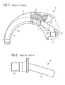
- Fig. 1 shows a side view of an upper portion of a housing 2 of a BTE hearing aid 1 according to the prior art.
- the upper portion of the housing 2 is continuously in a carrying hook 40, which is composed of a titanium tube 42 and a plastic extrusion 41.
- the titanium tube 42 For fastening the carrying hook 40 or the titanium tube 42, the titanium tube 42 has a connecting lug 43, which is likewise produced by a plastic extrusion coating of the titanium tube 42.
- the titanium tube 42 is further attached to a rear end facing away from the support hook 40 by a holding element 44 in the housing 2 of the BTE hearing aid 1.
- a disadvantage of such an embodiment of a BTE hearing aid 1 according to the prior art is that the titanium tube 42 is not connected to a mounting portion, such as. As a thread can be provided, by means of which the BTE hearing aid 1 and the support hook 40 can be easily connected to each other. It is therefore not possible, a releasable connection of the support hook 40 in the transition region to create the housing 2 of the BTE hearing aid 1. For replacement of the carrying hook 40, the housing 2 of the BTE hearing aid 1 must be opened. Furthermore, in such an embodiment, the carrying hook 40 is completely traversed by the titanium tube 42, which prevents a transparent embodiment of the carrying hook 40.
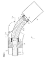
- Fig. 2 shows a solution according to the prior art, wherein a releasable attachment of a carrying hook is realized at an upper portion of a housing of a BTE hearing aid (all in the Fig. 2 not shown).
- the attachment of the carrying hook takes place at a consisting of a metal or a metal alloy connector 30 which can be installed in the upper part of the housing of the BTE hearing aid.
- the metal connector 30 is provided at its front, protruding from the BTE hearing aid section with an external thread 32 to which the carrying hook can be screwed.
- the carrying hook 40 is not as in the Fig. 1 constructed and has a male thread 32 of the connector 30 corresponding internal thread.
- the metal connection piece 30 has a sound conductor 34, which is formed materially in one piece with the section of the connection piece protruding from the BTE hearing device.
- the sound pipe 34 is provided at a certain angle relative to the remaining metal connector 30. This angle is adapted to a curvature of a respective area of the BTE hearing device.
- a free end of the sound conduit 34 is acoustically connected to a listener of the BTE hearing aid.
- a particular disadvantage here is that, depending on the BTE hearing aid different curvatures in the area of the BTE hearing aid for the metal connector 30 exist, so that the metal connector 30 must be individually adapted to the BTE hearing aid in question series.
- Fig. 3 shows an inventive arrangement of a receiver 10 and a connector 30, which are acoustically coupled to each other via a sound tube 20 according to the invention.
- the earpiece 10 is arranged within a housing 2 of a BTE hearing aid 1 according to the invention, and the connection piece 30 forms, with a section provided outside the housing 2, a mechanical connection for a wearing hook 40 which rests on a thread 32 of the section or the connecting piece 30 is screwable.
- the sound tube 20 can be connected according to the invention with the handset 10 and / or the connector 30.
- sound signals S which are generated by the handset 10, from the handset 10 to the connector 30 and from there into the carrying hook 40 transportable.
- the sound tube 20 is designed such that it can bridge different arrangements of the receiver 10 and the connection piece 30. Ie. - Apart from a length of the sound tube 20 - this should be such that it can acoustically couple differently positioned connector / receiver configurations 30/10.
- variable angle ⁇ which illustrates the angle ⁇ between the longitudinal ends 21, 23 and the longitudinal end portions 21, 23 of the sound tube 20. This corresponds in an installed position of the sound tube 20 and the angle ⁇ between a longitudinal center line L 10 of the earphone 10 and a longitudinal center line L 30 of the connector 30th
- the sound tube 20 is flexurally flexible, at least in a longitudinal center section 22. This In particular, a direction perpendicular to its longitudinal direction L.
- An acoustic connection between the receiver 10 and connector 30 is preferably carried out as follows: First, a longitudinal end portion 21, 23 of the sound tube 20 at the connector 30 or the handset 10 is mounted. This can be z. B. directly after the preparation of the connector 30 or directly after an installation of the handset 10. However, it is also possible to make this only when assembling the BTE hearing aid 1. Thereafter, the sound tube 20 is mounted on the handset 10 and the connector 30 by the sound tube 20 is accordingly bent onto the handset 10 or the connector 30 and then attached thereto.
- the receiver 10 and the connection piece 30 within the BTE hearing aid 1 and subsequently to fasten the sound tube 20 on / in the relevant part (receiver 10, connection piece 30).
- a partial assembly that is to say initially an installation of the earphone 10 or the connecting piece 30 in the BTE hearing aid 1, and a subsequent mounting of the sound tube 20 with the fitting 30 or the earpiece 10 provided thereon or the earpiece 10 is, of course, possible.
- the entire sound tube 20 or its longitudinal center section 22 is continuously bendable, as a result of which the mounted sound tube 20 or its longitudinal center section 22 is guided without kinking within the BTE hearing device 1.
- the entire sound tube 20 or its longitudinal center section 22 within the BTE hearing aid 1 is continuously bent and has - preferably apart from one or both mounting portions 26 of the sound tube 20 on the handset 10 or the connector 30 - a curved course.
- the sound tube preferably has 20 in the BTE hearing aid 1 mounted state no linear course.
- the sound tube 20 or its longitudinal center section 22 is elastically and / or plastically deformable in the region between the mounting sections 26. This relates in particular to the direction perpendicular to the longitudinal direction L of the sound tube 20.
- the sound tube 20 is preferably configured such that it essentially retains at least one inner, acoustic cross-section during bending.
- the sound tube 20 or its longitudinal center section 22 is plastically deformable.
- the sound tube 20 or its longitudinal center section 22 is designed in such a way that, during plastic bending, at least the inner cross section of the sound tube 20 is essentially retained and as little elastic recovery as possible occurs.
- a stiffening element 25 extends at least in sections in the longitudinal direction L on / within the wall 24.
- the stiffening element 25 is formed as a braid 25 within the sound tube 20, in particular as a wire mesh 25.
- the braid 25 is elastically and / or plastically deformable when the sound tube 20 is bent.
- the braid 25 is plastically deformable even at low deflections or low degrees of deformation of the sound tube 20, so that the sound tube 20 is replaced by the braid 25 its plastic deformability.
- the braid 25 is preferred suitable for substantially maintaining its inner cross-section when bending the sound tube 20.
- the sound tube 20 can be firmly connected by means of a plug and / or adhesive connection with the connector 30 and / or the handset 10. In this case, it is possible to attach the sound tube 20 to a relevant connection section 16, 36 of the receiver 10 or of the connection piece 30 and, if necessary, to glue it to this connection. However, it is also possible to omit such a connection piece 16, 36 and to insert the sound tube 20 with its relevant mounting portion 26 in the handset 10 and in the connector 30 and to attach there accordingly.
- the handset 10 and / or the connector 30 at least one projection 17, 37 which holds the sound tube 20 additionally or fixed. Preference is given to the respective projection 17, 37 completely encircling.
- the sound tube 20 can be fixedly connected to the receiver 10 or the connecting piece 30 without having to use adhesive. Another advantage is that, in contrast to an attachment by means of adhesive greater manufacturing tolerances in the production of the sound tube 20 and the corresponding terminal portion 16, 36 are possible. Furthermore, it is advantageous that the sound tube 20 can be easily detached from the handset 10 or the connecting piece 30 for cleaning.
- Fig. 4 shows an embodiment with at least one, preferably outer circumferential projection 17, 37 at the respective terminal portion 16, 36.
- this projection 17, 37 of the sound tube 20 is pushed away during its mounting on the handset 10 and the connector 30.
- a plurality of such projections 17, 37 may be provided.
- Fig. 5 shows further embodiments of a fastening according to the invention of the sound tube 20 on the handset 10 and the connecting piece 30.
- a projection 17, 37 of the corresponding connection portion 16, 36 engages in a recess 27 of the sound tube 20 a.
- This recess 27 is formed corresponding to the respective projection 17, 37.
- the recess 27 is formed as a triangular in cross-section, preferably inside the sound tube 20 completely circumferential groove.
- the projection 17, 37 is formed as a projection 17, 37 running around the outside of the relevant connection section 16, 36, which is also triangular in a cross section.
- this can also be designed vice versa, which should also apply to the other embodiments of the invention.
- Fig. 5 an inside formed on the sound tube 20 projection 28, which is preferably also provided completely encircling.
- the projection 28 is rounded. This projection 28 engages in a preferably completely circumferential recess 18, 38 of the receiver 10 and the connecting piece 30, which is formed in the illustrated embodiment as a groove which is triangular in cross-section.
- the embodiments of the 4 and 5 are freely combinable with each other or can be used multiple times.
- it is not absolutely necessary - like on the right in Fig. 5 shown - corresponding profiles of the projection 17, 37; 28 and the recess 27; 18, 38 provide. It is only necessary to ensure that a certain clamping action ( Fig. 4 ) or a positive and / or non-positive connection between the sound tube 20 and the corresponding terminal portion 16, 36 is produced.
Abstract
Description
Die Erfindung betrifft ein Hörhilfsgerät, insbesondere ein Hinter-dem-Ohr-Hörgerät mit einem Hörer und einem Anschlussstück. Ferner betrifft die Erfindung ein Verfahren zum Montieren eines Hörhilfsgeräts, insbesondere eines Hinter-dem-Ohr-Hörgeräts.The invention relates to a hearing aid, in particular a behind-the-ear hearing aid with a receiver and a connector. Furthermore, the invention relates to a method for mounting a hearing aid, in particular a behind-the-ear hearing aid.
Ein Anpassen von Hörgeräten an unterschiedliche Gehörschäden durch verschiedene Leistungsstärken und an differierende Kundenwünsche, sowie die Forderung der Kunden nach kleinen und kleinsten Baugrößen, zwingt die Hörgerätehersteller zu einer breiten Palette von Hörgeräten mit einem unterschiedlichen Funktionsumfang für unterschiedliche Leistungsstufen. Dies führt zu einer Vielzahl von unterschiedlich großen Hörgeräten, die individuell an Gehörschäden und Kundenwünsche anpassbar sind.Adapting hearing aids to different degrees of hearing loss due to different performance levels and different customer requirements, as well as customers' demand for small and very small sizes, forces hearing aid manufacturers to produce a wide range of hearing aids with different functionality for different performance levels. This leads to a variety of hearing aids of different sizes, which are individually adaptable to hearing damage and customer requirements.
Hörgeräte weisen im Allgemeinen ein Gehäuse auf, in welchem ein Mikrophon, eine Verstärkereinrichtung, ein Hörer und eine Energieversorgung, meist eine Zink-Luft-Batterie, angeordnet sind. Der Hörer ist mit einem akustischen Ausgang des Gehäuses verbunden, um die vom Hörgerät aufbereiteten und erzeugten akustischen Signale auszugeben.Hearing devices generally have a housing in which a microphone, an amplifier device, a receiver and a power supply, usually a zinc-air battery, are arranged. The handset is connected to an acoustic output of the housing to output the acoustic signals processed and generated by the hearing aid.
Hinter dem Ohr tragbare Hörgeräte (im Folgenden kurz als HdO-Hörgeräte bezeichnet) werden üblicherweise mittels eines Tragehakens hinter dem Ohr eines Hörgeräteträgers gehalten. Neben der Halterung des HdO-Hörgeräts erfüllt der Tragehaken in der Regel noch eine weitere Funktion. Der Tragehaken ist von einer Schallleitung durchzogen, durch welchen der vom Hörer des HdO-Hörgeräts erzeugte Schall zu einem mit dem vorderen Ende des Tragehakens verbundenen Schallschlauch transportiert und durch diesen mittels einer Otoplastik in einen Gehörgang des Hörgeräteträgers weitergeleitet wird.Behind the ear portable hearing aids (hereinafter referred to as BTE hearing aids) are usually held by a carrying hook behind the ear of a hearing aid wearer. In addition to the holder of the BTE hearing aid, the carrying hook usually fulfills another function. The carrying hook is traversed by a sound conductor, through which the sound generated by the earpiece of the BTE hearing device is transported to a sound tube connected to the front end of the carrying hook and forwarded by the earpiece into an auditory canal of the hearing device wearer.
In einer Ausführungsform eines solchen HdO-Hörgeräts besteht der Tragehaken aus einem gebogenen Titan-Röhrchen, das teilweise von einem Kunststoffmaterial umspritzt ist. Dieses Titan-Röhrchen ist von einer Befestigungsstelle am Hörer innerhalb des HdO-Hörgeräts bis zum vorderen Ende des Tragehakens durchgängig geführt. Für eine Befestigung des Titan-röhrchens im Gehäuse des HdOs, weist dieses in einem Bereich zwischen dem eigentlichen Gehäuse des HdO-Hörgeräts und dem Tragehaken eine Haltelasche aus Kunststoff auf, mittels welcher das Titanröhrchen am/im HdO-Hörgerät festgelegt wird.In one embodiment of such a BTE hearing aid, the carrying hook consists of a bent titanium tube which is partially encapsulated by a plastic material. This Titanium Tube is routed through the earhook inside the BTE Hearing Aid to the front of the Carrying Hook. For a fastening of the titanium tube in the housing of the BTE, this has in a region between the actual housing of the BTE hearing aid and the carrying hook a plastic retaining tab, by means of which the titanium tube is fixed on / in the BTE hearing aid.
Ein solches Hörgerät kann im Übergangsbereich zwischen dem Gehäuse des HdO-Hörgeräts und dem Tragehaken eine schlanke Bauform aufweisen, es muss jedoch für einen Austausch des Tragehakens stets das Gehäuse des Hörgeräts geöffnet werden. Ferner ist eine Schraubverbindung des Tragehakens mit dem Gehäuse des HdO-Hörgeräts nicht realisierbar.Such a hearing aid may have a slim design in the transition region between the housing of the BTE hearing aid and the carrying hook, but it is always necessary to open the housing of the hearing aid for replacement of the carrying hook. Furthermore, a screw connection of the carrying hook to the housing of the BTE hearing aid is not feasible.
Darüber hinaus sind HdO-Hörgeräte mit einem Metall-Anschlussstück für einen Tragehaken bekannt, welche an einem vorderen, am Gehäuse des HdO-Hörgeräts hervortretenden Abschnitt ein Gewinde aufweisen. Auf das Gewinde kann der Tragehaken aufgeschraubt werden, was im Reparaturfall einen einfachen Austausch des Tragehakens ermöglicht. Das Anschlussstück weist eine integrale Schallleitung auf, der in den Hörer des Hörgeräts mündet.In addition, BTE hearing aids are known with a metal fitting for a carrying hook, which have a thread on a front, on the housing of the BTE hearing aid protruding portion. On the thread of the carrying hook can be screwed, which allows a simple replacement of the carrying hook in case of repair. The connector has an integral sound conduit, which opens into the receiver of the hearing aid.
Durch das Anpassen der HdO-Hörgeräte an unterschiedliche Gehörschäden, z. B. aufgrund unterschiedlicher Leistungsstufen, sowie aus kosmetischen Gründen und auch zur Erhöhung des Tragekomforts, werden bei den HdO-Hörgeräten möglichst kleine und schmale Gehäusebauformen bevorzugt. Dies führt dazu, dass sich die Krümmungen in einem Bereich unterschiedlicher HdO-Hörgeräte ändern, an welchem der Tragehaken vorsehbar ist. Daher sind für unterschiedliche HdO-Hörgeräte verschiedene Metall-Anschlusstücke notwendig, da zwischen einem Anschlussbereich für den Tragehaken und der Schallleitung des Metall-Anschlussstücks ein festgelegter Winkel existiert, der von der jeweiligen Krümmung innerhalb eines speziellen HdO-Hörgeräts abhängt.By adapting the BTE hearing aids to different hearing damage, z. B. due to different levels of performance, as well as for cosmetic reasons and also to increase the wearing comfort, as small as possible and small housing designs are preferred in BTE hearing aids. As a result, the curvatures in a range of different BTE hearing aids change, on which the carrying hook can be provided. Therefore, different metal fittings are required for different BTE hearing aids, because there is a fixed angle between a terminal area for the carrying hook and the sound conduit of the metal terminal, which depends on the particular curvature within a specific BTE hearing aid.
Die
Es ist eine Aufgabe der Erfindung, ein verbessertes Hörhilfsgerät, insbesondere ein verbessertes HdO-Hörgerät, sowie ein verbessertes Montageverfahren für ein Hörhilfsgerät bzw. ein HdO-Hörgerät zur Verfügung zu stellen. Insbesondere ist es eine Aufgabe der Erfindung, ein Hörhilfsgerät und ein Montageverfahren für ein Hörhilfsgerät zur Verfügung zu stellen, wobei es ermöglicht ist, bei einem Hörhilfsgerät mit verschiedenen Gehäusebauformen, mit nur einem einzigen, standardisierten Anschlussstück eine Schallweiterleitung innerhalb des Hörhilfsgeräts zu realisieren.It is an object of the invention to provide an improved hearing aid, in particular an improved BTE hearing aid, as well as an improved mounting method for a hearing aid or a BTE hearing aid. In particular, it is an object of the invention to provide a hearing aid and a mounting method for a hearing aid, wherein it is possible to realize a hearing aid with different housing designs, with only a single, standardized connector a sound transmission within the hearing aid.
Erfindungsgemäß sollen insbesondere unterschiedliche Gehäusekrümmungen berücksichtigbar sein; d. h. mittels eines standardisierten Anschlussstücks sollen unterschiedliche Krümmungen des Gehäuses des Hörhilfsgeräts überbrückbar sein. Erfindungsgemäß soll, bevorzugt bei einem HdO-Hörgerät mit einem lösbar befestigbaren Tragehaken, in einem Übergangsbereich zwischen einem Tragehaken und dem eigentlichen Gehäuse des HdO-Hörgeräts, eine schmale Bauform realisiert sein.According to the invention, in particular different housing curvatures should be taken into account; d. H. By means of a standardized connector different curvatures of the housing of the hearing aid are to be bridged. According to the invention, preferably in a BTE hearing aid with a releasably attachable carrying hook, in a transition region between a carrying hook and the actual housing of the BTE hearing aid, a narrow design be realized.
Die Aufgabe der Erfindung wird mittels eines Hörhilfsgeräts, insbesondere mittels eines HdO-Hörgeräts, gemäß Anspruch 1 und durch ein Verfahren zum (Vor-)Montieren eines Hörhilfsgeräts, insbesondere eines HdO-Hörgeräts, gemäß Anspruch 15 gelöst.The object of the invention is achieved by means of a hearing aid, in particular by means of a BTE hearing aid, according to
Erfindungsgemäß wird das im Stand der Technik stofflich einstückig ausgebildete Metall-Anschlussstück in ein zweigeteiltes Anschlussstück aufgeteilt. Hierbei entsteht ein standardisiertes, für alle oder für eine Vielzahl von Hörhilfsgeräten einer einzigen oder einer Mehrzahl von Baureihen identisches, Anschlussstück, und ein Überbrückungs-Anschlussstück, das ein Schallsignal vom daran angeschlossenen Hörer zum eigentlichen standardisierten Anschlussstück transportieren kann. Hierbei ist das Überbrückungs-Anschlussstück bevorzugt als ein, wenigstens in einem Längsmittenabschnitt flexibler, Schallschlauch ausgebildet; d. h. der Längsmittenabschnitt des Schallschlauchs ist in einer Richtung senkrecht zu seiner Längsrichtung flexibel ausgebildet.According to the invention in the prior art materially integrally formed metal connector is divided into a two-piece connector. This results in a standardized, for all or for a variety of hearing aids of a single or a plurality of series identical, connector, and a bridging connector that can transport a sound signal from the connected receiver to the actual standardized connector. Here, the bridging connector is preferably designed as a, at least in a longitudinal center section flexible, sound tube; d. H. the longitudinal center section of the sound tube is flexible in a direction perpendicular to its longitudinal direction.
Erfindungsgemäß wird das vom Hörer des Hörhilfsgeräts erzeugte Schallsignal über den wenigstens im Längsmittenabschnitt biegeflexiblen Schallschlauch zum standardisierten Anschlussstück transportiert, wobei das Anschlussstück mit einem Gehäuse des Hörhilfsgeräts fest verbunden ist. An diesem Anschlussstück kann ein Tragehaken lösbar befestigt werden.According to the invention, the sound signal generated by the hearing aid of the hearing aid is transported via the sound tube, which is bendable at least in the longitudinal center section, to the standardized connecting piece, wherein the connecting piece is fixedly connected to a housing of the hearing aid. At this connector, a carrying hook can be releasably attached.
Ein erfindungsgemäßes Verfahren zum (Vor-)Montieren eines Hörhilfsgeräts erfolgt dergestalt, dass zuerst ein Längsendabschnitt des Schallschlauchs am Anschlussstück oder dem Hörer des Hörhilfsgeräts montiert wird. Anschließend wird der diesem Längsendabschnitt gegenüberliegende Längsendabschnitt des Schallschlauchs am Hörer bzw. am Anschlussstück befestigt, wobei Hörer und/oder Anschlussstück schon im Gehäuse des Hörhilfsgeräts montiert sein können. Je nach dem, ob keine, eine oder beide Komponenten (Hörer, Anschlussstück) schon im Hörhilfsgerät verbaut sind, wird der Schallschlauch beim erfindungsgemäßen Montageverfahren entsprechend ge- oder verbogen.An inventive method for (pre) mounting a hearing aid is carried out such that first a longitudinal end portion of the sound tube is mounted on the connector or the handset of the hearing aid. Subsequently, the this longitudinal end portion opposite longitudinal end portion of the sound tube is attached to the handset or on the connector, wherein the handset and / or connector can already be mounted in the housing of the hearing aid. Depending on whether no, one or both components (receiver, connector) are already installed in the hearing aid, the sound tube in accordance with the invention mounting method is bent or bent accordingly.
Durch das Vorsehen des erfindungsgemäßen zweigeteilten Anschlussstücks, bzw. das Vorsehen des erfindungsgemäßen Anschlussstücks und des erfindungsgemäßen in einer Richtung senkrecht zu seiner Längsrichtung biegeflexiblen Schallschlauchs, ist ein unterschiedlicher Winkel zwischen einer Einbaulage des Anschlussstücks und einer Einbaulage des Hörers innerhalb des Hörhilfsgeräts möglich. Somit sind identische Anschlussstücke und im Wesentlichen auch identische Schallschläuche für verschiedene Hörhilfsgeräte einsetzbar. Gegebenenfalls ist eine Länge des Schallschlauchs anzupassen.By providing the two-part connector according to the invention, or the provision of the connector according to the invention and in a direction perpendicular to its longitudinal direction bend flexible sound tube, a different angle between an installation position of the connector and an installation position of the listener within the hearing aid is possible. Thus, identical connecting pieces and substantially identical sound tubes for different hearing aids can be used. If necessary, adjust a length of the sound tube.
Erfindungsgemäß entfällt ein teurer und aufwändiger Produktionsprozess, um Metall-Anschlussstücke mit integraler, gewinkelter Schallleitung zu fertigen, und hiervon eine Vielzahl von Metall-Anschlussstücken mit unterschiedlichen Winkeln zwischen einem Anschlussabschnitt für den Tragehaken und der Schallleitung vorrätig zu halten. Erfindungsgemäß wird nur noch ein Design des Anschlussstücks produziert, und der unterschiedliche Winkel bei unterschiedlichen Hörhilfsgeräten wird vom Schallschlauch ausgeglichen bzw. überbrückt.According to the invention eliminates a costly and complex production process to produce metal fittings with integral, angled sound conduction, and to keep thereof a variety of metal fittings with different angles between a connection portion for the support hook and the sound conductor in stock. According to the invention, only one design of the connection piece is produced, and the different angle with different hearing aid devices is compensated or bridged by the sound tube.
In bevorzugten Ausführungsformen der Erfindung ist der Schallschlauch über seine gesamte Erstreckung in eine Längsrichtung, insbesondere in eine Richtung senkrecht zu seiner Längsrichtung, flexibel bzw. biegeflexibel ausgebildet. Hierdurch ist der Schallschlauch entlang seiner gesamten Längserstreckung in einer Richtung senkrecht dazu stetig biegbar. D. h. innerhalb des Hörhilfsgeräts ist der Schallschlauch dann knickfrei aufgenommen, wodurch sich das Schallsignal vom Hörer zum Anschlussstück gut, möglichst verlustfrei und reflektionsarm transportieren lässt.In preferred embodiments of the invention, the sound tube over its entire extension in a longitudinal direction, in particular in a direction perpendicular to its longitudinal direction, formed flexible or flexible. As a result, the sound tube is continuously bendable along its entire longitudinal extension in a direction perpendicular thereto. Ie. within the hearing aid, the sound tube is then recorded kink-free, which can be the sound signal from the handset to the connector well, lossless and possible low-reflection transport.
In bevorzugten Ausführungsformen der Erfindung ist der Schallschlauch derart elastisch verformbar, dass mittels dieser elastischen Verformbarkeit der Winkel zwischen der Einbaulage des Anschlussstücks und der Einbaulage des Hörers überbrückbar ist. Ferner kann dies auch durch eine plastische Verformbarkeit des Schlauchs erfolgen. Hierbei ist es insbesondere bevorzugt, dass diese plastische Verformbarkeit wieder derart rückgängig machbar ist, dass der Schallschlauch wieder in seine ursprüngliche Lage bzw. seine ursprüngliche Konfiguration bringbar ist. D. h. der Schallschlauch ist bei solchen Ausführungsformen der Erfindung möglichst reversibel plastisch verformbar.In preferred embodiments of the invention, the sound tube is elastically deformable such that by means of this elastic deformability of the angle between the mounting position of the connector and the mounting position of the listener can be bridged. Furthermore, this can also be done by a plastic deformability of the hose. In this case, it is particularly preferred that this plastic deformability can be reversed again in such a way that the sound tube can be brought back into its original position or its original configuration. Ie. the sound tube is in such embodiments of the invention as possible reversibly plastically deformable.
In sämtlichen Ausführungsformen der Erfindung ist es bevorzugt, dass der Schallschlauch beim Überbrücken der Distanz zwischen dem Hörer und dem Anschlussstück, also in seiner gebogenen Lage, gegenüber einer nicht gebogenen Lage im Wesentlichen in allen Querschnitten im Wesentlichen denselben Querschnitt beibehält. Dies betrifft insbesondere innere, bevorzugt kreisrund, ausgestaltete Querschnitte des Schallschlauchs, durch welche das Schallsignal hindurch tritt.In all embodiments of the invention, it is preferred that the sound tube, when bridging the distance between the receiver and the connection piece, ie in its curved position, maintains essentially the same cross-section with respect to a non-bent position substantially in all cross-sections. This relates in particular to inner, preferably circular, configured cross sections of the sound tube through which the sound signal passes.
In Ausführungsformen der Erfindung weist der Schallschlauch ein Geflecht, bevorzugt ein Drahtgeflecht, auf, das dem Schallschlauch eine gewisse (Querschnitts-)Stabilität verleiht. Hierdurch ist auch insbesondere eine Biegbarkeit des Schallschlauchs beeinflussbar. Wird das Geflecht plastisch verformt, so wird bevorzugt auch der Schallschlauch plastisch verformt. Analoges gilt für ein elastisches Verformen des Geflechts.In embodiments of the invention, the sound tube has a mesh, preferably a wire mesh, which gives the sound tube a certain (cross-sectional) stability. As a result, in particular a flexibility of the sound tube can be influenced. If the braid is plastically deformed, then preferably the sound tube is plastically deformed. The same applies to an elastic deformation of the braid.
Wenigstens der vordere Abschnitt des erfindungsgemäßen Anschlussstücks, welcher bevorzugt eine Schraubverbindung für den Tragehaken besitzt, ist aus einem Metall bzw. einer Metalllegierung hergestellt. Bevorzugt ist das gesamte erfindungsgemäße Anschlussstück aus Metall bzw. einer Metalllegierung geformt. Hierdurch wird für den Tragehaken eine notwendige Stabilität am Hörhilfsgerät bereitgestellt.At least the front portion of the connecting piece according to the invention, which preferably has a screw connection for the carrying hook, is made of a metal or a metal alloy. Preferably, the entire connector according to the invention is formed from metal or a metal alloy. As a result, a necessary stability is provided on the hearing aid for the carrying hook.
Der erfindungsgemäße Schallschlauch zwischen dem erfindungsgemäßen Anschlussstück und dem Hörer des Hörhilfsgeräts ist bevorzugt aus einem Kunststoff hergestellt. Beim Herstellen des Hörhilfsgeräts bzw. beim (Vor-)Montieren des Hörhilfsgeräts ist es bevorzugt, dass der Schallschlauch in einem beliebigen Winkel gebogen werden kann und damit universell in einem jeden Hörhilfsgerät einsetzbar ist. Der flexible Kunststoff-Schallschlauch wird einfach auf/in das Anschlussstück gesteckt und dadurch fixiert, und dann je nach Winkel zum Hörer hingebogen und dort ebenfalls fixiert. Dies kann natürlich kinematisch umgekehrt sein; d. h. der Kunststoff-Schallschlauch kann zuerst auf/in den Hörer gesteckt und dadurch fixiert werden und dann erst mit dem Anschlussstück befestigt werden.The sound tube according to the invention between the connector according to the invention and the receiver of the hearing aid is preferably made of a plastic. When manufacturing of the hearing aid or during (pre) mounting the hearing aid, it is preferred that the sound tube can be bent at any angle and thus universally applicable in any hearing aid. The flexible plastic sound tube is simply placed on / in the connector and thereby fixed, and then bent depending on the angle to the listener and also fixed there. Of course, this can be reversed kinematically; ie the plastic sound tube can first be placed on / in the receiver and thereby fixed and then attached only with the connector.
Eine jeweilige Montage des Schallschlauchs am/im Anschlussstück oder am/im Hörer kann über eine Steck- und/oder eine Klebeverbindung erfolgen. Hierbei ist es möglich, den Schallschlauch auf einen Vorsprung des Anschlussstücks und/oder einen Vorsprung des Hörers zu stecken; umgekehrt ist es natürlich möglich, den Schallschlauch in eine Ausnehmung im Anschlussstück und/oder eine Ausnehmung im Hörer einzustecken. Eine Mischform der Befestigungen ist natürlich ebenfalls anwendbar.A respective installation of the sound tube on / in the connector or on / in the handset can be done via a plug and / or an adhesive connection. It is possible to put the sound tube on a projection of the connector and / or a projection of the listener; conversely, it is of course possible to insert the sound tube in a recess in the connector and / or a recess in the handset. A mixed form of fortifications is of course also applicable.
Das erfindungsgemäße Auftrennen eines einzigen Metall-Anschlussstücks - welches einerseits die Schraubverbindung für den Tragehaken und andererseits die akustische Verbindung zum Hörer herstellt - in einen am Hörer befestigbaren Kunststoff-Schallschlauch und ein Metall-Anschlussstück, an welchem das verbleibende freie Ende des Kunststoff-Schallschlauchs befestigt wird, ist insgesamt kostengünstiger herzustellen. Dies ist insbesondere auf die Verwendung des Kunststoff-Schallschlauchs zurückzuführen, da dieser im Vergleich zur Metallleitung einerseits günstiger in der Herstellung ist und andererseits eine einfachere Bearbeitung ermöglicht.The separation of a single metal connector according to the invention - which on the one hand produces the screw connection for the carrying hook and on the other hand the acoustic connection to the handset - in a plastic sound tube attachable to the handset and a metal connector to which the remaining free end of the plastic sound tube attached is, overall, is cheaper to produce. This is due in particular to the use of the plastic sound tube, as it is cheaper to manufacture compared to the metal line on the one hand and on the other hand allows easier editing.
Das im Stand der Technik stofflich einstückig ausgebildete Metall-Anschlussstück kann nur einen einzigen Winkel zwischen der Einbaulage des Metall-Anschlussstücks und der Einbaulage des Hörers überbrücken. Erfindungsgemäß ist durch die Verwendung des Kunststoff-Schallschlauchs dieser Winkel nicht auf einen einzigen eingeschränkt, sondern mit dem erfindungsgemäßen Kunststoff-Schallschlauch sind eine Mehrzahl von Winkeln entsprechend überbrückbar, d. h. gewünschte Winkel können gemäß der Erfindung ohne Probleme gelegt werden. Man braucht daher für fast alle Hörgeräte einer Art oder einer Serie nur noch ein genormtes Anschlussstück und den biegbaren Kunststoff-Schallschlauch, die beide in allen Hörgeräten zur Anwendung kommen können. Eine einzige Anpassung ist allenfalls noch bei einer Länge des Kunststoff-Schallschlauchs notwendig.The material connector integrally formed in the prior art metal connector can only a single angle between the mounting position of the metal connector and the mounting position of the listener. According to the invention, this angle is not limited to a single one by the use of the plastic sound tube, but with the plastic sound tube according to the invention a plurality of angles can be bridged accordingly, ie desired angles can be laid according to the invention without problems. It is therefore necessary for almost all hearing aids of a type or series only a standardized connector and the flexible plastic sound tube, both of which can be used in all hearing aids. A single adaptation is possibly still necessary at a length of the plastic sound tube.
Weitere Ausführungsformen der Erfindung ergeben sich aus den übrigen abhängigen Ansprüchen.Further embodiments of the invention will become apparent from the remaining dependent claims.
Die Erfindung wird im Folgenden anhand von Ausführungsbeispielen unter Bezugnahme auf die beigefügte Zeichnung näher erläutert. In der Zeichnung zeigen:
- Fig. 1
- in einer teilweise offenen Seitenansicht eine Anordnung eines Tragehakens an einem HdO-Hörgerät gemäß dem Stand der Technik;
- Fig. 2
- ein Metall-Anschlussstück gemäß dem Stand der Technik für ein Hörgerät;
- Fig. 3
- eine teilweise geschnittene Seitenansicht einer erfindungsgemäßen Anordnung für einen Transport eines Schallsignals von einem Hörer des Hörgeräts zu einem erfindungsgemäßen Anschlussstück des Hörgeräts;
- Fig. 4
- in einer geschnittenen Seitenansicht eine erfindungsgemäße mechanische Verbindung eines erfindungsgemäßen Schallschlauchs mit dem Hörer und/oder dem Anschlussstück der Anordnung aus
Fig. 3 ; und - Fig. 5
- eine alternative erfindungsgemäße mechanische Verbindung zu
Fig. 4 .
- Fig. 1
- in a partially open side view of an arrangement of a carrying hook on a BTE hearing aid according to the prior art;
- Fig. 2
- a metal connector according to the prior art for a hearing aid;
- Fig. 3
- a partially sectioned side view of an inventive arrangement for transporting a sound signal from a handset of the hearing aid to a connector according to the invention of the hearing aid;
- Fig. 4
- in a sectional side view of an inventive mechanical connection of a sound tube according to the invention with the handset and / or the connection piece of the arrangement
Fig. 3 ; and - Fig. 5
- an alternative inventive mechanical connection to
Fig. 4 ,
Die Erfindung wird im Folgenden anhand eines hinter dem Ohr getragenen Hörgeräts - im Folgenden mit HdO-Hörgerät bezeichnet - näher erläutert. Die Erfindung soll jedoch nicht nur auf solche HdO-Hörgeräte beschränkt sein, sondern ganz im Allgemeinen auf Hörhilfsgeräte anwendbar sein; also auch Geräte betreffen, die nicht nur einem Verbessern einer Hörschwäche dienen, sondern die auch geeignet sind, eine Hörfähigkeit eines Hörhilfsgeräteträgers in einer akustisch schwierigen Situation - wie z. B. auf einer Baustelle - zu verbessern. Dies betrifft z. B. einen Gehörschutz mit integriertem Funkgerät.The invention will be explained in more detail below with reference to a hearing aid worn behind the ear - hereinafter referred to as BTE hearing aid. However, the invention should not be limited only to such BTE hearing aids, but quite generally applicable to hearing aid devices; So also devices affect that not only serve to improve a hearing impairment, but are also suitable hearing a Hörhilfsgeräteträgers in an acoustically difficult situation - such. B. on a construction site - to improve. This concerns z. As a hearing protection with integrated radio.
Zur Befestigung des Tragehakens 40 bzw. des Titan-Röhrchens 42, weist das Titan-Röhrchen 42 eine Anschlusslasche 43 auf, die ebenfalls durch eine Kunststoffumspritzung des Titan-Röhrchens 42 hergestellt ist. Das Titan-Röhrchen 42 ist ferner an einem hinteren, dem Tragehaken 40 abgewandten Ende, durch ein Halteelement 44 im Gehäuse 2 des HdO-Hörgeräts 1 befestigt.For fastening the carrying
Nachteilig bei einer solchen Ausführungsform eines HdO-Hörgeräts 1 gemäß dem Stand der Technik ist, dass das Titan-Röhrchen 42 nicht mit einem Befestigungsabschnitt, wie z. B. einem Gewinde, versehen werden kann, mittels welchem das HdO-Hörgerät 1 und der Tragehaken 40 einfach miteinander verbunden werden können. Es ist daher nicht möglich, eine lösbare Verbindung des Tragehakens 40 im Übergangsbereich zum Gehäuse 2 des HdO-Hörgeräts 1 zu schaffen. Für einen Austausch des Tragehakens 40 muss das Gehäuse 2 des HdO-Hörgeräts 1 geöffnet werden. Des Weiteren ist bei einer solchen Ausführungsform der Tragehaken 40 vollständig vom Titan-Röhrchen 42 durchzogen, was eine transparente Ausführungsform des Tragehakens 40 verhindert.A disadvantage of such an embodiment of a
Das Metall-Anschlussstück 30 ist an seinem vorderen, aus dem HdO-Hörgerät herausstehenden Abschnitt mit einem Außengewinde 32 versehen, auf das der Tragehaken aufgeschraubt werden kann. Hierbei ist der Tragehaken 40 nicht wie bei der
Ferner weist das Metall-Anschlussstück 30 eine Schallleitung 34 auf, welche stofflich einstückig mit dem aus dem HdO-Hörgerät herausstehenden Abschnitt des Anschlussstücks ausgebildet ist. Hierbei ist die Schallleitung 34 mit einem gewissen Winkel gegenüber dem restlichen Metall-Anschlussstück 30 vorgesehen. Dieser Winkel ist an eine Krümmung eines betreffenden Bereichs des HdO-Hörgeräts angepasst. Ein freies Ende der Schallleitung 34 wird mit einem Hörer des HdO-Hörgeräts akustisch verbunden.Furthermore, the
Insbesondere nachteilig hierbei ist, dass je nach HdO-Hörgerät unterschiedliche Krümmungen im betreffenden Bereich des HdO-Hörgeräts für das Metall-Anschlussstück 30 existieren, sodass das Metall-Anschlussstück 30 individuell an das betreffende HdO-Hörgerät einer Serie angepasst werden muss.A particular disadvantage here is that, depending on the BTE hearing aid different curvatures in the area of the BTE hearing aid for the
Der Schallschlauch 20 ist gemäß der Erfindung mit dem Hörer 10 und/oder dem Anschlussstück 30 verbindbar. Hierbei ist es möglich, den Schallschlauch 20 als separates Teil - also getrennt vom Hörer 10 und Anschlussstück 30 - auszubilden oder den Schallschlauch 20 mit dem Hörer 10 bzw. dem Anschlussstück 30 vorzusehen bzw. auszubilden. Mittels des Schallschlauchs 20 sind Schallsignale S, welche vom Hörer 10 generiert werden, vom Hörer 10 zum Anschlussstück 30 und von dort in den Tragehaken 40 transportierbar.The
Erfindungsgemäß ist der Schallschlauch 20 derart ausgebildet, dass er unterschiedliche Anordnungen von Hörer 10 und Anschlussstück 30 überbrücken kann. D. h. - abgesehen von einer Länge des Schallschlauchs 20 - soll dieser derart beschaffen sein, dass er unterschiedlich zueinander positionierte Anschlussstück/Hörer-Konfigurationen 30/10 akustisch koppeln kann.According to the invention, the
Dies ist mit dem in
Erfindungsgemäß ist der Schallschlauch 20 wenigstens in einem Längsmittenabschnitt 22 biegeflexibel ausgebildet. Dies betrifft insbesondere eine Richtung senkrecht zu seiner Längsrichtung L. Ein Herstellen einer akustischen Verbindung zwischen Hörer 10 und Anschlussstück 30 erfolgt dabei bevorzugt folgendermaßen: Zunächst wird ein Längsendabschnitt 21, 23 des Schallschlauchs 20 am Anschlussstück 30 oder dem Hörer 10 montiert. Dies kann z. B. direkt nach der Herstellung des Anschlussstücks 30 oder direkt nach einer Montage des Hörers 10 erfolgen. Es ist jedoch auch möglich, dies erst beim Zusammenbauen des HdO-Hörgeräts 1 vorzunehmen. Danach wird der Schallschlauch 20 am Hörer 10 bzw. dem Anschlussstück 30 montiert, indem der Schallschlauch 20 entsprechend auf den Hörer 10 oder das Anschlussstück 30 hingebogen wird und anschließend daran befestigt wird.According to the invention, the
Erfindungsgemäß ist es möglich, zunächst den Hörer 10 und das Anschlussstück 30 innerhalb des HdO-Hörgeräts 1 zu montieren und daran anschließend den Schallschlauch 20 am/im betreffenden Teil (Hörer 10, Anschlussstück 30) zu befestigen. Es ist jedoch auch möglich, zunächst den Hörer 10 über den Schallschlauch 20 mit dem Anschlussstück 30 zu verbinden und anschließend diese gemeinsam im HdO-Hörgerät 1 zu montieren. Eine teilweise Montage, also zunächst eine Montage des Hörers 10 oder des Anschlussstücks 30 im HdO-Hörgerät 1, und eine anschließende Montage des Schallschlauchs 20 mit dem daran vorgesehenen oder dem daran vorzusehenden Anschlussstück 30 bzw. dem Hörer 10 ist natürlich möglich.According to the invention, it is first possible to mount the
In bevorzugten Ausführungsformen der Erfindung ist der gesamte Schallschlauch 20 bzw. dessen Längsmittenabschnitt 22 stetig biegbar, wodurch der montierte Schallschlauch 20 bzw. dessen Längsmittenabschnitt 22 innerhalb des HdO-Hörgeräts 1 knickfrei geführt ist. Bevorzugt ist dabei der gesamte Schallschlauch 20 bzw. dessen Längsmittenabschnitt 22 innerhalb des HdO-Hörgeräts 1 stetig gebogen und besitzt - bevorzugt abgesehen von einem oder beiden Montageabschnitten 26 des Schallschlauchs 20 am Hörer 10 oder dem Anschlussstück 30 - einen gekrümmten Verlauf. D. h. bevorzugt abgesehen von dem oder den Montageabschnitten 26 besitzt der Schallschlauch 20 im HdO-Hörgerät 1 montierten Zustand keinen linearen Verlauf.In preferred embodiments of the invention, the
Erfindungsgemäß ist der Schallschlauch 20 bzw. dessen Längsmittenabschnitt 22 im Bereich zwischen den Montageabschnitten 26 elastisch und/oder plastisch verformbar. Dies betrifft insbesondere die Richtung senkrecht zur Längsrichtung L des Schallschlauchs 20. Der Schallschlauchs 20 ist dabei bevorzugt derart konfiguriert, dass er beim Biegen wenigstens einen inneren, akustischen Querschnitt im Wesentlichen beibehält.According to the invention, the
In bevorzugten Ausführungsformen der Erfindung ist der Schallschlauch 20 bzw. dessen Längsmittenabschnitt 22 plastisch verformbar. Hierbei ist der Schallschlauch 20 bzw. dessen Längsmittenabschnitt 22 derart ausgebildet, dass beim plastischen Verbiegen wenigstens der innere Querschnitt des Schallschlauchs 20 im Wesentlichen beibehalten wird und eine möglichst geringe elastische Rückverformung auftritt.In preferred embodiments of the invention, the
In bevorzugten Ausführungsformen der Erfindung weist der Schallschlauch 20 bzw. dessen Längsmittenabschnitt 22 an bzw. in seiner Wandung 24 ein Versteifungselement 25 auf, das dem Schallschlauch 20 Stabilität und Biegbarkeit verleiht. Ein solches Versteifungselement 25 erstreckt sich dabei wenigstens abschnittsweise in Längsrichtung L an/innerhalb der Wandung 24.In preferred embodiments of the invention, the
In bevorzugten Ausführungsformen der Erfindung ist das Versteifungselement 25 als ein Geflecht 25 innerhalb des Schallschlauchs 20, insbesondere als ein Drahtgeflecht 25, ausgebildet. Erfindungsgemäß ist dabei das Geflecht 25 beim Verbiegen des Schallschlauchs 20 elastisch und/oder plastisch verformbar. Bevorzugt ist das Geflecht 25 auch schon bei geringen Verbiegungen bzw. geringen Verformungsgraden des Schallschlauchs 20 plastisch verformbar, sodass der Schallschlauch 20 durch das Geflecht 25 seine plastische Verformbarkeit erhält. Ferner ist das Geflecht 25 bevorzugt dazu geeignet, beim Verbiegen des Schallschlauchs 20 dessen inneren Querschnitt im Wesentlichen beizubehalten.In preferred embodiments of the invention, the stiffening
Der Schallschlauch 20 kann mittels einer Steck- und/oder Klebverbindung mit dem Anschlussstück 30 und/oder dem Hörer 10 fest verbunden werden. Hierbei ist es möglich, den Schallschlauch 20 auf einen betreffenden Anschlussabschnitt 16, 36 des Hörers 10 bzw. des Anschlussstücks 30 aufzustecken und - falls notwendig - mit diesem zu verkleben. Es ist jedoch auch möglich, ein solches Anschlussstück 16, 36 wegzulassen und den Schallschlauch 20 mit seinem betreffenden Montageabschnitt 26 in den Hörer 10 bzw. in das Anschlussstück 30 einzustecken und dort entsprechend zu befestigen.The
Die
Dies hat erfindungsgemäß den Vorteil, dass der Schallschlauch 20 mit dem Hörer 10 bzw. dem Anschlussstück 30 fest verbunden werden kann, ohne dass Klebstoff verwendet werden muss. Ein weiterer Vorteil ist, dass im Gegensatz zu einer Befestigung mittels Klebstoff größere Fertigungstoleranzen bei der Herstellung des Schallschlauchs 20 und des entsprechenden Anschlussabschnitts 16, 36 möglich sind. Ferner ist von Vorteil, dass der Schallschlauch 20 zum Reinigen leicht vom Hörer 10 bzw. dem Anschlussstück 30 abgelöst werden kann.This has the advantage according to the invention that the
Im vorliegenden Ausführungsbeispiel ist die Ausnehmung 27 als eine im Querschnitt dreieckige, bevorzugt innen am Schallschlauch 20 vollständig umlaufende Nut ausgebildet. Korrespondierend dazu ist der Vorsprung 17, 37 als ein außen am betreffenden Anschlussabschnitt 16, 36 umlaufender Vorsprung 17, 37 ausgebildet, der in einem Querschnitt ebenfalls dreieckig ist. Dies kann natürlich auch umgekehrt ausgebildet sein, was ebenso für die anderen Ausführungsformen der Erfindung gelten soll.In the present embodiment, the recess 27 is formed as a triangular in cross-section, preferably inside the
Ferner zeigt
Die Ausführungsformen der
Des Weiteren ist es möglich, die Anordnung eines oder beider Montageabschnitte 26 des Schallschlauchs 20 mit dem entsprechenden Anschlussabschnitt 16, 26 zu vertauschen; also den betreffenden Montageabschnitt 26 innerhalb des betreffenden Anschlussabschnitts 16, 26 vorzusehen. Hierbei können dann die Ausführungsformen der Erfindung gemäß den
Claims (17)
der Schallschlauch (20) wenigstens in einem Längsmittenabschnitt (22), in einer Richtung senkrecht zu seiner Längsrichtung (L), biegeflexibel ausgebildet ist.Hearing aid, in particular BTE hearing aid (1), with a receiver (10) for generating a sound signal (S), a connection piece (30) for outputting the sound signal (S), and a sound tube (20) for transporting the sound signal (S) between the receiver (10) and the connector (30), wherein
the sound tube (20) is flexurally flexible at least in a longitudinal center section (22), in a direction perpendicular to its longitudinal direction (L).
in einem Winkel (α) zwischen ca. 180° und ca. 0°, insbesondere zwischen 180±30° und 90±20°, bevorzugt zwischen 180±20° und 135±10°, insbesondere bevorzugt zwischen 180±10° und 150±10° und insbesondere besonders bevorzugt zwischen 180±5° und 165±5° anordenbar und/oder gebogen sind.Hearing aid according to one of claims 1 to 11, wherein the two longitudinal ends or the two longitudinal end portions (21, 23) of the sound tube (20) over the bending-flexible longitudinal center section (22),
at an angle (α) between about 180 ° and about 0 °, in particular between 180 ± 30 ° and 90 ± 20 °, preferably between 180 ± 20 ° and 135 ± 10 °, particularly preferably between 180 ± 10 ° and 150 ± 10 ° and in particular more preferably between 180 ± 5 ° and 165 ± 5 ° can be arranged and / or bent.
Applications Claiming Priority (1)
| Application Number | Priority Date | Filing Date | Title |
|---|---|---|---|
| DE102007052648A DE102007052648A1 (en) | 2007-11-05 | 2007-11-05 | Hearing aid, in particular BTE hearing aid |
Publications (2)
| Publication Number | Publication Date |
|---|---|
| EP2056625A2 true EP2056625A2 (en) | 2009-05-06 |
| EP2056625A3 EP2056625A3 (en) | 2013-01-09 |
Family
ID=40336175
Family Applications (1)
| Application Number | Title | Priority Date | Filing Date |
|---|---|---|---|
| EP08105041A Withdrawn EP2056625A3 (en) | 2007-11-05 | 2008-08-14 | Hearing aid, in particular BtE hearing aid |
Country Status (3)
| Country | Link |
|---|---|
| US (1) | US20090116673A1 (en) |
| EP (1) | EP2056625A3 (en) |
| DE (1) | DE102007052648A1 (en) |
Families Citing this family (4)
| Publication number | Priority date | Publication date | Assignee | Title |
|---|---|---|---|---|
| DE102010007609A1 (en) * | 2010-02-11 | 2011-08-11 | Siemens Medical Instruments Pte. Ltd. | Handset hose with strain relief and hearing aid |
| DE102010041524A1 (en) * | 2010-09-28 | 2012-02-02 | Siemens Medical Instruments Pte. Ltd. | Hearing aid apparatus for use as in-the-ear apparatus, has receiver unit comprising receiver tube for relaying acoustic output signals of receiver, where receiver tube is made of elastic material and placed via portion of receiver unit |
| DE102019202651A1 (en) | 2019-02-27 | 2020-01-23 | Sivantos Pte. Ltd. | Sound tube and BTE hearing aid |
| CN109862499A (en) * | 2019-04-03 | 2019-06-07 | 惠州市锦好医疗科技股份有限公司 | High-performance acoustic-electric modulus of conversion group, high-power hearing aid module and ear-level hearing aid |
Citations (1)
| Publication number | Priority date | Publication date | Assignee | Title |
|---|---|---|---|---|
| DE102006004033A1 (en) | 2006-01-27 | 2007-08-09 | Siemens Audiologische Technik Gmbh | Otoplastic for connecting hearing aid or another hearing device to auditory canal with help of sound hose comprises fastening device, which has tube socket, where outside diameter of tube socket is larger than inside diameter of socket |
Family Cites Families (20)
| Publication number | Priority date | Publication date | Assignee | Title |
|---|---|---|---|---|
| US2754365A (en) * | 1952-09-15 | 1956-07-10 | Maico Company Inc | Acoustical tone control for wearable hearing aids |
| US2939923A (en) * | 1955-08-03 | 1960-06-07 | John D Henderson | Hearing aid plastic ear pieces |
| USRE26174E (en) * | 1961-12-05 | 1967-03-21 | Leale hearing aid | |
| US3368644A (en) * | 1966-03-28 | 1968-02-13 | John D. Henderson | Hearing aid tone tuning device and method |
| CH648172A5 (en) * | 1979-06-12 | 1985-02-28 | Minisonic Ag | Hearing-aid to be worn in the ear |
| DE8316771U1 (en) * | 1983-06-08 | 1983-09-29 | Siemens AG, 1000 Berlin und 8000 München | SMALL HEATER |
| US5046580A (en) * | 1990-08-17 | 1991-09-10 | Barton James I | Ear plug assembly for hearing aid |
| US5195139A (en) * | 1991-05-15 | 1993-03-16 | Ensoniq Corporation | Hearing aid |
| US6681022B1 (en) * | 1998-07-22 | 2004-01-20 | Gn Resound North Amerca Corporation | Two-way communication earpiece |
| DE29819415U1 (en) * | 1998-10-30 | 1999-01-28 | Siemens Audiologische Technik | Carrying hook for hearing aids that can be worn behind the ear |
| US6940988B1 (en) * | 1998-11-25 | 2005-09-06 | Insound Medical, Inc. | Semi-permanent canal hearing device |
| US6879696B1 (en) * | 2000-06-06 | 2005-04-12 | Phonak Ag | In-ear hearing aid and method for its manufacture |
| US7110562B1 (en) * | 2001-08-10 | 2006-09-19 | Hear-Wear Technologies, Llc | BTE/CIC auditory device and modular connector system therefor |
| US7522743B2 (en) * | 2002-01-07 | 2009-04-21 | Step Communications | High comfort sound delivery system |
| US7532733B2 (en) * | 2003-06-30 | 2009-05-12 | Siemens Hearing Instruments, Inc. | Feedback reducing receiver mount and assembly |
| DE102005036849A1 (en) * | 2005-08-04 | 2007-02-22 | Siemens Audiologische Technik Gmbh | Receiver tube with damping element and corresponding hearing device |
| DE102006029819A1 (en) * | 2006-06-28 | 2008-01-03 | Siemens Audiologische Technik Gmbh | Hearing aid with a fastening for a receiver tube |
| DE102007014131A1 (en) * | 2007-03-23 | 2008-09-25 | Siemens Audiologische Technik Gmbh | Hearing aid with a fastening of a receiver tube |
| DE102007044550A1 (en) * | 2007-09-18 | 2009-03-26 | Siemens Medical Instruments Pte. Ltd. | Sound channel for a hearing device and corresponding manufacturing method |
| US8116495B2 (en) * | 2008-03-31 | 2012-02-14 | Starkey Laboratories, Inc. | Reinforced earbud device, system and method |
-
2007
- 2007-11-05 DE DE102007052648A patent/DE102007052648A1/en not_active Ceased
-
2008
- 2008-08-14 EP EP08105041A patent/EP2056625A3/en not_active Withdrawn
- 2008-11-05 US US12/264,988 patent/US20090116673A1/en not_active Abandoned
Patent Citations (1)
| Publication number | Priority date | Publication date | Assignee | Title |
|---|---|---|---|---|
| DE102006004033A1 (en) | 2006-01-27 | 2007-08-09 | Siemens Audiologische Technik Gmbh | Otoplastic for connecting hearing aid or another hearing device to auditory canal with help of sound hose comprises fastening device, which has tube socket, where outside diameter of tube socket is larger than inside diameter of socket |
Also Published As
| Publication number | Publication date |
|---|---|
| DE102007052648A1 (en) | 2009-05-07 |
| US20090116673A1 (en) | 2009-05-07 |
| EP2056625A3 (en) | 2013-01-09 |
Similar Documents
| Publication | Publication Date | Title |
|---|---|---|
| EP2116100B1 (en) | Earphone | |
| EP1874093A2 (en) | Hearing aid with a fastener for a hearing tube | |
| DE102007014131A1 (en) | Hearing aid with a fastening of a receiver tube | |
| EP1061772A2 (en) | Tubular body for sound transmission, in particular for hearing aids | |
| EP1517170B1 (en) | Hearing aid attachable to a spectacle temple | |
| EP2003930B1 (en) | Hearing aid with connecting piece attached to case frame | |
| CH699444B1 (en) | Hearing aid. | |
| EP2056625A2 (en) | Hearing aid, in particular BtE hearing aid | |
| EP2007172B1 (en) | Sound emitting pipes with 2 component design | |
| EP2360949A2 (en) | Hearing tube with torsion relief and hearing aid | |
| EP1847868B1 (en) | Behind the ear hearing device including a spectacles adapter with a thin acoustic tube | |
| DE10333293A1 (en) | Connector for hearing aid holder hook | |
| EP2043387A1 (en) | Acoustic tube for a hearing procedure | |
| DE102006046698B4 (en) | Sound conductor and hearing device | |
| EP0821541A2 (en) | Hearing aid which is to be worn completely in the ear canal and which is individualised by moulding a body | |
| EP1998593A1 (en) | Eartip for a hearing aid with retaining ring | |
| DE102005019994B4 (en) | hearing Aid | |
| EP3399775B1 (en) | Module for installing in a hearing aid | |
| EP1622421A2 (en) | Hearing aid and method of manufacturing the same | |
| DE102007053834B4 (en) | Hearing aid, in particular BTE hearing aid | |
| EP1841287B1 (en) | In-the-ear hearing aid with a band element for fixing the faceplate | |
| DE102009014114B4 (en) | Hearing aid module and hearing glasses | |
| EP1443802A2 (en) | Behind-the-ear hearing aid | |
| DE102006050502A1 (en) | Hearing device for attachment to external ear of user, has concha-clip detachably attached to connecting line and/or external earpiece in different angle positions in form-fit manner, where clip is designed as plastic injection-molded part | |
| DE102015226813A1 (en) | hearing Aid |
Legal Events
| Date | Code | Title | Description |
|---|---|---|---|
| PUAI | Public reference made under article 153(3) epc to a published international application that has entered the european phase |
Free format text: ORIGINAL CODE: 0009012 |
|
| AK | Designated contracting states |
Kind code of ref document: A2 Designated state(s): AT BE BG CH CY CZ DE DK EE ES FI FR GB GR HR HU IE IS IT LI LT LU LV MC MT NL NO PL PT RO SE SI SK TR |
|
| AX | Request for extension of the european patent |
Extension state: AL BA MK RS |
|
| PUAL | Search report despatched |
Free format text: ORIGINAL CODE: 0009013 |
|
| AK | Designated contracting states |
Kind code of ref document: A3 Designated state(s): AT BE BG CH CY CZ DE DK EE ES FI FR GB GR HR HU IE IS IT LI LT LU LV MC MT NL NO PL PT RO SE SI SK TR |
|
| AX | Request for extension of the european patent |
Extension state: AL BA MK RS |
|
| RIC1 | Information provided on ipc code assigned before grant |
Ipc: H04R 25/00 20060101AFI20121204BHEP |
|
| 17P | Request for examination filed |
Effective date: 20130705 |
|
| RBV | Designated contracting states (corrected) |
Designated state(s): AT BE BG CH CY CZ DE DK EE ES FI FR GB GR HR HU IE IS IT LI LT LU LV MC MT NL NO PL PT RO SE SI SK TR |
|
| AKX | Designation fees paid |
Designated state(s): AT BE BG CH CY CZ DE DK EE ES FI FR GB GR HR HU IE IS IT LI LT LU LV MC MT NL NO PL PT RO SE SI SK TR |
|
| 17Q | First examination report despatched |
Effective date: 20131016 |
|
| RAP1 | Party data changed (applicant data changed or rights of an application transferred) |
Owner name: SIVANTOS PTE. LTD. |
|
| STAA | Information on the status of an ep patent application or granted ep patent |
Free format text: STATUS: THE APPLICATION IS DEEMED TO BE WITHDRAWN |
|
| 18D | Application deemed to be withdrawn |
Effective date: 20160120 |