EP1517170B1 - Hearing aid attachable to a spectacle temple - Google Patents
Hearing aid attachable to a spectacle temple Download PDFInfo
- Publication number
- EP1517170B1 EP1517170B1 EP04019231A EP04019231A EP1517170B1 EP 1517170 B1 EP1517170 B1 EP 1517170B1 EP 04019231 A EP04019231 A EP 04019231A EP 04019231 A EP04019231 A EP 04019231A EP 1517170 B1 EP1517170 B1 EP 1517170B1
- Authority
- EP
- European Patent Office
- Prior art keywords
- hearing aid
- housing
- glasses
- channel
- bendable
- Prior art date
- Legal status (The legal status is an assumption and is not a legal conclusion. Google has not performed a legal analysis and makes no representation as to the accuracy of the status listed.)
- Not-in-force
Links
Images

Classifications
-
- G—PHYSICS
- G02—OPTICS
- G02C—SPECTACLES; SUNGLASSES OR GOGGLES INSOFAR AS THEY HAVE THE SAME FEATURES AS SPECTACLES; CONTACT LENSES
- G02C5/00—Constructions of non-optical parts
- G02C5/14—Side-members
- G02C5/143—Side-members having special ear pieces
-
- G—PHYSICS
- G02—OPTICS
- G02C—SPECTACLES; SUNGLASSES OR GOGGLES INSOFAR AS THEY HAVE THE SAME FEATURES AS SPECTACLES; CONTACT LENSES
- G02C11/00—Non-optical adjuncts; Attachment thereof
- G02C11/06—Hearing aids
Landscapes
- Physics & Mathematics (AREA)
- Health & Medical Sciences (AREA)
- General Physics & Mathematics (AREA)
- Ophthalmology & Optometry (AREA)
- Optics & Photonics (AREA)
- Acoustics & Sound (AREA)
- General Health & Medical Sciences (AREA)
- Otolaryngology (AREA)
- Eyeglasses (AREA)
- Details Of Audible-Bandwidth Transducers (AREA)
- Adornments (AREA)
Abstract
Description
Die Erfindung betrifft ein an einem Brillenbügel befestigbares Hörhilfegerät.The invention relates to an attachable to a temples hearing aid.
Aus der
Aus der
Aus der
Aus der
Aufgabe der vorliegenden Erfindung ist es, ein an einem Brillenbügel befestigbares Hörhilfegerät zu schaffen, bei dem die Brille auch nach dem Lösen des Hörhilfegerätes von dem Brillenbügel noch getragen werden kann.The object of the present invention is to provide a hearing aid device which can be fastened to a temple piece and in which the spectacles can still be carried by the temple piece even after the hearing aid has been released.
Diese Aufgabe wird bei einem an einem Brillenbügel einer von einem Träger tragbaren Brille befestigbaren Hörhilfegerät mit einen das Hörhilfegerät zumindest teilweise durchziehenden Kanal zur Aufnahme eines biegbaren Brillenbügel-Endstücks gelöst durch ein zumindest in einem Teilbereich biegbares Gehäuse, wobei das Gehäuse und der Kanal so ausgebildet sind, dass das Gehäuse zusammen mit dem in den Kanal eingeführten Brillenbügel-Endstück biegbar ist zur individuellen Anpassung der Form des Hörhilfegerätes an den Träger.This object is achieved in a hearing aid device which can be fastened to a spectacle frame of a pair of spectacles that can be worn by a wearer with a channel for receiving a bendable end piece of a hearing aid by a housing bendable at least in a partial area, the housing and the channel being formed in this way in that the housing, together with the temples end piece inserted into the channel, is bendable for individual adaptation of the shape of the hearing aid to the wearer.
Üblicherweise bestehen Brillenbügel aus einem Metall oder einer Metalllegierung. Zur Anpassung an den jeweiligen Brillenträger ist der im Ohrbereich befindliche Teil des Brillenbügels, das sogenannte Brillenbügel-Endstück, durch Biegen plastisch verformbar. Die Biegung zur Anpassung des Brillenbügels erfolgt in der Regel unter Wärmeeinwirkung.Usually, temples consist of a metal or a metal alloy. To adapt to the respective wearer of glasses located in the ear area part of the eyeglass temple, the so-called eyeglass temple end piece, by bending plastically deformable. The bend to adjust the eyeglass temple is usually under the action of heat.
Um den Tragekomfort zu erhöhen sowie aus kosmetischen Gründen ist auf das Brillenbügel-Endstück ein Kunststoff-Tragekörper aufgeschoben. Dieser ist elastisch und passt sich daher der Biegung des Brillenbügel-Endstücks an.To increase the wearing comfort and for cosmetic reasons, a plastic carrying body is pushed onto the temples tail. This is elastic and therefore adapts to the bending of the eyeglass end piece.
Mit einem Hörhilfegerät gemäß der Erfindung ist es möglich, aus nahezu jeder handelsüblichen Brille mit dem beschriebenen Aufbau eine Hörbrille herzustellen. Es muss hierfür lediglich der Kunststoff-Tragekörper von dem Brillenbügel-Endstück abgezogen und das Hörhilfegerät gemäß der Erfindung aufgeschoben werden. Innerhalb des Gehäuses des Hörhilfegerätes gemäß der Erfindung ist ein Hohlraum (Kanal) zur Aufnahme des Brillenbügel-Endstücks ausgebildet. In diesen Kanal kann das Brillenbügel-Endstück eingeführt werden, ohne hierzu den Brillenbügel kürzen und damit die Brille beschädigen zu müssen. Zur individuellen Anpassung an den Träger der so gebildeten Hörbrille wird dann das Brillenbügel-Endstück zusammen mit dem Hörhilfegerät in Form gebogen. Das somit in das Gehäuse des Hörhilfegerätes eingeführte Brillenbügel-Endstück dient somit neben der Befestigung des Hörhilfegerätes an der Brille auch zur Formgebung und Versteifung des Hörhilfegeräte-Gehäuses. Das Gehäuse des Hörhilfegerätes kann aus den gleichen Kunststoffen aufgebaut sein, die üblicherweise auch zur Herstellung der Kunststoff-Tragekörper verwendet werden. Sowohl kalt plastisch verformbare als auch unter Wärmeeinwirkung plastisch verformbare (thermoplastische) Kunststoffe sind möglich.With a hearing aid according to the invention, it is possible to produce from almost any standard glasses with the described construction a hearing glasses. It just has to the plastic carrying body is removed from the temples tail and the hearing aid be postponed according to the invention. Within the housing of the hearing aid according to the invention, a cavity (channel) is formed for receiving the eyeglass temple end piece. In this channel, the temples tail can be inserted without shortening the eyeglass temple and thus damage the glasses. For individual adaptation to the wearer of the hearing glasses thus formed, the eyeglass temple end piece is then bent into shape together with the hearing aid. The thus introduced into the housing of the hearing aid temples tail thus serves in addition to the attachment of the hearing aid to the glasses also for shaping and stiffening of the hearing aid device housing. The housing of the hearing aid may be constructed of the same plastics, which are also commonly used for the production of plastic carrying body. Both cold plastically deformable and under heat plastically deformable (thermoplastic) plastics are possible.
Allein die Biegung des Brillenbügel-Endstücks in dem Hörhilfegerät reicht in der Regel aus, um die Brille und das Hörhilfegerät dauerhaft miteinander zu verbinden. Hörhilfegerät und Brille lassen sich dann auch besonders einfach wieder voneinander lösen, indem das Brillenbügel-Endstück und das Hörhilfegerät wieder gerade gebogen werden.Only the bending of the eyeglass end piece in the hearing aid is usually sufficient to permanently connect the glasses and the hearing aid. Hearing aid and glasses can then be particularly easy to solve each other again by the temples end piece and the hearing aid are bent straight again.
Die Erfindung bietet den Vorteil, dass zur Herstellung einer Hörbrille auf übliche Brillen zurückgegriffen werden kann. Für den Hörbrillenträger steht daher eine große Auswahl möglicher Brillen in den unterschiedlichsten Designs zur Verfügung. Da zur Verbindung mit einem Hörhilfegerät von der Brille lediglich der Tragekörper abgezogen werden muss, wird die Brille nicht beschädigt und kann daher jederzeit wieder in ihren ursprünglichen Zustand zurück versetzt werden. Es steht dem Hörbrillenträger daher offen, wie beim gewöhnlichen Brillenkauf verschiedene Modelle auszuprobieren, und dies auch bereits bei mit der Brille verbundenem Hörhilfegerät.The invention has the advantage that it can be used for the production of a hearing glasses on conventional glasses. For the hearing aid wearer, therefore, there is a large selection of possible eyewear available in a wide variety of designs. Since only the carrying body has to be removed from the glasses for connection to a hearing aid, the glasses are not damaged and can therefore be put back into their original state at any time. It is therefore open to the hearing-wearer, as in the ordinary purchase of glasses to try out different models, and this even when connected to the glasses hearing aid.
Durch die weit fortgeschrittene Miniaturisierung von Hörgeräte-Komponenten ist es möglich, das Hörhilfegerät gemäß der Erfindung so zu gestalten, dass es sich in seiner äußeren Form von einem gewöhnlichen Kunststoff-Tragekörper nur unwesentlich unterscheidet. Insbesondere weist es einen schlanken, biegbaren und von dem biegbaren Brillenbügel-Endstück durchzogenen Mittelbereich auf. Ähnlich der Öffnung eines Kunststoff-Tragekörpers befindet sich auch bei dem Hörhilfegerät im vorderen Bereich eine Öffnung, in die das Brillenbügel-Endstück einführbar ist. Vorzugsweise befindet sich das gesamte Brillenbügel-Endstück eng anliegend innerhalb eines Kanals in dem Hörhilfegerät. Das Brillenbügel-Endstück kann jedoch auch durch mehrere, nicht zusammenhängende, verhältnismäßig kurze Kanalstücke in dem Hörhilfegerät geführt und befestigt sein. Dabei kann die Befestigung auch durch Schraub-, Klemm-, Klebe- oder sonstige Verbindungen des Brillenbügel-Endstücks mit dem Hörhilfegerät verbessert sein.Due to the far advanced miniaturization of hearing aid components, it is possible to make the hearing aid according to the invention so that it differs only slightly in its outer shape from a common plastic carrying body. In particular, it has a slim, bendable and traversed by the bendable temples tail middle portion. Similar to the opening of a plastic carrying body is also in the hearing aid in the front area an opening into which the eyeglass temple end piece is insertable. Preferably, the entire temples tail is tightly fitting within a channel in the hearing aid. However, the temples tail can also be guided and secured by a plurality of non-contiguous, relatively short channel pieces in the hearing aid. In this case, the attachment can also be improved by screw, clamp, adhesive or other compounds of the temples tail with the hearing aid.
Eine bevorzugte Ausführungsform der Erfindung sieht vor, dass das Hörhilfegerät gemäß der Erfindung alle Komponenten eines üblichen, hinter dem Ohr tragbaren Hörhilfegerätes umfasst. Es sind dies wenigstens ein Mikrofon zur Aufnahme eines akustischen Eingangssignals und Wandlung in ein elektrisches Signal, eine Signalverarbeitungseinheit zur Verarbeitung und frequenzabhängigen Verstärkung des elektrischen Signals und ein Hörer zur Wandlung des verarbeiteten elektrischen Signals in ein akustisches Signal, das in den Gehörgang des Hörbrillenträgers abgegeben wird. Weiterhin umfasst das Hörhilfegerät gemäß der Erfindung eine als Batterie oder Akku ausgebildete Spannungsquelle.A preferred embodiment of the invention provides that the hearing aid according to the invention comprises all components of a conventional, behind the ear portable hearing aid. These are at least one microphone for receiving an acoustic input signal and conversion into an electrical signal, a signal processing unit for processing and frequency-dependent amplification of the electrical signal, and a receiver for converting the processed electrical signal into an acoustic signal which is emitted into the auditory canal of the hearing-aid wearer , Furthermore, the hearing aid according to the invention comprises a trained as a battery or battery voltage source.
Zur Schallleitung zwischen dem Hörhilfegerät und dem Ohrkanal ist ein Schallschlauch vorgesehen, der mittels einer Otoplastik im Ohr befestigt ist.For sound conduction between the hearing aid and the ear canal a sound tube is provided, which is fastened by means of an earmold in the ear.
Das Hörhilfegerät gemäß der Erfindung kann jedoch in Teilbereichen auch von dieser bevorzugten Ausführungsform abweichen. Z.B. kann wenigstens ein Mikrofon des Hörhilfegerätes auch außerhalb des Gehäuses, z.B. an dem Brillengestell, angeordnet sein. Ferner ist es beispielsweise möglich, dass der Hörer außerhalb des Gehäuses des Hörhilfegerätes angeordnet ist. So kann der Hörer in der Otoplastik angeordnet und lediglich über Signalleitungen mit dem Hörhilfegerät verbunden sein.However, the hearing aid according to the invention may deviate in some areas from this preferred embodiment. For example, at least one microphone of the hearing aid may also be arranged outside the housing, for example on the spectacle frame. Furthermore, it is possible, for example, that the handset is arranged outside the housing of the hearing aid. Thus, the handset can be arranged in the earmold and be connected only via signal lines to the hearing aid.
Bei einer weiteren Ausführungsform ist vorgesehen, dass lediglich ein Gehäuseende gegenüber dem schlanken Mittelbereich vergrößert ist. Z.B. kann der vordere Bereich des Gehäuses mit der Kanalöffnung zum Einführen des Brillenbügel-Endstücks ebenfalls sehr schlank ausgeführt sein, insbesondere wenn in diesem Teilbereich keine weiteren Hörhilfegeräte-Komponenten untergebracht sind.In a further embodiment, it is provided that only one end of the housing is enlarged relative to the slender central region. For example, For example, the front region of the housing with the channel opening for insertion of the eyeglass temple end piece can likewise be made very slim, in particular if no further hearing aid device components are accommodated in this partial region.
Die Erfindung wird nachfolgend anhand eines Ausführungsbeispiels näher erläutert. Es zeigen:
-
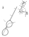
Figur 1 ein Brillengestell sowie ein Hörhilfegerät gemäß der Erfindung und -
Figur 2Figur 1 mit aufgestecktem und gebogenem Hörhilfegerät.
-
FIG. 1 a spectacle frame and a hearing aid according to the invention and -
FIG. 2 the glasses according toFIG. 1 with attached and bent hearing aid.
Das Hörhilfegerät 6 gemäß dem Ausführungsbeispiel umfasst weiterhin ein Mikrofon 9 mit einer Schalleinlassöffnung 10 zur Aufnahme eines akustischen Eingangssignals und Wandlung in ein elektrisches Signal. In einer Signalverarbeitungseinheit 11 erfolgt die Verarbeitung und frequenzabhängige Verstärkung des elektrischen Signals. Ein Hörer 12 wandelt das verarbeitete elektrische Signal zurück in ein akustisches Signal, welches über einen Schallschlauch 13 und eine Otoplastik 14 in den Gehörgang eines Hörhilfegeräteträgers geleitet wird. Zur Spannungsversorgung des Hörhilfegerätes 6 dient eine Batterie, die sich in einem Batteriefach 15 befindet. Weiterhin kann über einen Lautstärkesteller 16 die Lautstärke eingestellt oder das Hörhilfegerät 6 ausgeschaltet werden.The
Zumindest der Mittelbereich B des Hörhilfegerätes 6 ist aus einem plastisch verformbaren Material gefertigt, z.B. aus Silikonkautschuk, so dass das Gehäuse in diesem Bereich gemäß den individuellen Anforderungen des Hörbrillenträgers gebogen werden kann.At least the middle region B of the
Wie aus
Die Erfindung bietet den Vorteil, dass zur Herstellung einer Hörbrille eine handelsübliche Brille 1 verwendet werden kann, die durch die Herstellung der Hörbrille nicht beschädigt wird. Der Hörbrillenträger hat daher die Möglichkeit, verschiedene Brillen auszuprobieren und die Brille 1 nach dem Lösen des Hörhilfegerätes 6 wieder in ihren ursprünglichen Zustand (mit Tragekörpern an beiden Brillenbügel-Endstücken) zurückzuversetzen.The invention has the advantage that for the production of a pair of hearing glasses a commercial glasses 1 can be used, which is not damaged by the production of the hearing glasses. The hearing aid wearer therefore has the opportunity to try different glasses and the glasses 1 after loosening the
Die Hörbrille ist nicht auf das dargestellte Design beschränkt. Sowohl bei der Brille als auch bei dem Hörhilfegerät sind viele Variationsmöglichkeiten denkbar. Selbstverständlich kann die Hörbrille auch mit zwei Hörhilfegeräten gemäß der Erfindung (je eine am linken und am rechten Brillenbügel) zur binauralen Versorgung ausgestattet sein.The hearing glasses are not limited to the design shown. Both the glasses and the hearing aid many variations are conceivable. Of course, the hearing glasses can be equipped with two hearing aids according to the invention (one on the left and on the right temple) for binaural supply.
Claims (6)
- Hearing aid (6) which can be secured on a spectacle bow (2) of spectacles that can be worn by a wearer, with a channel (8) that extends at least partially through the hearing aid (6) and receives a bendable spectacle bow endpiece (5), characterized by a housing that is bendable at least in a subarea (B), wherein the housing and the channel (8) are designed in such a way that a metal spectacle bow endpiece (5) of conventional spectacles, in which a support body enclosing the spectacle bow endpiece (5) has been removed, can be inserted into the channel (8) and can be bent together with the housing for individually adapting the shape of the hearing aid (6) to the wearer.
- Hearing aid (6) according to Claim 1, characterized by a slender, bendable middle area (B) and a front area (A) which is enlarged compared to the middle area (B) and which has a channel opening (7) into which the spectacle bow endpiece (5) can be inserted.
- Hearing aid (6) according to Claim 1 or 2, characterized in that at least one microphone (9) for receiving an acoustic input signal is arranged in the enlarged front area (A).
- Hearing aid (6) according to one of Claims 1 to 3, characterized in that at least one earphone (12) for emitting an acoustic output signal is arranged in the enlarged front area (A).
- Hearing aid (6) according to one of Claims 1 to 4, characterized by a rear area (C) which is enlarged compared to the slender, bendable middle area (B) and in which a voltage source is arranged.
- Hearing aid (6) according to one of Claims 1 to 5, characterized by a housing made of a thermoplastic at least in the middle area (B).
Applications Claiming Priority (2)
| Application Number | Priority Date | Filing Date | Title |
|---|---|---|---|
| DE10343010 | 2003-09-17 | ||
| DE10343010A DE10343010B3 (en) | 2003-09-17 | 2003-09-17 | Hearing aid attachable to a temples |
Publications (2)
| Publication Number | Publication Date |
|---|---|
| EP1517170A1 EP1517170A1 (en) | 2005-03-23 |
| EP1517170B1 true EP1517170B1 (en) | 2010-11-03 |
Family
ID=34177795
Family Applications (1)
| Application Number | Title | Priority Date | Filing Date |
|---|---|---|---|
| EP04019231A Not-in-force EP1517170B1 (en) | 2003-09-17 | 2004-08-12 | Hearing aid attachable to a spectacle temple |
Country Status (5)
| Country | Link |
|---|---|
| US (1) | US7103192B2 (en) |
| EP (1) | EP1517170B1 (en) |
| AT (1) | ATE487157T1 (en) |
| DE (2) | DE10343010B3 (en) |
| DK (1) | DK1517170T3 (en) |
Families Citing this family (16)
| Publication number | Priority date | Publication date | Assignee | Title |
|---|---|---|---|---|
| JP4908502B2 (en) * | 2005-05-24 | 2012-04-04 | バリベル・ビー.ブイ. | Connector assembly for connecting hearing aid earpiece to eyeglass temple |
| EP1727393A1 (en) * | 2005-05-24 | 2006-11-29 | Varibel B.V. | Connector assembly for connecting an earpiece of a hearing aid to a glasses temple |
| EP2036395A1 (en) * | 2006-06-20 | 2009-03-18 | Widex A/S | Housing for a hearing aid, hearing aid, and a method of preparing a hearing aid |
| FR2910135B1 (en) * | 2006-12-14 | 2009-02-20 | Xavier Arthur Carriou | METHOD OF EXTRUSION OF A GLASS SCREEN FOR LOCATING A HEARING APPARATUS |
| DE102007028652A1 (en) * | 2007-06-21 | 2009-01-02 | Bruckhoff Apparatebau Gmbh | Hearing-aid glass e.g. contralateral routing of signal hearing-aid glass, has hearing aid fixed in and at frames and installed in or at scoop end that is designed as function scoop end, where scoop end is fitted on frame wires |
| DE102009014114B4 (en) * | 2009-03-24 | 2015-07-23 | Bruckhoff Apparatebau Gmbh | Hearing aid module and hearing glasses |
| ES2582879T3 (en) * | 2011-03-04 | 2016-09-15 | Silvietta S.R.L. | Folding glasses |
| US8918197B2 (en) | 2012-06-13 | 2014-12-23 | Avraham Suhami | Audio communication networks |
| US8543061B2 (en) | 2011-05-03 | 2013-09-24 | Suhami Associates Ltd | Cellphone managed hearing eyeglasses |
| JP5945426B2 (en) * | 2012-02-06 | 2016-07-05 | オリンパス株式会社 | Wearable equipment mounting glasses modern |
| DK3143460T3 (en) | 2014-05-12 | 2019-02-25 | Beausoleil | Glasses sleeve intended to contain part of a hearing aid |
| WO2016067754A1 (en) * | 2014-10-30 | 2016-05-06 | ソニー株式会社 | Acoustic output device |
| US20170102560A1 (en) * | 2015-10-13 | 2017-04-13 | James V. Murphy | Hearing aid holder for use with eyewear |
| US20190132683A1 (en) | 2017-10-31 | 2019-05-02 | Starkey Laboratories, Inc. | Hearing device including a sensor and a method of forming same |
| WO2021014344A1 (en) | 2019-07-21 | 2021-01-28 | Nuance Hearing Ltd. | Speech-tracking listening device |
| US10986452B1 (en) | 2019-10-15 | 2021-04-20 | Richard Hilvers | Hearing aid mounting assembly |
Family Cites Families (13)
| Publication number | Priority date | Publication date | Assignee | Title |
|---|---|---|---|---|
| US3000462A (en) * | 1954-01-18 | 1961-09-19 | Alonzo L Smith | Air-conduction hearing aid clamps |
| US2999136A (en) * | 1956-01-06 | 1961-09-05 | Telex Inc | Spectacle hearing aid |
| DE1724439U (en) * | 1956-01-25 | 1956-06-21 | Siemens Reiniger Werke Ag | ELECTRICAL AID. |
| GB1051687A (en) * | 1963-05-06 | |||
| US3382327A (en) * | 1965-05-07 | 1968-05-07 | Non Slip Temple Company Inc | Hearing aid eyeglass frame |
| US3825700A (en) * | 1973-03-02 | 1974-07-23 | Sonotone Corp | Articulated hearing aid temple and behind-the-ear hearing aid element |
| DE8336526U1 (en) * | 1983-12-20 | 1985-10-03 | Optische Werke G. Rodenstock, 8000 München | Soft-coated temple ear area |
| DE8706344U1 (en) * | 1987-05-04 | 1987-06-19 | Bruckhoff, Henning, 3000 Hannover, De | |
| DE8808620U1 (en) | 1988-07-05 | 1988-09-08 | Siemens Ag, 1000 Berlin Und 8000 Muenchen, De | |
| WO1996013136A1 (en) * | 1992-02-14 | 1996-05-02 | Da Silva Jean Pierre M | Audio-adapted eyeglass retainer |
| DE4333559A1 (en) * | 1993-10-01 | 1995-04-06 | Werner Weber | Spectacles with hearing aid |
| US6176576B1 (en) * | 1997-06-06 | 2001-01-23 | Radians, Inc. | Eyewear supported by a wearer's concha of an ear |
| EP1360871B1 (en) * | 2001-02-16 | 2005-04-27 | Audifon AG | Hearing device which can be built into the sidepiece of an eye glass |
-
2003
- 2003-09-17 DE DE10343010A patent/DE10343010B3/en not_active Expired - Fee Related
-
2004
- 2004-08-12 AT AT04019231T patent/ATE487157T1/en active
- 2004-08-12 EP EP04019231A patent/EP1517170B1/en not_active Not-in-force
- 2004-08-12 DK DK04019231.2T patent/DK1517170T3/en active
- 2004-08-12 DE DE502004011843T patent/DE502004011843D1/en active Active
- 2004-09-17 US US10/943,451 patent/US7103192B2/en not_active Expired - Fee Related
Also Published As
| Publication number | Publication date |
|---|---|
| US20050074137A1 (en) | 2005-04-07 |
| EP1517170A1 (en) | 2005-03-23 |
| DE10343010B3 (en) | 2005-04-21 |
| DK1517170T3 (en) | 2011-02-21 |
| US7103192B2 (en) | 2006-09-05 |
| DE502004011843D1 (en) | 2010-12-16 |
| ATE487157T1 (en) | 2010-11-15 |
Similar Documents
| Publication | Publication Date | Title |
|---|---|---|
| EP1517170B1 (en) | Hearing aid attachable to a spectacle temple | |
| DE102004048214B3 (en) | Universal ear piece and acoustic device with such an ear piece | |
| EP1046943B1 (en) | Listening assistance device | |
| EP1345471B1 (en) | Otoplastic for behind-the-ear hearing aids | |
| EP1876863A1 (en) | Othological device with holding device for a tragus | |
| DE1240130B (en) | Earpiece for an electronic device for the hearing impaired to be worn in the ear | |
| EP2003930B1 (en) | Hearing aid with connecting piece attached to case frame | |
| EP1967893B1 (en) | Bone conduction module for attaching on an eye glass, bone conduction hearing aid eye glass with such a modul and method for the production of the bone conduction hearing aid eye glass | |
| EP2007172B1 (en) | Sound emitting pipes with 2 component design | |
| EP1847868B1 (en) | Behind the ear hearing device including a spectacles adapter with a thin acoustic tube | |
| EP2302953B1 (en) | Bone conduction hearing aid | |
| DE10050766A1 (en) | Plastic insert that fits into ear cavity for a behind the ear hearing aid and has an inset sound tube | |
| DE102006046698B4 (en) | Sound conductor and hearing device | |
| DE10048337C1 (en) | Hearing aid device has housing worn behind ear provided with retaining element cooperating with otoplastic worn within ear | |
| EP2056625A2 (en) | Hearing aid, in particular BtE hearing aid | |
| DE102008052683B3 (en) | Hearing device and hearing aid | |
| DE102018132445A1 (en) | Otoplastic and use of an otoplastic | |
| EP1998593A1 (en) | Eartip for a hearing aid with retaining ring | |
| DE102005008319B3 (en) | In-the-ear hearing device, has auditory device housing carried in the ear | |
| DE102009014114B4 (en) | Hearing aid module and hearing glasses | |
| DE102005019994A1 (en) | Hearing aid for e.g. receiving sound information from environment, has retaining unit holding housing at ear and partially manufactured from spring elastic metallic material e.g. Nitinol, and channel designed as sound channel in unit | |
| DE102007053834B4 (en) | Hearing aid, in particular BTE hearing aid | |
| DE102015226813A1 (en) | hearing Aid | |
| DE102009016484A1 (en) | Hearing device for bad hearing person, has housing, in which signal processing components are placed, and has ear cup adapter that is fixed at housing, where ear cup adapter is provided to change outer contour | |
| EP1767048A1 (en) | Bistable expandable headband |
Legal Events
| Date | Code | Title | Description |
|---|---|---|---|
| PUAI | Public reference made under article 153(3) epc to a published international application that has entered the european phase |
Free format text: ORIGINAL CODE: 0009012 |
|
| AK | Designated contracting states |
Kind code of ref document: A1 Designated state(s): AT BE BG CH CY CZ DE DK EE ES FI FR GB GR HU IE IT LI LU MC NL PL PT RO SE SI SK TR |
|
| AX | Request for extension of the european patent |
Extension state: AL HR LT LV MK |
|
| 17P | Request for examination filed |
Effective date: 20050422 |
|
| AKX | Designation fees paid |
Designated state(s): AT BE BG CH CY CZ DE DK EE ES FI FR GB GR HU IE IT LI LU MC NL PL PT RO SE SI SK TR |
|
| 17Q | First examination report despatched |
Effective date: 20051118 |
|
| GRAP | Despatch of communication of intention to grant a patent |
Free format text: ORIGINAL CODE: EPIDOSNIGR1 |
|
| GRAS | Grant fee paid |
Free format text: ORIGINAL CODE: EPIDOSNIGR3 |
|
| GRAA | (expected) grant |
Free format text: ORIGINAL CODE: 0009210 |
|
| AK | Designated contracting states |
Kind code of ref document: B1 Designated state(s): AT BE BG CH CY CZ DE DK EE ES FI FR GB GR HU IE IT LI LU MC NL PL PT RO SE SI SK TR |
|
| REG | Reference to a national code |
Ref country code: GB Ref legal event code: FG4D Free format text: NOT ENGLISH |
|
| REG | Reference to a national code |
Ref country code: CH Ref legal event code: NV Representative=s name: SIEMENS SCHWEIZ AG Ref country code: CH Ref legal event code: EP |
|
| REG | Reference to a national code |
Ref country code: IE Ref legal event code: FG4D Free format text: LANGUAGE OF EP DOCUMENT: GERMAN |
|
| REF | Corresponds to: |
Ref document number: 502004011843 Country of ref document: DE Date of ref document: 20101216 Kind code of ref document: P |
|
| REG | Reference to a national code |
Ref country code: DK Ref legal event code: T3 |
|
| REG | Reference to a national code |
Ref country code: NL Ref legal event code: VDEP Effective date: 20101103 |
|
| REG | Reference to a national code |
Ref country code: IE Ref legal event code: FD4D |
|
| PG25 | Lapsed in a contracting state [announced via postgrant information from national office to epo] |
Ref country code: NL Free format text: LAPSE BECAUSE OF FAILURE TO SUBMIT A TRANSLATION OF THE DESCRIPTION OR TO PAY THE FEE WITHIN THE PRESCRIBED TIME-LIMIT Effective date: 20101103 Ref country code: SI Free format text: LAPSE BECAUSE OF FAILURE TO SUBMIT A TRANSLATION OF THE DESCRIPTION OR TO PAY THE FEE WITHIN THE PRESCRIBED TIME-LIMIT Effective date: 20101103 Ref country code: FI Free format text: LAPSE BECAUSE OF FAILURE TO SUBMIT A TRANSLATION OF THE DESCRIPTION OR TO PAY THE FEE WITHIN THE PRESCRIBED TIME-LIMIT Effective date: 20101103 Ref country code: SE Free format text: LAPSE BECAUSE OF FAILURE TO SUBMIT A TRANSLATION OF THE DESCRIPTION OR TO PAY THE FEE WITHIN THE PRESCRIBED TIME-LIMIT Effective date: 20101103 Ref country code: PT Free format text: LAPSE BECAUSE OF FAILURE TO SUBMIT A TRANSLATION OF THE DESCRIPTION OR TO PAY THE FEE WITHIN THE PRESCRIBED TIME-LIMIT Effective date: 20110303 Ref country code: BG Free format text: LAPSE BECAUSE OF FAILURE TO SUBMIT A TRANSLATION OF THE DESCRIPTION OR TO PAY THE FEE WITHIN THE PRESCRIBED TIME-LIMIT Effective date: 20110203 |
|
| PG25 | Lapsed in a contracting state [announced via postgrant information from national office to epo] |
Ref country code: GR Free format text: LAPSE BECAUSE OF FAILURE TO SUBMIT A TRANSLATION OF THE DESCRIPTION OR TO PAY THE FEE WITHIN THE PRESCRIBED TIME-LIMIT Effective date: 20110204 |
|
| PG25 | Lapsed in a contracting state [announced via postgrant information from national office to epo] |
Ref country code: EE Free format text: LAPSE BECAUSE OF FAILURE TO SUBMIT A TRANSLATION OF THE DESCRIPTION OR TO PAY THE FEE WITHIN THE PRESCRIBED TIME-LIMIT Effective date: 20101103 Ref country code: ES Free format text: LAPSE BECAUSE OF FAILURE TO SUBMIT A TRANSLATION OF THE DESCRIPTION OR TO PAY THE FEE WITHIN THE PRESCRIBED TIME-LIMIT Effective date: 20110214 Ref country code: CZ Free format text: LAPSE BECAUSE OF FAILURE TO SUBMIT A TRANSLATION OF THE DESCRIPTION OR TO PAY THE FEE WITHIN THE PRESCRIBED TIME-LIMIT Effective date: 20101103 Ref country code: IE Free format text: LAPSE BECAUSE OF FAILURE TO SUBMIT A TRANSLATION OF THE DESCRIPTION OR TO PAY THE FEE WITHIN THE PRESCRIBED TIME-LIMIT Effective date: 20101103 |
|
| PG25 | Lapsed in a contracting state [announced via postgrant information from national office to epo] |
Ref country code: RO Free format text: LAPSE BECAUSE OF FAILURE TO SUBMIT A TRANSLATION OF THE DESCRIPTION OR TO PAY THE FEE WITHIN THE PRESCRIBED TIME-LIMIT Effective date: 20101103 Ref country code: PL Free format text: LAPSE BECAUSE OF FAILURE TO SUBMIT A TRANSLATION OF THE DESCRIPTION OR TO PAY THE FEE WITHIN THE PRESCRIBED TIME-LIMIT Effective date: 20101103 Ref country code: SK Free format text: LAPSE BECAUSE OF FAILURE TO SUBMIT A TRANSLATION OF THE DESCRIPTION OR TO PAY THE FEE WITHIN THE PRESCRIBED TIME-LIMIT Effective date: 20101103 |
|
| PLBE | No opposition filed within time limit |
Free format text: ORIGINAL CODE: 0009261 |
|
| STAA | Information on the status of an ep patent application or granted ep patent |
Free format text: STATUS: NO OPPOSITION FILED WITHIN TIME LIMIT |
|
| 26N | No opposition filed |
Effective date: 20110804 |
|
| PGFP | Annual fee paid to national office [announced via postgrant information from national office to epo] |
Ref country code: DK Payment date: 20110822 Year of fee payment: 8 |
|
| REG | Reference to a national code |
Ref country code: DE Ref legal event code: R097 Ref document number: 502004011843 Country of ref document: DE Effective date: 20110804 |
|
| PG25 | Lapsed in a contracting state [announced via postgrant information from national office to epo] |
Ref country code: IT Free format text: LAPSE BECAUSE OF FAILURE TO SUBMIT A TRANSLATION OF THE DESCRIPTION OR TO PAY THE FEE WITHIN THE PRESCRIBED TIME-LIMIT Effective date: 20101103 |
|
| BERE | Be: lapsed |
Owner name: SIEMENS AUDIOLOGISCHE TECHNIK G.M.B.H. Effective date: 20110831 |
|
| PG25 | Lapsed in a contracting state [announced via postgrant information from national office to epo] |
Ref country code: MC Free format text: LAPSE BECAUSE OF NON-PAYMENT OF DUE FEES Effective date: 20110831 |
|
| PG25 | Lapsed in a contracting state [announced via postgrant information from national office to epo] |
Ref country code: BE Free format text: LAPSE BECAUSE OF NON-PAYMENT OF DUE FEES Effective date: 20110831 |
|
| PGFP | Annual fee paid to national office [announced via postgrant information from national office to epo] |
Ref country code: GB Payment date: 20120809 Year of fee payment: 9 |
|
| REG | Reference to a national code |
Ref country code: AT Ref legal event code: MM01 Ref document number: 487157 Country of ref document: AT Kind code of ref document: T Effective date: 20110812 |
|
| PGFP | Annual fee paid to national office [announced via postgrant information from national office to epo] |
Ref country code: FR Payment date: 20120823 Year of fee payment: 9 |
|
| PG25 | Lapsed in a contracting state [announced via postgrant information from national office to epo] |
Ref country code: AT Free format text: LAPSE BECAUSE OF NON-PAYMENT OF DUE FEES Effective date: 20110812 |
|
| PGFP | Annual fee paid to national office [announced via postgrant information from national office to epo] |
Ref country code: DE Payment date: 20121019 Year of fee payment: 9 Ref country code: CH Payment date: 20121113 Year of fee payment: 9 |
|
| PG25 | Lapsed in a contracting state [announced via postgrant information from national office to epo] |
Ref country code: LU Free format text: LAPSE BECAUSE OF NON-PAYMENT OF DUE FEES Effective date: 20110812 Ref country code: CY Free format text: LAPSE BECAUSE OF EXPIRATION OF PROTECTION Effective date: 20101103 |
|
| PG25 | Lapsed in a contracting state [announced via postgrant information from national office to epo] |
Ref country code: TR Free format text: LAPSE BECAUSE OF FAILURE TO SUBMIT A TRANSLATION OF THE DESCRIPTION OR TO PAY THE FEE WITHIN THE PRESCRIBED TIME-LIMIT Effective date: 20101103 |
|
| PG25 | Lapsed in a contracting state [announced via postgrant information from national office to epo] |
Ref country code: HU Free format text: LAPSE BECAUSE OF FAILURE TO SUBMIT A TRANSLATION OF THE DESCRIPTION OR TO PAY THE FEE WITHIN THE PRESCRIBED TIME-LIMIT Effective date: 20101103 |
|
| REG | Reference to a national code |
Ref country code: DK Ref legal event code: EBP Effective date: 20130831 Ref country code: CH Ref legal event code: PL |
|
| GBPC | Gb: european patent ceased through non-payment of renewal fee |
Effective date: 20130812 |
|
| PG25 | Lapsed in a contracting state [announced via postgrant information from national office to epo] |
Ref country code: LI Free format text: LAPSE BECAUSE OF NON-PAYMENT OF DUE FEES Effective date: 20130831 Ref country code: CH Free format text: LAPSE BECAUSE OF NON-PAYMENT OF DUE FEES Effective date: 20130831 Ref country code: DE Free format text: LAPSE BECAUSE OF NON-PAYMENT OF DUE FEES Effective date: 20140301 |
|
| REG | Reference to a national code |
Ref country code: DE Ref legal event code: R119 Ref document number: 502004011843 Country of ref document: DE Effective date: 20140301 |
|
| REG | Reference to a national code |
Ref country code: FR Ref legal event code: ST Effective date: 20140430 |
|
| PG25 | Lapsed in a contracting state [announced via postgrant information from national office to epo] |
Ref country code: GB Free format text: LAPSE BECAUSE OF NON-PAYMENT OF DUE FEES Effective date: 20130812 |
|
| PG25 | Lapsed in a contracting state [announced via postgrant information from national office to epo] |
Ref country code: FR Free format text: LAPSE BECAUSE OF NON-PAYMENT OF DUE FEES Effective date: 20130902 |
|
| PG25 | Lapsed in a contracting state [announced via postgrant information from national office to epo] |
Ref country code: DK Free format text: LAPSE BECAUSE OF NON-PAYMENT OF DUE FEES Effective date: 20130831 |