EP2056447B1 - Amplitudenmodulierter Sender und Modulationsverfahren damit - Google Patents
Amplitudenmodulierter Sender und Modulationsverfahren damit Download PDFInfo
- Publication number
- EP2056447B1 EP2056447B1 EP08011803.7A EP08011803A EP2056447B1 EP 2056447 B1 EP2056447 B1 EP 2056447B1 EP 08011803 A EP08011803 A EP 08011803A EP 2056447 B1 EP2056447 B1 EP 2056447B1
- Authority
- EP
- European Patent Office
- Prior art keywords
- signal
- gain controlling
- unit
- detecting
- transmitter
- Prior art date
- Legal status (The legal status is an assumption and is not a legal conclusion. Google has not performed a legal analysis and makes no representation as to the accuracy of the status listed.)
- Active
Links
Images


Classifications
-
- H—ELECTRICITY
- H03—ELECTRONIC CIRCUITRY
- H03C—MODULATION
- H03C1/00—Amplitude modulation
- H03C1/36—Amplitude modulation by means of semiconductor device having at least three electrodes
Definitions
- the present invention relates to an AM (Amplitude-Modulated) transmitter and to a modulation method using the same.
- a conventional AM transmitter is disclosed in, for example, Unexamined Japanese Utility Model Application KOKAI Publication No. S63-72942 (page 3-4, FIG. 1 ) which is configured to modulate a transmitting signal to be outputted and to detect a nonlinear distortion by signal detection and to make variable a level of an input signal to a power amplifier using a gain controller for feedback.
- the disclosed AM transmitter includes a directional coupler 51, a modulator 52, a detector 53, a detected output amplifier 54, an automatic gain controller 55, and a power amplifier 56.
- the directional coupler 51 is configured to make a carrier wave component fed by the power amplifier 56 branch and to supply the branched carrier wave to the modulator 52.
- the modulator 52 is configured to amplitude-modulate, using a modulating signal, the carrier wave component supplied from the modulator 52.
- the detector 53 is configured to detect the modulated signal which is amplitude-modulated by the modulator 52.
- the detected output amplifier 54 is configured to amplify a detecting signal resulting from the detection by the detector 53 up to a specified level and to feed the amplified detecting signal to the automatic gain controller 55.
- the automatic gain controller 55 is configured to control a level of a carrier wave of an input signal to be inputted to the power amplifier 56 according to an output from the detected output amplifier 54.
- the automatic gain controller 55 to perform modulation is mounted in the front stage of the power amplifier 56.
- the modulation distortion of a transmitted output depends greatly on linearity of the power amplifier 56.
- an output power of 4 W is required. That is, it is necessary that input-output power characteristics provided by the power amplifier 56 exhibit linearity till its output power reaches 4W.
- the power amplifier 56 since the power amplifier 56 has a nonlinear distortion, in order to obtain an output power of 4W, the power amplifier 56 that can provide an output power of, for example, 8W is required.
- the power amplifier 56 providing large peak power is required. If the power amplifier 56 providing such large peak power is applied to the AM transmitter, its miniaturization is made difficult and, in a small-sized AM transmitter in particular, the use of such the power amplifier causes disadvantages.
- the AM transmitter disclosed in the Unexamined Japanese Utility Model Application KOKAI Publication No. S63-72942 , by modulating a carrier wave component of a transmitting signal and by performing detection, a difference among nonlinear components in the power amplifier 56 is calculated and by controlling a level of a carrier wave to be inputted to the power amplifier 56, the nonlinear distortion is compensated for.
- the modulator 52 modulates a carrier wave made to branch by the directional coupler 51, and furthermore, the automatic gain controller 55 modulates a carrier wave of an input signal. This causes complicated configurations of the AM transmitter.
- the thigh frequency power amplifier includes high frequency amplifier 110 being composed by amplificating stages 111, 112, and 113.
- the amplification stages 111 to 113 are supplied with optimum bias voltages VB1, VB2 and VB3, respectively from a bias circuit 121 in order to power amplify signals.
- US 4412337 discloses a power modulating a signal by a PIN diode amplifier 16.
- an object of the present invention is to provide an AM transmitter capable of improving a modulation distortion and a modulation method to be executed by the AM transmitter.
- the AM transmitter of the present invention is capable of improving a modulation distortion.
- the AM transmitter of an embodiment of the present invention is described below by referring to drawings.
- the configurations of the AM transmitter of the embodiment are shown in FIG. 1 .
- the AM transmitter 1 of the embodiment of the present invention includes an amplifier (in FIG. 1 , referred to as "PRE DRIVE") 11, an amplifier (in FIG. 1 , referred to as “DRIVE AMP") 12, a power amplifier (in FIG.1 , referred to as “PWR AMP") 13, LPFs (Low Pass Filters) 14, 16, and 19, an antenna switch (in FIG. 1 , referred to as "ANT SW") 15, an antenna 17, a power detector (in FIG. 1 , referred to as "POWER DET”) 18, an adder 20 and an APC (Automatic Power Control) amplifier (in FIG. 1 , referred to as "APC AMP”) 21.
- An amplifier unit 10 includes the amplifiers 12 and 13.
- the amplifiers 11 and 12 are used to excite the power amplifier 13 mounted in the final stage of the AM transmitter 1 which is required to obtain a specified antenna output.
- the amplifier 11 is supplied with a carrier wave of an input signal and is configured to amplify the supplied carrier wave of the input signal and outputs the amplifying signal S11 to the amplifier 12.
- the amplifier 12 is supplied, by the APC amplifier 21 described later, with a gain controlling signal S21 to control a gain and is configured to amplitude-modulate the signal S11 output from the amplifier 11 according to the gain controlling signal S21 and to amplify the amplitude-modulated signal and to output the amplified signal S12 to the power amplifier 13.
- the power amplifier 13 is supplied, by the APC amplifier, with the gain controlling signal S21 and is configured to modulate the signal S12 outputted by the amplifier 12 by the gain controlling signal S21 and to power-amplify the modulated signal and to output the power-amplified signal to the LPF 14 as a transmitting signal S 13.
- the LPF 14 has a cut-off frequency set in advance and is a filter which removes a component having a frequency being higher than the cut-off frequency from the transmitted signal S 13 outputted from the power amplifier 13 and outputs a transmitting signal S 14 from which a high-frequency component had been removed to the antenna switch 15.
- the antenna switch 15 is a switch to select either of a receiving signal or a transmitting signal to be outputted.
- the transmitting signal S 14 outputted by the LPF 14 is selected and outputted to the LPF 16.
- the LPF 16 has a cut-off frequency set in advance and is a filter which removes a component having a frequency being higher than the cut-off frequency from the signal S 14 selected and outputted by the antenna switch 15 and outputs a transmitting signal S16 obtained by removing a high-frequency component to the antenna 17.
- the antenna 17 sends out the transmitting signal S16 outputted by the LPF 16 as a radio wave.
- the power detector 18 detects an amplitude-modulated component obtained by removing a carrier wave component from the transmitting signal S16 outputted by the LPF 16 and feeds a detecting signal S18 being an amplitude-modulated component of the transmitted signal S16 to the LPF 19.
- the LPF 19 has a cut-off frequency set in advance and is a filter which removes a component having a frequency being higher than the cut-off frequency from the detected signal S 18 outputted by the power detector 18 and outputs the signal obtained by removing a high-frequency component to the APC amplifier 21 as a detecting signal S 19.
- a cut-off frequency is set to the LPF 19 that follows a change of the detecting signal S18.
- the adder 20 adds a modulated signal Smod to a preset power reference signal Sref and feeds the added signal S20 to the APC amplifier 21.
- the APC amplifier 21 outputs a gain controlling signal S21 to the amplifier 12 and power amplifier 13 and controls gains of the amplifier 12 and the power amplifier 13.
- the APC amplifier 21 is supplied with the signal S20 from the adder 20 and with the detecting signal S 19 from the LPF 19.
- the APC amplifier 21 compares the detecting signal S19 outputted from the LPF 19 with the signal S20 to improve nonlinear distortion of the power amplifier 13.
- the carrier wave of an input signal is fed to the amplifier 11 which amplifies the carrier wave of the input signal and outputs the signal S11 to the amplifier 12.
- the amplifier 12 modulates the signal S11 outputted from the amplifier 11 according to the gain controlling signal S21 outputted from the APC amplifier 21 and amplifies the modulated signal and outputs the amplified signal S12 to the power amplifier 13.
- the power amplifier 13 modulates the signal S12 outputted from the amplifier 12 according to the gain controlling signal S21 outputted from the APC amplifier 21 and amplifies the modulated signal to outputs the signal to the LPF 14.
- the LPF 14 outputs the transmitting signal S 14 obtained by removing high-frequency components from the transmitting signal S 13 to the antenna switch 15 and the antenna 17 outputs a transmitting signal S16 obtained by removing high-frequency components from a transmitting signal S14 selected and outputted by the antenna switch 15 as a radio wave.
- the power detector 18 outputs a detecting signal S 18 being an amplitude-modulated component obtained by removing a carrier wave component from the transmitting signal S16 to the LPF 19 and the LPF 19 removes a high-frequency component from the detecting signal S 18 and outputs a detecting signal S 19 to the APC amplifier 21.
- the cut-off frequency of the LPF 19 is set at a frequency that follows a change of the detecting signal S 18. Therefore, the LPF 19 outputs the detecting signal S 19 obtained by removing only the unwanted high-frequency noise component contained in the detecting signal S 18 to the APC amplifier 21.
- the adder 20 adds the modulated signal Smod to the pre-set power reference signal Sref and outputs an adder signal S20 obtained by the addition to the APC amplifier 21.
- the APC amplifier 21 compares a level of the signal S20 fed from the adder 20 with a level of the detected signal S 19 outputted by the LPF 19 that follows the detected signal S18 and, based on the comparison result, generates a gain controlling signal S21 that makes a difference between a level of the signal S20 and a level of the detected signal S 19 that followed the detected signal S 18 approach zero. Then, the APC amplifier 21 sets a level of the gain controlling signal S21 and outputs the level to the amplifier 12 and the power amplifier 13.
- an amplitude-modulated signal is outputted as a transmitting signal via the power amplifier 56 having a nonlinear distortion characteristic.
- the amplitude-modulated signal is affected by the nonlinear distortion characteristic of the power amplifier 56.
- the modulation degree becomes small due to the nonlinear distortion characteristic of the power amplifier 56 and, as shown by the characteristic line A2 in FIG. 2B , as the modulation degree becomes larger, the modulation distortion becomes large.
- the amplifier 12 and the power amplifier 13 amplitude-modulate and amplify the carrier wave according to the gain controlling signal S21 fed from the APC amplifier 21.
- an operation of variable gain amplification of the power amplifier 13 itself serves as an amplitude-modulation and power amplification.
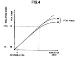
- a curve of the modulation degree in the AM transmitter 1 of the embodiment of the present invention is linear relative to modulation inputs till the degree reaches 100%.
- the modulation distortion remains almost unchanged till the modulation degree reaches 100%.
- both the detecting signal and modulating signal are fed to the APC amplifier 21 which compares the fed detecting signal with the modulating signal and provides an amplification control signal that makes the difference approach zero to the power amplifier 13.
- the modulation degree does not depend on a nonlinear distortion characteristic of the power amplifier 13 and, even when signals are deeply modulated, no increase occurs in the modulation distortion, resulting in the improvement of the modulation distortion.
- the amplitude-modulation is performed by the amplifier 12 and power amplifier 13, however, the amplitude-modulation may be performed only by the power amplifier according to specifications of a transmitter and performance of a power amplifier. Furthermore, the number of stages of the amplifiers mounted in the front stage of the power amplifier 13 can be changed as appropriate.
Landscapes
- Transmitters (AREA)
Claims (5)
- Ein AM (amplitudenmodulierter)-Sender (1), umfassend:eine Verstärkungseinheit (10), die konfiguriert ist zum Ausgeben eines Sendesignals,eine Erfassungssignal-Erzeugungseinheit (18) zum Erfassen des durch die Verstärkungseinheit (10) ausgegebenen Sendesignals und zum Erzeugen eines Erfassungssignals, undeine Verstärkungs-Steuereinheit (21), zu der ein Modulationssignal zugeführt wird, zum Vergleichen des Pegels des durch die Erfassungssignal-Erzeugungseinheit (18) erzeugten Erfassungssignals mit dem Pegel des Modulationssignals sowie, basierend auf dem Vergleichsergebnis, zum Erzeugen eines Verstärkungssteuersignals und zum Zuführen des erzeugten Verstärkungssteuersignals zu der Verstärkungseinheit (10),dadurch gekennzeichnet, dass:die Verstärkungseinheit (10) weiterhin konfiguriert ist zum Erhalten des eine Verstärkung angebenden Verstärkungssteuersignals, zum Amplitudenmodulieren einer Trägerwelle durch das Verstärkungssteuersignal, zum Leistungsverstärken des modulierten Signals in Übereinstimmung mit dem zugeführten Verstärkungssteuersignal und zum Ausgeben des amplitudenmodulierten und leistungsverstärkten Sendesignals.
- AM-Sender (1) nach Anspruch 1, dadurch gekennzeichnet, dass die Verstärkungssteuereinheit (21) den Pegel des durch die Erfassungssignal-Erzeugungseinheit erzeugten Erfassungssignals mit dem Pegel eines Modulationssignals vergleicht und basierend auf dem Vergleichsergebnis ein Verstärkungssteuersignal erzeugt, das dafür sorgt, dass sich eine Differenz zwischen dem Pegel des Modulationssignals und dem Pegel des Erfassungssignals an null annähert.
- AM-Sender (1) nach Anspruch 2, dadurch gekennzeichnet, dass die Verstärkungseinheit (10) eine erste Verstärkungseinheit (12) und eine zweite Verstärkungseinheit (13) umfasst, wobei die erste Verstärkungseinheit (12) die Trägerwelle in Übereinstimmung mit dem durch die Verstärkungssteuereinheit (21) erzeugten Verstärkungssteuersignal verstärkt und ein erstes Sendesignal ausgibt und wobei die zweite Verstärkungseinheit (13) das erste Sendesignal basierend auf dem durch die Verstärkungssteuereinheit (21) erzeugten Verstärkungssteuersignal moduliert und verstärkt und ein zweites Sendesignal ausgibt, wobei die Erfassungssignal-Erzeugungseinheit (18) das durch die zweite Verstärkungseinheit (13) ausgegebene zweite Sendesignal erfasst und ein Erfassungssignal erzeugt.
- AM-Sender (1) nach Anspruch 3, dadurch gekennzeichnet, dass Tiefpassfilter zwischen der zweiten Verstärkungseinheit (13) und der Erfassungssignal-Erzeugungseinheit (18) und zwischen der Erfassungssignal-Erzeugungseinheit (18) und der Verstärkungssteuereinheit (21) vorgesehen sind.
- Modulationsverfahren für die Ausführung durch einen AM-Sender, der eine Verstärkungseinheit (10), eine Erfassungssignal-Erzeugungseinheit (18) und eine Verstärkungssteuereinheit (21) aufweist, umfassend:einen Ausgabeschritt der Verstärkungseinheit (10) zum Ausgeben eines Sendesignals,einen Erzeugungsschritt der Erfassungssignal-Erzeugungseinheit (18) zum Erfassen des Sendesignals und zum Erzeugen eines Erfassungssignals, undeinen Steuerschritt der Verstärkungssteuereinheit (21), zu der ein Modulationssignal zugeführt wird, zum Modulieren der Trägerwelle und zum Vergleichen des Pegels des erzeugten Erfassungssignals mit dem Pegel des Modulationssignals sowie, basierend auf dem Vergleichsergebnis, zum Erzeugen eines Verstärkungssteuersignals und, basierend auf dem Verstärkungssteuersignal, zum Steuern der Verstärkung,dadurch gekennzeichnet, dassder Ausgabeschritt der Verstärkungseinheit (10) weiterhin das Amplitudenmodulieren einer Trägerwelle durch das eine Verstärkung angebende Verstärkungssteuersignal, das Leistungsverstärken des modulierten Signals in Übereinstimmung mit den Verstärkungssteuersignal und das Ausgeben des amplitudenmodulierten und leistungsverstärkten Sendesignals umfasst.
Applications Claiming Priority (1)
| Application Number | Priority Date | Filing Date | Title |
|---|---|---|---|
| JP2007284132A JP4867891B2 (ja) | 2007-10-31 | 2007-10-31 | Am送信機及びその変調方法 |
Publications (3)
| Publication Number | Publication Date |
|---|---|
| EP2056447A2 EP2056447A2 (de) | 2009-05-06 |
| EP2056447A3 EP2056447A3 (de) | 2009-12-23 |
| EP2056447B1 true EP2056447B1 (de) | 2014-11-19 |
Family
ID=40364457
Family Applications (1)
| Application Number | Title | Priority Date | Filing Date |
|---|---|---|---|
| EP08011803.7A Active EP2056447B1 (de) | 2007-10-31 | 2008-06-30 | Amplitudenmodulierter Sender und Modulationsverfahren damit |
Country Status (4)
| Country | Link |
|---|---|
| US (1) | US8554160B2 (de) |
| EP (1) | EP2056447B1 (de) |
| JP (1) | JP4867891B2 (de) |
| CA (1) | CA2636481C (de) |
Family Cites Families (32)
| Publication number | Priority date | Publication date | Assignee | Title |
|---|---|---|---|---|
| US3961287A (en) | 1975-04-16 | 1976-06-01 | Prf, Inc. | Amplitude modulated transmitter |
| US4412337A (en) | 1981-11-04 | 1983-10-25 | Motorola Inc. | Power amplifier and envelope correction circuitry |
| US4708701A (en) * | 1986-09-08 | 1987-11-24 | Borg-Warner Automotive, Inc. | Chain-belt |
| JPS6372942U (de) | 1986-10-29 | 1988-05-16 | ||
| JPH07112163B2 (ja) * | 1989-11-06 | 1995-11-29 | 三菱電機株式会社 | リニア変調無線送信装置 |
| US5432473A (en) * | 1993-07-14 | 1995-07-11 | Nokia Mobile Phones, Limited | Dual mode amplifier with bias control |
| US5892396A (en) * | 1997-07-31 | 1999-04-06 | Motorola, Inc. | Method and apparatus for controlling gain of a power amplifier |
| US6519293B1 (en) * | 1998-06-03 | 2003-02-11 | Mitsubishi Denki Kabushiki Kaisha | Radio transmitter and radio communication method |
| JP2000209294A (ja) | 1998-12-30 | 2000-07-28 | Texas Instr Inc <Ti> | 振幅位相変調信号を供給するための回路と方法 |
| WO2001065682A2 (de) * | 2000-03-03 | 2001-09-07 | Siemens Aktiengesellschaft | Verfahren und sendeschaltung zur erzeugung eines sendesignals |
| JP2002111397A (ja) * | 2000-09-29 | 2002-04-12 | Sony Corp | 歪補償装置及び歪補償方法 |
| AU2002213966A1 (en) * | 2000-10-18 | 2002-04-29 | Telefonaktiebolaget Lm Ericsson (Publ) | Communications systems |
| WO2002084935A1 (en) * | 2001-04-17 | 2002-10-24 | Nokia Corporation | Methods for determining the gains of different carriers, radio transmission units and modules for such units |
| FR2826205B1 (fr) * | 2001-06-13 | 2003-12-05 | Matra Nortel Communications | Procede de modulation de l'amplitude d'un signal radiofrequence, et dispositif pour sa mise en oeuvre |
| US6956914B2 (en) * | 2001-09-19 | 2005-10-18 | Gennum Corporation | Transmit amplitude independent adaptive equalizer |
| GB2412512B (en) * | 2002-05-31 | 2005-11-16 | Renesas Tech Corp | A communication semiconductor integrated circuit, a wireless communication apparatus, and a loop gain calibration method |
| GB2412513B (en) * | 2002-05-31 | 2006-03-08 | Renesas Tech Corp | Apparatus for radio telecommunication system and method of building up output power |
| EP1450479B1 (de) * | 2003-02-20 | 2012-03-28 | Sony Ericsson Mobile Communications AB | Effizienter Modulation von Hochfrequenzsignalen |
| US7418244B2 (en) * | 2003-08-04 | 2008-08-26 | Analog Devices, Inc. | Radio transmitter with accurate power control |
| JP2005094282A (ja) * | 2003-09-17 | 2005-04-07 | Renesas Technology Corp | 通信用半導体集積回路 |
| EP1526651B1 (de) * | 2003-10-23 | 2006-05-24 | Sony Ericsson Mobile Communications AB | Zusätzliche Regelung des Referenzsignals der Automatischen Leistungsregelung in einem mobilen Endgerät |
| US7215972B2 (en) * | 2003-12-09 | 2007-05-08 | Freescale Semiconductor, Inc. | Adaptive transmit power control system |
| US20050208907A1 (en) * | 2004-03-18 | 2005-09-22 | Ryo Yamazaki | Detecting and maintaining linearity in a power amplifier system through envelope power comparisons |
| JP4388849B2 (ja) * | 2004-04-30 | 2009-12-24 | アイコム株式会社 | 送信機 |
| JP2006013566A (ja) | 2004-06-22 | 2006-01-12 | Renesas Technology Corp | 高周波電力増幅用電子部品 |
| TWM278180U (en) * | 2004-09-14 | 2005-10-11 | Inventec Appliances Corp | Circuit structure of mobile phone capable of dynamically controlling power |
| US7193462B2 (en) * | 2005-03-22 | 2007-03-20 | Powerwave Technologies, Inc. | RF power amplifier system employing an analog predistortion module using zero crossings |
| JP4750463B2 (ja) | 2005-05-11 | 2011-08-17 | ルネサスエレクトロニクス株式会社 | 高周波電力増幅器およびそれを用いた送信器および移動体通信端末 |
| US7542741B2 (en) * | 2006-01-31 | 2009-06-02 | Skyworks Solutions, Inc. | System and method for power mapping to compensate for power amplifier gain control variations |
| US7873332B2 (en) * | 2006-12-06 | 2011-01-18 | Broadcom Corporation | Method and system for mitigating a voltage standing wave ratio |
| US7466195B2 (en) * | 2007-05-18 | 2008-12-16 | Quantance, Inc. | Error driven RF power amplifier control with increased efficiency |
| US7783269B2 (en) * | 2007-09-20 | 2010-08-24 | Quantance, Inc. | Power amplifier controller with polar transmitter |
-
2007
- 2007-10-31 JP JP2007284132A patent/JP4867891B2/ja active Active
-
2008
- 2008-05-30 US US12/130,709 patent/US8554160B2/en active Active
- 2008-06-27 CA CA2636481A patent/CA2636481C/en active Active
- 2008-06-30 EP EP08011803.7A patent/EP2056447B1/de active Active
Also Published As
| Publication number | Publication date |
|---|---|
| CA2636481C (en) | 2014-06-03 |
| JP4867891B2 (ja) | 2012-02-01 |
| EP2056447A3 (de) | 2009-12-23 |
| EP2056447A2 (de) | 2009-05-06 |
| JP2009111887A (ja) | 2009-05-21 |
| US20090111396A1 (en) | 2009-04-30 |
| US8554160B2 (en) | 2013-10-08 |
| CA2636481A1 (en) | 2009-04-30 |
Similar Documents
| Publication | Publication Date | Title |
|---|---|---|
| US5861777A (en) | Method and apparatus for compensation of phase distortion in power amplifiers | |
| US5886572A (en) | Method and apparatus for reducing distortion in a power amplifier | |
| EP2304871B1 (de) | Schaltleistungsverstärker und verfahren zu seiner steuerung | |
| US6252455B1 (en) | Method and apparatus for efficient signal amplification | |
| EP2055012B1 (de) | System und verfahren zur steuerung eines korrekturfeedback- leistungsverstärkers mit geringer verzögerung | |
| US7734263B2 (en) | Transmission circuit and communication device | |
| JP4714184B2 (ja) | 無線信号増幅装置 | |
| KR20070037704A (ko) | 포락선 제거와 복구를 통한 신호 증폭 방법 및 시스템 | |
| WO2007040826A3 (en) | A radio frequency power amplifier circuit and method | |
| US8442459B2 (en) | Transmitter and communication apparatus using the same | |
| US7583940B2 (en) | Transmission circuit and communication apparatus employing the same | |
| KR100798399B1 (ko) | Tdd 방식의 이동통신시스템에서의 신호 송수신장치 | |
| US11115260B2 (en) | Signal compensation device | |
| JP2007053540A (ja) | ドハティ型増幅器 | |
| US7391261B2 (en) | Enhanced bandwidth envelope elimination and restoration | |
| US7095988B2 (en) | Apparatus for linear transmitter with improved loop gain stabilization | |
| CA2636481C (en) | Am transmitter and modulation method using same | |
| US20110136450A1 (en) | Power circuit and radio communication circuit using same and method of operating a circuit | |
| US20020079980A1 (en) | Apparatus comprising a phase and amplitude-modulated signal transmitter, method implemented in such apparatus | |
| EP1130817A3 (de) | Optischer Modulator mit selbst-optimierten HF-EingangsTreiberschaltung | |
| JP2001332985A (ja) | 送信電力制御回路及びこれを用いた送信機 | |
| KR100327863B1 (ko) | 디지털신호처리 연산을 이용한 알에프 대역 무선통신송신단의 출력 안정화, 극대화 및 비선형왜곡 보상 방법및 알에프 모듈 | |
| JPH07336147A (ja) | 高周波出力増幅器 | |
| US20080261541A1 (en) | Method and Device for Amplifying an Amplitude and Phase Modulated Electric Signal | |
| US7050770B1 (en) | Linearized amplifier having a bypass circuit |
Legal Events
| Date | Code | Title | Description |
|---|---|---|---|
| PUAI | Public reference made under article 153(3) epc to a published international application that has entered the european phase |
Free format text: ORIGINAL CODE: 0009012 |
|
| 17P | Request for examination filed |
Effective date: 20080630 |
|
| AK | Designated contracting states |
Kind code of ref document: A2 Designated state(s): AT BE BG CH CY CZ DE DK EE ES FI FR GB GR HR HU IE IS IT LI LT LU LV MC MT NL NO PL PT RO SE SI SK TR |
|
| AX | Request for extension of the european patent |
Extension state: AL BA MK RS |
|
| PUAL | Search report despatched |
Free format text: ORIGINAL CODE: 0009013 |
|
| AK | Designated contracting states |
Kind code of ref document: A3 Designated state(s): AT BE BG CH CY CZ DE DK EE ES FI FR GB GR HR HU IE IS IT LI LT LU LV MC MT NL NO PL PT RO SE SI SK TR |
|
| AX | Request for extension of the european patent |
Extension state: AL BA MK RS |
|
| 17Q | First examination report despatched |
Effective date: 20100625 |
|
| AKX | Designation fees paid |
Designated state(s): AT BE BG CH CY CZ DE DK EE ES FI FR GB GR HR HU IE IS IT LI LT LU LV MC MT NL NO PL PT RO SE SI SK TR |
|
| GRAP | Despatch of communication of intention to grant a patent |
Free format text: ORIGINAL CODE: EPIDOSNIGR1 |
|
| INTG | Intention to grant announced |
Effective date: 20140722 |
|
| GRAS | Grant fee paid |
Free format text: ORIGINAL CODE: EPIDOSNIGR3 |
|
| GRAA | (expected) grant |
Free format text: ORIGINAL CODE: 0009210 |
|
| AK | Designated contracting states |
Kind code of ref document: B1 Designated state(s): AT BE BG CH CY CZ DE DK EE ES FI FR GB GR HR HU IE IS IT LI LT LU LV MC MT NL NO PL PT RO SE SI SK TR |
|
| REG | Reference to a national code |
Ref country code: GB Ref legal event code: FG4D |
|
| REG | Reference to a national code |
Ref country code: CH Ref legal event code: EP |
|
| REG | Reference to a national code |
Ref country code: AT Ref legal event code: REF Ref document number: 697524 Country of ref document: AT Kind code of ref document: T Effective date: 20141215 |
|
| REG | Reference to a national code |
Ref country code: IE Ref legal event code: FG4D |
|
| REG | Reference to a national code |
Ref country code: DE Ref legal event code: R096 Ref document number: 602008035417 Country of ref document: DE Effective date: 20141231 |
|
| REG | Reference to a national code |
Ref country code: NL Ref legal event code: VDEP Effective date: 20141119 |
|
| REG | Reference to a national code |
Ref country code: AT Ref legal event code: MK05 Ref document number: 697524 Country of ref document: AT Kind code of ref document: T Effective date: 20141119 |
|
| REG | Reference to a national code |
Ref country code: LT Ref legal event code: MG4D |
|
| PG25 | Lapsed in a contracting state [announced via postgrant information from national office to epo] |
Ref country code: PT Free format text: LAPSE BECAUSE OF FAILURE TO SUBMIT A TRANSLATION OF THE DESCRIPTION OR TO PAY THE FEE WITHIN THE PRESCRIBED TIME-LIMIT Effective date: 20150319 Ref country code: ES Free format text: LAPSE BECAUSE OF FAILURE TO SUBMIT A TRANSLATION OF THE DESCRIPTION OR TO PAY THE FEE WITHIN THE PRESCRIBED TIME-LIMIT Effective date: 20141119 Ref country code: FI Free format text: LAPSE BECAUSE OF FAILURE TO SUBMIT A TRANSLATION OF THE DESCRIPTION OR TO PAY THE FEE WITHIN THE PRESCRIBED TIME-LIMIT Effective date: 20141119 Ref country code: IS Free format text: LAPSE BECAUSE OF FAILURE TO SUBMIT A TRANSLATION OF THE DESCRIPTION OR TO PAY THE FEE WITHIN THE PRESCRIBED TIME-LIMIT Effective date: 20150319 Ref country code: NO Free format text: LAPSE BECAUSE OF FAILURE TO SUBMIT A TRANSLATION OF THE DESCRIPTION OR TO PAY THE FEE WITHIN THE PRESCRIBED TIME-LIMIT Effective date: 20150219 Ref country code: NL Free format text: LAPSE BECAUSE OF FAILURE TO SUBMIT A TRANSLATION OF THE DESCRIPTION OR TO PAY THE FEE WITHIN THE PRESCRIBED TIME-LIMIT Effective date: 20141119 Ref country code: LT Free format text: LAPSE BECAUSE OF FAILURE TO SUBMIT A TRANSLATION OF THE DESCRIPTION OR TO PAY THE FEE WITHIN THE PRESCRIBED TIME-LIMIT Effective date: 20141119 |
|
| PG25 | Lapsed in a contracting state [announced via postgrant information from national office to epo] |
Ref country code: AT Free format text: LAPSE BECAUSE OF FAILURE TO SUBMIT A TRANSLATION OF THE DESCRIPTION OR TO PAY THE FEE WITHIN THE PRESCRIBED TIME-LIMIT Effective date: 20141119 Ref country code: LV Free format text: LAPSE BECAUSE OF FAILURE TO SUBMIT A TRANSLATION OF THE DESCRIPTION OR TO PAY THE FEE WITHIN THE PRESCRIBED TIME-LIMIT Effective date: 20141119 Ref country code: PL Free format text: LAPSE BECAUSE OF FAILURE TO SUBMIT A TRANSLATION OF THE DESCRIPTION OR TO PAY THE FEE WITHIN THE PRESCRIBED TIME-LIMIT Effective date: 20141119 Ref country code: HR Free format text: LAPSE BECAUSE OF FAILURE TO SUBMIT A TRANSLATION OF THE DESCRIPTION OR TO PAY THE FEE WITHIN THE PRESCRIBED TIME-LIMIT Effective date: 20141119 Ref country code: CY Free format text: LAPSE BECAUSE OF FAILURE TO SUBMIT A TRANSLATION OF THE DESCRIPTION OR TO PAY THE FEE WITHIN THE PRESCRIBED TIME-LIMIT Effective date: 20141119 Ref country code: GR Free format text: LAPSE BECAUSE OF FAILURE TO SUBMIT A TRANSLATION OF THE DESCRIPTION OR TO PAY THE FEE WITHIN THE PRESCRIBED TIME-LIMIT Effective date: 20150220 Ref country code: SE Free format text: LAPSE BECAUSE OF FAILURE TO SUBMIT A TRANSLATION OF THE DESCRIPTION OR TO PAY THE FEE WITHIN THE PRESCRIBED TIME-LIMIT Effective date: 20141119 |
|
| PG25 | Lapsed in a contracting state [announced via postgrant information from national office to epo] |
Ref country code: SK Free format text: LAPSE BECAUSE OF FAILURE TO SUBMIT A TRANSLATION OF THE DESCRIPTION OR TO PAY THE FEE WITHIN THE PRESCRIBED TIME-LIMIT Effective date: 20141119 Ref country code: DK Free format text: LAPSE BECAUSE OF FAILURE TO SUBMIT A TRANSLATION OF THE DESCRIPTION OR TO PAY THE FEE WITHIN THE PRESCRIBED TIME-LIMIT Effective date: 20141119 Ref country code: EE Free format text: LAPSE BECAUSE OF FAILURE TO SUBMIT A TRANSLATION OF THE DESCRIPTION OR TO PAY THE FEE WITHIN THE PRESCRIBED TIME-LIMIT Effective date: 20141119 Ref country code: RO Free format text: LAPSE BECAUSE OF FAILURE TO SUBMIT A TRANSLATION OF THE DESCRIPTION OR TO PAY THE FEE WITHIN THE PRESCRIBED TIME-LIMIT Effective date: 20141119 Ref country code: CZ Free format text: LAPSE BECAUSE OF FAILURE TO SUBMIT A TRANSLATION OF THE DESCRIPTION OR TO PAY THE FEE WITHIN THE PRESCRIBED TIME-LIMIT Effective date: 20141119 |
|
| REG | Reference to a national code |
Ref country code: DE Ref legal event code: R097 Ref document number: 602008035417 Country of ref document: DE |
|
| PLBE | No opposition filed within time limit |
Free format text: ORIGINAL CODE: 0009261 |
|
| STAA | Information on the status of an ep patent application or granted ep patent |
Free format text: STATUS: NO OPPOSITION FILED WITHIN TIME LIMIT |
|
| 26N | No opposition filed |
Effective date: 20150820 |
|
| PG25 | Lapsed in a contracting state [announced via postgrant information from national office to epo] |
Ref country code: IT Free format text: LAPSE BECAUSE OF FAILURE TO SUBMIT A TRANSLATION OF THE DESCRIPTION OR TO PAY THE FEE WITHIN THE PRESCRIBED TIME-LIMIT Effective date: 20141119 |
|
| PG25 | Lapsed in a contracting state [announced via postgrant information from national office to epo] |
Ref country code: MC Free format text: LAPSE BECAUSE OF FAILURE TO SUBMIT A TRANSLATION OF THE DESCRIPTION OR TO PAY THE FEE WITHIN THE PRESCRIBED TIME-LIMIT Effective date: 20141119 |
|
| REG | Reference to a national code |
Ref country code: CH Ref legal event code: PL |
|
| PG25 | Lapsed in a contracting state [announced via postgrant information from national office to epo] |
Ref country code: LU Free format text: LAPSE BECAUSE OF FAILURE TO SUBMIT A TRANSLATION OF THE DESCRIPTION OR TO PAY THE FEE WITHIN THE PRESCRIBED TIME-LIMIT Effective date: 20150630 Ref country code: SI Free format text: LAPSE BECAUSE OF FAILURE TO SUBMIT A TRANSLATION OF THE DESCRIPTION OR TO PAY THE FEE WITHIN THE PRESCRIBED TIME-LIMIT Effective date: 20141119 |
|
| REG | Reference to a national code |
Ref country code: IE Ref legal event code: MM4A |
|
| PG25 | Lapsed in a contracting state [announced via postgrant information from national office to epo] |
Ref country code: IE Free format text: LAPSE BECAUSE OF NON-PAYMENT OF DUE FEES Effective date: 20150630 Ref country code: CH Free format text: LAPSE BECAUSE OF NON-PAYMENT OF DUE FEES Effective date: 20150630 Ref country code: LI Free format text: LAPSE BECAUSE OF NON-PAYMENT OF DUE FEES Effective date: 20150630 |
|
| REG | Reference to a national code |
Ref country code: FR Ref legal event code: PLFP Year of fee payment: 9 |
|
| PG25 | Lapsed in a contracting state [announced via postgrant information from national office to epo] |
Ref country code: MT Free format text: LAPSE BECAUSE OF FAILURE TO SUBMIT A TRANSLATION OF THE DESCRIPTION OR TO PAY THE FEE WITHIN THE PRESCRIBED TIME-LIMIT Effective date: 20141119 |
|
| REG | Reference to a national code |
Ref country code: FR Ref legal event code: PLFP Year of fee payment: 10 |
|
| PG25 | Lapsed in a contracting state [announced via postgrant information from national office to epo] |
Ref country code: BG Free format text: LAPSE BECAUSE OF FAILURE TO SUBMIT A TRANSLATION OF THE DESCRIPTION OR TO PAY THE FEE WITHIN THE PRESCRIBED TIME-LIMIT Effective date: 20141119 Ref country code: HU Free format text: LAPSE BECAUSE OF FAILURE TO SUBMIT A TRANSLATION OF THE DESCRIPTION OR TO PAY THE FEE WITHIN THE PRESCRIBED TIME-LIMIT; INVALID AB INITIO Effective date: 20080630 |
|
| PG25 | Lapsed in a contracting state [announced via postgrant information from national office to epo] |
Ref country code: TR Free format text: LAPSE BECAUSE OF FAILURE TO SUBMIT A TRANSLATION OF THE DESCRIPTION OR TO PAY THE FEE WITHIN THE PRESCRIBED TIME-LIMIT Effective date: 20141119 |
|
| PG25 | Lapsed in a contracting state [announced via postgrant information from national office to epo] |
Ref country code: BE Free format text: LAPSE BECAUSE OF FAILURE TO SUBMIT A TRANSLATION OF THE DESCRIPTION OR TO PAY THE FEE WITHIN THE PRESCRIBED TIME-LIMIT Effective date: 20141119 |
|
| REG | Reference to a national code |
Ref country code: FR Ref legal event code: PLFP Year of fee payment: 11 |
|
| PGFP | Annual fee paid to national office [announced via postgrant information from national office to epo] |
Ref country code: GB Payment date: 20260511 Year of fee payment: 19 |
|
| PGFP | Annual fee paid to national office [announced via postgrant information from national office to epo] |
Ref country code: DE Payment date: 20260508 Year of fee payment: 19 |
|
| PGFP | Annual fee paid to national office [announced via postgrant information from national office to epo] |
Ref country code: FR Payment date: 20260511 Year of fee payment: 19 |